Advanced Operator Panel 30 (AOP30) - Siemens AG · 5.7.3 Switching between clockwise and...
54
Operating Instructions · 03/2013 AOP30 operator panel SINAMICS G130 SINAMICS s
Transcript of Advanced Operator Panel 30 (AOP30) - Siemens AG · 5.7.3 Switching between clockwise and...

Operating Instructions · 03/2013
AOP30 operator panel
SINAMICS G130
SINAMICS
s

� Advanced Operator Panel 30
�(AOP30)
___________________
___________________
___________________
___________________
___________________
___________________
___________________
SINAMICS
SINAMICS G130 Advanced Operator Panel 30 (AOP30)
Operating Instructions
Control version V4.6
03/2013 A5E00331451A
Safety information 1
General 2
Mechanical installation 3
Connection 4
Control via the operator panel
5
Maintenance and servicing 6
Technical specifications 7
Siemens AG Industry Sector Postfach 48 48 90026 NÜRNBERG GERMANY
A5E00331451A Ⓟ 05/2013 Technical data subject to change
Copyright © Siemens AG 2004 - 2013.All rights reserved
Legal information Warning notice system
This manual contains notices you have to observe in order to ensure your personal safety, as well as to prevent damage to property. The notices referring to your personal safety are highlighted in the manual by a safety alert symbol, notices referring only to property damage have no safety alert symbol. These notices shown below are graded according to the degree of danger.
DANGER indicates that death or severe personal injury will result if proper precautions are not taken.
WARNING indicates that death or severe personal injury may result if proper precautions are not taken.
CAUTION indicates that minor personal injury can result if proper precautions are not taken.
NOTICE indicates that property damage can result if proper precautions are not taken.
If more than one degree of danger is present, the warning notice representing the highest degree of danger will be used. A notice warning of injury to persons with a safety alert symbol may also include a warning relating to property damage.
Qualified Personnel The product/system described in this documentation may be operated only by personnel qualified for the specific task in accordance with the relevant documentation, in particular its warning notices and safety instructions. Qualified personnel are those who, based on their training and experience, are capable of identifying risks and avoiding potential hazards when working with these products/systems.
Proper use of Siemens products Note the following:
WARNING Siemens products may only be used for the applications described in the catalog and in the relevant technical documentation. If products and components from other manufacturers are used, these must be recommended or approved by Siemens. Proper transport, storage, installation, assembly, commissioning, operation and maintenance are required to ensure that the products operate safely and without any problems. The permissible ambient conditions must be complied with. The information in the relevant documentation must be observed.
Trademarks All names identified by ® are registered trademarks of Siemens AG. The remaining trademarks in this publication may be trademarks whose use by third parties for their own purposes could violate the rights of the owner.
Disclaimer of Liability We have reviewed the contents of this publication to ensure consistency with the hardware and software described. Since variance cannot be precluded entirely, we cannot guarantee full consistency. However, the information in this publication is reviewed regularly and any necessary corrections are included in subsequent editions.

Advanced Operator Panel 30 (AOP30) Operating Instructions, 03/2013, A5E00331451A 3
Table of contents
1 Safety information...................................................................................................................................... 5
1.1 Warnings ........................................................................................................................................5
1.2 Safety and application instructions ................................................................................................6
1.3 Components that can be destroyed by electrostatic discharge (ESD) ..........................................7
2 General...................................................................................................................................................... 9
3 Mechanical installation............................................................................................................................. 11
4 Connection .............................................................................................................................................. 15
5 Control via the operator panel.................................................................................................................. 19
5.1 Operator panel (AOP30) overview and menu structure ..............................................................19
5.2 Menu: Operation screen ..............................................................................................................21
5.3 Menu: Parameterization...............................................................................................................22
5.4 Menu: Fault/alarm memory ..........................................................................................................24
5.5 Menu commissioning / service.....................................................................................................25 5.5.1 Drive commissioning....................................................................................................................25 5.5.2 Device commissioning .................................................................................................................25 5.5.3 Drive diagnostics..........................................................................................................................26 5.5.4 AOP settings ................................................................................................................................28 5.5.5 AOP diagnostics ..........................................................................................................................34
5.6 Sprachauswahl/Language selection ............................................................................................35
5.7 Operation via the operator panel (LOCAL mode) ........................................................................35 5.7.1 LOCAL/REMOTE key ..................................................................................................................36 5.7.2 ON key / OFF key ........................................................................................................................37 5.7.3 Switching between clockwise and counter-clockwise rotation.....................................................37 5.7.4 Jog ...............................................................................................................................................38 5.7.5 Increase setpoint / decrease setpoint ..........................................................................................38 5.7.6 AOP setpoint ................................................................................................................................39 5.7.7 Timeout monitoring ......................................................................................................................40 5.7.8 Operator input inhibit / parameterization inhibit ...........................................................................40
5.8 Faults and alarms ........................................................................................................................42
5.9 Saving the parameters permanently............................................................................................43
5.10 Parameterization errors ...............................................................................................................44
6 Maintenance and servicing ...................................................................................................................... 45
6.1 Replacing the backup battery ......................................................................................................45
6.2 Downloading new operator panel firmware from the PC .............................................................47
7 Technical specifications........................................................................................................................... 49
Index........................................................................................................................................................ 51

Table of contents
Advanced Operator Panel 30 (AOP30) 4 Operating Instructions, 03/2013, A5E00331451A
Advanced Operator Panel 30 (AOP30) Operating Instructions, 03/2013, A5E00331451A 5
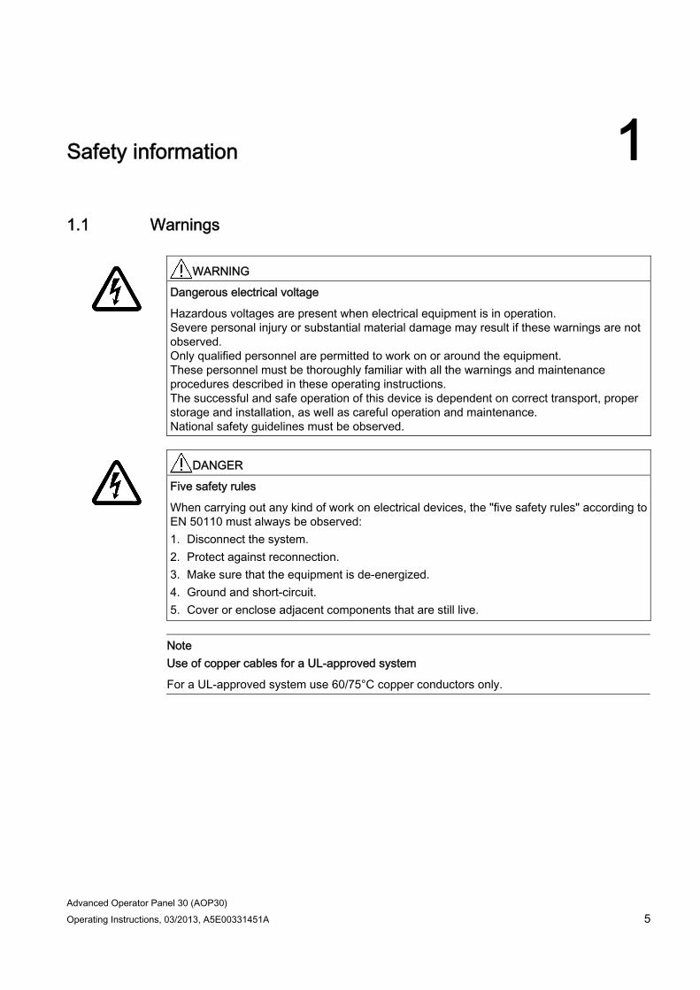
Safety information 11.1 Warnings
WARNING
Dangerous electrical voltage
Hazardous voltages are present when electrical equipment is in operation. Severe personal injury or substantial material damage may result if these warnings are not observed. Only qualified personnel are permitted to work on or around the equipment. These personnel must be thoroughly familiar with all the warnings and maintenance procedures described in these operating instructions. The successful and safe operation of this device is dependent on correct transport, proper storage and installation, as well as careful operation and maintenance. National safety guidelines must be observed.
DANGER
Five safety rules
When carrying out any kind of work on electrical devices, the "five safety rules" according to EN 50110 must always be observed: 1. Disconnect the system. 2. Protect against reconnection. 3. Make sure that the equipment is de-energized. 4. Ground and short-circuit. 5. Cover or enclose adjacent components that are still live.
Note Use of copper cables for a UL-approved system
For a UL-approved system use 60/75°C copper conductors only.
Safety information 1.2 Safety and application instructions
Advanced Operator Panel 30 (AOP30) 6 Operating Instructions, 03/2013, A5E00331451A
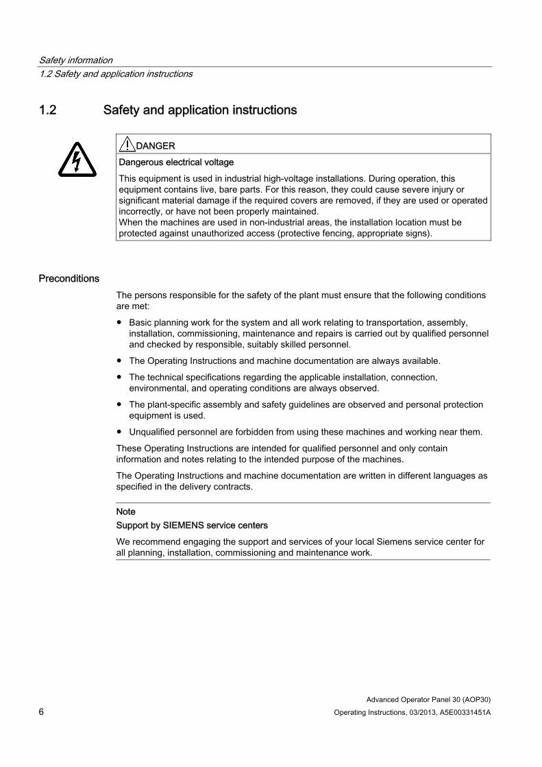
1.2 Safety and application instructions
DANGER
Dangerous electrical voltage
This equipment is used in industrial high-voltage installations. During operation, this equipment contains live, bare parts. For this reason, they could cause severe injury or significant material damage if the required covers are removed, if they are used or operated incorrectly, or have not been properly maintained. When the machines are used in non-industrial areas, the installation location must be protected against unauthorized access (protective fencing, appropriate signs).
Preconditions The persons responsible for the safety of the plant must ensure that the following conditions are met:
● Basic planning work for the system and all work relating to transportation, assembly, installation, commissioning, maintenance and repairs is carried out by qualified personnel and checked by responsible, suitably skilled personnel.
● The Operating Instructions and machine documentation are always available.
● The technical specifications regarding the applicable installation, connection, environmental, and operating conditions are always observed.
● The plant-specific assembly and safety guidelines are observed and personal protection equipment is used.
● Unqualified personnel are forbidden from using these machines and working near them.
These Operating Instructions are intended for qualified personnel and only contain information and notes relating to the intended purpose of the machines.
The Operating Instructions and machine documentation are written in different languages as specified in the delivery contracts.
Note Support by SIEMENS service centers
We recommend engaging the support and services of your local Siemens service center for all planning, installation, commissioning and maintenance work.
Safety information 1.3 Components that can be destroyed by electrostatic discharge (ESD)
Advanced Operator Panel 30 (AOP30) Operating Instructions, 03/2013, A5E00331451A 7
1.3 Components that can be destroyed by electrostatic discharge (ESD)
CAUTION Components sensitive to electrostatic charge
The board contains components that can be destroyed by electrostatic discharge. These components can be easily destroyed if not handled properly. If you do have to use electronic boards, however, please observe the following: You should only touch electronic boards if absolutely necessary. When you touch boards, however, your body must be electrically discharged
beforehand. Boards must not come into contact with highly insulating materials (such as plastic
parts, insulated desktops, articles of clothing manufactured from man-made fibers). Boards must only be placed on conductive surfaces. Boards and components should only be stored and transported in conductive packaging
(such as metalized plastic boxes or metal containers). If the packaging material is not conductive, the boards must be wrapped with a
conductive packaging material (such as conductive foam rubber or household aluminum foil).
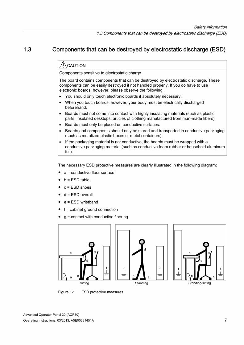
The necessary ESD protective measures are clearly illustrated in the following diagram:
● a = conductive floor surface
● b = ESD table
● c = ESD shoes
● d = ESD overall
● e = ESD wristband
● f = cabinet ground connection
● g = contact with conductive flooring
g g a
b
e
d
c
d
a c
d b
c a
e
f f f f f
Figure 1-1 ESD protective measures

Safety information 1.3 Components that can be destroyed by electrostatic discharge (ESD)
Advanced Operator Panel 30 (AOP30) 8 Operating Instructions, 03/2013, A5E00331451A

Advanced Operator Panel 30 (AOP30) Operating Instructions, 03/2013, A5E00331451A 9
General 2
Description The user-friendly AOP30 operator panel is an optional input/output device for SINAMICS G130 converters. The operator panel can be used for commissioning, operation, and diagnostic purposes.
The AOP30 communicates with the SINAMICS drive via a serial interface (RS232) using the PPI protocol. The interface is a point-to-point connection. During communication, the AOP30 is the master and the connected drive is the slave.
Structure The AOP30 is an operator panel with a graphical display and a touch-sensitive keypad. An RS232 interface is used as the interface to the drive unit. The device can be installed in a cabinet door (thickness: between 2 mm and 4 mm).
Features ● Display with green backlighting (resolution: 240 x 64 pixels)
● 26-key touch-sensitive keypad
● Connection for a 24 V DC power supply
● RS232 interface
● Time and date memory powered by internal battery backup
● 4 LEDs indicate the operating status of the drive unit:
– RUN: green
– ALARM: yellow
– FAULT: red
– LOCAL/REMOTE: green

General
Advanced Operator Panel 30 (AOP30) 10 Operating Instructions, 03/2013, A5E00331451A

Advanced Operator Panel 30 (AOP30) Operating Instructions, 03/2013, A5E00331451A 11
Mechanical installation 3
The following diagrams and descriptions explain the conditions and procedures involved in the mechanical installation of the AOP30 operator panel.
Figure 3-1 Dimension drawing of the AOP30 operator panel
Installing the operator panel (cabinet door thickness: 2 mm) 1. Cut out a 141.5 mm x 197.5 mm section in the cabinet door.
2. Fit the AOP30 operator panel in this cutout section from the outside.
3. Apply pressure to the four corners until the snap-in lugs lock into position.
Mechanical installation
Advanced Operator Panel 30 (AOP30) 12 Operating Instructions, 03/2013, A5E00331451A
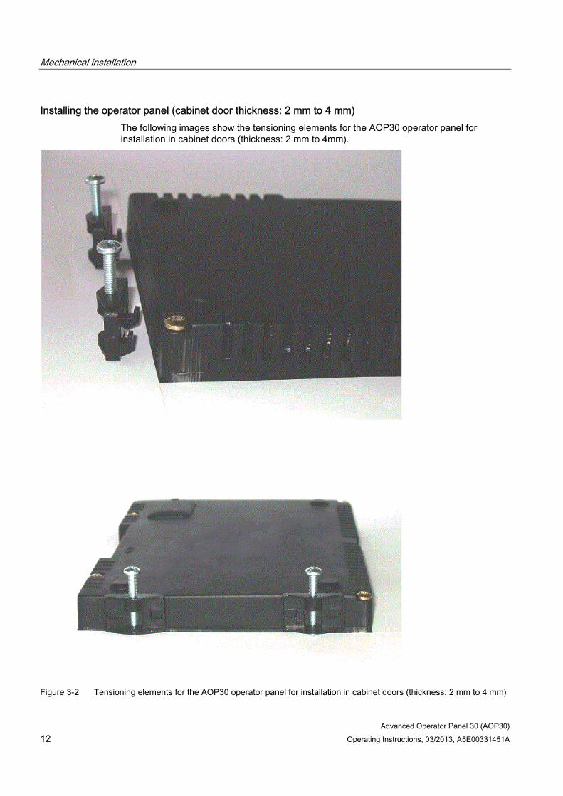
Installing the operator panel (cabinet door thickness: 2 mm to 4 mm) The following images show the tensioning elements for the AOP30 operator panel for installation in cabinet doors (thickness: 2 mm to 4mm).
Figure 3-2 Tensioning elements for the AOP30 operator panel for installation in cabinet doors (thickness: 2 mm to 4 mm)
Mechanical installation
Advanced Operator Panel 30 (AOP30) Operating Instructions, 03/2013, A5E00331451A 13
1. Cut out a 141.5 mm x 197.5 mm section in the cabinet door.
2. Fit the AOP30 operator panel in this cutout section from the outside.
3. Hook the tensioning elements into the openings provided.
4. Tighten the screws by hand to secure the tensioning elements.
NOTICE Tightening torques
Make sure that the screws for the tensioning elements are not too tight! Otherwise the operator panel housing may be damaged!

Mechanical installation
Advanced Operator Panel 30 (AOP30) 14 Operating Instructions, 03/2013, A5E00331451A

Advanced Operator Panel 30 (AOP30) Operating Instructions, 03/2013, A5E00331451A 15
Connection 4
Interfaces
Figure 4-1 AOP30 interfaces

Connection
Advanced Operator Panel 30 (AOP30) 16 Operating Instructions, 03/2013, A5E00331451A
X524: Power supply
Table 4- 1 Power supply terminals
Terminal Designation Technical data + P24 24 V DC power supply M M Ground
Max. connectable cross-section: 2.5 mm²
Note Connectable voltage supply
Only a protective extra-low voltage of Class DVC A, (PELV) acc. to EN 61800-5-1 must be connected to the power supply.
X540: serial interface (RS232)
Table 4- 2 Serial interface (RS232) X540
Pin Designation Technical data 2 RxD Receive data 3 TxD Transmit data 5 Ground Ground reference
Connector type: 9-pin SUB D socket
Note Maximum cable lengths
The maximum cable length is 10 m.
To ensure noise-free communication, you are advised to use a shielded cable and connect the cable shield to both connector housings.
NOTICE Do not connect power supply with incorrect polarity
In the operator panel electronic circuitry, a connected cable shield may possibly be connected to the signal and P24 ground. If the power supply is connected with incorrect polarity, the P24 supply via the shield and signal ground will short-circuit.
Connection
Advanced Operator Panel 30 (AOP30) Operating Instructions, 03/2013, A5E00331451A 17
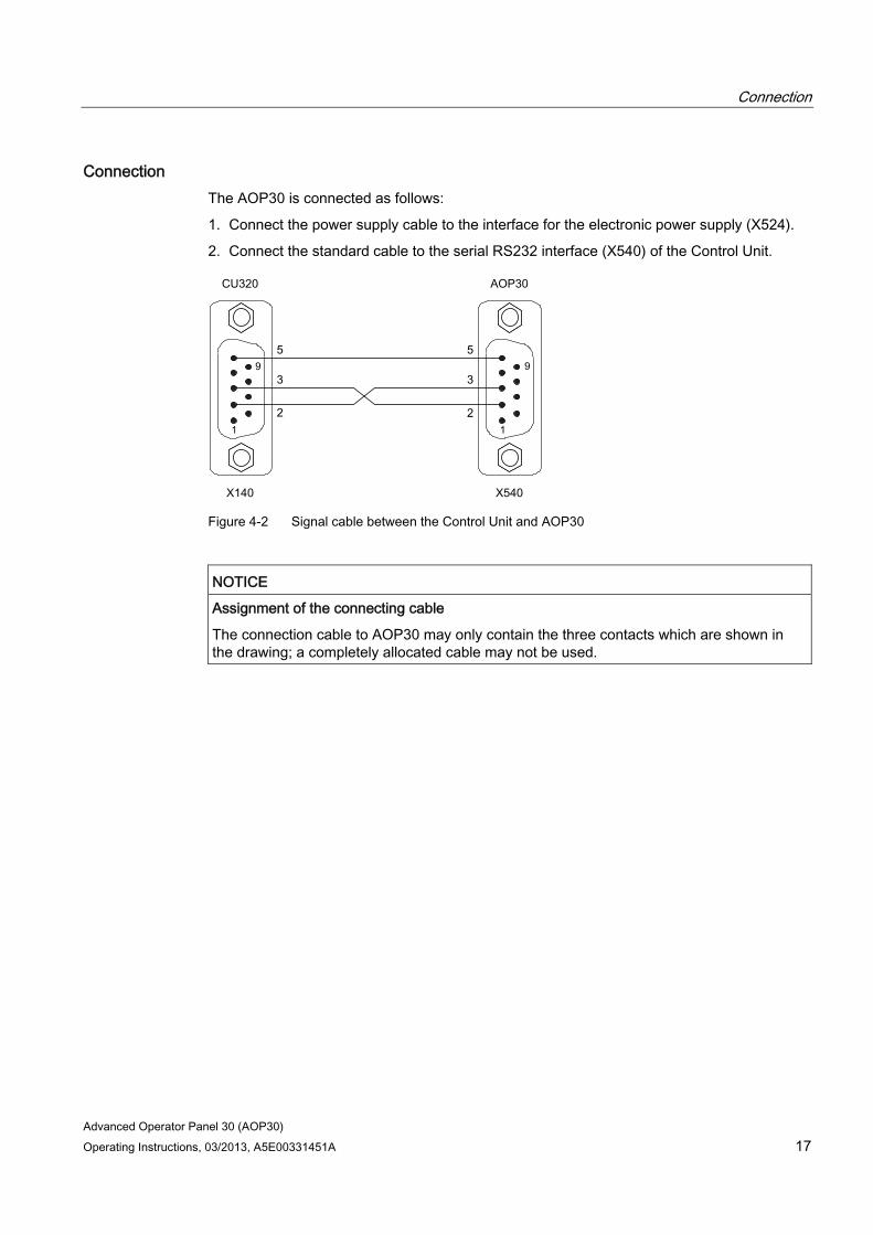
Connection The AOP30 is connected as follows:
1. Connect the power supply cable to the interface for the electronic power supply (X524).
2. Connect the standard cable to the serial RS232 interface (X540) of the Control Unit.
Figure 4-2 Signal cable between the Control Unit and AOP30
NOTICE Assignment of the connecting cable
The connection cable to AOP30 may only contain the three contacts which are shown in the drawing; a completely allocated cable may not be used.

Connection
Advanced Operator Panel 30 (AOP30) 18 Operating Instructions, 03/2013, A5E00331451A

Advanced Operator Panel 30 (AOP30) Operating Instructions, 03/2013, A5E00331451A 19
Control via the operator panel 55.1 Operator panel (AOP30) overview and menu structure
Description The operator panel can be used for the following activities:
● Parameterization (commissioning)
● Monitoring status variables
● Controlling the drive
● Diagnosing faults and alarms
All the functions can be accessed via a menu.
Your starting point is the main menu, which you can always call up using the yellow MENU key:
� �
Dialog screen for the main menu: It can be accessed at any time with the "MENU" key. Press "F2" or "F3" to navigate through the menu options in the main menu.
Note AOP reset
If the AOP no longer reacts, you can trigger an AOP reset by simultaneously pressing the key and OFF buttons (longer than two seconds) and then releasing the OFF button.

Control via the operator panel 5.1 Operator panel (AOP30) overview and menu structure
Advanced Operator Panel 30 (AOP30) 20 Operating Instructions, 03/2013, A5E00331451A
Menu structure of the operator panel
Figure 5-1 Menu structure of the operator panel
Control via the operator panel 5.2 Menu: Operation screen
Advanced Operator Panel 30 (AOP30) Operating Instructions, 03/2013, A5E00331451A 21
5.2 Menu: Operation screen
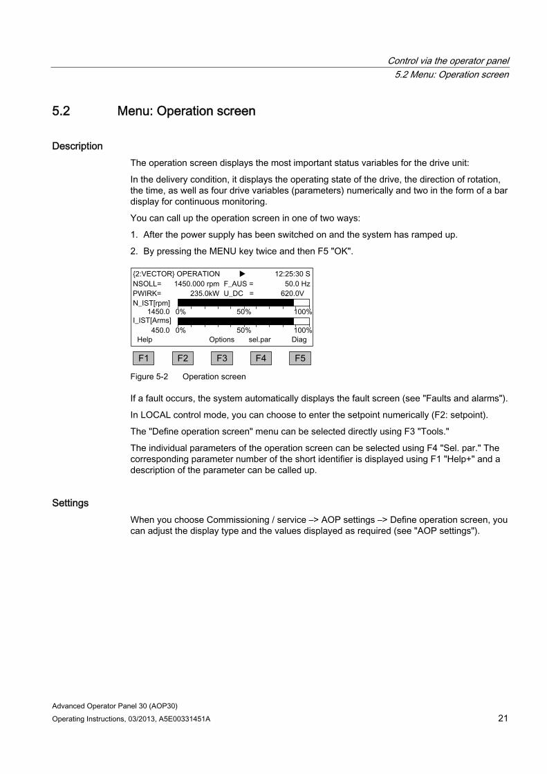
Description The operation screen displays the most important status variables for the drive unit:
In the delivery condition, it displays the operating state of the drive, the direction of rotation, the time, as well as four drive variables (parameters) numerically and two in the form of a bar display for continuous monitoring.
You can call up the operation screen in one of two ways:
1. After the power supply has been switched on and the system has ramped up.
2. By pressing the MENU key twice and then F5 "OK".
�
Figure 5-2 Operation screen
If a fault occurs, the system automatically displays the fault screen (see "Faults and alarms").
In LOCAL control mode, you can choose to enter the setpoint numerically (F2: setpoint).
The "Define operation screen" menu can be selected directly using F3 "Tools."
The individual parameters of the operation screen can be selected using F4 "Sel. par." The corresponding parameter number of the short identifier is displayed using F1 "Help+" and a description of the parameter can be called up.
Settings When you choose Commissioning / service –> AOP settings –> Define operation screen, you can adjust the display type and the values displayed as required (see "AOP settings").

Control via the operator panel 5.3 Menu: Parameterization
Advanced Operator Panel 30 (AOP30) 22 Operating Instructions, 03/2013, A5E00331451A
5.3 Menu: Parameterization You can adjust the device settings in the Parameterization menu.
The drive software is modular. The individual modules are called DOs ("drive objects").
The following DOs are available in the SINAMICS G130:
CU: General parameters for the Control Unit
VECTOR: Drive control
TM31: The TM31 terminal module (optional)
TM150: the TM150 temperature sensor module (optional)
Parameters with identical functions may exist with the same parameter number in more than one DO (e.g. p0002).
The AOP30 is used for operating devices that comprise more than one drive so that attention is focused on one drive (i.e. the "current" drive). You can switch between the drives either in the operation screen or in the main menu. The corresponding function key is labeled "Drive."
This drive determines the following:
● Operation screen
● Fault and alarm displays
● The controller (ON, OFF, …) of a drive
Depending on your requirements, you can choose between two AOP display types:
1. All parameters All the parameters present in the device are listed here. The DO to which the parameter currently selected belongs (inverted) is displayed in curly brackets in the top left of the screen.
2. DO selection In this display, you can pre-select a DO Only the parameters for this DO are then listed. (The expert list display in STARTER only uses this DO view)
In both cases, the set access level governs which parameters are displayed. You can set the access level in the menu for inhibit functions, which can be called up using the key button.
The parameters for access levels 1 and 2 are sufficient for simple applications.
At access level 3 "Expert," you can change the structure of the function by interconnecting BICO parameters.
In the data set selection menu, you can choose which of the data sets chosen is currently DISPLAYED. Data set parameters are indicated by a "c", "d", "m", "e", or "p" between the parameter number and parameter designator.
When a data set parameter is changed, the data set selection dialog appears.

Control via the operator panel 5.3 Menu: Parameterization
Advanced Operator Panel 30 (AOP30) Operating Instructions, 03/2013, A5E00331451A 23
� �
Figure 5-3 Data set selection
Explanation of the operator control dialog
● "Max" shows the maximum number of data sets parameterized (and thereby available for selection) in the drive.
● "Drive" indicates which data set is currently active in the drive.
● "AOP" indicates which particular data set is currently being displayed in the operator panel.

Control via the operator panel 5.4 Menu: Fault/alarm memory
Advanced Operator Panel 30 (AOP30) 24 Operating Instructions, 03/2013, A5E00331451A
5.4 Menu: Fault/alarm memory When you select the menu, a screen appears containing an overview of faults and alarms that are present.
For each drive object, the system indicates whether any faults or alarms are present. ("Fault" or "Alarm" appears next to the relevant drive object).
In the graphic below, you can see that at least one active fault/alarm is present for the "VECTOR" drive object. No faults/alarms are indicated for the other drive objects.
� �
Fault/alarm memory When you navigate to the line with active alarms/faults and then press the F5 <Diag> key, the system displays a screen in which you have to select the current or old alarms/faults.
� �
Display diagnostics When you navigate to the required line and then press the F5 <OK> key, the corresponding faults/alarms are displayed. The list of current faults is selected here as an example.
� �
Display of current faults A maximum of eight current faults are displayed along with their fault number and name of the fault. To display additional help regarding the cause of the problem and how to solve it, choose F1 <Help>. To acknowledge the faults, choose F5 <Ack.>. If a fault cannot be acknowledged, the fault remains.
Control via the operator panel 5.5 Menu commissioning / service
Advanced Operator Panel 30 (AOP30) Operating Instructions, 03/2013, A5E00331451A 25
5.5 Menu commissioning / service
5.5.1 Drive commissioning This option enables you to re-commission the drive from the main menu.
Basic Commissioning Only the basic commissioning parameters are queried and stored permanently.
Complete commissioning Complete commissioning with motor and encoder data entry is carried out. Following this, key motor parameters are recalculated from the motor data. The parameter values calculated during previous commissioning are lost.
In a subsequent motor identification procedure, the calculated values are overwritten.
Motor identification The selection screen for motor identification appears.
Reset fan operating time The actual operating hours of the fan in the power unit is displayed.
After a fan replacement, the operating hours counter for monitoring the fan operating time must be reset.
5.5.2 Device commissioning
Device commissioning In this menu, you can enter the device commissioning status directly. This is the only way that you can reset parameters to the factory setting for example.

Control via the operator panel 5.5 Menu commissioning / service
Advanced Operator Panel 30 (AOP30) 26 Operating Instructions, 03/2013, A5E00331451A
5.5.3 Drive diagnostics
Curve recorder The curve recorder provides a slow trace function, which can be used to monitor a signal trend. A signal selected by parameter is displayed in the form of a curve.
Figure 5-4 Curve recorder
The parameters to be displayed are selected and the graphic interpolation set with the F5 key or via the menu Commissioning/Service - AOP settings - Curve recorder settings.
In addition to the curve, the selected value is output on the display and updated every 500 ms.
Assignment of the function keys F1 to F5 is not normally displayed visibly so that the space can be fully utilized to display the curve. Pressing a function key shows the key assignments. If no further key is pressed within 5 seconds, the labeling will disappear again.
The curve can be scaled automatically or manually. This is selected with key F3 "scale+" - F4 "Auto/Manual" followed by confirmation with F5 "OK."
● Auto:
The scaling of the curve changes dynamically, it is oriented to the maximum value (for example, 12.49) and minimum value (for example, 0.00) visible in the display at the actual point in time. With buttons F2 and F3, the scaling can be changed in steps. If measured value noise is shown with an excessively high resolution as a result of the automatic scaling, then the resolution can be reduced in four steps by pressing button F2. As a result, the automatic scaling is deactivated. However, if the measured value leaves the display area, then this is extended. Automatic scaling can be reselected by pressing button F3.

Control via the operator panel 5.5 Menu commissioning / service
Advanced Operator Panel 30 (AOP30) Operating Instructions, 03/2013, A5E00331451A 27
● Manual:
After selecting manual scaling and confirmation with "OK," a window opens in which the maximum and minimum limits for scaling can be set.
� �
Figure 5-5 Curve recorder - manual scaling
After setting and applying the limits, you switch to the curve recorder and manual scaling is used.
If the current measured values are outside the displayable range, the range will automatically be extended.
Note Changing the parameter for the curve recorder in manual scaling
When the parameter for the curve recorder is changed the following occurs with manual scaling: If the current parameter has lower values than the currently set scaling, the scaling will
be retained. If the current parameter has higher values than the currently set scaling, the scaling
will be adjusted automatically.
Help on the curve recorder can be opened with key F1.
The curve recorder is exited by pressing the MENU button.
Note No recording of data
The values displayed in the recorder are not recorded and saved, they are only used for display until the screen form is exited.

Control via the operator panel 5.5 Menu commissioning / service
Advanced Operator Panel 30 (AOP30) 28 Operating Instructions, 03/2013, A5E00331451A
5.5.4 AOP settings
Control settings This defines the settings for the control keys in LOCAL mode (see "Operation / Control via the operator panel / Operation via the operator panel").
Display settings In this menu, you set the lighting, brightness, and contrast for the display.
Defining the operation screen In this menu, you can switch between five operation screens. You can set the parameters that are to be displayed.
� �
� �
� �
� �
� �
Figure 5-6 Defining the operation screen

Control via the operator panel 5.5 Menu commissioning / service
Advanced Operator Panel 30 (AOP30) Operating Instructions, 03/2013, A5E00331451A 29
The following image shows how the entries are assigned to the screen positions:
��
�
��
Figure 5-7 Layout of the entries in the operation screen
Lists of signals for the operating screen form The following tables list some of the main signals for the operation screen along with the associated reference variables and default settings for fast commissioning.

Control via the operator panel 5.5 Menu commissioning / service
Advanced Operator Panel 30 (AOP30) 30 Operating Instructions, 03/2013, A5E00331451A
VECTOR object
Table 5- 1 List of signals for the operation screen - VECTOR object
Signal Parameters Short name Unit Scaling (100 %=...) See table below
Factory setting (entry no.) Speed setpoint upstream of ramp-function generator
(1) r1114 NSETP 1/min p2000
Output frequency (2) r0024 F_OUT Hz Reference frequency Power smoothed (3) r0032 PACTV kW r2004 DC link voltage smoothed (4) r0026 U_DC V p2001 Actual speed value smoothed (5) r0021 N_ACT 1/min p2000 Absolute actual current smoothed (6) r0027 I_IST A p2002 Motor temperature (7) r0035 1) T_MOT °C Reference temperature Converter temperature (8) r0037 T_LT °C Reference temperature Actual torque smoothed (9) r0031 M_ACT Nm p2003 Converter output voltage smoothed (10) r0025 C_OUT V p2001 For diagnostic purposes Speed setpoint smoothed r0020 NSETP 1/min p2000 Control factor smoothed r0028 AUSST % Reference modulation
depth Field-producing current component r0029 IDACT A p2002 Torque-producing current component r0030 IQACT A p2002 Converter overload Degree of thermal overload
r0036 LTI2T % 100 % = Shutdown
Speed actual value motor encoder r0061 N_ACT 1/min p2000 Speed setpoint after filter r0062 NSETP 1/min p2000 Actual speed smoothed r0063 N_ACT 1/min p2000 Control deviation r0064 NDIFF 1/min p2000 Slip frequency r0065 FSCHL Hz Reference frequency Output frequency r0066 F_OUT Hz Reference frequency Output voltage r0072 UACT V p2001 Control factor r0074 AUSST % Reference modulation
depth Torque-generating actual current r0078 IQACT A p2002 Actual torque value r0080 M_ACT Nm p2003 For further diagnostic purposes Fixed speed setpoint effective r1024 1/min p2000 Active motorized potentiometer setpoint r1050 1/min p2000 Resulting speed setpoint r1119 NSETP 1/min p2000 Speed controller output r1508 NREGY Nm p2003 I component of speed controller r1482 NREGI Nm p2003 PROFIBUS setpoint r2050 PBSOL 1/min p2000
1) If a temperature sensor has not been installed, a value of –200 °C is displayed.

Control via the operator panel 5.5 Menu commissioning / service
Advanced Operator Panel 30 (AOP30) Operating Instructions, 03/2013, A5E00331451A 31
Normalization for VECTOR object
Table 5- 2 Normalization for VECTOR object
Size Scaling parameter Default for quick commissioning Reference speed 100% = p2000 p2000 = Maximum speed (p1082) Reference voltage 100% = p2001 p2001 = 1000 V Reference current 100% = p2002 p2002 = Current limit (p0640) Reference torque 100% = p2003 p2003 = 2 x rated motor torque Reference power 100% = r2004 r2004 = (p2003 x p2000 x π) / 30 Reference frequency 100% = p2000/60 Reference modulation depth
100 % = Maximum output voltage without overload
Reference flux 100 % = Rated motor flux Reference temperature 100% = p2006 p2006 = 100°C
TM31 object
Table 5- 3 List of signals for the operation screen – TM31 object
Signal Parameter Short name Unit Scaling (100 % = ...)
Analog input 0 [V, mA] r4052[0] AI_UI V, mA V: 100 V / mA: 100 mA Analog input 1 [V, mA] r4052[1] AI_UI V, mA V: 100 V / mA: 100 mA Analog input 0, scaled r4055[0] AI_% % as set in p200x Analog input 1, scaled r4055[1] AI_% % as set in p200x
Setting the date/time (for date stamping of error messages) In this menu, you set the date and time.
You can also set whether and/or how the AOP and drive unit are to be synchronized. Synchronization of the AOP with the drive enables error messages to be date- and time-stamped.
Note Display format for the time
The drive unit displays the time in parameter r3102 in the UTC format (days/milliseconds since 1970-01-01).
Under "Additional settings," settings for synchronization can be made:

Control via the operator panel 5.5 Menu commissioning / service
Advanced Operator Panel 30 (AOP30) 32 Operating Instructions, 03/2013, A5E00331451A
Synchronization
● None (factory setting) The times for the AOP and drive unit are not synchronized.
● AOP -> Drive
– If you activate this option, the AOP and drive unit are synchronized immediately whereby the current AOP time is transferred to the drive unit.
– The current AOP time is transferred to the drive unit every time the AOP is started.
– Depending on the set synchronization interval, the current AOP time is transferred to the drive unit.
Note Flashing "S"
If the AOP detects a difference between RAM and ROM during synchronization to the drive unit, this is indicated by a flashing "S" at the top right in the display or, if operator input and/or parameter assignment has been disabled, by a flashing key symbol.
● Drive -> AOP
– If you activate this option, the AOP and drive unit are synchronized immediately whereby the current drive unit time is transferred to the AOP.
– The current drive unit time is transferred to the AOP every time the AOP is started.
– Depending on the set synchronization interval, the current drive unit time is transferred to the AOP.
Synchronization interval
The interval for time synchronization is set from 1 hour (factory setting) to 99 hours.
For the interval, the time in the AOP from the time of the last change of the interval is decisive.
Daylight saving time changeover
● No (factory setting) The time does automatically change over to daylight-saving time.
● Yes Selection is only possible if synchronization is set to "None" or "AOP -> Drive." The time automatically changes over between daylight-saving and standard time. After changeover, synchronization is performed immediately on "AOP -> Drive" synchronization, irrespective of the set synchronization interval.
Changes to the synchronization must be saved with "Save".
Control via the operator panel 5.5 Menu commissioning / service
Advanced Operator Panel 30 (AOP30) Operating Instructions, 03/2013, A5E00331451A 33
Date format In this menu, the date format can be set:
● DD.MM.YYYY: European date format
● MM/DD/YYYY: North American data format
DO name display mode In this menu, you can switch the display of the DO name between the standard abbreviation (e.g. VECTOR) and a user-defined DO name (e.g. Motor_1).
User-defined DO name (factory setting: NO)
● Yes: The "User-defined DO name" stored in parameter p0199 is displayed, instead of the standard DO abbreviation.
● No: The standard DO abbreviation is displayed.
Normalization to motor current In this menu, the reference variable for the bar-type display of parameter r0027 (absolute current actual value smoothed) can be changed over in the operating screen forms.
Normalization to motor current (factory setting: NO)
● Yes: The bar-type display of parameter r0027 in the operating screen form is displayed based on parameter p0305 (rated motor current).
● No: The bar-type display of parameter r0027in the operating screen form is displayed based on parameter p2002 (reference current).
Reset AOP settings When you choose this menu option, the AOP factory settings for the following are restored:
● Language
● Display (brightness, contrast)
● Operation screen
● Control settings
Note Restoring the factory setting
When you reset parameters, all settings that are different to the factory settings are reset immediately. This may cause the cabinet unit to switch to a different, unwanted operational status.
For this reason, you should always take great care when resetting parameters.

Control via the operator panel 5.5 Menu commissioning / service
Advanced Operator Panel 30 (AOP30) 34 Operating Instructions, 03/2013, A5E00331451A
Curve recorder settings In this menu, you can select the parameter whose signal is to be displayed in the form of a trend curve in the curve recorder.
In addition, the setting of the interpolation can be selected to better display quantities that suddenly change (as a step function).
Interpolation (factory setting: NO)
● NO: Only the measured values are displayed as points, without a connecting line between points.
● 1: The measured values are connected by a vertical line.
● 2: The measured values are connected by a line offset at the center.
5.5.5 AOP diagnostics
Software/database version You can use this menu to display the firmware and database versions.
The database version must be compatible with the drive software status (you can check this in parameter r0018).
Battery status In this menu, you can display the battery voltage numerically (in Volts) or as a bar display. The battery ensures that the data in the database and the current time are retained.
When the battery voltage is represented as a percentage, a battery voltage of ≤ 2 V is equal to 0%, and a voltage of ≥ 3 V to 100%.
The data is secure up to a battery voltage of 2 V.
● If the battery voltage is ≤ 2.45 V, the message "Replace battery" is displayed in the status bar.
● If the battery voltage is ≤ 2.30 V, the system displays the following message: "Warning: weak battery".
● If the battery voltage is ≤ 2 V, the system displays the following message: "Caution: The battery is dead".
● If the time and/or database are not available after the system has been switched off for a prolonged period due to the voltage being too low, the loss is established by means of a CRC check when the system is switched on again. This triggers a message instructing the user to replace the battery and then load the database and/or set the time.
For instructions on how to change the battery, see "Maintenance and servicing."
Control via the operator panel 5.6 Sprachauswahl/Language selection
Advanced Operator Panel 30 (AOP30) Operating Instructions, 03/2013, A5E00331451A 35
Keyboard test In this screen, you can check that the keys are functioning properly. Keys that you press are represented on a symbolic keyboard on the display. You can press the keys in any order you wish. You cannot exit the screen (F4 – "back") until you have pressed each key at least once.
Note Exit keyboard test
Alternatively, you can exit the keyboard test screen by pressing any key and holding it down.
LED test In this screen, you can check that the 4 LEDs are functioning properly.
5.6 Sprachauswahl/Language selection The operator panel downloads the texts for the different languages from the drive.
You can change the language of the operator panel via the "Sprachauswahl/Language selection" menu.
Note Additional languages for the display
Languages in addition to the current available languages in the display are available on request.
5.7 Operation via the operator panel (LOCAL mode) You activate the control keys by switching to LOCAL mode. If the green LED in the LOCAL/REMOTE key does not light up, the key is not active.
Note OFF in REMOTE
If the "OFF in REMOTE" function is activated, the LED in the LOCAL-REMOTE key flashes.
For LOCAL master control, all of the supplementary setpoints are deactivated.
Control via the operator panel 5.7 Operation via the operator panel (LOCAL mode)
Advanced Operator Panel 30 (AOP30) 36 Operating Instructions, 03/2013, A5E00331451A
After the master control has been transferred to the operator panel, the BICO interconnections at bit 0 to bit 10 of the control word of the sequence control are not effective (refer to function diagram 2501).
Note Message "Other device has master control"
If STARTER has master control, then when pressing the LOCAL-REMOTE button, the "Other device has master control" message is displayed, and the master control transfer is rejected.
5.7.1 LOCAL/REMOTE key Activating the LOCAL mode: Press the LOCAL key.
LOCAL mode: LED lights up
REMOTE mode: LED does not light up: the ON, OFF, JOG, direction reversal, faster, and slower keys are not active.
Settings: MENU – Commissioning/Service – AOP Settings – Control Settings Save LOCAL mode (factory setting: yes)
● Yes: The "LOCAL" or "REMOTE" operating mode is saved when the power supply is switched off and restored when the power supply is switched back on.
● No: "LOCAL" or "REMOTE" operating mode is not saved. "REMOTE" is active when the supply voltage is switched back on.
OFF in REMOTE (factory setting: No)
● Yes: The OFF key functions in REMOTE mode even if the drive is being controlled by external sources (fieldbus, customer terminal strip, NAMUR terminal strip). WARNING: This function is not an EMERGENCY STOP function!
● No: The OFF key only functions in LOCAL mode.
LOCAL/REMOTE also during operation (factory setting: No)
● Yes: You can switch between LOCAL and REMOTE when the drive is switched on (motor is running).
● No: Before the system switches to LOCAL, a check is carried out to determine whether the drive is in the operational status. If so, the system does not switch to local and outputs the error message "Local mode during operation not possible". Before the system switches to REMOTE, the drive is switched off and the setpoint is set to 0.

Control via the operator panel 5.7 Operation via the operator panel (LOCAL mode)
Advanced Operator Panel 30 (AOP30) Operating Instructions, 03/2013, A5E00331451A 37
5.7.2 ON key / OFF key ON key: always active in LOCAL when the operator input inhibit is deactivated.
OFF key: in the factory setting, acts as OFF1 = ramp-down at the deceleration ramp (p1121); when n = 0: voltage disconnection (only if a main contactor is installed) The OFF key is effective in the LOCAL mode and when the "OFF in REMOTE" function is active.
Settings: Menu – Commissioning / Service – AOP Settings – Control Settings Red OFF key acts as: (factory setting: OFF1)
● OFF1: Ramp-down on the deceleration ramp (p1121)
● OFF2: Immediate pulse block, motor coasts to a standstill
● OFF3: Ramp-down on the emergency stop ramp (p1135)
5.7.3 Switching between clockwise and counter-clockwise rotation
Settings: MENU – Commissioning/Service – AOP Settings – Control Settings Switching between CCW/CW (factory setting: no)
● Yes: Switching between CW/CCW rotation by means of the CW/CCW key possible in LOCAL mode
● No: The CW/CCW key has no effect in LOCAL mode
For safety reasons, the CW/CCW key is disabled in the factory setting (pumps and fans must normally only be operated in one direction).
In the operation status in LOCAL mode, the current direction of rotation is indicated by an arrow next to the operating mode.
Note Activation of CCW/CW changeover
You have to make additional settings when switching between CW/CCW rotation.
Control via the operator panel 5.7 Operation via the operator panel (LOCAL mode)
Advanced Operator Panel 30 (AOP30) 38 Operating Instructions, 03/2013, A5E00331451A
5.7.4 Jog
Settings: MENU – Commissioning/Service – AOP settings – Control settings JOG key active (factory setting: No)
● Yes: The jog key is effective in the LOCAL mode in the state "ready to power-up" (not in "operation"). The speed that is set in parameter p1058 is approached.
● No: The JOG key has no effect in the LOCAL mode
5.7.5 Increase setpoint / decrease setpoint You can use the Increase and Decrease keys to enter the setpoint with a resolution of 1% of the maximum speed.
You can also enter the setpoint numerically. To do so, press F2 in the operation screen. The system displays an field for entering the required speed. Enter the required value using the numeric keypad. Press F5 "OK" to confirm the setpoint.
When you enter values numerically, you can enter any speed between the minimum speed (p1080) and the maximum speed (p1082).
Setpoint entry in LOCAL mode is unipolar. You can change the direction of rotation by pressing the key that allows you to switch between CW/CCW rotation.
● CW rotation and "Increase key" mean: The displayed setpoint is positive and the output frequency is increased.
● CCW rotation and "Increase key" mean: The displayed setpoint is negative and the output frequency is increased.
Control via the operator panel 5.7 Operation via the operator panel (LOCAL mode)
Advanced Operator Panel 30 (AOP30) Operating Instructions, 03/2013, A5E00331451A 39
5.7.6 AOP setpoint
Settings: MENU – Commissioning/Service – AOP Settings – Control Settings Save AOP setpoint (factory setting: no)
● Yes: In LOCAL mode, the last setpoint (once you have released the INCREASE or DECREASE key or confirmed a numeric entry) is saved. The next time you switch the system on in LOCAL mode, the saved value is selected. This is also the case if you switched to REMOTE in the meantime or the power supply was switched off. When the system is switched from REMOTE to LOCAL mode while the drive is switched on (motor is running), the actual value that was last present is set as the output value for the motorized potentiometer setpoint and saved. If the system is switched from REMOTE to LOCAL mode while the drive is switched off, the motorized potentiometer setpoint that was last saved is used.
● No: On power-up in LOCAL mode, the speed is always set to the value entered under "AOP starting setpoint". When the system is switched from REMOTE to LOCAL mode while the drive is switched on (motor is running), the actual value that was last present is set as the output value for the AOP setpoint.
AOP setpoint ramp-up time (factory setting: 10 s)
AOP setpoint ramp-down time (factory setting: 10 s)
● Recommendation: set as ramp-up/ramp-down time (p1120/p1121). Changing the ramp-up/ramp-down times does not affect the settings for parameters p1120 and p1121 because this is an AOP-specific setting.
AOP starting setpoint (factory setting: 0.000 rpm)
Note Internal ramp-function generator
The internal drive ramp-function generator is always active.
Settings: MENU – Commissioning/Service – AOP settings – Control settings Save AOP local mode (factory setting: no)
● Yes: Deactivates the "Control via operator panel" function, thereby disabling the LOCAL/REMOTE key.
● No: Activates the LOCAL/REMOTE key.
Note Lock LOCAL
LOCAL functionality can also be inhibited on the drive by means of the p0806 parameter (BI: Inhibit master control).
Control via the operator panel 5.7 Operation via the operator panel (LOCAL mode)
Advanced Operator Panel 30 (AOP30) 40 Operating Instructions, 03/2013, A5E00331451A
Settings: MENU – Commissioning/Service – AOP Settings – Control Settings Acknowledge error from the AOP (factory setting: yes)
● Yes: Errors can be acknowledged via the AOP.
● No: Errors cannot be acknowledged via the AOP.
Settings: MENU – Commissioning/Service – AOP settings – Control settings CDS changeover via AOP (factory setting: No)
● Yes: In the LOCAL mode, in the operating screen form the active CDS can the changed by one. This is helpful, if operation via an AOP would not be possible due to the fact that a standard telegram is active. When CDS0 or 2 is active, "CDS+1" switches to CDS1 or CDS3. When CDS1 or 3 is active, "CDS-1" switches to CDS0 or CDS2.
● No: In the LOCAL mode, in the operating screen form the active CDS cannot be changed by one.
5.7.7 Timeout monitoring In "LOCAL" mode or if "OFF in REMOTE" is active, the drive is shut down in an adjustable time if the data cable between the AOP and drive is disconnected (factory setting 3000 ms).
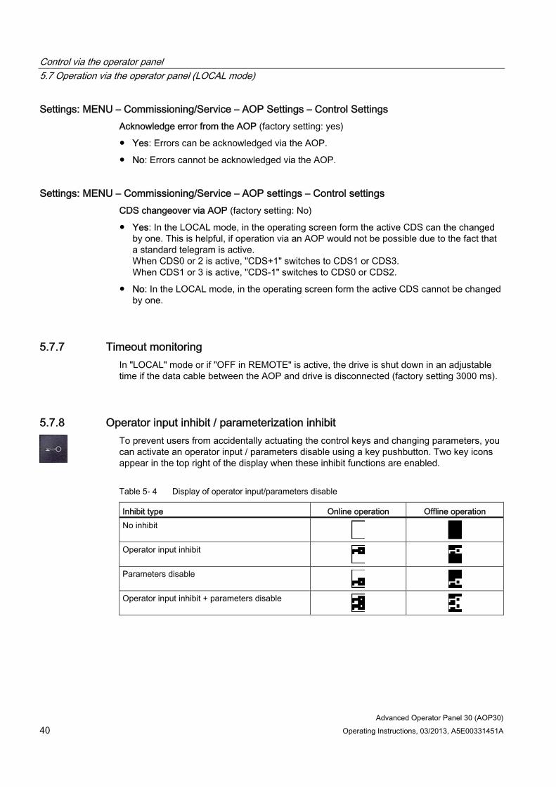
5.7.8 Operator input inhibit / parameterization inhibit To prevent users from accidentally actuating the control keys and changing parameters, you can activate an operator input / parameters disable using a key pushbutton. Two key icons appear in the top right of the display when these inhibit functions are enabled.
Table 5- 4 Display of operator input/parameters disable
Inhibit type Online operation Offline operation No inhibit
Operator input inhibit
Parameters disable
Operator input inhibit + parameters disable

Control via the operator panel 5.7 Operation via the operator panel (LOCAL mode)
Advanced Operator Panel 30 (AOP30) Operating Instructions, 03/2013, A5E00331451A 41
Settings
� � ��
� �
Figure 5-8 Set inhibit functions
The "Operator input inhibit" setting can be changed directly via <F5> "Change" once you have selected the selection field.
When "Parameterization inhibit" is activated, you have to enter a numeric password (repeat this entry). You must also enter this password when deactivating "Parameterization inhibit".
Operator input inhibit (factory setting: not active)
● Active: The parameters can still be viewed, but a parameter value cannot be saved (message: "Note: operator input inhibit active"). The OFF key (red) is enabled. The LOCAL, REMOTE, ON (green), JOG, CW/CCW, INCREASE, and DECREASE keys are disabled.
Parameterization inhibit (factory setting: not active)
● Active: Parameters cannot be changed unless a password is entered. The parameterization process is the same as with the operator input inhibit. If you try and change parameters, the message "Note: Parameterization inhibit active" is displayed. All the control keys can, however, still be actuated.
Access level (factory setting: Expert):
The different parameters required for this complex application are filtered so that they can be displayed as clearly as possible. You select them according to the access level.
An expert level, which must only be used by expert personnel, is required for certain actions.
Note Copy from RAM to ROM
When the operator input inhibit or parameterization inhibit is activated, a "Copy from RAM to ROM" is automatically executed to back the parameter settings up in non-volatile memory on the memory card.

Control via the operator panel 5.8 Faults and alarms
Advanced Operator Panel 30 (AOP30) 42 Operating Instructions, 03/2013, A5E00331451A
5.8 Faults and alarms
Indicating faults and alarms If a fault occurs, the drive displays the fault and/or alarm on the operator panel. Faults are indicated by the red "FAULT" LED and a fault screen is automatically displayed. You can use the F1 Help function to call up information about the cause of the fault and how to remedy it. You can use F5 Ack. to acknowledge a stored fault.
Alarms are indicated by means of the yellow "ALARM" LED. The system also displays a note in the status bar providing information on the cause.
What is a fault? A fault is a message from the drive indicating an error or other exceptional (unwanted) status that causes the drive to shutdown. This could be caused by a fault within the converter or an external fault triggered, for example, by the winding temperature monitor for the motor. The faults are displayed and can be reported to a higher-level control system via PROFIBUS. In the factory default setting, the message "converter fault" is also sent to a relay output. Once you have rectified the cause of the fault, you have to acknowledge the fault message.
What is an alarm? An alarm is the response to a fault condition identified by the drive. It does not result in the drive being switched off and does not have to be acknowledged. Alarms are "self acknowledging", that is, they are reset automatically when the cause of the alarm has been eliminated.
Fault and alarm displays Every fault and alarm is entered in the fault/alarm buffer along with time the error occurred. The time stamp refers to the system time (r2114).
You can call up an overview screen that displays the current status of faults and/or alarms for every drive object in the system by choosing MENU – Fault memory / alarm memory.
A context menu featuring the "Back" and "Quit" options appears when you press F4 "Next". The function required can be selected using F2 and F3 and executed by pressing F5 "OK". The "Acknowledge" function sends an acknowledgement signal to each drive object. The red FAULT LED extinguishes once all the faults have been acknowledged.

Control via the operator panel 5.9 Saving the parameters permanently
Advanced Operator Panel 30 (AOP30) Operating Instructions, 03/2013, A5E00331451A 43
� � � �
Figure 5-9 Fault screen
You can use F5 Ack. to acknowledge a stored fault.
� � � �
Figure 5-10 Alarm screen
Alarms that are no longer active are removed from the alarm memory with F5 Clear.
5.9 Saving the parameters permanently
Description If parameters have been changed using the operator panel (confirm with OK in the Parameter Editor), the new values are initially stored in the volatile memory (RAM) of the converter. An "S" flashes in the top right of the AOP display until they are saved to a permanent memory. This indicates that at least 1 parameter has been changed and not yet stored permanently.
Two methods are available for permanently saving parameters that have been changed:
● To store the parameters permanently, choose <MENU> <Parameterization> <OK> <Permanent parameter transfer>.
● When confirming a parameter setting with OK, press the OK key for > 1 s. The system displays a message asking you whether the setting is to be saved in the EEPROM. If you press "Yes", the system saves the setting in the EEPROM. If you press "No", the setting is not saved permanently and the "S" starts flashing.
In both cases, all changes that have not yet been saved permanently are stored in the EEPROM.

Control via the operator panel 5.10 Parameterization errors
Advanced Operator Panel 30 (AOP30) 44 Operating Instructions, 03/2013, A5E00331451A
5.10 Parameterization errors If a fault occurs when reading or writing parameters, a popup window containing the cause of the problem is displayed.
The system displays:
Parameter write error (d)pxxxx.yy:0xnn
and a plain-text explanation of the type of parameterization error.

Advanced Operator Panel 30 (AOP30) Operating Instructions, 03/2013, A5E00331451A 45
Maintenance and servicing 66.1 Replacing the backup battery
Replacing the backup battery
Figure 6-1 Replacing the backup battery

Maintenance and servicing 6.1 Replacing the backup battery
Advanced Operator Panel 30 (AOP30) 46 Operating Instructions, 03/2013, A5E00331451A
1. Disconnect the 24 V DC power supply cable.
2. Disconnect the communication cable on the operator panel.
3. Open the cover of the battery compartment.
4. Remove the old battery.
5. Insert the new battery.
6. Carry out any other work by reversing the sequence.
Table 6- 1 Technical specifications of the backup battery
Type CR2032 3 V lithium battery Manufacturer Maxell, Sony, Panasonic Nominal capacity 220 mAh Self-discharge at 20 °C 1 %/year Service life (in backup mode) > 1 year at 70 °C; >1.5 years at 20 °C Service life (in operation) > 2 years
Note Replace battery within one minute
The battery must be replaced within one minute to ensure that no AOP settings are lost.
Note Battery disposal
The battery must be disposed of in accordance with the applicable country-specific guidelines and regulations.

Maintenance and servicing 6.2 Downloading new operator panel firmware from the PC
Advanced Operator Panel 30 (AOP30) Operating Instructions, 03/2013, A5E00331451A 47
6.2 Downloading new operator panel firmware from the PC
Description Firmware might need to be loaded to the AOP if the AOP functionality needs to be upgraded.
If, once the drive has powered up, the CompactFlash Card is found to contain a newer version of the firmware, a message will appear on the AOP30 prompting you to load the new firmware. You should click "YES" in response to this prompt. The firmware will then be loaded automatically on the operator panel and the following dialog screen will appear.
Figure 6-2 Dialog screen: loading firmware
If the firmware cannot be loaded successfully, it can be loaded using the following manual method.
The load program LOAD_AOP30 and the firmware file can be found on the CD.
Loading the firmware 1. Establish the RS232 connection from the PC to the AOP30.
2. Provide the supply voltage (24 V DC).
3. Start the LOAD_AOP30 program on the PC.
4. Choose the PC interface (COM1, COM2).
5. Choose and open the firmware (AOP30.H86).
6. Follow the instructions in the status window of the program and connect the power supply for the AOP30 while pressing the red key (O).
7. The load procedure is started automatically.
8. Switch the power on (switch the power supply off and then back on).

Maintenance and servicing 6.2 Downloading new operator panel firmware from the PC
Advanced Operator Panel 30 (AOP30) 48 Operating Instructions, 03/2013, A5E00331451A

Advanced Operator Panel 30 (AOP30) Operating Instructions, 03/2013, A5E00331451A 49
Technical specifications 7
Table 7- 1 Technical specifications
Power supply 24 V DC (20.4 V to 28.8 V) Current requirements - Without backlighting - With maximum backlighting
<100 mA <200 mA
Data interface RS232 interface, PPI protocol Back-up battery 3 V lithium CR2032 Operating temperature 0 to 55°C Storage and transport temperature -25 to +70°C Degree of protection IP20 (inside cabinet)
IP55 (outside cabinet) Certification cULus
CE Product standard EN 61800-5-1 Dimensions Information on this can be found in the "Mechanical
installation" section Weight 0.55 kg

Technical specifications
Advanced Operator Panel 30 (AOP30) 50 Operating Instructions, 03/2013, A5E00331451A

Advanced Operator Panel 30 (AOP30) Operating Instructions, 03/2013, A5E00331451A 51
Index
A Acknowledge error from the AOP, 40 AOP setpoint, 39
C CDS changeover via AOP, 40 Changing the language, 35
D Decrease Key, 38 Downloading the firmware (operator panel), 47
F Faults and alarms, 42
I Increase Key, 38
J Jog, 38 JOG, 38
L LOCAL/REMOTE key, 36 Lock AOP LOCAL Mode, 39
M Menu
AOP diagnostics, 34 AOP30 settings, 28 Basic Commissioning, 25 Battery status, 34 Commissioning / service, 25 Complete commissioning, 25 Control settings, 28
Curve recorder, 26 Curve recorder settings, 34 Database version, 34 Date format, 33 Defining the operation screen, 28 Device commissioning, 25 Display settings, 28 DO name display mode, 33 Drive commissioning, 25 Drive diagnostics, 26 Fault/alarm memory, 24 Keyboard test, 35 LED test, 35 Motor identification, 25 Normalization to motor current, 33 Operation screen, 21 Reset AOP settings, 33 Reset fan operating time, 25 Setting the date, 31 Setting the time, 31 Software Version, 34 Sprachauswahl/Language selection, 35 Structure, 20
O OFF Key, 37 ON Key, 37 Operation screen, 21 Operator input inhibit / parameters inhibit key, 40 Operator panel
Overview, 19
P Parameterization errors, 44
S Saving the Parameters, Permanently, 43 Switching between clockwise and counter-clockwise rotation, 37
T Timeout monitoring, 40

www.siemens.com/automation
Subject to change without prior notice© Siemens AG, 2004 - 2013
Siemens AGIndustry SectorDrive TechnologiesLarge DrivesP.O. Box 474390025 NUREMBERGGERMANY