Advanced Multiphysics Thermal-Hydraulics Models...
15
ADVANCED MULTIPHYSICS THERMAL-HYDRAULICS MODELS FOR THE HIGH FLUX ISOTOPE REACTOR Prashant K. Jain and James D. Freels Oak Ridge National Laboratory PO Box 2008, Oak Ridge, TN 37831 USA [email protected], [email protected] ABSTRACT Engineering design studies to determine the feasibility of converting the High Flux Isotope Reactor (HFIR) from using highly enriched uranium (HEU) to low-enriched uranium (LEU) fuel are ongoing at Oak Ridge National Laboratory (ORNL). This work is part of an effort sponsored by the US Department of Energy (DOE) Reactor Conversion Program. HFIR is a very high flux pressurized light-water-cooled and moderated flux-trap type research reactor. Current missions of HFIR are to support neutron scattering experiments, isotope production, and materials irradiation, including neutron activation analysis. Advanced three-dimensional multiphysics models of HFIR fuel were developed in COMSOL software for safety basis (worst case) operating conditions. Several types of physics—including multilayer heat conduction, conjugate heat transfer, turbulent flows (RANS model) and structural mechanics—were combined and solved for HFIR’s inner and outer fuel elements. Alternate design features of the new LEU fuel were evaluated using these multiphysics models. This work led to a new, preliminary “reference” LEU design that combines a permanent absorber in the lower unfueled region of all of the fuel plates, a burnable absorber in the inner element side plates, and a relocated and reshaped (but still radially contoured) fuel zone. Preliminary results of estimated thermal safety margins are presented. Fuel design studies and model enhancement continue. KEYWORDS LEU conversion, research reactor, involute plates 1. INTRODUCTION Engineering design studies to determine the feasibility of converting the High Flux Isotope Reactor (HFIR) from using highly enriched uranium (HEU) to low-enriched uranium (LEU) fuel are ongoing at Oak Ridge National Laboratory (ORNL). This work is part of an effort sponsored by the US Department of Energy (DOE) Reactor Conversion Program [1-3]. For the conversion of the remaining five US high-power research reactors, the DOE National Nuclear Security Administration (NNSA) has committed to achieve several performance goals including designing, developing, and qualifying an LEU fuel and manufacturing process and facility that, to the extent possible, • maintain current fuel safety margins and reliability for use in the reactors, • maintain the scientific performance of the reactors, • are affordable, This manuscript has been authored by UT-Battelle, LLC under Contract No. DE-AC05-00OR22725 with the U.S. Department of Energy. The United States Government retains and the publisher, by accepting the article for publication, acknowledges that the United States Government retains a non-exclusive, paid-up, irrevocable, world-wide license to publish or reproduce the published form of this manuscript, or allow others to do so, for United States Government purposes. The Department of Energy will provide public access to these results of federally sponsored research in accordance with the DOE Public Access Plan(http://energy.gov/downloads/doe-public-access-plan). 3589 NURETH-16, Chicago, IL, August 30-September 4, 2015
Transcript of Advanced Multiphysics Thermal-Hydraulics Models...

ADVANCED MULTIPHYSICS THERMAL-HYDRAULICS MODELS FOR THE HIGH FLUX ISOTOPE REACTOR
Prashant K. Jain�� and James D. Freels
Oak Ridge National Laboratory PO Box 2008, Oak Ridge, TN 37831 USA
[email protected], [email protected]
ABSTRACT Engineering design studies to determine the feasibility of converting the High Flux Isotope Reactor (HFIR) from using highly enriched uranium (HEU) to low-enriched uranium (LEU) fuel are ongoing at Oak Ridge National Laboratory (ORNL). This work is part of an effort sponsored by the US Department of Energy (DOE) Reactor Conversion Program. HFIR is a very high flux pressurized light-water-cooled and moderated flux-trap type research reactor. Current missions of HFIR are to support neutron scattering experiments, isotope production, and materials irradiation, including neutron activation analysis. Advanced three-dimensional multiphysics models of HFIR fuel were developed in COMSOL software for safety basis (worst case) operating conditions. Several types of physics—including multilayer heat conduction, conjugate heat transfer, turbulent flows (RANS model) and structural mechanics—were combined and solved for HFIR’s inner and outer fuel elements. Alternate design features of the new LEU fuel were evaluated using these multiphysics models. This work led to a new, preliminary “reference” LEU design that combines a permanent absorber in the lower unfueled region of all of the fuel plates, a burnable absorber in the inner element side plates, and a relocated and reshaped (but still radially contoured) fuel zone. Preliminary results of estimated thermal safety margins are presented. Fuel design studies and model enhancement continue.
KEYWORDS LEU conversion, research reactor, involute plates
1. INTRODUCTION Engineering design studies to determine the feasibility of converting the High Flux Isotope Reactor (HFIR) from using highly enriched uranium (HEU) to low-enriched uranium (LEU) fuel are ongoing at Oak Ridge National Laboratory (ORNL). This work is part of an effort sponsored by the US Department of Energy (DOE) Reactor Conversion Program [1-3]. For the conversion of the remaining five US high-power research reactors, the DOE National Nuclear Security Administration (NNSA) has committed to achieve several performance goals including designing, developing, and qualifying an LEU fuel and manufacturing process and facility that, to the extent possible, • maintain current fuel safety margins and reliability for use in the reactors, • maintain the scientific performance of the reactors, • are affordable, �This manuscript has been authored by UT-Battelle, LLC under Contract No. DE-AC05-00OR22725 with the U.S. Department of Energy. The United States Government retains and the publisher, by accepting the article for publication, acknowledges that the United States Government retains a non-exclusive, paid-up, irrevocable, world-wide license to publish or reproduce the published form of this manuscript, or allow others to do so, for United States Government purposes. The Department of Energy will provide public access to these results of federally sponsored research in accordance with the DOE Public Access Plan(http://energy.gov/downloads/doe-public-access-plan).
3589NURETH-16, Chicago, IL, August 30-September 4, 2015 3589NURETH-16, Chicago, IL, August 30-September 4, 2015

• preserve the current physical dimensions of the fuel and core geometry, • minimize the impacts on reactor safety systems or other infrastructure, and • do not increase annual fuel consumption. The fuel type selected by the program for the conversion of the five US high-power research reactors is a new U-Mo monolithic fuel with 10% molybdenum by weight and 19.75 wt% 235U enriched uranium. The fuel plate will consist of a U-10Mo monolithic foil with a Zr foil barrier applied to the faces of the fuel foil by co-rolling that is then encapsulated within Al cladding using a hot isostatic press process. Preliminary modeling of the HFIR core with the new LEU fuel indicates that the reactor power must be increased from the current 85 MW to 100 MW to maintain performance. HFIR is a very high flux pressurized light-water-cooled and moderated flux-trap type research reactor. Current missions of HFIR are to support neutron scattering experiments, isotope production, and materials irradiation, including neutron activation analysis. The HFIR core assembly resides in an 8 ft diameter pressure vessel that is located in an 18 ft diameter cylindrical pool of water. The core has two fuel elements, the inner fuel element (IFE) consisting of 171 involute fuel plates, and the outer fuel element (OFE) consisting of 369 involute fuel plates, for a total of 540 fuel plates (see Fig. 1). These involute-shaped fuel plates are uniformly spaced to provide equal coolant flow channels of same shape and same thickness on both sides of each plate within each element. A highly turbulent water coolant with a flow rate of 13,440 gal/min passes through the involute channels from the top to the bottom of the core. Several physical phenomena—including turbulent flow, conjugate heat transfer, thermal-structure interaction, and fluid-structure interaction—play an important role in establishing thermal safety of the HFIR core.
Figure 1. Involute Plates and Channels of the HFIR Inner and Outer Fuel Elements.
Because reactor power will be increased and because LEU-specific testing and experiments will be limited, COMSOL Multiphysics, an off-the-shelf commercial multiphysics simulation software, was chosen to predict the performance of the proposed LEU fuel for core design and safety analyses. Simulations based on the advanced finite element method are being developed in COMSOL to model turbulent flows and conjugate heat transfer and thermal-structure interactions to predict thermal safety limits for the new LEU fuel. These models consider a single fuel plate and an adjacent single coolant channel, both periodically connected in the azimuthal direction, to represent a HFIR fuel element. 2. ALTERNATE 7(D) LEU DESIGN DESCRIPTION Listed below are some of the most prominent design features for one proposed HFIR LEU fuel (alternate 7(d)) design:
� Total core loading of 26.04 kg 235U
3590NURETH-16, Chicago, IL, August 30-September 4, 2015 3590NURETH-16, Chicago, IL, August 30-September 4, 2015

o 6.56 kg 235U in IFE (38.37 g per IFE fuel plate) o 19.48 kg 235U in OFE (52.78 g per OFE fuel plate) o Enrichment of 19.75 wt% 235U o Total core loading of 131.83 kg U o Monolithic fuel in the form of U-10Mo (10 wt% Mo and 90 wt% U)
� Radial fuel contouring o Fuel zone is symmetric about the fuel plate centerline o Fuel is thinner at radial ends to reduce radial power peaking
� No axial fuel contouring � Hafnium absorber in lower unfueled 2 inch region of fuel plates
o 365 g total with 50 wt% in IFE and 50 wt% in OFE � 182.5 g in IFE (1.067 g per IFE fuel plate) � 182.5 g in OFE (0.495 g per OFE fuel plate)
o Reduces power peaking at lower edges of the fuel plates o Assumed pure Hf metal homogenized within the clad
� Boron absorber in IFE inner (#1) and outer (#2) side plates o 3.6 g 10B total o 25 wt% (0.90 g) in the inner side plate o 75 wt% (2.70 g) in the outer side plate o Reduces power peaking at the radial edges of the fuel plates o Enhances reactivity control o Assumed B4C homogenized in side plate cylinders
Conceptual schematics for the alternate 7(d) LEU design for both the IFE and OFE plates are shown in Fig. 2.
Figure 2. Conceptual (Not-to-Scale) Schematic for the Latest HFIR LEU Fuel Design.
3. PARAMETRIC COMSOL GEOMETRY CONSTRUCTION
Each HFIR LEU fuel plate is very narrow, with a 50 mil (1.27 mm) nominal thickness, is 2 ft (24 inch) tall, and is uniquely shaped as a circular involute arc. The fuel plate thickness for both IFE and OFE are the same. However, they have (1) different radial curvatures due to being based on different circles of an involute and (2) different radial variation of fuel meat thickness. Both IFE and OFE plates are placed symmetric to the core axis, resulting
0 1 2 3 4 5 6 7 80
200
400
600
800
1000
1200
distance along IFE involute (cm)
dist
ance
alo
ng p
late
wid
th (m
icro
ns)
CladZircLEU-Moly
0 1 2 3 4 5 6 70
200
400
600
800
1000
1200
distance along OFE involute (cm)
dist
ance
alo
ng p
late
wid
th (m
icro
ns)
CladZircLEU-Moly
s=0.23114
s=3.07162
s=6.10955s=8.02706
s=0.23439s=1.66653
s=5.28646
s=7.32267
3591NURETH-16, Chicago, IL, August 30-September 4, 2015 3591NURETH-16, Chicago, IL, August 30-September 4, 2015
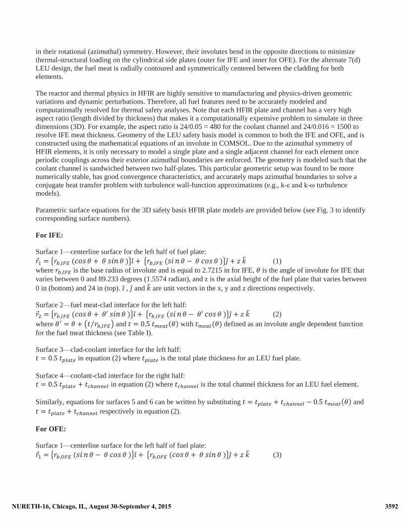
in their rotational (azimuthal) symmetry. However, their involutes bend in the opposite directions to minimize thermal-structural loading on the cylindrical side plates (outer for IFE and inner for OFE). For the alternate 7(d) LEU design, the fuel meat is radially contoured and symmetrically centered between the cladding for both elements. The reactor and thermal physics in HFIR are highly sensitive to manufacturing and physics-driven geometric variations and dynamic perturbations. Therefore, all fuel features need to be accurately modeled and computationally resolved for thermal safety analyses. Note that each HFIR plate and channel has a very high aspect ratio (length divided by thickness) that makes it a computationally expensive problem to simulate in three dimensions (3D). For example, the aspect ratio is 24/0.05 = 480 for the coolant channel and 24/0.016 = 1500 to resolve IFE meat thickness. Geometry of the LEU safety basis model is common to both the IFE and OFE, and is constructed using the mathematical equations of an involute in COMSOL. Due to the azimuthal symmetry of HFIR elements, it is only necessary to model a single plate and a single adjacent channel for each element once periodic couplings across their exterior azimuthal boundaries are enforced. The geometry is modeled such that the coolant channel is sandwiched between two half-plates. This particular geometric setup was found to be more numerically stable, has good convergence characteristics, and accurately maps azimuthal boundaries to solve a conjugate heat transfer problem with turbulence wall-function approximations (e.g., k-ε and k-ω turbulence models). Parametric surface equations for the 3D safety basis HFIR plate models are provided below (see Fig. 3 to identify corresponding surface numbers). For IFE: Surface 1—centerline surface for the left half of fuel plate:
(1) where is the base radius of involute and is equal to 2.7215 in for IFE, is the angle of involute for IFE that varies between 0 and 89.233 degrees (1.5574 radian), and z is the axial height of the fuel plate that varies between 0 in (bottom) and 24 in (top). , and are unit vectors in the x, y and z directions respectively. Surface 2—fuel meat-clad interface for the left half:
(2) where and with defined as an involute angle dependent function for the fuel meat thickness (see Table I). Surface 3—clad-coolant interface for the left half:
in equation (2) where is the total plate thickness for an LEU fuel plate. Surface 4—coolant-clad interface for the right half:
in equation (2) where is the total channel thickness for an LEU fuel element. Similarly, equations for surfaces 5 and 6 can be written by substituting and
respectively in equation (2). For OFE: Surface 1—centerline surface for the left half of fuel plate:
(3)
3592NURETH-16, Chicago, IL, August 30-September 4, 2015 3592NURETH-16, Chicago, IL, August 30-September 4, 2015

where is the base radius of involute and is equal to 5.873 in for OFE, is the angle of involute for OFE that varies between 0 and 57.366 degrees (1.0012 rad), and z is the axial height of the fuel plate that varies between 0 (bottom) and 24 in (top).
Surface 2—fuel meat-clad interface for the left half: (4)
where and with defined as an involute angle-dependent function for the fuel meat thickness (see Table I).
Equations for other OFE surfaces (from 3 to 6) can be written using the same approach used for IFE.
Table I. Variation of LEU fuel meat thickness along the length of involute for IFE and OFE
Inner Fuel Element - IFE Outer Fuel Element - OFE Distance along IFE
involute, s Fuel meat thickness,
tmeat (microns) Distance along OFE
involute, s Fuel meat thickness,
tmeat (microns) cm in microns mil cm in microns mil
0.23114 0.0910 75 2.9528 0.23439 0.0923 216 8.5039 3.07162 1.2093 407 16.0236 1.66653 0.6561 582 22.9134 6.10955 2.4053 407 16.0236 5.28646 2.0813 582 22.9134 8.02706 3.1603 193 7.5984 7.32267 2.8829 158 6.2205
Figure 3. Cut Plane Geometry for the COMSOL IFE and OFE Models.
3593NURETH-16, Chicago, IL, August 30-September 4, 2015 3593NURETH-16, Chicago, IL, August 30-September 4, 2015

At any point along the involute, angle can be determined using for both the inner and outer plates and is used to generate as a piecewise function. Once all parameterized surfaces are built inside COMSOL, they must be unionized with other primitive surfaces, such as planes and cylinders, to establish axial and radial fuel meat boundaries and to model domain enclosed between the side plates. Side plate sections corresponding to a single plate and channel are extruded from a geometric work plane located at the bottom of the fuel plate. In the end, virtual domain stitching operations are performed in COMSOL to generate physical “composite” domains for appropriate material and physics assignments. In this step, all interfacial boundaries are chosen to remain exposed allowing user-defined mesh density controls.
4. MESH, MATERIAL PROPERTIES AND SOLUTION METHOD
A unique mapped-mesh scheme with coolant boundary layers was developed to subdivide the model geometry in hexahedral linear-basis finite elements (see Fig. 4). Inside the coolant channel, ten boundary layers are used with a stretching factor of 1.2 and a first layer thickness of 0.005 mm to capture the steep gradients near the wall surface. In the longitudinal direction of the model, both the top and bottom two inches corresponding to the unfueled region of the fuel plate have eight elements each, and the central 20 inches of the fueled region has 40 elements, all distributed in an arithmetic sequence with an element ratio of four. In the radial involute direction, the model is subdivided into sixty elements with an arithmetic distribution and an element ratio of four. In the thickness direction, the model is discretized with ten elements of uniform distribution for the coolant channel (in addition to the boundary layers), two elements for the cladding on each side of the fuel plate, and eight elements for the fuel meat. This mesh density was found to be sufficient for producing mesh-converged solutions within acceptable engineering norms.
The completed mesh for the COMSOL model contains 323,520 hexahedral elements, 72,128 quadrilateral elements, 5,356 edge elements and 56 vertex elements. The model is solved for the following field variables: velocity, pressure, turbulent kinetic energy, turbulent dissipation rate, temperature and thermal stress-induced structural displacements. These variables are all described by first-order, linear finite elements. This multiphysics setup results in a total of approximately 2.8 million degrees of freedom that is solved by segregating variables using the direct PARDISO solver in COMSOL.
Figure 4. User-Controlled Hexahedral Mapped Mesh for the COMSOL IFE and OFE Models.
3594NURETH-16, Chicago, IL, August 30-September 4, 2015 3594NURETH-16, Chicago, IL, August 30-September 4, 2015

In the LEU safety basis models, temperature-dependent thermal and mechanical properties are used for all of the materials, including the fuel, clad, and water coolant. This is illustrated in the plots for U-Mo fuel properties in Fig. 5. Young’s modulus of elasticity and Poisson’s ratio for LEU fuel are assumed constant at room temperature until more information becomes available (67.75 GPa and 0.35 respectively).
(a) density, g/cc (b) heat capacity, J/g-K
(c) thermal conductivity, W/m-K (d) coefficient of thermal expansion, m/m-K
Figure 5. Temperature-Dependent Thermal Properties for the LEU U-Mo fuel.
5. MULTIPHYSICS SETUP AND BOUNDARY CONDITIONS The models are solved at HFIR steady-state operating conditions at different power levels from the beginning of reactor cycle. The following multiple physics were included in the analyses: heat conduction within the fuel plate, conjugate heat transfer from the fuel plate to the coolant channel, Reynolds averaged Navier-Stokes (k-epsilon) turbulence model for flow in the coolant channel, and thermal-expansion physics enabled for the fuel plate. The following boundary conditions (see Fig. 6) are used for both the inner and outer element models:
� inlet flow velocity in the coolant channel = 14.8 m/s (based on combined inner and outer fuel element flow rate of 13440 gpm and narrow channel thickness of 44 mil),
� log-law turbulence wall functions (law of the wall) on coolant channel boundaries, � outlet pressure of the coolant = (343 psig + 14.7 psi) – 108 psi = 249.7 psi (saturation temperature
corresponding to this outlet pressure is 204.92 oC), � inlet temperature of the coolant = 135 oF, � temperature of the top surface for the fuel and side plates is assumed to be in equilibrium with the coolant
inlet temperature = 135 oF, � similarity boundary condition (i.e., temperature and heat flux continuity) in the azimuthal direction
applied over the domain boundaries of the left and right halves of fuel plate, � temperature and heat flux continuity at the fuel and side plate interfaces,
3595NURETH-16, Chicago, IL, August 30-September 4, 2015 3595NURETH-16, Chicago, IL, August 30-September 4, 2015

� resistive thin conduction layer and boundary heat source properties for the Zr diffusion layers on each side of fuel meat,
� volumetric heat sources (W/cm3) in the fuel meat, cladding, and coolant channel � convective heat transfer through the side plate edges, and � a fixed constraint structural boundary condition over both longitudinal edges of the fuel plate.
Figure 6. Multiphysics Problem Setup for the LEU Safety Basis Analysis.
6. VOLUMETRIC HEAT SOURCES AND UNCERTAINTY FACTORS
Power densities from the explicit “plate-resolved” Monte Carlo N-particle (MCNP) transport code models are imported into COMSOL Multiphysics as lookup tables of radial and axial distances, i.e., as where r2 = x2 + y2. These discrete values are then interpolated within COMSOL using linear piecewise functions and extrapolated as constants to model boundary elements. The COMSOL LEU safety basis model considers several uncertainty factors to capture the uncertainty in reactor process conditions, fuel manufacturing uncertainties, fuel element fabrication tolerances, and analysis/correlation uncertainties. Table II is a preliminary list of selected uncertainties that are applicable to the COMSOL model. This list is a preliminary subset of all the uncertainties considered in a typical HFIR safety basis calculation for the establishment of safety limits and limiting safety system set points.
Table II. Uncertainty factors for the LEU safety basis model
Uncertainty factor Description Current LEU value U2 Uncertainty in fissile loading 1.01 U3 Uncertainty in power distribution 1.199 U4 Uncertainty in the “average” fuel concentration in
the hot plate 1.04-upper half 1.06-lower half
U18 Fuel segregation flux peaking for the fuel plate 1.27 U25 Flux peaking for fuel plate extending beyond
normal boundaries-factor applied to the bottom 0.2 inch of fuel meat
Ranges1.00-1.23 across inner plate Ranges 1.00-1.25 across outer plate
3596NURETH-16, Chicago, IL, August 30-September 4, 2015 3596NURETH-16, Chicago, IL, August 30-September 4, 2015

Figure 7. Volumetric Heat Sources (W/cm3) for the IFE and OFE at the Beginning of Cycle for Nominal 100 MW LEU Operation.
3597NURETH-16, Chicago, IL, August 30-September 4, 2015 3597NURETH-16, Chicago, IL, August 30-September 4, 2015

Uncertainty in the fissile loading, U2, is based on the value used in the HEU fuel manufacturing process and calculations. Uncertainty in the power distribution, U3, is based on a factor of 1.10 to represent uncertainty in the neutron transport (MCNP) calculations and 1.09 to represent variations in the local power density due to experiment-related flux tilts. Uncertainty factor U4 represents fuel distribution variations along the length of the plate as measured by the fuel homogeneity scanner axial scans. The HEU fuel is made to a ±12% integral accuracy along the length of each track of the fuel scans. This information is being used to represent HEU fuel axial concentration variations within the overall loading tolerance for a hot plate (overloaded with an assumed high concentration in the lower half of the plate). For the LEU analysis, a tighter integral accuracy of ±6% is used to represent axial variations in the LEU foil thickness. Uncertainty factor U18 for LEU is considered to represent two effects: (1) the effect of a locally high alloy concentration that may lead to an increased fission rate density (an uncertainty effect that is expected to be around 1.10), and (2) the effect of a nonbond on the LEU local heat flux. Because of the high degree of uncertainty in the LEU nonbond performance, the existing U18 value of 1.27 from the HEU analysis is used for LEU models. Uncertainty factor U25 is used to capture the uncertainty associated with the fuel element fabrication process wherein the plates are welded into the side plates at an axial location to ensure that the lower end of the fuel meat is at the nominal end of the core as modeled in the analysis. If a single plate were axially misaligned, its fuel could extend into the axial water-reflector flux peak region and result in a local hot spot at the end of the core. To model this effect, a U25 uncertainty distribution across the involute plate is applied to the bottom 0.2 inches of fuel meat to provide additional power peaking to the lower end of the fuel. The U25 local heat flux peaking is above that associated with the calculated local power density and its uncertainty. The U25 uncertainty distributions are not applied to the upper end of the fuel because the lower end is always the limiting location for HEU fuel. For the LEU safety basis analyses, the heat source for the fuel meat is increased by multiplying an effective uncertainty factor of Ueff (z) = U2*U3*U4(z)*U18*U25(z) to the MCNP-produced nominal 100 MW power densities. 7. USING LEGACY CORRELATIONS TO PREDICT SAFETY LIMITS In order to predict safety limits, a power factor is multiplied to the nominal 100 MW volumetric heat sources, on top of fuel uncertainty factors, for all the modeled components including fuel, clad, Zr layers, and coolant channel. The power factor is varied in steps of 0.25 between 1.0 and 2.0 to simulate equivalent conditions for 100% (= 100 MW), 125%, 150%, 175% and 200% (= 200 MW) reactor power. At each power level, steady state solutions are obtained for both IFE and OFE and are used to evaluate legacy HFIR correlations for incipient boiling, flow excursion, and burnout at the plate-coolant interface. These correlations predict margin availability at each power level. Further information on these correlations and their usage in LEU COMSOL model are provided below: 7.1 Incipient Boiling (Bergles and Rhosenow Correlation) The following correlation by Bergles and Rhosenow [4] is being used to predict the limiting wall superheat = (Tw – Tsat) for the plate-coolant interface:
3598NURETH-16, Chicago, IL, August 30-September 4, 2015 3598NURETH-16, Chicago, IL, August 30-September 4, 2015

where Tw is plate-coolant interface or clad surface temperature (oF), Tsat is coolant saturation temperature (oF) at local pressure, p (psia), and is the local clad surface heat flux (Btu/h-ft2). The wall superheat margin to incipient boiling is defined as the difference between the limiting superheat predicted using the correlation and its local COMSOL model value at each power level. The incipient boiling safety limit is defined as the power level for which the minimum value of the superheat margin reduces to zero. A linear interpolation between the available margins at the consecutive power levels is used to establish the safety limits. 7.2 Flow Excursion (Modified Saha and Zuber Correlation) For heated flows in parallel channels of HFIR, local boiling can lead to a significantly reduced flow (i.e., flow starvation) in the hot channel because of its flow diversion to other cooler non-boiling parallel channels. This flow reduction promotes more boiling in the hot channel and could lead to flow excursion (onset of flow instability) and local burnout. The following conservative form of the Saha and Zuber correlation for the limiting heat flux [5] is used to predict flow excursion limits for HFIR:
where is the coolant mass flux (kg/m2-s), is the specific heat capacity (J/kg-K), and is the local subcooling (oC), with defined as the bulk coolant temperature. The heat flux margin to flow excursion is defined as the difference between the limiting heat flux predicted using the correlation and its local COMSOL model value at each power level. The flow excursion safety limit is defined as the power level for which the minimum value of the heat flux margin reduces to zero. A linear interpolation between the available margins at the consecutive power levels is used to establish the safety limits. 7.3 Burnout (Gambill Correlation) The Gambill correlation [6] is used for HFIR core safety analyses to predict the burnout (critical) heat flux in a subcooled water system. Basic formulation of this correlation is provided in Ref. 6. This correlation has a superposition form in which summation of two terms characterize contributions from boiling in the absence of forced convection and from forced convection in the absence of boiling. The heat flux margin to burnout is defined as the difference between the limiting heat flux predicted using the correlation and its local COMSOL model value at each power level. The burnout safety limit is defined as the power level for which the minimum value of the heat flux margin reduces to zero. A linear interpolation between the available margins at the consecutive power levels is used to establish the safety limits. 8. RESULTS AND CONCLUSIONS Margins to incipient boiling (IB), flow excursion (FE) and burnout (BO) at the beginning of cycle for increasing power levels are plotted in Fig. 8. Limiting power is when the margin reduces from a positive value (indicating availability of safety margin) to zero. For IFE, these power factor limits are identified to be 1.504 (IB), 1.74 (FE) and 1.702 (BO) and for OFE, 1.045 (IB) and > 2.0 (FE, BO).
3599NURETH-16, Chicago, IL, August 30-September 4, 2015 3599NURETH-16, Chicago, IL, August 30-September 4, 2015

Figure 8. Using Legacy HFIR Correlations to Predict Safety Limits (Incipient Boiling, Flow Excursion, and Burnout) for the LEU Operation.
Three-dimensional surface plots for the fuel meat centerline temperature, the clad surface temperature, the clad surface heat flux, the clad surface pressure, the clad thermal deflection, and the bulk coolant temperature are provided in Fig. 9 for IFE and in Fig. 10 for OFE. These steady-state COMSOL results will be compared against the LEU predictions made by (1) the legacy HFIR analysis code called the Steady State Heat Transfer Code and (2) a more detailed best-estimate 3D COMSOL model.
Note that this is an ongoing project and these results are preliminary. Different designs of the LEU fuel are currently being analyzed and model enhancement continues. Therefore, the results presented may change in the future depending upon the chosen LEU fuel design, associated heat source variations, and further model developments (e.g., additional uncertainty factors, fuel swelling, pressure-induced deflections, and improved heat transfer correlations).
9. ACKNOWLEDGEMENTS
The authors would like to acknowledge that the support of this project was provided by the Reactor Conversion Program (previously known as the Global Threat Reduction Initiative, Reduced Enrichment for Research and Test Reactors Program), a program of the US Department of Energy National Nuclear Security Administration.
3600NURETH-16, Chicago, IL, August 30-September 4, 2015 3600NURETH-16, Chicago, IL, August 30-September 4, 2015

Figure 9. Steady State Safety Basis Results for the Inner Fuel Element at 100 MW.
3601NURETH-16, Chicago, IL, August 30-September 4, 2015 3601NURETH-16, Chicago, IL, August 30-September 4, 2015

Figure 10. Steady State Safety Basis Results for the Outer Fuel Element at 100 MW.
3602NURETH-16, Chicago, IL, August 30-September 4, 2015 3602NURETH-16, Chicago, IL, August 30-September 4, 2015

10. REFERENCES 1. D. Renfro, D. Chandler, D. Cook, G. Ilas, P. Jain and J. Valentine, ‘‘Preliminary Evaluation of
Alternate Designs for HFIR Low-Enriched Uranium Fuel,’’ ORNL/TM-2014/154 (2014). 2. G. Ilas and R. T. Primm III, ‘‘Low Enriched Uranium Fuel Design with Two-Dimensional Grading for the
High Flux Isotope Reactor,’’ ORNL/TM-2010/318 (2011). 3. G. Ilas, D. Chandler, B. Ade, E. Sunny, B. Betzler and D. Pinkston, ‘‘Modeling and Simulations for the
High Flux Isotope Reactor Cycle 400,’’ ORNL/TM-2015/36 (2015). 4. A. E. Bergles and W. M. Rohsenow, “The Determination of Forced-Convection Surface-Boiling Heat
Transfer,” J. Heat Transfer ASME 86365-72 (1964). 5. R. B. Rothrock, “Thermal-Hydraulic Bases for the Safety Limits and Limiting Safety System Settings for
HFIR Operation at 100 MW and 468 psig Primary Pressure, Using Specially Selected Fuel Elements,” ORNL/TM-13694 (1998).
6. W. R. Gambill, “Design Curves for Burnout Heat Flux in Forced-Convection Subcooled Light- Water Systems,” ORNL/TM-2421 (1968).
3603NURETH-16, Chicago, IL, August 30-September 4, 2015 3603NURETH-16, Chicago, IL, August 30-September 4, 2015