
Advanced modulation formats for underwater visible light ...
11
Advanced modulation formats for underwater visible light communications [Invited] Nan Chi (迟 楠)* and Meng Shi (石 蒙) Key Laboratory for Information Science of Electromagnetic Waves (MoE), Shanghai Institute for Advanced Communication and Data Science, Fudan University, Shanghai 200433, China *Corresponding author: [email protected] Received July 5, 2018; accepted November 1, 2018; posted online December 4, 2018 In this paper, we present a detailed comparison of applying three advanced modulation formats including car- rierless amplitude and phase modulation (CAP), orthogonal frequency division multiplexing (OFDM), and dis- crete Fourier transform spread orthogonal frequency division multiplexing (DFT-S OFDM) in underwater visible light communication (UVLC) systems. Cascaded post-equalization schemes are suggested to compensate the system impairments. For the first time, a two-level post-equalizer is presented to mitigate the nonlinear effect and improve the system performance of UVLC. The first post-equalization is based on a novel recursive least square Volterra. These modulation formats are all experimentally demonstrated with corresponding digital sig- nal processing (DSP) algorithms. The experimental results show that single carrier modulations including CAP and DFT-S OFDM can outperform OFDM. Our experiment results show that up to 3 Gb/s over a 1.2 m under- water visible light transmission can be achieved by using DFT-S OFDM 64QAM and CAP-64. The measured bit error rate is well under the hard decision-forward error correction (HD-FEC) threshold of 3.8 × 10 -3 . OCIS codes: 060.4080, 060.4230. doi: 10.3788/COL201816.120603. Visible light communication (VLC) has become an attrac- tive and promising technology for high-speed indoor wire- less communication. Unlike radio frequency (RF) wireless communication, VLC utilizes the already installed light emitting diode (LED) as data transmitters and can be ap- plied in environments where RF is not necessarily allowed, such as airplanes, military facilities, and underwater com- munication. In VLC, many advanced modulation formats are investigated to achieve high-speed transmission successfully [ 1– 26] . Table 1 summarizes some achievements in the VLC sys- tems in recent years. All of these show the feasibility of these advanced modulation formats in the VLC system. In 2008, the Visible Light Communications Association (VLCC), established in Japan in October 2003, researched and realized a 2 km indoor visible light transmission based on OOK modulation of 1.022 Mb/s [ 1] . In the same year, Oxford University increased the speed to 80 Mb/s with post-equalization at a distance of 10 cm [ 3] . In 2010, the German HHI began to study indoor visible light transmis- sion based on discrete multitone (DMT) modulation, initially using a white LED to achieve a 513 Mb/s over 30 cm transmission [ 6] . By 2012, the German Heinrich Hertz Institute (HHI) had made advancements with RGB LEDs and wavelength division multiplexing (WDM) to achieve a 1.25 Gb/s over 10 cm transmission [ 8] . In the same year, Italy’s Scuola Superiore Sant’Anna (SSSUP) adopted the optimized DMT modulation method and RGB WDM to achieve 1.5 Gb/s in a single-LED single-channel over a 10 cm transmission, and the RGB three-color WDM multiplexing rate reached 3.4 Gb/s [ 10] . In 2014, SSSUP in Italy continued the study of DMT modulation, using a common RGBY lamp and WDM to achieve a downlink of 5.6 Gb/s and an uplink of 1.5 Gb/s over a 1.5 m trans- mission [ 13] . In 2015, the University of Cambridge used the μLED and pre-equalization method based on PAM4 modulation to achieve an indoor 2 Gb/s over 60 cm trans- mission [ 17] . Wang et al. [ 16] in Fudan University achieved an 8 Gb/s RGBY four-color LED-based WDM VLC system by utilizing high-order carrierless amplitude and phase (CAP) modulation and a hybrid post-equalizer. In 2016, Oxford University used RGB LEDs to perform direct cur- rent optical orthogonal frequency-division multiplexing (DCO-OFDM) modulation based on WDM technology. At the same time, pre-equalization, bit loading, and other technologies were implemented to optimize the system and achieve a 1.5 m transmission of 10.4 Gb/s [ 20] . In 2018, Zhu et al. [ 21] achieved a 10.72 Gb/s VLC system over 1 m utiliz- ing quadrature amplitude modulation or discrete multitone (QAM-DMT) modulation and RGBYC silicon substrate LED. From the comprehensive domestic and foreign research status, we can see that after more than 10 years of develop- ment, VLC has received more and more attention from all over the world, and an upsurge of VLC research and industrialization has also been set off internationally. At the same time, from the perspective of the development trend from 2010 to now, the key technology for realizing high-speed VLC has become the most important direction for the future development of VLC. How to break through the system bandwidth limitation and effectively compen- sate the system for multiple impairments is a major issue in improving the VLC capacity and transmission dis- tance. The new high spectral efficiency modulation and COL 16(12), 120603(2018) CHINESE OPTICS LETTERS December 10, 2018 1671-7694/2018/120603(11) 120603-1 © 2018 Chinese Optics Letters
Transcript of Advanced modulation formats for underwater visible light ...

Advanced modulation formats for underwater visiblelight communications [Invited]
Nan Chi (迟 楠)* and Meng Shi (石 蒙)
Key Laboratory for Information Science of Electromagnetic Waves (MoE), Shanghai Institute for AdvancedCommunication and Data Science, Fudan University, Shanghai 200433, China
*Corresponding author: [email protected] July 5, 2018; accepted November 1, 2018; posted online December 4, 2018
In this paper, we present a detailed comparison of applying three advanced modulation formats including car-rierless amplitude and phase modulation (CAP), orthogonal frequency division multiplexing (OFDM), and dis-crete Fourier transform spread orthogonal frequency division multiplexing (DFT-S OFDM) in underwatervisible light communication (UVLC) systems. Cascaded post-equalization schemes are suggested to compensatethe system impairments. For the first time, a two-level post-equalizer is presented to mitigate the nonlinear effectand improve the system performance of UVLC. The first post-equalization is based on a novel recursive leastsquare Volterra. These modulation formats are all experimentally demonstrated with corresponding digital sig-nal processing (DSP) algorithms. The experimental results show that single carrier modulations including CAPand DFT-S OFDM can outperform OFDM. Our experiment results show that up to 3 Gb/s over a 1.2 m under-water visible light transmission can be achieved by using DFT-S OFDM 64QAM and CAP-64. The measured biterror rate is well under the hard decision-forward error correction (HD-FEC) threshold of 3.8 × 10⁻³.
OCIS codes: 060.4080, 060.4230.doi: 10.3788/COL201816.120603.
Visible light communication (VLC) has become an attrac-tive and promising technology for high-speed indoor wire-less communication. Unlike radio frequency (RF) wirelesscommunication, VLC utilizes the already installed lightemitting diode (LED) as data transmitters and can be ap-plied in environments where RF is not necessarily allowed,such as airplanes, military facilities, and underwater com-munication. In VLC, many advanced modulation formatsare investigated to achieve high-speed transmissionsuccessfully[1–26].Table 1 summarizes some achievements in the VLC sys-
tems in recent years. All of these show the feasibility ofthese advanced modulation formats in the VLC system.In 2008, the Visible Light Communications Association
(VLCC), established in Japan in October 2003, researchedand realized a 2 km indoor visible light transmission basedon OOK modulation of 1.022 Mb/s[1]. In the same year,Oxford University increased the speed to 80 Mb/s withpost-equalization at a distance of 10 cm[3]. In 2010, theGerman HHI began to study indoor visible light transmis-sion based on discrete multitone (DMT) modulation,initially using a white LED to achieve a 513 Mb/s over30 cm transmission[6]. By 2012, the German Heinrich HertzInstitute (HHI) had made advancements with RGB LEDsand wavelength division multiplexing (WDM) to achievea 1.25 Gb/s over 10 cm transmission[8]. In the same year,Italy’s Scuola Superiore Sant’Anna (SSSUP) adopted theoptimized DMT modulation method and RGB WDMto achieve 1.5 Gb/s in a single-LED single-channel overa 10 cm transmission, and the RGB three-color WDMmultiplexing rate reached 3.4 Gb/s[10]. In 2014, SSSUPin Italy continued the study of DMT modulation, using
a common RGBY lamp and WDM to achieve a downlinkof 5.6 Gb/s and an uplink of 1.5 Gb/s over a 1.5 m trans-mission[13]. In 2015, the University of Cambridge used theμLED and pre-equalization method based on PAM4modulation to achieve an indoor 2 Gb/s over 60 cm trans-mission[17]. Wang et al.[16] in Fudan University achieved an8 Gb/s RGBY four-color LED-based WDM VLC systemby utilizing high-order carrierless amplitude and phase(CAP) modulation and a hybrid post-equalizer. In 2016,Oxford University used RGB LEDs to perform direct cur-rent optical orthogonal frequency-division multiplexing(DCO-OFDM) modulation based on WDM technology.At the same time, pre-equalization, bit loading, and othertechnologies were implemented to optimize the system andachieve a 1.5 m transmission of 10.4 Gb/s[20]. In 2018, Zhuet al.[21] achieved a 10.72 Gb/s VLC system over 1 m utiliz-ing quadrature amplitude modulation or discrete multitone(QAM-DMT) modulation and RGBYC silicon substrateLED.
From the comprehensive domestic and foreign researchstatus, we can see that after more than 10 years of develop-ment, VLC has received more and more attention fromall over the world, and an upsurge of VLC research andindustrialization has also been set off internationally.At the same time, from the perspective of the developmenttrend from 2010 to now, the key technology for realizinghigh-speed VLC has become the most important directionfor the future development of VLC. How to break throughthe system bandwidth limitation and effectively compen-sate the system for multiple impairments is a majorissue in improving the VLC capacity and transmission dis-tance. The new high spectral efficiency modulation and
COL 16(12), 120603(2018) CHINESE OPTICS LETTERS December 10, 2018
1671-7694/2018/120603(11) 120603-1 © 2018 Chinese Optics Letters

equalization techniques are the key methods to solve theabove problems. Domestic and foreign research instituteshave already carried out a lot of fruitful research work herewhich can be seen from Table 1. We have grasped the ma-jor opportunities for the development of VLC, closelylinked the frontiers of VLC research at home and abroadand conducted relevant research work on advanced modu-lation and equalization technologies in high-speed VLCsystems. All of these show the feasibility of these advancedmodulation formats in the VLC system.Nowadays, underwater wireless information transmis-
sion is an emerging area that needs to be investigated.Wang et al. proposed the single-photon avalanche diode(SPAD) detection algorithm and optimal detectionthreshold for underwater VLC and obtained some simula-tion results[27]. Then we thought about combining VLCand underwater transmission. There are three main partsthat lead to severe nonlinearity for an underwater VLC(UVLC) system. First, the system performance wouldbe destroyed by the limited modulation bandwidthand the inherent nonlinearity of LEDs. Second, the
underwater channel would induce absorption, scattering,and diffraction effects to the optical signal and the signalwould be attenuated. Absorption is the process in whichphotons are converted into other forms of energy and thusare completely annihilated. Scattering is the processwherein the photon changes its direction as a result ofits interaction with substances existing in the water envi-ronment[28]. Then received signals would be attenuatedthat in turn reduce the signal-to-noise ratio (SNR) andinduce nonlinearity of the UVLC system. Finally, the non-linearity at the receiver optoelectronic conversion andelectrical amplifier also influences the performance.
What is more, generally on-off-keying (OOK)digital modulation was used in past underwater transmis-sion[29]. To realize high-speed UVLC transmission, multi-level QAM modulation must be considered subject to thestringent bandwidth of the LED. This kind of QAMmodulation requires good linearity because relatively largenonlinearity will induce severe intersymbol interference(ISI) and will result in failure detection. Therefore, thenonlinearity mitigation is one of the significant challenges
Table 1. Summary of Research Results of VLC Systems
Transmitter Modulation Formats Equalization Receiver Data Rate Distance Research Group Year
White LED OOK / Sensor 1022 b/s 2 km Japan VLCC[1] 2008
White LED OOK Pre PIN 40 Mb/s 2 m Oxford[2] 2008
White LED OOK Post PIN 80 Mb/s 10 cm Oxford[3] 2008
White LED DMT Post PIN 101 Mb/s 1 cm Germany HHI[4] 2008
White LED DMT Post PIN 230 Mb/s 70 cm Germany HHI[5] 2009
White LED DMT Post APD 513 Mb/s 30 cm Germany HHI[6] 2010
RGB LED DMT Post APD 803 Mb/s 12 cm Germany HHI[7] 2011
RGB LED DMT Post APD 1.25 Gb/s 10 cm Germany HHI[8] 2012
RGB LED DMT Post APD 2.1 Gb/s 10 cm Italy SSSUP[9] 2012
RGB LED DMT Post APD 3.4 Gb/s 10 cm Italy SSSUP[10] 2012
White LED CAP Post PIN 1.1 Gb/s 23 cm Taiwan JiaoTong University[11]
2012
RGB LED CAP Post PIN 3.22 Gb/s 25 cm Taiwan JiaoTong University[12]
2013
RGBY LED DMT Post PIN 5.6 Gb/s 1.5 m Italy SSSUP[13] 2014
RGB LED SC Pre/Post APD 4.22 Gb/s 1 m Fudan University[14] 2014
RGB LED CAP Pre/Post PIN 4.5 Gb/s 2 m Fudan University[15] 2015
RGB LED CAP Pre/Post PIN 8 Gb/s 1 m Fudan University[16] 2015
μLED PAM4 Pre/Post APD 2 Gb/s 60 cm Cambridge University[17] 2015
RGB LED PAM8 Pre/Post PIN 3.375 Gb/s 1 m Fudan University[18] 2016
RGBY LED DMT Pre/Post PIN 9.51 Gb/s 1 m Fudan University[19] 2016
RGB LED DCO-OFDM Pre/Post PIN 10.4 Gb/s 1.5 m Oxford[20]
RGBYC siliconsubstrate LED
QAM-DMT Pre/Post PIN 10.72 Gb/s 1 m Nanchang University &Fudan University[21]
2018
COL 16(12), 120603(2018) CHINESE OPTICS LETTERS December 10, 2018
120603-2

for the UVLC system using high-order QAM modulation.The environment in UVLC is more complex, which needsadvanced modulation formats to resist the loss of complexenvironments, make the full use of modulated bandwidth,achieve high-speed transmission, as well as obtain a stableand reliable system.Table 2 summarizes some achievements in the UVLC
systems in recent years. Recent research in LED UVLChas mostly focused on utilizing different modulationtechniques to increase both the data transmission rateand the link distance. In 2010, Doniec et al. of the NationalUniversity of Singapore achieved 0.6 Mb/s over 9 m byusing six blue LEDs as a transmitter, an avalanche photo-diode (APD) as a receiver and digital pulse integrationmodulation (DPIM) as the modulation format[30]. In2014, Cossu et al. utilized two LED arrays and thenon-return-to-zero (NRZ) 8 b/10 b format to achieve12.5 Mb/s over a 2.5 m distance. In 2016, Xu et al. fromZhejiang University adopted OFDM modulation formatsand a compact blue LED, and finally obtained a data rateof 161 Mb/s over 2 m. In 2017, a data rate of 200 Mb/ssystem was achieved by Tian et al. in Fudan University.They selected OOK, a simple modulation format, andcombined it with a μLED to transmit signals over 5.4 m.In 2018, Kong et al. in Zhejiang University proposed anunderwater wireless optical communication (UWOC) sys-tem using an arrayed transmitter/receiver and opticalsuperimposition-based pulse amplitude modulation with4 levels (PAM4). The bit error rate (BER) under theFEC threshold can be reached for the 12.288 Mb/sPAM4 signal after transmitting through a 2 m underwaterchannel. In the same year, Wang et al. in Fudan Universityproposed an underwater VLC system utilizing QAM-DMTand multi-PIN reception to do the maximum-ratio combin-ing (MRC) receiving. The data rate of 2.175 Gb/s transmis-sion over 1.2 m was achieved successfully.
As a promising solution, the Volterra series-basedequalizer plays significant role in mitigating the nonline-arity in the VLC[31]. In our group’s previous work, a blindpost-equalization scheme called the cascaded Volterramodified multi-modulus algorithm was employed anddemonstrated to compensate for linearity and mitigatethe LED nonlinearity in the CAP modulation-basedVLC system[32].
We choose three advanced modulation formats whichare CAP, orthogonal frequency-division multiplexing(OFDM) and DFT-S OFDM modulation for UVLC. Tothe best of our knowledge, the performance comparisonof these three modulation formats has not been reported,especially for UVLC. Such comparison is of great valueconsidering the requirements of high-speed and validtransmission for underwater applications.
In this Letter, we present a comprehensive comparisonof advanced modulation formats including CAP, OFDM,and DFT-S OFDM. We also discuss the correspondingdigital signal processing (DSP). For each format, apost-equalizer structure consisting of two cascaded stagesis suggested. For the first time, a post-equalizer based onnovel recursive least square (RLS)- Volterra is presentedto mitigate the nonlinear effect and improve the systemperformance of UVLC. The Volterra is used to compen-sate the nonlinearity and the RLS algorithm is used to up-date the tap coefficients of Volterra. Then these threetypical advanced modulation formats are all realized atthe same bit rate of 3 Gbit/s. The comparison is carriedout to evaluate the performance of each modulation for-mat in terms of peak-to-average power ratio (PAPR),nonlinear equalization, LED current, optical power, andpeak-to-peak voltage. Finally, CAP-64 and DFT-SOFDM are successfully achieved over 1.2 m of UVLCtransmission under a hard-decision forward errorcorrection (HD-FEC) threshold of 3.8 × 10⁻³. However,
Table 2. Summary of Research Results of LED UVLC Systems
TransmitterModulationFormats Equalization Receiver Data Rate
Distance(m)
Authors andResearch Group Year
Six blue LEDs DPIM / APD 0.6 Mb/s 9 Doniec et al., NationalUniversity of Singapore[30]
2010
Two-LEDarrays
NRZ8 b/10 b
/ APD 12.5 Mb/s 2.5 Cossu et al., ScuolaSuperiore Sant’AnnaVTeCIP, Italy[33]
2014
Compact blueLED
OFDM Pre/Post PIN 161 Mb/s 2 Xu et al., ZhejiangUniversity[34]
2016
μLED OOK / PIN/APD
200 Mb/s 5.4 Tian et al., FudanUniversity[35]
2017
Two blue LEDs PAM4 / MPPC(containSPADs)
12.288 Mb/s 2 Kong et al., ZhejiangUniversity[36]
2018
Blue siliconsubstrate LED
QAM-DMT Pre/Post PIN 2.175 Gb/s 1.2 Wang et al., FudanUniversity[37]
2018
COL 16(12), 120603(2018) CHINESE OPTICS LETTERS December 10, 2018
120603-3

DFT-S OFDM performs best among these three formats.The remainder of this Letter is organized as follows. TheDSP and the detailed two-level post-equalizer for threemodulation formats are presented first. Then the experi-mental setup and results in the UVLC case and VLC caseare shown. Next is the conclusion.In this part, we describe the signal generation flow and
recovery flow of CAP-64, OFDM 64QAM, and DFT-SOFDM 64QAM. All of these three modulation formatsneed mapping and upsampling in the generation process.While CAP has an extra need for IQ separation and shap-ing filters at the cost of convolution. DFT-S requires anextra fast Fourier transform (FFT) and inverse fast Fou-rier transform (IFFT); and the first-level post-equalizerfor each format is the RLS-Volterra in the time domain.The second-level post-equalizer for CAP is RLS-Volterrain the time domain, however, for DFT-S and OFDM it iszero-forcing (Z-F) in the frequency domain. Figure 1(a)shows a schematic diagram of the CAP-64 system. Atthe transmitter, the data is first mapped into complexsymbols of the 64QAM signal. Then data is upsampledby a factor of 4. An I/Q separation is used to form aHilbert pair and a square-root-raised-cosine shaping filterof a roll-off factor of 0.105 is used as a shaping filter. Dur-ing the offline process, the signal is sent into the matchedfilter to separate the in-phase and quadrature compo-nents. After synchronization, the first post-equalization,downsampled, and second post-equalization are utilizedin order. Finally, the BER performance of the final datais measured after the post-equalization and de-mappingprocess.Figure 1(b) shows a schematic diagram of the OFDM
64QAM system. At the transmitter, the data is firstmapped into complex symbols of a 64QAM signal. Thendata is converted from serial to parallel. After 4 timesupsampling in the frequency domain, an IFFT is usedto generate the OFDM signal with 256 subcarriers. Next,a 32 sample cyclic prefix (CP) is added to alleviate the ISI.Parallel to serial conversion and upconversion are con-ducted subsequently. During the offline process, thesynchronized signal is processed by downconversion, firstpost-equalization, serial to parallel conversion, cyclic pre-fix removal, downsampling, and FFT followed by a secondpost-equalization. The second post-equalizer is based on
the Z-F method. The number of training sequences is20. The BER performance of the final data is measuredafter the de-mapping process.
Figure 1(c) shows a schematic diagram of the DFT-SOFDM 64QAM system. The process flow is similar to thatof OFDM in Fig. 2. The difference is that DFT-S adds an-other N-point FFT before normal OFDM processing atthe transmitter. However, at the receiver, another IFFTtransform needs to be conducted correspondingly foroffline processing. The parameters of the DFT-S are thesame as we used for OFDM. The length of CP is 32and the number of the subcarrier is 256. The length ofthe training sequences is 20.
Figure 2 presents the structure of the RLS-Volterrapost-equalizer. Volterra is used to compensate nonlineareffect[32]. When taking the performance of equalizationand computational complexity into consideration, onlythe second-order terms are selected[38]. However, we selectthe third-order term here considering the more severenonlinearity in the UVLC system. The equation can beexpressed as
yðnÞ¼ylðnÞþynlðnÞ
¼XNi−1
ki¼0
wki ðnÞ·xðn−k1Þ
þXN 2−1
k1¼0
XN 2−1
k2¼k1
wk1k2ðnÞ·xðn−k1Þ·xðn−k2Þ
þXN 3−1
k1¼0
XN 3−1
k2¼k1
XN 3−1
k3¼k2
wk1k2k3ðnÞxðn−k1Þxðn−k2Þxðn−k3Þ;
(1)
where xðnÞ is the input signal of the filter at time n. Theoutput of yðnÞ is the sum of the linear equalization ylðnÞand nonlinear equalization ynlðnÞ. N 1, N 2, and N 3 are thetap numbers of the linear and the nonlinear equalizers.wki , wk1k2 , and wk1k2k3 are the weights of the linear and non-linear equalizers, respectively. Nonlinear filters based onthe Volterra series also require an updated algorithm toupdate the tap coefficients of the filter. Here, the RLS al-gorithm[15] is selected because of the faster convergencethan the least mean squares algorithm. The combination
Fig. 1. Schematic diagram: (a) CAP-64 system; (b) OFDM 64QAM system; (c) DFT-S OFDM 64QAM system.
COL 16(12), 120603(2018) CHINESE OPTICS LETTERS December 10, 2018
120603-4

of the two-order Volterra series and RLS algorithm, calledRLS-Volterra, can mitigate the linear and nonlinear dam-age better. The experiment is performed later by utilizingRLS-Volterra post-equalizer.Then we compare three advanced formats in terms
of simulation and experiment. First, to further studythe effect of PAPR, we evaluate the PAPR of the threemodulation formats, as shown in Fig. 3. The figure showsthe relationship between the complementary cumulativedistribution function (CCDF) and PAPR. Compared withthe other two modulation formats, OFDM 64QAM hasthe largest PAPR, while DFT-S OFDM is the secondlarger. It needs to note that the roll-off factor of thesquare-root-raised-cosine shaping filter will affect thePAPR performance of CAP modulation. In order to showthe PAPR performance of different values of the roll-offfactor, Fig. 3 is drawn by selecting three different roll-off factors (i.e., 0.105, 0.205, and 0.305). From the figure,we find that PAPR will decrease with the value of the roll-off factor and increases when the value of roll-off factor issmaller than 0.4 as analyzed in Ref. [39]. When the valueof the roll-off factor is 0.105, the CAP modulation has thelargest PAPR compared to the other roll-off factor values.However, it is the closest to DFT-S OFDM. To make thesystem performance comparison fair, the roll-off factoradopted for CAP modulation is 0.105 for our later experi-ment in this Letter.
We get further comparison by means of a practical ex-periment. In this experiment, the comparison is carriedout under fair conditions with the same experimentalsetup. The experimental setup of the UVLC system andVLC system is shown in Fig. 4. At the transmitter, theoriginal binary bit sequence is first mapped into complexsymbols of QAM to form CAP, OFDM, and DFT-SOFDM signals, respectively. In the experiment, datawas input into the channel of an arbitrary waveformgenerator (AWG, Tektronix AWG710B) to generateelectrical signals. Then, signals passed through aself-designed bridge-T base pre-equalizer (hardware pre-equalization) to compensate for high-frequency attenua-tion of the channel. Followed by an electrical amplifier(EA, 25 dB gain) and a DC bias tee, the signals are coupledto the blue chip (457 nm) of an RGBYC silicon substrateLED lamp (researched by Nanchang University)[21] via anAD-DC coupler to drive the LED to emit light to generatean optical signal. The underwater transmission distance inthe UVLC system and free-space transmission distance inthe VLC system are 1.2 m.
At the receiver, the lens is placed in front of the receiverto focus light. A photodiode (PIN, Hamamatsu 10784) isused to detect the received light signals by converting theoptical signals to electrical signals. Amplifiers and digitalstorage oscilloscopes (OSC, Agilent DSO54855A) are usedto amplify and quantize the received signals so that theacquired data can be processed offline. In offline process-ing, each format follows their own schematic diagram.Finally, the signals are de-mapped to obtain the originalbit sequence and the system BER performance iscalculated.
In the experiment, in order to compare three advancedformats on the same condition fairly, the same bandwidthis utilized. The sample rate of the AWG is set at 2 G Sa/sall the time. Due to the upsample factor being 4, the band-width is 500 Mbaud, and the order for the three advancedformats is 6. As a result, the maximum achievable trans-mission data rate is 3 Gb/s. The subcarriers of DFT-SOFDM and OFDM are 256.
Specifically, there are some differences among three ad-vanced modulation formats in offline post-equalization.Figure 5 shows the block diagram of the post-equalizationin the CAP, DFT-SOFDM, andOFDM systems. As for thepost-equalizer, we conducted two-level post-equalization inthe experiment. The first-level post-equalization for threeadvanced modulation formats is the RLS-Volterra equali-zation algorithm, which is conducted in the time domainafter data synchronization. Second-level post-equalizationfor CAP is the RLS-Volterra in the time domain afterdownconversion and downsampling, while for DFT-Sand OFDM is the Z-F algorithm in the frequency domainafter removing CP, downsampling, and FFT. The second-level post-equalization is normal for each modulation for-mat. The innovation for the post-equalizer is the employingof the first-level RLS-Volterra algorithm.
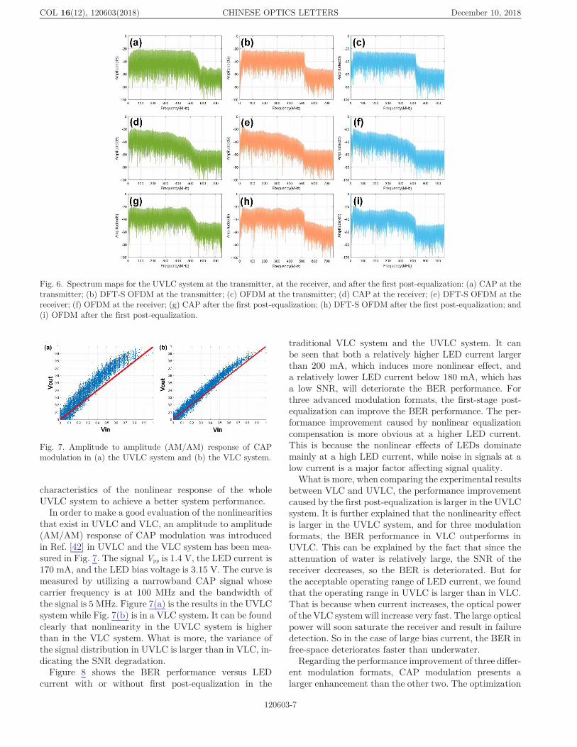
To investigate the effect of first-level post-equalizationhere, the spectrum maps at the transmitter, at the
Fig. 2. Structure of the RLS-Volterra post-equalizer.
Fig. 3. CCDF versus PAPR of CAP-64, OFDM 64QAM, andDFT-S OFDM 64QAM.
COL 16(12), 120603(2018) CHINESE OPTICS LETTERS December 10, 2018
120603-5

receiver, and after the first post-equalization in theCAP, DFT-S, and OFDM systems are presented in Fig. 6.From the figure, we can find that after transmission, thesignal is destroyed especially at high frequency, and afterthe first post-equalization in the time domain, the spec-trum map in the frequency domain is compensated. Thenthe signals can be optimized for the following DSPmethod.When considering the main source of nonlinearity in
UVLC compared to traditional VLC, we focus on the ef-fect of water. As a result, the comparison of three formatsin both the UVLC and VLC systems has been investi-gated. The performance results are shown in Figs. 7–10.
The latest expression of the underwater channelonly takes optical pass loss into consideration[40,41]. Thereal underwater VLC channel includes the frequencyresponse of electronic devices (signal amplifier, pre-equalizer, LED driver, LED, etc.) and an optical channel.For the whole UVLC system, the expression of the under-water channel includes the transmitter, the underwaterchannel and the receiver. The nonlinearity in the UVLCsystem that arose from the LED, the transmitter drivingcircuits, PIN photodetector, and the receiver amplifica-tion circuits may introduce extra nonlinear noise andcan cause detrimental effects to the signal reception.Therefore, it is an essential issue to measure the statistic
Fig. 4. Experimental setup of (a), (b) the underwater VLC system and (c) the free-space VLC system.
Fig. 5. Block diagram of post-equalization in the CAP, DFT-S OFDM, and OFDM systems.
COL 16(12), 120603(2018) CHINESE OPTICS LETTERS December 10, 2018
120603-6
characteristics of the nonlinear response of the wholeUVLC system to achieve a better system performance.In order to make a good evaluation of the nonlinearities
that exist in UVLC and VLC, an amplitude to amplitude(AM/AM) response of CAP modulation was introducedin Ref. [42] in UVLC and the VLC system has been mea-sured in Fig. 7. The signal Vpp is 1.4 V, the LED current is170 mA, and the LED bias voltage is 3.15 V. The curve ismeasured by utilizing a narrowband CAP signal whosecarrier frequency is at 100 MHz and the bandwidth ofthe signal is 5 MHz. Figure 7(a) is the results in the UVLCsystem while Fig. 7(b) is in a VLC system. It can be foundclearly that nonlinearity in the UVLC system is higherthan in the VLC system. What is more, the variance ofthe signal distribution in UVLC is larger than in VLC, in-dicating the SNR degradation.Figure 8 shows the BER performance versus LED
current with or without first post-equalization in the
traditional VLC system and the UVLC system. It canbe seen that both a relatively higher LED current largerthan 200 mA, which induces more nonlinear effect, anda relatively lower LED current below 180 mA, which hasa low SNR, will deteriorate the BER performance. Forthree advanced modulation formats, the first-stage post-equalization can improve the BER performance. The per-formance improvement caused by nonlinear equalizationcompensation is more obvious at a higher LED current.This is because the nonlinear effects of LEDs dominatemainly at a high LED current, while noise in signals at alow current is a major factor affecting signal quality.
What is more, when comparing the experimental resultsbetween VLC and UVLC, the performance improvementcaused by the first post-equalization is larger in the UVLCsystem. It is further explained that the nonlinearity effectis larger in the UVLC system, and for three modulationformats, the BER performance in VLC outperforms inUVLC. This can be explained by the fact that since theattenuation of water is relatively large, the SNR of thereceiver decreases, so the BER is deteriorated. But forthe acceptable operating range of LED current, we foundthat the operating range in UVLC is larger than in VLC.That is because when current increases, the optical powerof the VLC systemwill increase very fast. The large opticalpower will soon saturate the receiver and result in failuredetection. So in the case of large bias current, the BER infree-space deteriorates faster than underwater.
Regarding the performance improvement of three differ-ent modulation formats, CAP modulation presents alarger enhancement than the other two. The optimization
Fig. 6. Spectrum maps for the UVLC system at the transmitter, at the receiver, and after the first post-equalization: (a) CAP at thetransmitter; (b) DFT-S OFDM at the transmitter; (c) OFDM at the transmitter; (d) CAP at the receiver; (e) DFT-S OFDM at thereceiver; (f) OFDM at the receiver; (g) CAP after the first post-equalization; (h) DFT-S OFDM after the first post-equalization; and(i) OFDM after the first post-equalization.
Fig. 7. Amplitude to amplitude (AM/AM) response of CAPmodulation in (a) the UVLC system and (b) the VLC system.
COL 16(12), 120603(2018) CHINESE OPTICS LETTERS December 10, 2018
120603-7

for OFDM and DFT-S OFDM is relatively smaller than forCAP, which can be explained that for these twomodulationformats, the major nonlinear equalization compensation isconducted by the second post-equalization (i.e., Z-F equali-zation). The impact of the second post-equalization forthese two formats will be analyzed in Fig. 11. Here, theparameters of the first post-equalization are set so thatthe order of Volterra is 2 and the number of taps ofRLS is 9. As for CAP, whose second post-equalization isalso RLS-Volterra, the parameters are set so that the orderof Volterra is 2 and the number of taps of RLS is 43.For a nonlinear system, we can use the Volterra
series for characterization and use it for nonlinear compen-sation[15,16]. To get a further elaboration of the degree ofnonlinearity in the VLC and the UVLC systems, we also
compare the performance of three advanced modulationformats using Volterra for nonlinear compensation. We in-vestigate the effect of the order of Volterra in the first post-equalization. When the order of Volterra is changed, thenumber of taps of RLS needs to be modified correspond-ingly to get an optimal BER value. The results are shownin Fig. 9. The working point is chosen at 1 V Vpp, 190 mAcurrent for both the UVLC and VLC systems. We can alsosee that BER in the VLC system is better than in theUVLC system. The BER performance decreases as the or-der of Volterra increases. When the Volterra series is fur-ther increased, the BER performance tends to be flat. Fromthe figure, we can find that the inflection point of theVolterra series is 2. For the UVLC system, it is necessaryto consider more than 3 orders of the Volterra series.
Fig. 8. BER versus LED current in (a) the traditional VLC system and (b) the UVLC system.
Fig. 9. BER versus order of Volterra in the UVLC and VLC systems with (a) CAP, (b) DFT-S, and (c) OFDM.
Fig. 10. BER versus number of taps in the UVLC and VLC systems with (a) CAP, (b) DFT-S, and (c) OFDM.
COL 16(12), 120603(2018) CHINESE OPTICS LETTERS December 10, 2018
120603-8

For our following experiment, the order of Volterra is set as2 when taking both the BER performance and computa-tional complexity into consideration.It indicates that besides the signal-to-signal beating in-
terference (SSBI) and beat interference between signals,there is a certain 3-order nonlinear effect, including thecross-interference term among the three signals, thesquare term of the signals, and cross-interference of othersignals. The BER performance in the UVLC system ishigher than in the VLC system. These show clearly thatin the UVLC system the nonlinearity is more severe thanin the traditional VLC system. Experimental results showthat the VLC system can achieve lower BER at the sametransmission rate, and the UVLC system has more severenonlinearity compared to a free-space channel. Also, theDFT-S OFDM modulation format performs better in ei-ther the UVLC or VLC system.Since nonlinearity would cause greater ISI, we also dis-
cuss the comparison of the number of taps for three for-mats in the UVLC and the VLC systems. Figure 10shows the BER versus number of taps in UVLC andVLC systems for three formats. The working point is alsoat 1 V Vpp, 190 mA current. The BER in UVLC system ishigher than in the VLC system. From the figure, we canfind that optimal taps number is 9 for UVLC system and 5for VLC system. The number of taps required for UVLCsystem is higher than for the VLC system. It shows thatISI induced by nonlinearity increases, and the current bitand adjacent bits have a deeper range of influence.The comparison between the UVLC system and the tra-
ditional VLC system has been studied in Figs. 7–10. Allthe experimental results show that UVLC has higher non-linearity compared to the VLC system. Next, we focus onthe performance of three advanced modulation formats inthe UVLC system.We compared the BER performance using sparse pilot
to do linear interpolation for channel equalization andfound that the performance would deteriorate. The resultsare shown in Fig. 11. Figure 11(a) shows the BER perfor-mance with different numbers of pilot. Figures 11(b) and11(c) show the channel curve estimated by linear Z-F(number of pilot ¼ 2) and nonlinear Z-F (number of
pilot ¼ 256). It shows that the minimum number ofpilot for the second post-equalization is 32. At thesame time, it means that the Z-F method compensatesnonlinearity for OFDM and DFT-S OFDM. Therefore,nonlinearity compensation is still very necessary forOFDM and DFT-S OFDM modulation formats. Butthe main gain is obtained by applying second nonlinearpost-equalization. The combination of two-level post-equalization (i.e., RLS-Volterra and Z-F) will optimizethe system performance better.
We compare the BER performance under different LEDoptical power in the UVLC system. The results are shownin Fig. 12. From the figure, only CAP and DFT-S canachieve the HD-FEC threshold, and the dynamic rangefor CAP is 72.4 mW while for DFT-S it is 94.8 mW.DFT-S achieves a broadening of 22.4 mW in the dynamicrange for optical power. The inset figures are the constel-lation diagrams. They show clearly that DFT-S performsthe best.
Figure 13 shows the BER versus peak-to-peak voltagesof the LED in the CAP, DFT-S OFDM, and OFDMsystems. Under the HD-FEC, the dynamic range ofCAP is 0.7 V and the dynamic range of DFT-S is0.83 V. Compared to the CAP modulation format, theenlargement of 0.13 V in Vpp is successfully realized byapplying the DFT-S modulation format. It means thatDFT-S modulation format allows the system’s BER tostay below the HD-FEC threshold in a wider range ofVpp, thus improving the system stability.
To investigate the influence of bandwidth, Fig. 14shows the BER performance versus bandwidth in theUVLC system. It can be found that when the bandwidthis less than 550 MHz the DFT-S OFDM modulationformat performs best. It is worth noting that since theDFT-S OFDM is a single-carrier scheme, it is more sensi-tive to the ISI. Therefore, DFT-S OFDM cannot outper-form all the time. When the bandwidth increases up to560 MHz (i.e., the ISI influence is more severe), theDFT-S OFDM format performs worst. However, theOFDM has the lowest BER at 560 MHz.
Fig. 11. BER performance of the 2nd post-equalization forOFDM and DFT-S OFDM in the UVLC system: (a) with differ-ent number of pilot, (b) channel curve when the number of pilotis 2, and (c) channel curve when the number of pilot is 256.
Fig. 12. BER versus LED optical power of CAP, DFT-S, andOFDM systems.
COL 16(12), 120603(2018) CHINESE OPTICS LETTERS December 10, 2018
120603-9

In this paper, a comprehensive comparison is presentedamong CAP-64, OFDM 64QAM, and DFT-S OFDM64QAM with the RLS-Volterra post-equalizer in anUVLC system and traditional VLC system. We presenta two-level hybrid post-equalizer to compare againstboth the linear distortion and nonlinear distortion. The firstpost-equalization is based on a novel RLS-Volterra. Theperformance improvement created by the first post-equalization is larger in the UVLC system compared tothat in the VLC system. The UVLC system has a moresevere nonlinearity than the traditional VLC system.The comparison is carried out to evaluate the performanceof each modulation format in terms of PAPR, LED current,nonlinear equalization, optical power, and peak-to-peakvoltage. A transmitting rate of 3.0 Gb/s over 1.2 m under-water VLC transmission is easily achieved by CAP-64 andDFT-S OFDM 64QAM. From the experimental results,DFT-S OFDM outperforms both the CAP and OFDM sig-nals. It shows that DFT-S OFDM is a potential candidatein the future underwater VLC system.
This work was supported by the National Natural Sci-ence Foundation of China (NSFC) (No. 61571133) andthe National Key Research and Development Programof China (No. 2017YFB0403603).
References1. A. Nakajima, N. Sako, M. Kamemura, Y. Wakayama, A. Fukuzawa,
H. Sugiyama, and N. Okada, in Proceedings of the InternationalConference on Space Optical Systems and Applications (2012), p. 12.
2. H. Le Minh, D. O’Brien, G. Faulkner, L. Zeng, K. Lee, D. Jung, andY. Oh, IEEE Photon. Technol. Lett. 20, 1243 (2008).
3. H. Le Minh, D. O’Brien, G. Faulkner, L. Zeng, K. Lee, D. Jung, andY. Oh, in Proceedings of the European Conference on OpticalCommunication ECOC (2008), p. 1.
4. J. Grubor, S. Randel, K. D. Langer, and J. W.Walewski, in Proceed-ings of 6th International Symposium on Communication Systems,Networks and Digital Signal Processing CNSDSP (2008) p. 165.
5. J. Vucic, C. Kottke, S. Nerreter, A. Büttner, K.-D. Langer, and J. W.Walewski, IEEE Photon. Technol. Lett. 21, 1511 (2009).
6. J. Vucic, C. Kottke, S. Nerreter, K.-D. Langer, and J. W. Walewski,J. Lightwave Technol. 28, 3512 (2010).
7. J. Vucic, C. Kottke, K. Habel, and K.-D. Langer, in Proceedings ofOptical Fiber Communication Conference (2011), paper OWB6.
8. C. Kottke, J. Hilt, K. Habel, J. Vučić, and K.-D. Langer, in Proceed-ings of European Conference on Optical Communication ECOC(2012), paper We.3.B.4.
9. G. Cossu, A. M. Khalid, P. Choudhury, R. Corsini, and E.Ciaramella, in Proceedings of European Conference on OpticalCommunication ECOC (2012), paper P4. 16.
10. G. Cossu, A. M. Khalid, P. Choudhury, R. Corsini, and E.Ciaramella, Opt. Express 20, B501 (2012).
11. F.-M. Wu, C.-T. Lin, C.-C. Wei, C.-W. Chen, H.-T. Huang, andC.-H. Ho, IEEE Photon. Technol. Lett. 24, 1730 (2012).
12. F.-M. Wu, C.-T. Lin, C.-C. Wei, C.-W. Chen, Z.-Y. Chen, and K.Huang, in Proceedings of Optical Fiber Communication ConferenceOFC (2013), paper OTh1G.4.
13. G. Cossu, A. Wajahat, R. Corsini, and E. Ciaramella, in Proceedingsof European Conference on Optical Communication ECOC (2014),paper We.3.6.4.
14. Y. Wang, X. Huang, J. Zhang, Y. Wang, and N. Chi, Opt. Express22, 15328 (2014).
15. Y. Wang, X. Huang, L. Tao, J. Shi, and N. Chi, Opt. Express 23,13626 (2015).
16. Y. Wang, L. Tao, X. Huang, J. Shi, and N. Chi, IEEE Photon. J. 7,7904507 (2015).
17. X. Li, N. Bamiedakis, X. Guo, J. J. D. McKendry, E. Xie, R. Ferreira,E. Gu, M. D. Dawson, R. V. Penty, and I. H. White, in Proceedingsof European Conference on Optical Communication ECOC (2015),paper 0640.
18. N. Chi, M. Zhang, Y. Zhou, and J. Zhao, Opt. Express 24, 21663(2016).
19. N. Chi, J. Shi, Y. Zhou, Y.Wang, J. Zhang, and X. Huang, in Proceed-ings of Photonics Society Summer Topical Meeting Series (2016), p. 4.
20. H. Chun, S. Rajbhandari, G. Faulkner, D. Tsonev, E. Xie, K.McKendry, E. Gu, M. Dawson, D. O’Brien, and H. Hass, J. Light-wave Technol. 34, 3047 (2016).
21. X. Zhu, F. Wang, M. Shi, N. Chi, J. Liu, and F. Jiang, in Proceedingsof Optical Fiber Communications Conference and Exhibition (2018),paper M3K.3.
22. N. Chi, H. Haas, M. Kavehrad, T. D. C. Little, and X. Huang, inProceedings of IEEE Wireless Communications (2015), p. 5.
23. Y. Wang, Y. Wang, N. Chi, J. Yu, and H. Shang, Opt. Express 21,1203 (2013).
24. Z. Wang, M. Zhang, S. Chen, and N. Chi, Chin. Opt. Lett. 15,030602 (2017).
25. M. Shi, F. Wang, M. Zhang, Z. Wang, and N. Chi, in Proceedings ofIEEE International Conference on Communications Workshops(2017), p. 337.
Fig. 13. BER versus peak-to-peak voltages (Vpp) of the LED inCAP, DFT-S OFDM, and OFDM systems.
Fig. 14. BER performance versus bandwidth of three advancedmodulation formats in the UVLC system.
COL 16(12), 120603(2018) CHINESE OPTICS LETTERS December 10, 2018
120603-10

26. H. Qian, S. J. Yao, S. Z. Cai, and T. Zhou, IEEE Photon. J. 6,7901508 (2014).
27. C. Wang, H. Yu, and Y. Zhu, IEEE Photon. J. 8, 7906311 (2017).28. Y. Wang, L. Tao, X. Huang, J. Shi, and N. Chi, IEEE Photon. J. 7,
7907907 (2015).29. L. Tao, H. Tan, C. Fang, and N. Chi, in IEEE Progress in Electro-
magnetic Research Symposium (2016), p. 4863.30. H. M. Oubei, C. Shen, A. Kammoun, E. Zedini, K. Park, X. Sun, G.
Liu, C. H. Kang, T. K. Ng, M. Alouini, and B. S. Ooi, Jpn. J. Appl.Phys. 57, 08PA06 (2018).
31. M. Kong, Y. Chen, R. Sarwar, B. Sun, Z. Xu, J. Han, J. Chen, H. Qin,and J. Xu, Opt. Express 26, 3087 (2018).
32. F. Wang, Y. Liu, F. Jiang, and N. Chi, Opt. Commun. 425, 106(2018).
33. D. F. Zhang, Y. J. Zhu, T. Wang, Z. J. Tian, and Y. Y. Zhang, Appl.Mech. Mater. 511–512, 357 (2014).
34. M. Doniec, I. Vasilescu, M. Chitre, C. Detweiler, M. Hoffmann-Kuhnt, and D. Rus, in Oceans IEEE Conference (2010), p. 1.
35. G. Cossu, R. Corsini, A. M. Khalid, S. Balestrino, A. Coppelli, A.Caiti, and E. Ciaramella, in International Workshop on OpticalWireless Communications Conference (2014), p. 11.
36. J. Xu, M. Kong, A. Lin, Y. Song, X. Yu, F. Qu, J. Han, and N. Deng,Opt. Commun. 369, 100 (2016).
37. P. Tian, X. Liu, S. Yi, Y. Huang, S. Zhang, X. Zhou, L. Hu, L. Zheng,and R. Liu, Opt. Express 25, 1193 (2017).
38. G. Stepniak, J. Siuzdak, and P. Zwierko, IEEE Photon. Technol.Lett. 25, 1597 (2013).
39. S. Daumont, R. Basel, and Y. Louet, in 3rd International Symposiumon Communications, Control and Signal Processing (2008), p. 841.
40. M. Elamassie, F. Miramirkhani, andM. Uysal, in IEEE InternationalConference on Communications Workshops (2018), p. 1.
41. H. L. Minh, D. O’Brien, G. Faulkner, L. Zeng, K. Lee, D. Jung, Y.Oh, and E. T. Won, IEEE Photon. Technol. Lett. 21, 1063 (2009).
42. Y. Zhou, C.Wang, J. Zhang, J. Zhao, M. Zeng, and N. Chi, inOpticalFiber Communications Conference and Exhibition (2017),paper W2A.40.
COL 16(12), 120603(2018) CHINESE OPTICS LETTERS December 10, 2018
120603-11


![All-Optical Signal Processing for High Spectral Efficiency ... · SE, the large bandwidth and multilevel modulation formats [5]. Coherent optical systems using multilevel modulation](https://static.fdocuments.in/doc/165x107/5ecf8c9b3dff6463180c0404/all-optical-signal-processing-for-high-spectral-efficiency-se-the-large-bandwidth.jpg)


![Chapter 4 Advanced Modulation Formats · modulation format [1], which has received increasing attention owing to its greater spectra efficiency (SE) than binary formats, such as that](https://static.fdocuments.in/doc/165x107/5ecf8c9a3dff6463180c0401/chapter-4-advanced-modulation-formats-modulation-format-1-which-has-received.jpg)
