
Advanced Lab Course - Technische Fakultät · micro-electro-mechanical system (MEMS) ... Ternary...
12
Advanced Lab Course Cantilever Deflection Method M204 As of: 30.03.2015 Aim: Characterization of shape memory alloy (SMA) martensite transformation after introduction of a third element on the NiTi matrix, using CDM (Cantilever Deflection Method). Content 1 INTRODUCTION 1 2 OVERVIEW OVER MARTENSITE TRANSFORMATIONS 1 3 TERNARY SHAPE MEMORY ALLOYS 2 3.1 Shape memory alloys for thin film composites 2 3.2 Functional principle of thin film substrate composite 4 3.3 Work output of shape memory composites 5 4 EXPERIMENTAL 6 4.1 Fundamentals of cantilever bending 6 4.2 Result interpretation and software operation 8 4.3 Procedure 10 5 REPORT 10 6 REFERENCES 11
Transcript of Advanced Lab Course - Technische Fakultät · micro-electro-mechanical system (MEMS) ... Ternary...

Advanced Lab Course
Cantilever Deflection Method M204
As of: 30.03.2015 Aim: Characterization of shape memory alloy (SMA) martensite transformation after introduction of a third element on the NiTi matrix, using CDM (Cantilever Deflection Method).
Content
1 INTRODUCTION 1
2 OVERVIEW OVER MARTENSITE TRANSFORMATIONS 1
3 TERNARY SHAPE MEMORY ALLOYS 2
3.1 Shape memory alloys for thin film composites 2
3.2 Functional principle of thin film substrate composite 4
3.3 Work output of shape memory composites 5
4 EXPERIMENTAL 6
4.1 Fundamentals of cantilever bending 6
4.2 Result interpretation and software operation 8
4.3 Procedure 10
5 REPORT 10
6 REFERENCES 11

M204: Cantilever Deflection Method
1 Introduction Differential scanning calorimetry (DSC) and tensile tests are conventionally used as characterization methods for freestanding TiNi films. Results of such tensile tests show that the elongation, fracture stress and yield stress are comparerable to those of bulk material. For micro-electro-mechanical system (MEMS) applications, the TiNi films are usually deposited on Si or other related substrates (e.g. Mo). For this specific purpose several methods can be used such as curvature [1], electrical resistivity [2], bulge [3] and cantilever bending measurements [4]. For this experiment we will use cantilever bending to characterize NiTi martensite transformation after introduction of a third element on the NiTi matrix.
2 Overview over martensite transformations The shape memory effect (SME) is closely related to the martensitic transformation (MT), which can be, simplified, described as a diffusionless phase transformation in solids, in which atoms move cooperatively and often by a shear-like mechanism. Usually the parent phase (a high temperature phase) is cubic, and the martensite (a lower temperature phase) has a lower symmetry. The transformation is schematically shown in Fig. 1. When the temperature is lowered below a critical one, MT starts with a shearlike mechanism. The martensite in the region A and in region B has the same structure, but the orientations are different. These are called the correspondence variants of the martensites.
Figure 1: A simplified model of martensitic transformation.
1

M204: Cantilever Deflection Method
Since the martensite has a lower symmetry, many variants can be formed from the same parent phase. Now, if the temperature is raised and the martensite becomes unstable, the reverse transformation occurs, and if it is crystallographically reversible, the martensite reverts to the parent phase in the original orientation.
In Fig. 2, some characteristic temperatures will be defined. MS, Mf, are the temperatures, where upon cooling martensite formation starts and finishes, respectively. AS, Af, are the temperatures, where upon heating austenite formation starts and finishes, respectively.
Figure 2: Typical DSC curve. The diagram shows the transformation temperatures of the austenite, R-phase and martensite phase. The start of the peak indicates the beginning of the transformation (start s). At the end of the peak the whole sample is transformed (finish f).
More information regarding the shape memory effect and further properties (e.g su-perelasticity) can be found in the script shape memory alloy and in the literature given in the reference list.
3 Ternary Shape memory alloys 3.1 Shape memory alloys for thin film composites
Martensite phase transformation temperature for a binary shape memory (TiNi) system is mainly influenced by the stoichiometry. High content of Ni the transformation temperature will decrease and at low content the transformation temperature will increase, providing two possibilities of different martensitic transformations: the two-step B2-R-phase-B19’ transformation and the direct B2-B19’. Usually, the B2-R-phase transformation is preferred for actuator applications, since it exhibits a very narrow hysteresis and since it is less sensitive to deviations in stoichiometry and lattice defects. Figure 3 shows the TiNi austenitic crystallographic structure.
2

M204: Cantilever Deflection Method
Figure 3: TiNi austenitic crystallographic structure [5] a) Body centered cubic unit cell, b) 4 Body centered cubic unit cell and c) Tetragonal face centered, that after martensite transformation will transform to monoclinic unit cell.
Introduction of a third element on the NiTi matrix affects the transformation temperatures, and thus the shape recovery temperatures of Ti-Ni alloys. For example, the substitution of vanadium, chromium, manganese or aluminum for titanium lowers the transformation temperatures, as shown in figure 4. The substitution of cobalt, iron or copper for nickel also lowers the martensite transformation temperatures. [5]
Figure 4: Effects of third transition metal additives upon Ms.
Figure 5 is the equilibrium Ti-Ni-Cu phase diagram at 1143K.[6] In Ti-Ni-Cu alloys in which Cu is substituted for Ni, the parent phase remains as a single B2 phase up to 30 at% Cu. If the content of Cu is reduced to an amount between 5 and 15 at% is observed a two-step transformation (from cubic (B2) to orthorhombic (B19), and then to monoclinic (B19’)). Increasing Cu content, the transformation start temperature of B2-B19 does not change, but that of the B19-B19’ decreases. In alloys of copper contents exceeding 15at% the second transformation does not occur.
3

M204: Cantilever Deflection Method
Figure 5: Ti-Ni-Cu phase diagram at 1143K.
3.2 Functional principle of thin film substrate composite
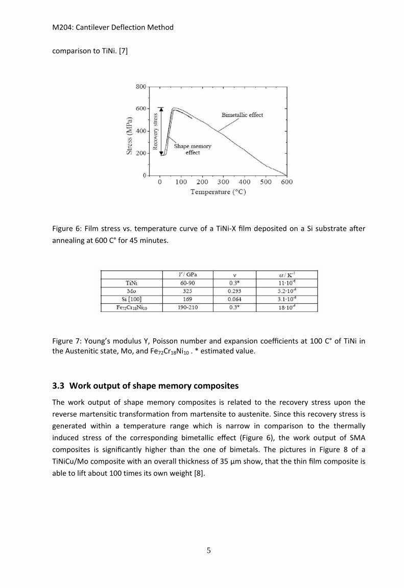
In contrast to freestanding films, SMA films deposited on metallic foils or on Si wafers are not able to provide strain changes of about 8 percent, since the substrate material cannot stand these large strains without plastic deformation. However, many substrate materials stand large stresses. Mo, for example, has a yield stress of about 600 MPa. This high stress value can be applied to SMA films, if the thermal expansion coefficients of film and substrate differ significantly, the Young’s modulus of the substrate is higher than the one of the SMA and the corresponding composites are treated at temperatures above the recrystallization temperature of the SMA. After the heat treatment, upon cooling, the thermally induced stress in the composite increases until the SMA reaches the martensitic start temperature Ms. As a consequence, the increasing stress in the film substrate composite leads to the bending of the film composite. Upon further cooling, the SMA subsequently undergoes the martensitic transformation. Due to the generation of preferentially oriented martensitic variants upon this transformation, the thermally induced stress in the SMA is reduced significantly and the bending of the composite is reversed. Figure 6 shows the stress-temperature curve of a TiNi-X film on a Si substrate after heat treatment at 600 C°. The linear part of the curve corresponds to the bimetallic effect and the hysteresis to the shape memory effect. Reheating the composite to the austenitic state can regenerate the stress of about 400 MPa due to the martensitic transformation. The stress that remains in the martensitic state is related to the superelastic plateau stress of the SMA. Therefore, the usable magnitude of the effect is restricted to the stress difference between the yield stress of the austenite of about 600 MPa and the superelastic plateau stress of the SMA. This stress difference is called recoverable stress according to the constrained recovery effect. Since there are substrate materials with thermal expansion coefficients higher as well as lower than those of TiNi-based alloys, it is possible to perform compressive as well as tensile stresses within the SMA films. Fig. 7 lists the essential thermo-mechanical properties of TiNi as well as the used Mo, Si and steel substrates. Mo for this experiment was chosen due to its low expansion coefficient in
4
M204: Cantilever Deflection Method
comparison to TiNi. [7]
Figure 6: Film stress vs. temperature curve of a TiNi-X film deposited on a Si substrate after annealing at 600 C° for 45 minutes.
Figure 7: Young’s modulus Y, Poisson number and expansion coefficients at 100 C° of TiNi in the Austenitic state, Mo, and Fe72Cr18Ni10 . * estimated value.
3.3 Work output of shape memory composites
The work output of shape memory composites is related to the recovery stress upon the reverse martensitic transformation from martensite to austenite. Since this recovery stress is generated within a temperature range which is narrow in comparison to the thermally induced stress of the corresponding bimetallic effect (Figure 6), the work output of SMA composites is significantly higher than the one of bimetals. The pictures in Figure 8 of a TiNiCu/Mo composite with an overall thickness of 35 µm show, that the thin film composite is able to lift about 100 times its own weight [8].
5

M204: Cantilever Deflection Method
Figure 8: Pictures of a TiNiCu/Mo composite in the martensitic and austenitic state, respectively. The thickness of the TiNiCu film is 10 µm and the thickness of the Mo 25 µm.
4 Experimental 4.1 Fundamentals of cantilever bending
To characterize SMA films deposited on metallic foil or Si wafers we will use a method called cantilever deflection. This method is based, as explained in section 3.2, on the thermal induced stress of the analyzed material and is used to characterize the phase transformation in a SMA. Figure 9 shows a sketch of the equipment used and the measurement.
Based on the fundamentals of work showed in Figure 9 deflection D of a sample with length Lb can be calculated using:
4bL xDa∆
= (1)
where x∆ corresponds to the laser dislocation on the PSD surface and a the distance
Figure 9: Cantilever bending sketch with its work fundamentals.
6

M204: Cantilever Deflection Method
between PSD and sample. Based on the calculation realized by Timoshenko [9], we can calculate the shape memory film/substrate stress σ using the equations bellow:
( )(1 )
filmsub subfilm
film
ET
vσ β α= ∆ −
−: (2)
2 (1 )3 ( )
(1 )film sub film
b sub filmsub film film
E v dD L T
E v dα α
−= ∆ −
− (3)
where E is the Elastic Modulus, ν the Poisson ration, α the thermal coefficient and d the thickness. Combining eq. 1, 2 and 3, we can define the influence of the film stress filmσ on the
PSD surface x∆ .
21(12. . ) (1 )
film sub
b film film
E d xa L v d
σ = ∆−
(4)
Now if we substitute the laser dislocation on the PSD surface Δx by the measured voltage
ΔU on the PSD we can calculate the stress on a shape memory film/substrate.
21(12. . ) (1 )
film sub x
b film film U
E d d Ua L v d d
σ = ∆−
(5)
Figure 10: Cantilever bending equipment assembly
7

M204: Cantilever Deflection Method
4.2 Result interpretation and software operation
It is shown in the figure below a standard profile phase transformation in shape memory thin film alloy deposited on a substrate. The onsets are related to (Ms) martensite start, (As) austenite start, (Mf ) martensite finish, (Af ) austenite finish, ΔT hysteresis width and Δσ the stress difference between austenite and martensite
Figure 11: Stress-temperature standard profile for a shape memory film deposited on a substrate. ( 8M ) is the martensite start, ( 8A ) is the austenite start, ( fM ) martensite finish, (
fA ) austenite finish, T∆ is the hysteresis width and σ∆ is the stress difference between austenite and martensite.
8

M204: Cantilever Deflection Method
Summary of the software command control
Figure 12: Software command control
Where,
Haake ein = Cooler ON Haake aus = Cooler OFF Balkenlaenge = Sample length Verb. Dicke = Composite thickness Balkenbreite = Sample width Schichtdicke = Film thickness Substrat = Substrate material Kuehlen = to cool Verb. Dicke = Composite thickness Regel status = Test status Heizrate = Heat rate Zyklen = Cycles
9

M204: Cantilever Deflection Method 4.3 Procedure
• Measure the sample provided by the supervisor (Thickness, width, length). • Sample disassembly/assembly :
o Close vacuum valve. o Switch off vacuum pump . o Ventilate the vacuum chamber using the air valve. o Release the screws on the sample holder flange. o Take care with thermocouple and other cables!!!!!!! o Place the sample provided by the supervisor on the sample holder. o Measure the distance between the clamp and the mirror (sample length). o Place the whole sample holder inside the vacuum chamber and tighten the
screws. • Switch on the laser and choose on the Keithley device: local and channel 5. • Choose local mode on the Keithley multimeter • Choose channel 5 on the multimeter
• • Figure 13: Keithley 2000 Multimeter: Local and channel buttons • Close the air valve, open the vacuum valve and switch on the vacuum pump. • The laser should be adjusted in order to center the spot to the middle of the PSD.
This step should be explained by the supervisor during the lab. • Choose a file name on the software. • Enter the sample dimension, temperature range and heating rate in the corresponding
text fields. • Start measurement.
5 Report • Describe both experiments • Evaluate the measurement by plotting the results in a graphic (stress [MPa] vs.
temperature [C]). In this plot you should indicate : 8M , fM , 8A and fA . • Plot the data provided by the supervisor and compare it with the measured results.
• Based on this comparison write (scientifically arguments) the reasons for the differ-ence between both plots.
• Describe the effect observed in the TiNiCu/Mo experiment (Figure 8).
10

M204: Cantilever Deflection Method
6 References [1] K. Otsuka and C.M. Wayman, Shape memory materials, Cambridge University Press. [2] H.Funakubo, Shape memory alloys, Gordon and Breach Science Publishers. [3] P. Krulevitch, A.P. Lee, P.B. Ramsey, J.C. Trevino, J. Hamilton, M.A.M.A. Northrup, Thin film shape-memory alloy micro-actuators, J. MEMS 5 (1996) 270-282. [4] D.S. Grummon, J.P. Zhang, T.J. Pence, Relaxation and recovery of extrinsic stress in sputtered titanium-nickel thin films on (1 0 0)-Si, Mater. Sci. Eng. A 273-275 (1999) 722-726. [5] S. Moyne, C. Poilane, K. Kitamura, S. Miyazaki, P. Delobelle, C.Lexcellent, Analysis of the thermomechanical behavior of Ti-Ni shape-memory alloy thin films by bulging and nanoindentation procedures, Mater. Sci. Eng. A273-A275 (1999) 727-732. [5]H.Xu, I. Mller, Effect of mechanical vibration, heat treatment and ternary addition on the hysteresis in shape memory alloy, J.Mat.Sc., Vol26(1991)1473-1477. [6] F.J.J van Loo, G.F Bastin and A.J.H Leenen, Journal of the Less Common Metals, Vol.57, Issue 1, (1978) 111-121. [7] B. Winzek, Tobias Sterzl, Holger Rumpf, Nikolai Botkin, Eckhard Quandt, Thin film shape memory composites, Center of advanded European studies and research (Caesar), Bonn. [8]K.Adachi, K.Shoji and Y.Tagawa, Src. Metall.,21(1987)453. [9]S.Timoshenko, Analysis of Bi-metal thermostats, Jounal of the optical society of America and review of Scientific Intruments, Vol.11, No1-6 (1925)233-255.
11


![Rafid Ahmed - db.in.tum.dedb.in.tum.de/.../seminarHauptspeicherdbs/slides/04-cuckoo-hashing.pdf · Fakultät für Informatik Technische Universität München Cuckoo Hashing[1] : 4](https://static.fdocuments.in/doc/165x107/5dd1338bd6be591ccb64b526/rafid-ahmed-dbintumdedbintumdeseminarhauptspeicherdbsslides04-cuckoo-.jpg)


