Advanced Integration Module Installation in Cisco 2600...
16
Quick Start Guide Advanced Integration Module Installation in Cisco 2600 Series, Cisco 3600 Series, and Cisco 3700 Series Routers 1 Required Tools and Equipment 2 Opening the Chassis 3 Installing AIMs 4 Applying the AIM Label to the Chassis 5 Closing the Chassis 6 Verifying AIM Installation 7 Where to Go Next 8 Obtaining Documentation 9 Documentation Feedback 10 Obtaining Technical Assistance 11 Obtaining Additional Publications and Information
Transcript of Advanced Integration Module Installation in Cisco 2600...
Quick Start Guide
Advanced Integration Module Installation in Cisco 2600 Series,Cisco 3600 Series, and Cisco 3700 Series Routers
1 Required Tools and Equipment
2 Opening the Chassis
3 Installing AIMs
4 Applying the AIM Label to the Chassis
5 Closing the Chassis
6 Verifying AIM Installation
7 Where to Go Next
8 Obtaining Documentation
9 Documentation Feedback
10 Obtaining Technical Assistance
11 Obtaining Additional Publications and Information
1 Required Tools and EquipmentTo install an advanced integration module (AIM) in a Cisco modular router chassis, you need the following tools and equipment:
• Number 2 Phillips screwdriver or small flat-blade screwdriver
• 1/4-inch nut driver
• 3/16-inch open-end wrench
• Torx-15 screwdriver (for installation in Cisco 3660 only)
• ESD-preventive wrist strap
• Tape for DC circuit breaker handle
Safety InformationFor safety information that you need to know before working on your Cisco router, refer to the Regulatory Compliance andSafety Information document that accompanied your router and is accessible online on Cisco.com. For information about
accessing this document, see the “Where to Go Next” section on page 12 and the “Obtaining Documentation” section on
page 13.
Warning Only trained and qualified personnel should be allowed to install or replace this equipment. To see translations ofthe warnings that appear in this publication, refer to the Regulatory Compliance and Safety Information documentthat accompanied this device.
Warning Two people are required to lift the chassis. Grasp the chassis underneath the lower edge and lift with both hands.To prevent injury, keep your back straight and lift with your legs, not your back. To prevent damage to the chassisand components, never attempt to lift the chassis with the handles on the power supplies or on the interfaceprocessors, or by the plastic panels on the front of the chassis. These handles were not designed to support theweight of the chassis. To see translations of the warnings that appear in this publication, refer to the RegulatoryCompliance and Safety Information document that accompanied this device.
Caution Electrostatic discharge (ESD) can damage equipment and impair electrical circuitry. Always follow ESD prevention
procedures when removing and replacing cards.
2 Opening the ChassisTo install or remove an AIM, you have to open the chassis. There are three different chassis types:
• Chassis of 1 rack unit (RU) height—has separable top and bottom halves (most Cisco 2600 series routers)
• Chassis of 2-RU height with removable cover—has flat cover with separating hinge (some Cisco 2600, Cisco 3600, and
Cisco 3700 series routers)
• Chassis with plug-in CPU/mainboard—all have 2 or more RU height (some Cisco 3600 and Cisco 3700 series routers)
Refer to the procedure that applies to your router. For more detailed instructions, refer to the online AIM installation procedure
on cisco.com.
The following warning applies to routers that use a DC power supply:
Warning Before performing any of the following procedures, ensure that power is removed from the DC circuit. To ensurethat all power is OFF, locate the circuit breaker on the panel board that services the DC circuit, switch the circuitbreaker to the OFF position, and tape the switch handle of the circuit breaker in the OFF position. To seetranslations of the warnings that appear in this publication, refer to the Regulatory Compliance and SafetyInformation document that accompanied this device.
2
The following warning applies to all routers:
Warning Before opening the chassis, disconnect the telephone-network cables to avoid contact with telephone-networkvoltages. To see translations of the warnings that appear in this publication, refer to the Regulatory Complianceand Safety Information document that accompanied this device.
Opening a Chassis of 1-RU HeightPerform this procedure with electrical power to the router turned OFF, with network interface cables disconnected, and with
the router removed from its mounting rack.
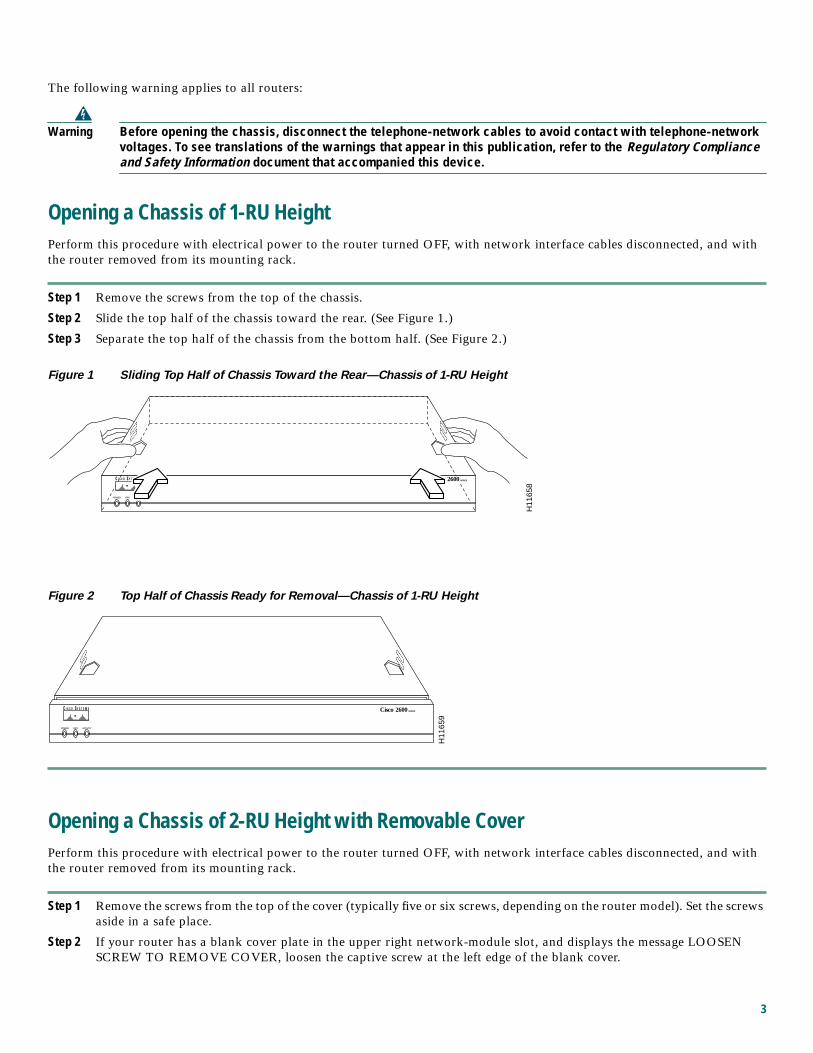
Step 1 Remove the screws from the top of the chassis.
Step 2 Slide the top half of the chassis toward the rear. (See Figure 1.)
Step 3 Separate the top half of the chassis from the bottom half. (See Figure 2.)
Figure 1 Sliding Top Half of Chassis Toward the Rear—Chassis of 1-RU Height
Figure 2 Top Half of Chassis Ready for Removal—Chassis of 1-RU Height
Opening a Chassis of 2-RU Height with Removable CoverPerform this procedure with electrical power to the router turned OFF, with network interface cables disconnected, and with
the router removed from its mounting rack.
Step 1 Remove the screws from the top of the cover (typically five or six screws, depending on the router model). Set the screws
aside in a safe place.
Step 2 If your router has a blank cover plate in the upper right network-module slot, and displays the message LOOSEN
SCREW TO REMOVE COVER, loosen the captive screw at the left edge of the blank cover.
POWER RPS ACTIVITY
H11
658
Cisco 2600 SERIES
H11
659
POWER RPS ACTIVITY
Cisco 2600 SERIES
3
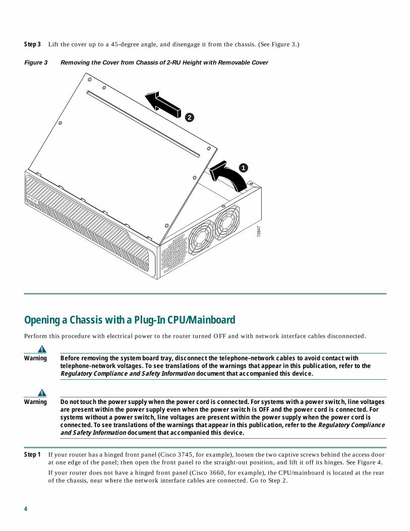
Step 3 Lift the cover up to a 45-degree angle, and disengage it from the chassis. (See Figure 3.)
Figure 3 Removing the Cover from Chassis of 2-RU Height with Removable Cover
Opening a Chassis with a Plug-In CPU/MainboardPerform this procedure with electrical power to the router turned OFF and with network interface cables disconnected.
Warning Before removing the system board tray, disconnect the telephone-network cables to avoid contact withtelephone-network voltages. To see translations of the warnings that appear in this publication, refer to theRegulatory Compliance and Safety Information document that accompanied this device.
Warning Do not touch the power supply when the power cord is connected. For systems with a power switch, line voltagesare present within the power supply even when the power switch is OFF and the power cord is connected. Forsystems without a power switch, line voltages are present within the power supply when the power cord isconnected. To see translations of the warnings that appear in this publication, refer to the Regulatory Complianceand Safety Information document that accompanied this device.
Step 1 If your router has a hinged front panel (Cisco 3745, for example), loosen the two captive screws behind the access door
at one edge of the panel; then open the front panel to the straight-out position, and lift it off its hinges. See Figure 4.
If your router does not have a hinged front panel (Cisco 3660, for example), the CPU/mainboard is located at the rear
of the chassis, near where the network interface cables are connected. Go to Step 2.
7284
7
1
2
4
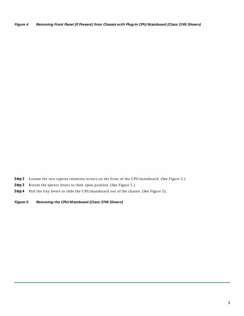
Figure 4 Removing Front Panel (If Present) from Chassis with Plug-In CPU/Mainboard (Cisco 3745 Shown)
Step 2 Loosen the two captive retention screws on the front of the CPU/mainboard. (See Figure 5.)
Step 3 Rotate the ejector levers to their open position. (See Figure 5.)
Step 4 Pull the tray levers to slide the CPU/mainboard out of the chassis. (See Figure 5).
Figure 5 Removing the CPU/Mainboard (Cisco 3745 Shown)
5
3 Installing AIMsPerform the following procedure for each AIM to be installed. To complete this procedure, you need a number 2 Phillips
screwdriver or a flat-blade screwdriver (for Cisco 3660 only, a Torx-15 screwdriver), and a 1/4-inch nut driver. For more
detailed instructions, refer to the online AIM installation procedure on Cisco.com.
Note Some Cisco routers have one AIM connector (AIM slot 0), and some have two AIM connectors (AIM slot 0 and AIM
slot 1). If there are two AIM slots, you can install one or two compression AIMs, but only one encryption AIM (in
either slot).
Note Some AIMs are provided with two mounting kits that contain different standoffs. For a router with a 1-RU chassis, use
the mounting kit that contains a plastic standoff that snaps in at both ends. For all other routers, use the mounting kit
that contains a plastic standoff with one threaded end.
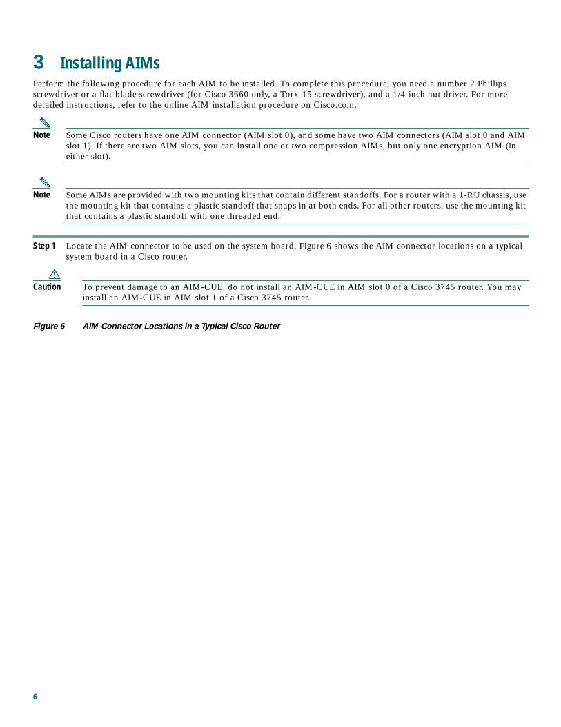
Step 1 Locate the AIM connector to be used on the system board. Figure 6 shows the AIM connector locations on a typical
system board in a Cisco router.
Caution To prevent damage to an AIM-CUE, do not install an AIM-CUE in AIM slot 0 of a Cisco 3745 router. You may
install an AIM-CUE in AIM slot 1 of a Cisco 3745 router.
Figure 6 AIM Connector Locations in a Typical Cisco Router
6
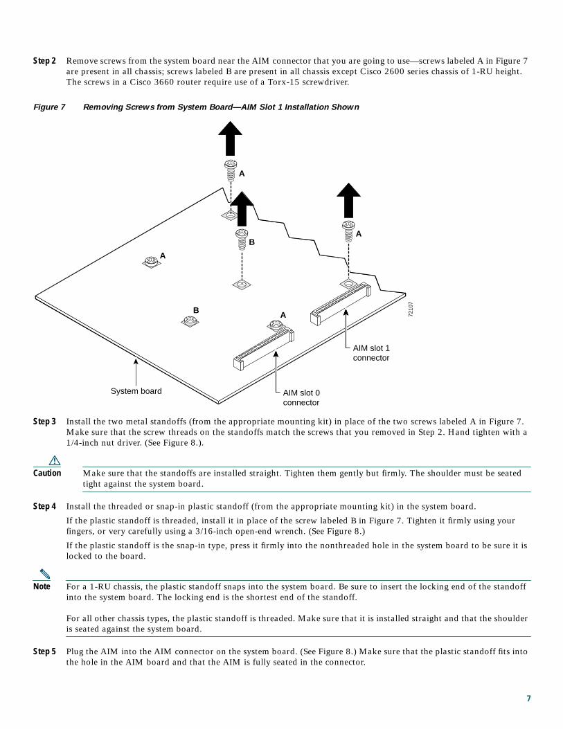
Step 2 Remove screws from the system board near the AIM connector that you are going to use—screws labeled A in Figure 7
are present in all chassis; screws labeled B are present in all chassis except Cisco 2600 series chassis of 1-RU height.
The screws in a Cisco 3660 router require use of a Torx-15 screwdriver.
Figure 7 Removing Screws from System Board—AIM Slot 1 Installation Shown
Step 3 Install the two metal standoffs (from the appropriate mounting kit) in place of the two screws labeled A in Figure 7.
Make sure that the screw threads on the standoffs match the screws that you removed in Step 2. Hand tighten with a
1/4-inch nut driver. (See Figure 8.).
Caution Make sure that the standoffs are installed straight. Tighten them gently but firmly. The shoulder must be seated
tight against the system board.
Step 4 Install the threaded or snap-in plastic standoff (from the appropriate mounting kit) in the system board.
If the plastic standoff is threaded, install it in place of the screw labeled B in Figure 7. Tighten it firmly using your
fingers, or very carefully using a 3/16-inch open-end wrench. (See Figure 8.)
If the plastic standoff is the snap-in type, press it firmly into the nonthreaded hole in the system board to be sure it is
locked to the board.
Note For a 1-RU chassis, the plastic standoff snaps into the system board. Be sure to insert the locking end of the standoff
into the system board. The locking end is the shortest end of the standoff.
For all other chassis types, the plastic standoff is threaded. Make sure that it is installed straight and that the shoulder
is seated against the system board.
Step 5 Plug the AIM into the AIM connector on the system board. (See Figure 8.) Make sure that the plastic standoff fits into
the hole in the AIM board and that the AIM is fully seated in the connector.
7210
7
AIM slot 1connector
AIM slot 0connector
System board
A
A
A
A
B
B
7
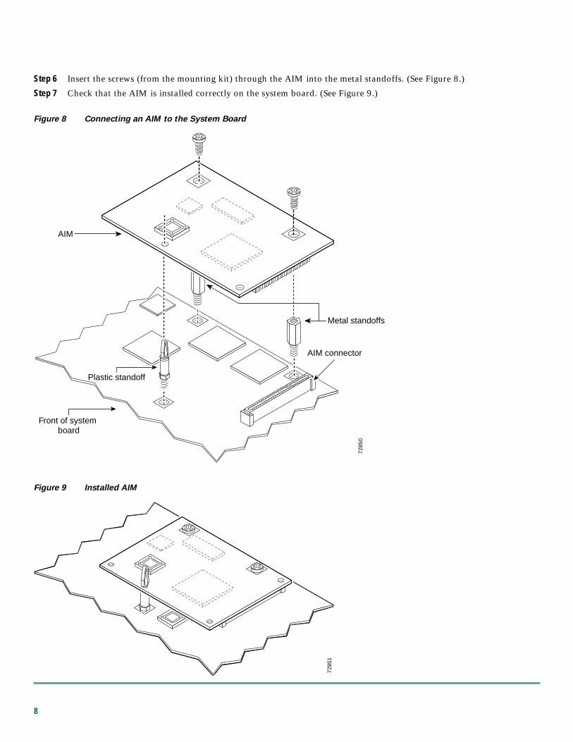
Step 6 Insert the screws (from the mounting kit) through the AIM into the metal standoffs. (See Figure 8.)
Step 7 Check that the AIM is installed correctly on the system board. (See Figure 9.)
Figure 8 Connecting an AIM to the System Board
Figure 9 Installed AIM
7285
0
Front of system board
Plastic standoff
AIM connector
Metal standoffs
AIM
7285
1
8
4 Applying the AIM Label to the ChassisThe AIM label for the chassis might be in the AIM mounting kit, or it might be attached to the label on the AIM card. Apply
the chassis label as follows:
Step 1 If the chassis label is attached to the label on the AIM card, carefully tear off the chassis label at the perforation. If the
chassis label is in the AIM mounting kit, remove the label from the kit bag.
Step 2 Peel the chassis label from its backing.
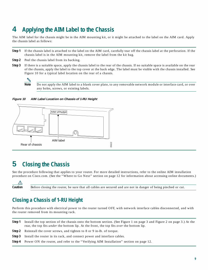
Step 3 If there is a suitable space, apply the chassis label to the rear of the chassis. If no suitable space is available on the rear
of the chassis, apply the label to the top cover at the back edge. The label must be visible with the chassis installed. See
Figure 10 for a typical label location on the rear of a chassis.
Note Do not apply the AIM label to a blank cover plate, to any removable network module or interface card, or over
any holes, screws, or existing labels.
Figure 10 AIM Label Location on Chassis of 1-RU Height
5 Closing the ChassisSee the procedure following that applies to your router. For more detailed instructions, refer to the online AIM installation
procedure on Cisco.com. (See the “Where to Go Next” section on page 12 for information about accessing online documents.)
Caution Before closing the router, be sure that all cables are secured and are not in danger of being pinched or cut.
Closing a Chassis of 1-RU HeightPerform this procedure with electrical power to the router turned OFF, with network interface cables disconnected, and with
the router removed from its mounting rack.
Step 1 Install the top section of the chassis onto the bottom section. (See Figure 1 on page 3 and Figure 2 on page 3.) At the
rear, the top fits under the bottom lip. At the front, the top fits over the bottom lip.
Step 2 Reinstall the cover screws, and tighten to 8 or 9 in-lb. of torque.
Step 3 Install the router in its rack, and connect power and interface cables.
Step 4 Power ON the router, and refer to the “Verifying AIM Installation” section on page 12.
3562
2AIM-VPN/BP
AIM labelRear of chassis
9
Closing a Chassis of 2-RU Height with Removable CoverPerform this procedure with electrical power to the router turned OFF, with network interface cables disconnected, and with
the router removed from its mounting rack.
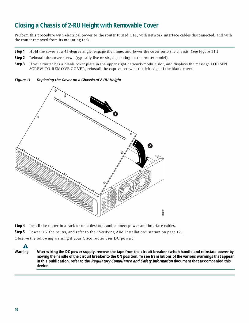
Step 1 Hold the cover at a 45-degree angle, engage the hinge, and lower the cover onto the chassis. (See Figure 11.)
Step 2 Reinstall the cover screws (typically five or six, depending on the router model).
Step 3 If your router has a blank cover plate in the upper right network-module slot, and displays the message LOOSEN
SCREW TO REMOVE COVER, reinstall the captive screw at the left edge of the blank cover.
Figure 11 Replacing the Cover on a Chassis of 2-RU Height
Step 4 Install the router in a rack or on a desktop, and connect power and interface cables.
Step 5 Power ON the router, and refer to the “Verifying AIM Installation” section on page 12.
Observe the following warning if your Cisco router uses DC power:
Warning After wiring the DC power supply, remove the tape from the circuit breaker switch handle and reinstate power bymoving the handle of the circuit breaker to the ON position. To see translations of the various warnings that appearin this publication, refer to the Regulatory Compliance and Safety Information document that accompanied thisdevice.
7285
2
1
2
10
Closing a Chassis with a Plug-In CPU/MainboardPerform this procedure with electrical power to the router turned OFF and with network interface cables disconnected.
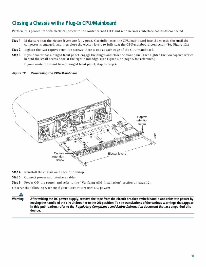
Step 1 Make sure that the ejector levers are fully open. Carefully insert the CPU/mainboard into the chassis slot until the
connector is engaged, and then close the ejector levers to fully seat the CPU/mainboard connector. (See Figure 12.)
Step 2 Tighten the two captive retention screws; there is one at each edge of the CPU/mainboard.
Step 3 If your router has a hinged front panel, engage the hinges and close the front panel; then tighten the two captive screws
behind the small access door at the right-hand edge. (See Figure 4 on page 5 for reference.)
If your router does not have a hinged front panel, skip to Step 4.
Figure 12 Reinstalling the CPU/Mainboard
Step 4 Reinstall the chassis on a rack or desktop.
Step 5 Connect power and interface cables.
Step 6 Power ON the router, and refer to the “Verifying AIM Installation” section on page 12.
Observe the following warning if your Cisco router uses DC power:
Warning After wiring the DC power supply, remove the tape from the circuit breaker switch handle and reinstate power bymoving the handle of the circuit breaker to the ON position. To see translations of the various warnings that appearin this publication, refer to the Regulatory Compliance and Safety Information document that accompanied thisdevice.
6248
9Captive
retentionscrew
Ejector levers
Captiveretention
screw
11
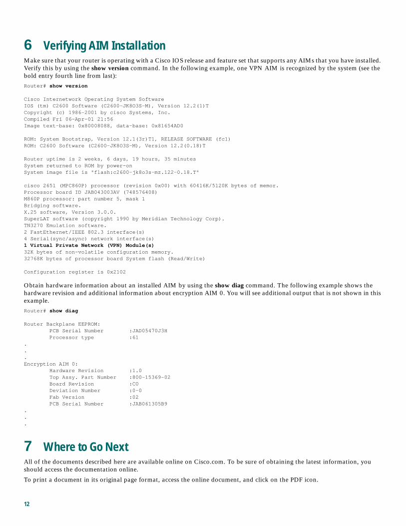
6 Verifying AIM InstallationMake sure that your router is operating with a Cisco IOS release and feature set that supports any AIMs that you have installed.
Verify this by using the show version command. In the following example, one VPN AIM is recognized by the system (see the
bold entry fourth line from last):
Router# show version
Cisco Internetwork Operating System SoftwareIOS (tm) C2600 Software (C2600-JK8O3S-M), Version 12.2(1)TCopyright (c) 1986-2001 by cisco Systems, Inc.Compiled Fri 06-Apr-01 21:56Image text-base: 0x80008088, data-base: 0x81654AD0
ROM: System Bootstrap, Version 12.1(3r)T1, RELEASE SOFTWARE (fc1)ROM: C2600 Software (C2600-JK8O3S-M), Version 12.2(0.18)T
Router uptime is 2 weeks, 6 days, 19 hours, 35 minutesSystem returned to ROM by power-onSystem image file is "flash:c2600-jk8o3s-mz.122-0.18.T"
cisco 2651 (MPC860P) processor (revision 0x00) with 60416K/5120K bytes of memor.Processor board ID JAB043003AV (748576408)M860P processor: part number 5, mask 1Bridging software.X.25 software, Version 3.0.0.SuperLAT software (copyright 1990 by Meridian Technology Corp).TN3270 Emulation software.2 FastEthernet/IEEE 802.3 interface(s)4 Serial(sync/async) network interface(s)1 Virtual Private Network (VPN) Module(s)32K bytes of non-volatile configuration memory.32768K bytes of processor board System flash (Read/Write)
Configuration register is 0x2102
Obtain hardware information about an installed AIM by using the show diag command. The following example shows the
hardware revision and additional information about encryption AIM 0. You will see additional output that is not shown in this
example.
Router# show diag
Router Backplane EEPROM: PCB Serial Number :JAD05470J3H Processor type :61...Encryption AIM 0: Hardware Revision :1.0 Top Assy. Part Number :800-15369-02 Board Revision :C0 Deviation Number :0-0 Fab Version :02 PCB Serial Number :JAB061305B9...
7 Where to Go NextAll of the documents described here are available online on Cisco.com. To be sure of obtaining the latest information, you
should access the documentation online.
To print a document in its original page format, access the online document, and click on the PDF icon.
12
To access online user documentation (PDF and HTML formats):From Cisco.com at http://www.cisco.com, under Products & Services, select Cisco 2600 Series Multiservice Platforms and select
Instructions and Guides.
For configuration information specific to Cisco 2600 series, Cisco 3600 series, and Cisco 3700 seriesrouters:Software Configuration Guide: Cisco 2600 Series, Cisco 3600 Series, and Cisco 3700 Series Routers
You can access this document at: Cisco Product Documentation > Access Servers and Access Routers > Modular Access Routers
> Cisco platform you are using > Software configuration documents for Cisco platform you are using
For detailed configuration information for specific features:Configuration Guides and Command References for the Cisco IOS software release installed on your Cisco router.
You can access these documents at: Cisco Product Documentation > Cisco IOS Software Configuration > Cisco IOS Releaseyou are using > Configuration Guides and Command References
For new features associated with a specific software release:New feature documentation for the Cisco IOS software release installed on your Cisco router.
You can access these documents at: Cisco Product Documentation > Cisco IOS Software Configuration > Cisco IOS Releaseyou are using > New Feature Documentation
For Cisco Feature Navigator:If you have an account on Cisco.com, you can get updated information about platform support for features by accessing
Cisco Feature Navigator at the following URL: http://www.cisco.com/go/fn.
For more information about AIM installation:AIM installation documents provide detailed instructions for installing specific AIMs in specific router chassis types.
You can access these documents at: Cisco Product Documentation > Access Servers and Access Routers > Modular Access
Routers > Cisco platform you are using > Hardware installation documents for Cisco platform you are using > Advanced
integration module (AIM) installation
For regulatory compliance and safety information:The regulatory compliance and safety documents provide essential safety information applicable to your router and contain
multiple-language translations of the safety warnings applicable to the Cisco routers.
You can access these documents at: Cisco Product Documentation > Access Servers and Access Routers > Modular Access
Routers > Cisco platform you are using > Regulatory compliance and safety documents for Cisco platform you are using
8 Obtaining DocumentationCisco documentation and additional literature are available on Cisco.com. Cisco also provides several ways to obtain technical
assistance and other technical resources. These sections explain how to obtain technical information from Cisco Systems.
Cisco.comYou can access the most current Cisco documentation on the World Wide Web at this URL:
http://www.cisco.com/univercd/home/home.htm
You can access the Cisco website at this URL:
http://www.cisco.com
International Cisco websites can be accessed from this URL:
http://www.cisco.com/public/countries_languages.shtml
13
Ordering DocumentationYou can find instructions for ordering documentation at this URL:
http://www.cisco.com/univercd/cc/td/doc/es_inpck/pdi.htm
You can order Cisco documentation in these ways:
• Registered Cisco.com users (Cisco direct customers) can order Cisco product documentation from the Ordering tool:
http://www.cisco.com/en/US/partner/ordering/index.shtml
• Nonregistered Cisco.com users can order documentation through a local account representative by calling Cisco Systems
Corporate Headquarters (California, USA) at 408 526-7208 or, elsewhere in North America, by calling 800 553-NETS
(6387).
9 Documentation FeedbackYou can submit e-mail comments about technical documentation to [email protected].
You can submit comments by using the response card (if present) behind the front cover of your document or by writing to the
following address:
Cisco Systems
Attn: Customer Document Ordering
170 West Tasman Drive
San Jose, CA 95134-9883
We appreciate your comments.
10 Obtaining Technical AssistanceFor all customers, partners, resellers, and distributors who hold valid Cisco service contracts, the Cisco Technical Assistance
Center (TAC) provides 24-hour-a-day, award-winning technical support services, online and over the phone. Cisco.com features
the Cisco TAC website as an online starting point for technical assistance. If you do not hold a valid Cisco service contract,
please contact your reseller.
Cisco TAC WebsiteThe Cisco TAC website provides online documents and tools for troubleshooting and resolving technical issues with Cisco
products and technologies. The Cisco TAC website is available 24 hours a day, 365 days a year. The Cisco TAC website is located
at this URL:
http://www.cisco.com/tac
Accessing all the tools on the Cisco TAC website requires a Cisco.com user ID and password. If you have a valid service contract
but do not have a login ID or password, register at this URL:
http://tools.cisco.com/RPF/register/register.do
Opening a TAC CaseUsing the online TAC Case Open Tool is the fastest way to open P3 and P4 cases. (P3 and P4 cases are those in which your
network is minimally impaired or for which you require product information.) After you describe your situation, the TAC Case
Open Tool automatically recommends resources for an immediate solution. If your issue is not resolved using the recommended
resources, your case will be assigned to a Cisco TAC engineer. The online TAC Case Open Tool is located at this URL:
http://www.cisco.com/tac/caseopen
For P1 or P2 cases (P1 and P2 cases are those in which your production network is down or severely degraded) or if you do not
have Internet access, contact Cisco TAC by telephone. Cisco TAC engineers are assigned immediately to P1 and P2 cases to help
keep your business operations running smoothly.
14
To open a case by telephone, use one of the following numbers:
Asia-Pacific: +61 2 8446 7411 (Australia: 1 800 805 227)
EMEA: +32 2 704 55 55
USA: 1 800 553-2447
For a complete listing of Cisco TAC contacts, go to this URL:
http://www.cisco.com/warp/public/687/Directory/DirTAC.shtml
TAC Case Priority DefinitionsTo ensure that all cases are reported in a standard format, Cisco has established case priority definitions.
Priority 1 (P1)—Your network is “down” or there is a critical impact to your business operations. You and Cisco will commit
all necessary resources around the clock to resolve the situation.
Priority 2 (P2)—Operation of an existing network is severely degraded, or significant aspects of your business operation are
negatively affected by inadequate performance of Cisco products. You and Cisco will commit full-time resources during normal
business hours to resolve the situation.
Priority 3 (P3)—Operational performance of your network is impaired, but most business operations remain functional. You
and Cisco will commit resources during normal business hours to restore service to satisfactory levels.
Priority 4 (P4)—You require information or assistance with Cisco product capabilities, installation, or configuration. There is
little or no effect on your business operations.
11 Obtaining Additional Publications and InformationInformation about Cisco products, technologies, and network solutions is available from various online and printed sources.
• Cisco Marketplace provides a variety of Cisco books, reference guides, and logo merchandise. Go to this URL to visit the
company store:
http://www.cisco.com/go/marketplace/
• The Cisco Product Catalog describes the networking products offered by Cisco Systems, as well as ordering and customer
support services. Access the Cisco Product Catalog at this URL:
http://cisco.com/univercd/cc/td/doc/pcat/
• Cisco Press publishes a wide range of general networking, training and certification titles. Both new and experienced users
will benefit from these publications. For current Cisco Press titles and other information, go to Cisco Press online at this
URL:
http://www.ciscopress.com
• Packet magazine is the Cisco quarterly publication that provides the latest networking trends, technology breakthroughs,
and Cisco products and solutions to help industry professionals get the most from their networking investment. Included
are networking deployment and troubleshooting tips, configuration examples, customer case studies, tutorials and training,
certification information, and links to numerous in-depth online resources. You can access Packet magazine at this URL:
http://www.cisco.com/packet
• iQ Magazine is the Cisco bimonthly publication that delivers the latest information about Internet business strategies for
executives. You can access iQ Magazine at this URL:
http://www.cisco.com/go/iqmagazine
• Internet Protocol Journal is a quarterly journal published by Cisco Systems for engineering professionals involved in
designing, developing, and operating public and private internets and intranets. You can access the Internet Protocol Journal
at this URL:
http://www.cisco.com/ipj
• Training—Cisco offers world-class networking training. Current offerings in network training are listed at this URL:
http://www.cisco.com/en/US/learning/index.html
15
Corporate HeadquartersCisco Systems, Inc.170 West Tasman DriveSan Jose, CA 95134-1706USAwww.cisco.comTel: 408 526-4000
800 553-NETS (6387)Fax: 408 526-4100
European HeadquartersCisco Systems International BVHaarlerbergparkHaarlerbergweg 13-191101 CH AmsterdamThe Netherlandswww-europe.cisco.comTel: 31 0 20 357 1000Fax: 31 0 20 357 1100
Americas HeadquartersCisco Systems, Inc.170 West Tasman DriveSan Jose, CA 95134-1706USAwww.cisco.comTel: 408 526-7660Fax: 408 527-0883
Asia Pacific HeadquartersCisco Systems, Inc.Capital Tower168 Robinson Road#22-01 to #29-01Singapore 068912www.cisco.comTel: +65 6317 7777Fax: +65 6317 7799
Cisco Systems has more than 200 offices in the following countries. Addresses, phone numbers, and fax numbers are listed on the
C i s c o W e b s i t e a t w w w . c i s c o . c o m / g o / o f f i c e s
Argentina • Australia • Austria • Belgium • Brazil • Bulgaria • Canada • Chile • China PRC • Colombia • Costa Rica • Croatia • Czech Republic • Denmark • Dubai, UAEFinland • France • Germany • Greece • Hong Kong SAR • Hungary • India • Indonesia • Ireland • Israel • Italy • Japan • Korea • Luxembourg • Malaysia • MexicoTheNetherlands • New Zealand • Norway • Peru • Philippines • Poland • Portugal • Puerto Rico • Romania • Russia • Saudi Arabia • Scotland • Singapore • SlovakiaSlovenia • South Africa • Spain • Sweden • Switzerland • Taiwan • Thailand • Turkey • Ukraine • United Kingdom • United States • Venezuela • Vietnam • Zimbabwe
Copyright © 2004 Cisco Systems, Inc. All rights reserved. CCIP, CCSP, the Cisco Arrow logo, the Cisco PoweredNetwork mark, Cisco Unity, Follow Me Browsing, FormShare, and StackWise are trademarks of
Cisco Systems, Inc.; Changing the Way We Work, Live, Play, and Learn, and iQuick Study are service marks of Cisco Systems, Inc.; and Aironet, ASIST, BPX, Catalyst, CCDA, CCDP, CCIE, CCNA, CCNP,
Cisco, the Cisco Certified Internetwork Expert logo, Cisco IOS, the Cisco IOS logo, Cisco Press, Cisco Systems, Cisco Systems Capital, the Cisco Systems logo, Empowering the Internet Generation,
Enterprise/Solver, EtherChannel, EtherSwitch, Fast Step, GigaStack, Internet Quotient, IOS, IP/TV, iQ Expertise, the iQ logo, iQ Net Readiness Scorecard, LightStream, MGX, MICA, the Networkers logo,
Networking Academy, Network Registrar, Packet, PIX, Post-Routing, Pre-Routing, RateMUX, Registrar, ScriptShare, SlideCast, SMARTnet, StrataView Plus, Stratm, SwitchProbe, TeleRouter, The Fastest Way
to Increase Your Internet Quotient, TransPath, and VCO are registered trademarks of Cisco Systems, Inc. and/or its affiliates in the United States and certain other countries.
All other trademarks mentioned in this document or Website are the property of their respective owners. The use of the word partner does not imply a partnership relationship between Cisco and any other
company. (0401R)
Printed in the USA on recycled paper containing 10% postconsumer waste.
78-14718-02
DOC-7814718=