Advanced Instrumentation for Transient Reactor...
19
Advanced Instrumentation for Transient Reactor Testing 2014 Integrated Research Project Idaho State, Kansas State, Ohio State, UW-Madison Idaho National Laboratory, CEA-Cadarache Michael Corradini, Project Lead; G.Imel, ISU, J.Roberts, KSU; T.Blue, OSU; M.Anderson, UW; K.Davis, INL, J.F.Villard, CEA May 20th, 2017
Transcript of Advanced Instrumentation for Transient Reactor...
Advanced Instrumentation for Transient Reactor Testing
2014 Integrated Research ProjectIdaho State, Kansas State, Ohio State, UW-Madison
Idaho National Laboratory, CEA-Cadarache
Michael Corradini, Project Lead; G.Imel, ISU, J.Roberts, KSU; T.Blue, OSU; M.Anderson, UW; K.Davis, INL, J.F.Villard, CEA
May 20th, 2017
IRP Project Scope
2
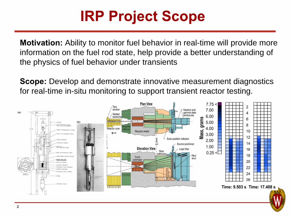
Motivation: Ability to monitor fuel behavior in real-time will provide more information on the fuel rod state, help provide a better understanding of the physics of fuel behavior under transients
Scope: Develop and demonstrate innovative measurement diagnostics for real-time in-situ monitoring to support transient reactor testing.

Advanced Instrumentation for Transient Reactor TestingM.L.Corradini, University of Wisconsin
Our team is developing specific innovative measurement diagnostics for real-time in-situ monitoring in support of transient reactor testing in three key program elements: Develop concepts that lead to next generation fuel motion monitoring system; i.e., advancements in spatial and temporal resolution for hodoscope imaging.Develop instrumentation to support in-pile transient testing that includes temperature measurements, local fast and thermal neutron flux measurements. Demonstrate these novel instrumentation measurement methods in a reactor environment using university TRIGA reactors.
Key picture or chart summarizing technology development
Technology SummaryG.Imel, ISU, J.Roberts, KSU; T.Blue, OSU; M.Corradini, M.Anderson, UW; K.Davis, INL, J.F.Villard, CEA
Key Personnel
Program: Integrated Research Project IRP-NE Budget: $3m
Key Milestones & DeliverablesTask 1 • Modeling of TREAT for hodoscope optimization
• Improve HB design w MSND design development
Task 2 • Design, fabricate, test MPFD for use in TREAT• Design, fabricate, test Diamond TC sensor• Design, fabricate, test Distributed TC sensor• Fabricate and test HTIR, Ultrasonic TCs, TC probe
Task 3 and 4
• Out-of-pile testing of these instruments in transient• In-reactor (TRIGA) testing of these instruments
Currently transient reactor testing involves hodoscopemeasurements with post-test fuel examination. This diagnostic development seeks to provide in-situ real-time monitoring of local fluxes and temperatures
Technology Impact
Provide TREAT In-situ Real-time Measurements for Transient Fuel Testing

Project Organization
4
Advanced Instrumenta on for Transient Reactor Tes ng IRP Organiza on
IRP Project Lead Michael Corradini (UW)
IRP University Partners IRP Laboratory Partners External Advisory Board
UW‐Madison Mark Anderson
Idaho State Univ. George Imel
Kansas State Univ. Jeremy Roberts Ohio State Univ:
Tom Blue/Ray Cao
Idaho Na onal Lab Kurt Davis
CEA‐Cadarache Jean‐Francois Villard
DOE/INL: S.Schuppner, D.Wachs, C.Jensen
Industry Experts: Areva, GE, NRC, NuScale,
Terrapowr,Wes nghouse
Task Areas & Inves gator Distribu ons: Task I: Real‐Time Imaging: G.Imel (ISU)***, P.Ugorowski (KSU)***, J.Roberts (KSU), T.Unruh (INL), M.Anderson (UW) Task II: Sensors: M.Anderson***, J. Blanchard, J.Ma (UW), T.Blue (OSU), D. McGregor (KSU), J.Daw (INL) Task III: Out‐of‐Pile Tests: T.Blue (OSU)***, M. Anderson (UW)***, D.Knudson (INL), B.Chase (INL) Task IV: In‐Pile Tests: D. McGregor (KSU)***, M.Anderson (UW)***, B. Agasie (UW), J.Roberts (KSU), K.Davis (INL) Task V: Transient Test Design: M.Corradini (UW)***, G.Imel (ISU), *** Indicates Team Leads or Co‐Leads
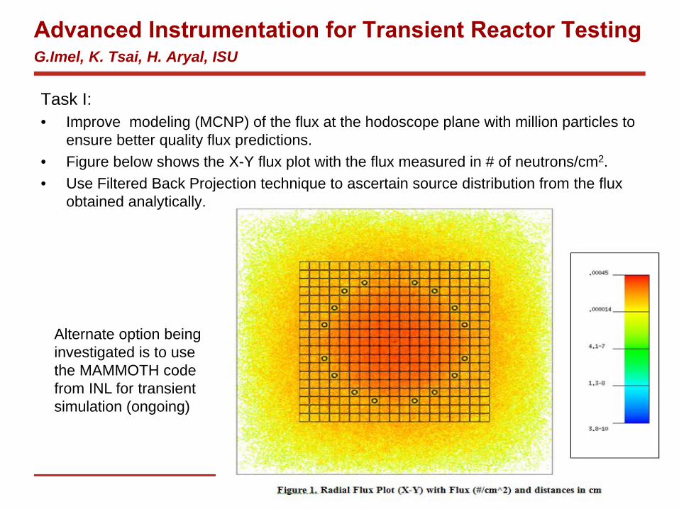
Task I:• Improve modeling (MCNP) of the flux at the hodoscope plane with million particles to
ensure better quality flux predictions. • Figure below shows the X-Y flux plot with the flux measured in # of neutrons/cm2.• Use Filtered Back Projection technique to ascertain source distribution from the flux
obtained analytically.
Advanced Instrumentation for Transient Reactor Testing G.Imel, K. Tsai, H. Aryal, ISU
Alternate option being investigated is to use the MAMMOTH code from INL for transient simulation (ongoing)

Task II:• Support fission chamber development through measurement verification of the fissile
material deposits produced at partner, KSU.• Cross-calibration measurements of KSU samples has been made with the back-to-back
(BTB) fission chamber.• Efforts are made towards reducing noise of the system for increased accuracy of
calibration measurements.• Progress made towards fabricating a smaller BTB fission chamber (OD 0.8125 in.) to
access the center of the AGN-201 reactor, which has the higher neutron flux.
Advanced Instrumentation for Transient Reactor Testing G.Imel, K. Tsai, H. Aryal, ISU
(Left) BTB cross-calibration spectrums between two KSU fissile samples. (Above) New BTB fission chamber design and current fabrication progress.

KSU highlights over project period: Development of three, unique approaches for
fast-neutron detection Hornyak evolutions with better geometry Microstructured semiconductor neutron detectors Proton-recoil gas scintillator
Design of a hodoscope mock-up for testing technologies and simulating measurements
Preliminary study of micro-pocket fission detector (MPFD) integrity with reactor pulses
Advanced Instrumentation for Transient Reactor Testing Senior Personnel: J. Roberts, J. Geuther, M. Harrison, D. McGregor, Students: J. Boyington, W. Fu, P. Ghosh; U.G. Students: M. Alshenqiti, G. Collison, E. Schlaikjer, R. Seymour
BEFORE PULSE
AFTER PULSEM.J. Harrison, M.A. Reichenberger, D.M. Nichols, D.S. McGregor, J.A. Roberts. “Preliminary Analysis of Damage to MPFDs Caused by Reactor Pulses.” Trans. Amer. Nucl. Soc. 116. (2017)
HODOSCOPE “MOCKUP” COLLIMATOR
detector sidesource side
CF4 + H2 DETECTOR
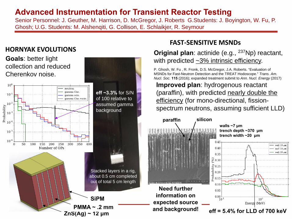
HORNYAK EVOLUTIONSFAST‐SENSITIVE MSNDs
End cap
walls ~7 μmtrench depth ~370 μmtrench width ~20 μm
paraffin silicon
eff = 5.4% for LLD of 700 keV
Original plan: actinide (e.g., 237Np) reactant, with predicted ~3% intrinsic efficiency. P. Ghosh, W. Fu , R. Fronk, D.S. McGregor, J.A. Roberts. “Evaluation of MSNDs for Fast-Neutron Detection and the TREAT Hodoscope.” Trans. Am. Nucl. Soc. 115 (2016); expanded treatment submit to Ann. Nucl. Energy (2017)
Improved plan: hydrogenous reactant (paraffin), with predicted nearly double the efficiency (for mono-directional, fission-spectrum neutrons, assuming sufficient LLD)
Need further information on
expected source and background!
Stacked layers in a rig, about 0.5 cm completed out of total 5 cm length
ZnS(Ag) ~ 12 μmPMMA ~ .2 mm
SiPM
Goals: better light collection and reduced Cherenkov noise.
eff ~3.3% for S/N of 100 relative to assumed gamma background
Advanced Instrumentation for Transient Reactor Testing Senior Personnel: J. Geuther, M. Harrison, D. McGregor, J. Roberts G.Students: J. Boyington, W. Fu, P. Ghosh; U.G. Students: M. Alshenqiti, G. Collison, E. Schlaikjer, R. Seymour

22.0000
1.0000
15.0000
4.0000
Hot Zone
Dead End
Cold Zone
1.0000
0.5625
Filled w/ HT Cement
1.0000
1.7500
SER-22-16-1/Custom Collar 1.75"OD
Fuel Rod Transient Experiment

Advanced Instrumentation for Transient ReactorT.Blue, R.Cao, B.Wilson; OSU
End cap
OSU Objectives Task IIC: Fiber Optic Temperature Sensors OSU is tasked with testing innovative fiber optic
temperature sensors for measuring temperature profiles in the TREAT testing vehicle
Key Accomplishments• Determined the radiation limits of distributed
temperature sensing in commercial silica fiber• Innovated silica fiber sensors to produce distributed
temperature measurements up to 1000 C• Mechanically ruggedized silica fiber for TREAT• Invented a new type of sapphire optical fiber that
can read out distributed temperature measurements• Modeled the time response of optical fiber sensors

Current OSU Research / Experiments• Investigating the accuracy of optical fiber sensors in a nuclear
environment (i.e. effects of gamma heating)• Developing radiation hard optical fibers and fiber sensors for long
term use in nuclear reactors• Developing a sapphire optical fiber and sensor capable of producing
distributed temperature measurements to temperatures up to 1600 C
0
10
20
30
40
50
60
70
80
90
20 20.5 21 21.5 22 22.5 23
Tem
pera
ture
(Cel
sius
)
Position along Fiber (meters)
Distributed Temperature Measurements of the CIF tube at 450 kW
Advanced Instrumentation for Transient ReactorT.Blue, R.Cao, B.Wilson; OSU
12
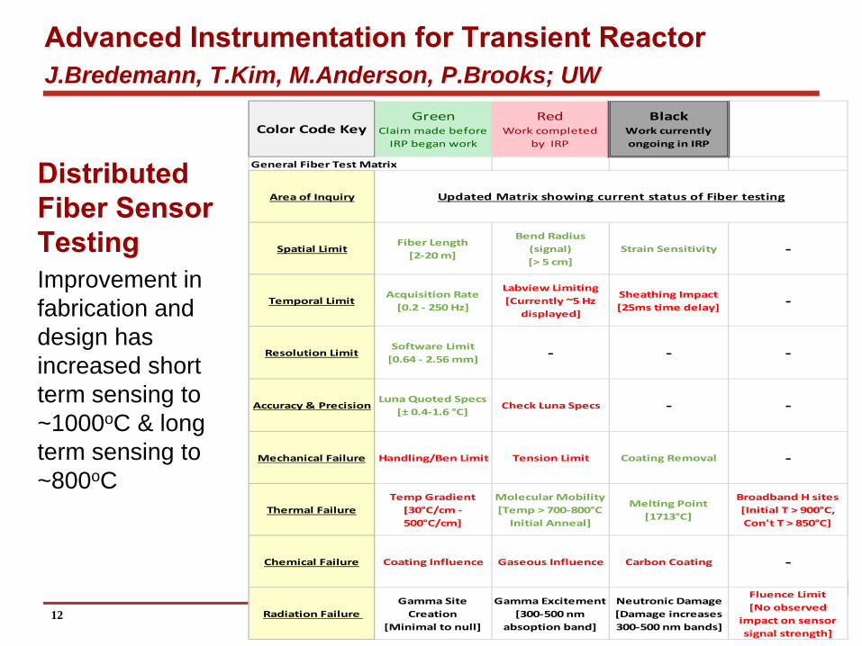
Distributed Fiber Sensor Testing Improvement in fabrication and design has increased short term sensing to ~1000oC & long term sensing to ~800oC
Advanced Instrumentation for Transient ReactorJ.Bredemann, T.Kim, M.Anderson, P.Brooks; UW
Color Code KeyGreen
Claim made beforeIRP began work
RedWork completed
by IRP
BlackWork currentlyongoing in IRP
General Fiber Test Matrix
Area of Inquiry
Spatial LimitFiber Length [2‐20 m]
Bend Radius (signal)[> 5 cm]
Strain Sensitivity ‐
Temporal LimitAcquisition Rate[0.2 ‐ 250 Hz]
Labview Limiting[Currently ~5 Hz
displayed]
Sheathing Impact[25ms time delay] ‐
Resolution LimitSoftware Limit[0.64 ‐ 2.56 mm] ‐ ‐ ‐
Accuracy & PrecisionLuna Quoted Specs
[± 0.4‐1.6 °C]Check Luna Specs ‐ ‐
Mechanical Failure Handling/Ben Limit Tension Limit Coating Removal ‐
Thermal FailureTemp Gradient[30°C/cm ‐ 500°C/cm]
Molecular Mobility[Temp > 700‐800°C Initial Anneal]
Melting Point[1713°C]
Broadband H sites[Initial T > 900°C, Con't T > 850°C]
Chemical Failure Coating Influence Gaseous Influence Carbon Coating ‐
Radiation Failure Gamma Site Creation
[Minimal to null]
Gamma Excitement[300‐500 nm
absoption band]
Neutronic Damage[Damage increases 300‐500 nm bands]
Fluence Limit[No observed
impact on sensor signal strength]
Updated Matrix showing current status of Fiber testing
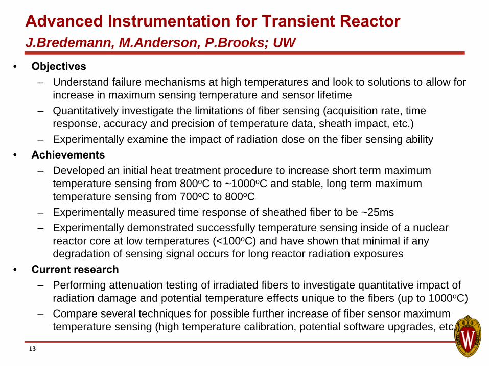
Advanced Instrumentation for Transient ReactorJ.Bredemann, M.Anderson, P.Brooks; UW
• Objectives– Understand failure mechanisms at high temperatures and look to solutions to allow for
increase in maximum sensing temperature and sensor lifetime– Quantitatively investigate the limitations of fiber sensing (acquisition rate, time
response, accuracy and precision of temperature data, sheath impact, etc.)– Experimentally examine the impact of radiation dose on the fiber sensing ability
• Achievements– Developed an initial heat treatment procedure to increase short term maximum
temperature sensing from 800oC to ~1000oC and stable, long term maximum temperature sensing from 700oC to 800oC
– Experimentally measured time response of sheathed fiber to be ~25ms– Experimentally demonstrated successfully temperature sensing inside of a nuclear
reactor core at low temperatures (<100oC) and have shown that minimal if any degradation of sensing signal occurs for long reactor radiation exposures
• Current research – Performing attenuation testing of irradiated fibers to investigate quantitative impact of
radiation damage and potential temperature effects unique to the fibers (up to 1000oC)– Compare several techniques for possible further increase of fiber sensor maximum
temperature sensing (high temperature calibration, potential software upgrades, etc.)
13

Distributed Optical Fiber Sensing Ability
14
0 10 20 30 40 50 600
200
400
600
800
1000
1200
Time [Hrs]Te
mpe
ratu
re [
o C]
Temperature profile for single point on Fiber
Fiber Optic SensorNIST Cert K-Type Thermocouple
Time [Hrs]
Pos
ition
Alo
ng F
iber
[cm
]
Temperature profile for Length of Fiber
5 10 15 20 25 30 35 40 45 50 55
120
130
140
150
160
170
180
200
400
600
800
1000
1200
Improvement in fabrication and design has increased maximum short term sensing by ~150oC and long term sensing by ~100oC
Standard Deviation:±5oC±0.66%
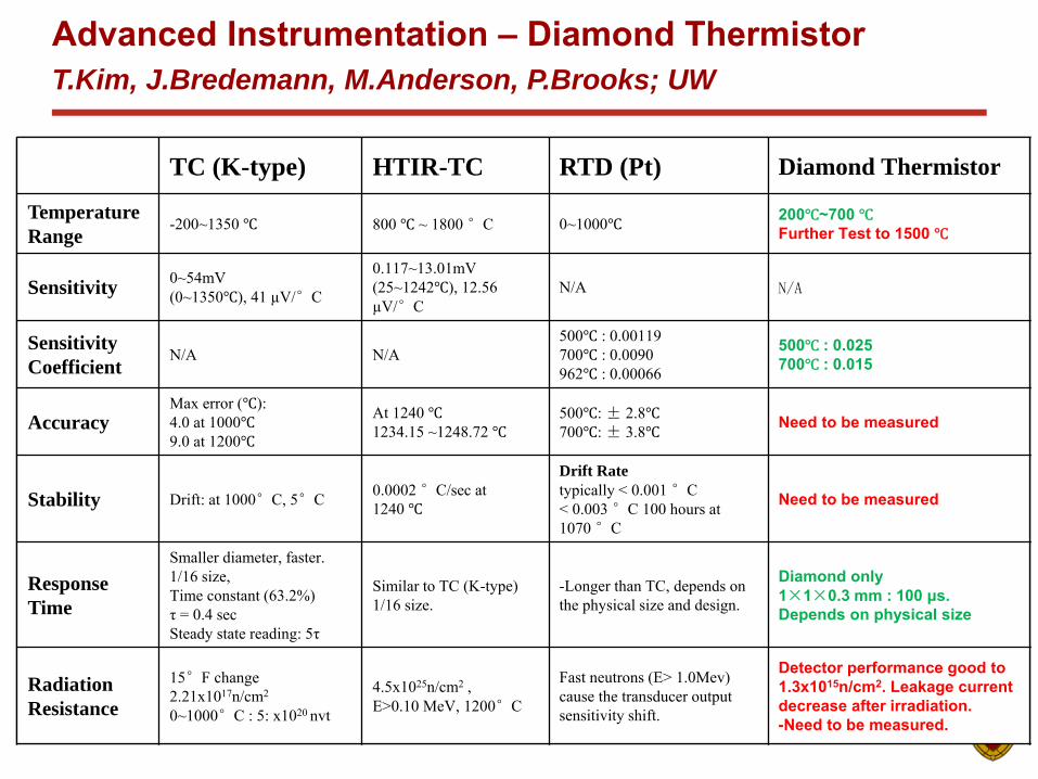
Thermal Sensor ComparisonAdvanced Instrumentation – Diamond ThermistorT.Kim, J.Bredemann, M.Anderson, P.Brooks; UW
TC (K-type) HTIR-TC RTD (Pt) Diamond Thermistor
TemperatureRange
-200~1350 800 ~ 1800 °C 0~1000 200 ~700 Further Test to 1500
Sensitivity 0~54mV(0~1350 ), 41 µV/°C
0.117~13.01mV(25~1242 ), 12.56 µV/°C
N/A N/A
SensitivityCoefficient
N/A N/A500 : 0.00119700 : 0.0090962 : 0.00066
500 : 0.025700 : 0.015
AccuracyMax error ( ): 4.0 at 10009.0 at 1200
At 1240 1234.15 ~1248.72
500 : ± 2.8700 : ± 3.8 Need to be measured
Stability Drift: at 1000°C, 5°C 0.0002 °C/sec at 1240
Drift Ratetypically < 0.001 °C< 0.003 °C 100 hours at 1070 °C
Need to be measured
ResponseTime
Smaller diameter, faster.1/16 size, Time constant (63.2%)τ = 0.4 secSteady state reading: 5τ
Similar to TC (K-type) 1/16 size.
-Longer than TC, depends on the physical size and design.
Diamond only1×1×0.3 mm : 100 μs.Depends on physical size
RadiationResistance
15°F change2.21x1017n/cm2
0~1000°C : 5: x1020 nvt
4.5x1025n/cm2 , E>0.10 MeV, 1200°C
Fast neutrons (E> 1.0Mev) cause the transducer output sensitivity shift.
Detector performance good to 1.3x10¹⁵n/cm2. Leakage current decrease after irradiation.-Need to be measured.

Diamond0.3mm
3mm
Diamond3mm
3mm
Metal PadMo + Pt
(50nm, 250nm)
Alumina tubeTC
Ni wire diameter: 0.202mm
Thermistor Operation Test (Sheath metal tube)Advanced Instrumentation – Diamond ThermistorT.Kim, J.Bredemann, M.Anderson, P.Brooks; UW
InsulatorDiamond
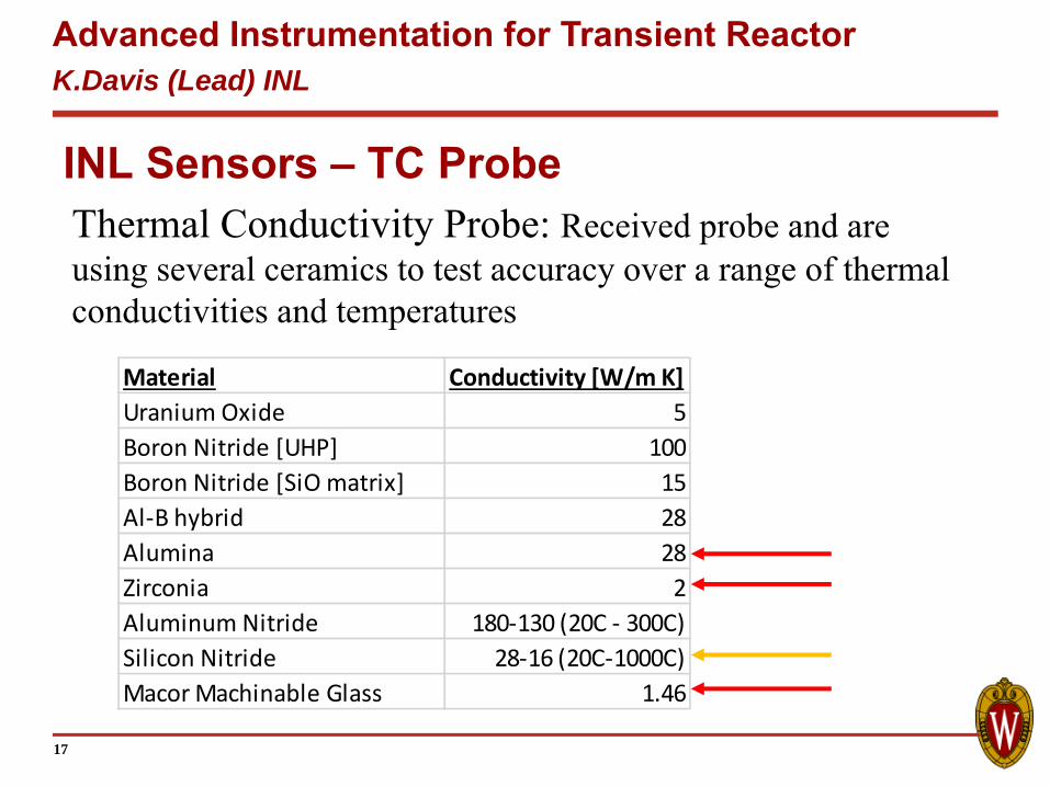
INL Sensors – TC ProbeThermal Conductivity Probe: Received probe and are using several ceramics to test accuracy over a range of thermal conductivities and temperatures
17
Material Conductivity [W/m K]Uranium Oxide 5Boron Nitride [UHP] 100Boron Nitride [SiO matrix] 15Al‐B hybrid 28Alumina 28Zirconia 2Aluminum Nitride 180‐130 (20C ‐ 300C)Silicon Nitride 28‐16 (20C‐1000C)Macor Machinable Glass 1.46
Advanced Instrumentation for Transient ReactorK.Davis (Lead) INL
INL Sensors
• HTIR sensor is under test at UW out-of-pile• INL Ultrasonic TC fabricated (three probes)
– Inconel with 1 sensing region– Inconel with 5 sensing regions– Moly with 1 sensing region
• All were shipped to UW and testing underway• Cross-comparison with other sensors
18
Advanced Instrumentation for Transient ReactorK.Davis (Lead) INL
Task III and Task IV: Integral Testing
19
Task III: Out-of-pile testing has begun with selected sensors (ongoing spring and summer)• MSND and MPFD results at KSU • HTIR and Fiber optic results at OSU and UW• Diamond-diode at UW • Combined TC sensors in test canisterTask IV: Safety case is developed to present to Reactor Safety committee for review and approval (summer)In-pile testing with HTIR, Fiber-Sensor, Ultrasonic Thermometry, and Diamond Thermistor (summer - fall)