


International Journal of I.C. Engines and Gas Turbines vol 2 issue 1
Upload
manojdhanbadCategory
view
127download
0description
2013
G.PRANESH B.E (MECHANICAL ENGINEERING)
4/23/2013
ADVANCED I.C ENGINES
G.PRANESH B.E (Mechanical)
e.mail:[email protected] 1 visit:www.pranesh.freeblog.biz
ME2041 ADVANCED I.C. ENGINES L T P C 3 0 0 3 OBJECTIVES:
To update the knowledge in engine exhaust emission control and alternate fuels
To enable the students to understand the recent developments in IC Engines UNIT I SPARK IGNITION ENGINES 9 Air-fuel ratio requirements, Design of carburetor ”fuel jet size and venture size, Stages of combustion-normal and abnormal combustion, Factors affecting knock, Combustion chambers, Introduction to thermodynamic analysis of SI Engine combustion process. UNIT II COMPRESSION IGNITION ENGINES 9 Stages of combustion-normal and abnormal combustion ” Factors affecting knock, Direct and Indirect injection systems, Combustion chambers, Turbo charging, Introduction to Thermodynamic Analysis of CI Engine Combustion process. UNIT III ENGINE EXHAUST EMISSION CONTROL 9 Formation of NOX, HC/CO mechanism, Smoke and Particulate emissions, Green House Effect, Methods of controlling emissions, Three way catalytic converter and Particulate Trap, Emission (HC, CO, NO and NOX,) measuring equipment’s, Smoke and Particulate measurement, Indian Driving Cycles and emission norms UNIT IV ALTERNATE FUELS 9 Alcohols , Vegetable oils and bio-diesel, Bio-gas, Natural Gas , Liquefied Petroleum Gas ,Hydrogen , Properties , Suitability, Engine Modifications, Performance , Combustion and Emission Characteristics of SI and CI Engines using these alternate fuels. UNIT V RECENT TRENDS 9 Homogeneous Charge Compression Ignition Engine, Lean Burn Engine, Stratified Charge Engine, Surface Ignition Engine, Four Valve and Overhead cam Engines, Electronic Engine Management, Common Rail Direct Injection Diesel Engine, Gasoline Direct Injection Engine, Data Acquisition System ”pressure pick up, charge amplifier PC for Combustion and Heat release analysis in Engines.

G.PRANESH B.E (Mechanical)
e.mail:[email protected] 2 visit:www.pranesh.freeblog.biz
ME2041 ADVANCED I.C. ENGINES
UNIT I SPARK IGNITION ENGINES
2 MARK QUESTION AND ANSWER
1. What are the stages of combustion in a SI engines?
The stages of combustion in a SI engines are: FIRST STAGE: Ignition lag (or) preparation phase SECOND STAGE: propagation of flame THIRD STAGE: After burning
2. What are the various factors that affect the flame speed?
a) Turbulence b) F/A ratio c) T, P d) Compression ratio e) Engine speed, size &output
3. Define normal combustion?
In normal combustion, the flame initiated by the spark travels across the combustion chamber in a fairly uniform manner.
4. Define abnormal combustion and its consequences?
Under certain operating conditions the combustion deviates from its normal Course leading to loss of performance and possible damage to the engine are termed as abnormal combustion (or) knocking combustion. Consequences are (1).Loss of power (2). Recurring preignition (3). Mechanical damage to the engine
5. What is equivalence ratio?
The ratio of the actual fuel-air ratio to the stoichiometric fuel ” air ratio.
6. Short note on SI engine equivalence ratio requirements?
In a homogeneous mixture with equivalence ratio close to 1.0 the flame speed is normally of the order of 40cm/s .However in a SI engine the maximum flame speed is obtained when
Φ is between 1.1 and 1.2 (i.e.) when the mixture is slightly richer than stoichiometric.
G.PRANESH B.E (Mechanical)
e.mail:[email protected] 3 visit:www.pranesh.freeblog.biz
7. Explain the type of vibration produced when auto ignition occurs.
Two different vibrations are produced. 1. In one case, a large amount of mixture may auto ignite giving use to a very rapid increase in pressure throughout the chamber and there will be a direct blow on free vibration of the engine parts
2. In another case, larger pressure differences may exit in the combustion chamber and the resulting gas vibration can force the walls of the chamber to vibrate at the same frequency as the gas.
8. What is the method to detect the phenomenon of knocking?
The scientific method to detect the phenomenon of knocking is to use a pressure transfer this transducer is connected, usually to a cathode ray oscilloscope. Thus pressure-time traces can be obtained from the pressure transducer.
9. List out some of the knock limited parameters?
The knock limited parameters are: 1. Knock limited compression ratio2. Knock limited into pressure3. Knock limited Indicated mean effective pressure. (Klimep)
10. Define performance number?
Performance number is defined as the ratio. Of Knock limited Indicated mean effective pressure with the sample fuel to knock limited Indicated mean effective pressure with ISO-OCTANE .when the inlet pressure is kept constant.
11. List the factors that are involved in either producing (or) preventing knock.
The factors that are involved in either producing (or) preventing knock are temperature, pressure, density of the unburned charge and the time factor.
12. List the parameters which are affecting knock in SI engine?
The parameters which are directly (or) indirectly connected with knocking are inlet temperature of mixture compression ratio, mass of inducted charge, power output of the engine.
13. List the parameters in time factors that reduce the knocking?
Parameters are turbulence, engine speed, flame travel distance, combustion chamber shape and location of spark plug.
G.PRANESH B.E (Mechanical)
e.mail:[email protected] 4 visit:www.pranesh.freeblog.biz
14. List the composition factors in the knocking?
Air ” fuel ratio and octane value of the fuel are the composition factors.
15. Write the different types of combustion chambering SI engine?
T-Head type, L- Head type, I- Head type, F- Head type.
16. List the drawbacks of the carburetion?
1. Non uniform distribution of mixture in multi cylinder engines.2. Loss of volumetric efficiency due to retraction for mixture flow and possibility of back firing.
17. List some of the important requirements of automobile carburettors?
1. Ease of starting the engine, particularly under low ambient conditions.2. Good and quick acceleration of the engine.3. Good fuel economy.4. Ensuring full torque at low speeds.
18. What are the general types of carburetors?
Types are UPDRAUGHT, DOWN DRAUGHT, and CROSS DRAUGHT.
19. What are the essential parts, compensating device and additional system (modern) carburetors?
Parts ” fuel strainer, float chamber, main metering and idling system, the choke& the throttle. Compensating devise- Air ” bleed jet, compensating jet, Emulsion tube, auxiliary valve and port, back suction control mechanism. Additional system” Ant dieseling, richer coasting, acceleration pump and economic (or) power enrichment system.
20. Define carburetion?
The process of formation of a combustible fuel” air mixture by mixing the proper amount of fuel with air before admission to engine cylinder is called carburetion.
21. What are the factors effecting carburetion?
1. The engine speed 2. The vaporization characteristics of fuel 3. The temperature of the incoming air 4. The design of the carburettor
G.PRANESH B.E (Mechanical)
e.mail:[email protected] 5 visit:www.pranesh.freeblog.biz
16 MARK QUESTION AND ANSWER
Air-fuel ratio requirements of SI Engine
As per requirement of engine, the carburetor provides an air-fuel ratio, which must be within combustion range. Engine is cold at the time of starting so, very rich mixture is required. Rich mixture is also required at time of idling and producing maximum power. During the normal running, a comparatively lean mixture can be used. For petrol engine; different air-fuel ratios are required under various conditions of load. These are as discussed below.
i) Air-Fuel Ratio for Starting
Very rich mixture (10: 1) is required at starting of engine. During starting very small amount of fuel is vaporizes and rest of it stay in the liquid state so as to give an ignitable mixture.
ii) Air-Fuel Ratio for Idling
An idling, engine demands a rich mixture, which can be made leaner as the throttle is gradually opened. During idling, the pressure in the inlet manifold is about 20 to 25% of atmospheric pressure. At suction stroke, inlet valve opens and the product of combustion trapped in the clearance volume, expands in the inlet manifold. Latter when the piston moves downwards, the gases along with the fresh charges go into the cylinder. A rich mixture must be supplied during idling, to counteract the tendency of dilution and to get an ignitable mixture.
iii) Air-Fuel Ratio for Medium Load
Most of the time, engine is running in medium load condition, therefore, it is desirable that the running should be most economical in this condition. So a lean mixture can be supplied, as engine has low fuel consumption at medium load. For multi cylinder engine, slightly more fuel is required due to mal distribution of fuel.
iv) Air-Fuel Ratio for Maximum Power Range
When maximum power is required, the engine must be supplied with rich mixture as the economy is of no consideration. As the engine enters in the power range, the spark must be retarded otherwise knocking would occur. A lean mixture burns at latter part of working stroke. As the exhaust valve expose to high temperature
G.PRANESH B.E (Mechanical)
e.mail:[email protected] 6 visit:www.pranesh.freeblog.biz
gases and have very less time to cool down. Moreover, the excess air in the lean mixture may cause an oxidizing action on the hot exhaust valve and leads to failure.
v) Air-Fuel Ratio for Acceleration
Even during normal running, sometimes more power is required for a short period such as to accelerate the vehicle for overtaking etc. During this period rich mixture is required.
Stages of combustion process in SI Engine with P- diagram
Three Stage of Combustion
There are three stages of combustion in SI Engine as shown
i. Ignition lag stage
ii. Flame propagation stage
iii. After burning stage
i. Ignition lag stage:
There is a certain time interval between instant of spark and instant where there is a noticeable rise in pressure due to combustion. This time lag is called IGNITION LAG. Ignition lag is the time interval in the process of chemical reaction during which molecules get heated up to self-ignition temperature , get ignited and produce a self-propagating nucleus of flame. The ignition lag is generally expressed in terms of crank angle (q1). The period of ignition lag is shown by path ab. Ignition lag is very small and lies between 0.00015 to 0.0002 seconds. An ignition lag of0.002 seconds corresponds to 35 deg crank rotation when the engine is running at 3000 RPM. Angle of advance increase with the speed. This is a chemical process depending upon the nature of fuel, temperature and pressure, proportions of exhaust gas and rate of oxidation or burning.

G.PRANESH B.E (Mechanical)
e.mail:[email protected] 7 visit:www.pranesh.freeblog.biz
ii. Flame propagation stage:
Once the flame is formed at ‚b‛, it should be self-sustained and must be able to propagate through the mixture. This is possible when the rate of heat generation by burning is greater than heat lost by flame to surrounding. After the point ‚b‛, the flame propagation is abnormally low at the beginning as heat lost is more than heat generated. Therefore pressure rise is also slow as mass of mixture burned is small. Therefore it is necessary to provide angle of advance 30 to35 deg, if the peak pressure to be attained 5-10 deg after TDC. The time required for crank to rotate through an angle q2 is known as combustion period during which propagation of flame takes place.
iii. After burning:
Combustion will not stop at point ‚c‛ but continue after attaining peak pressure and this combustion is known as after burning. This generally happens when the rich mixture is supplied to engine.
G.PRANESH B.E (Mechanical)
e.mail:[email protected] 8 visit:www.pranesh.freeblog.biz
Factors affecting knocking in SI engines
The various engine variables affecting knocking can be classified as:
“ Temperature factors “ Density factors “ Time factors “ Composition factors
(A) TEMPERATURE FACTORS
Increasing the temperature of the unburned mixture increase the possibility of knock in the SI engine we shall now discuss the effect of following engine parameters on the temperature of the unburned mixture:
i. Raising the Compression Ratio
Increasing the compression ratio increases both the temperature and pressure (density of the unburned mixture). Increase in temperature reduces the delay period of the end gas which in turn increases the tendency to knock.
ii.Supercharging
It also increases both temperature and density, which increase the knocking tendency of engine
iii.Coolant Temperature
Delay period decreases with increase of coolant temperature, decreased delay period increase the tendency to knock
iv.Temperature Of The Cylinder And Combustion Chamber Walls :
The temperature of the end gas depends on the design of combustion chamber. Sparking plug and exhaust valve are two hottest parts in the combustion chamber and uneven temperature leads to pre-ignition and hence the knocking.

G.PRANESH B.E (Mechanical)
e.mail:[email protected] 9 visit:www.pranesh.freeblog.biz
(B) DENSITY FACTORS
Increasing the density of unburnt mixture will increase the possibility of knock in the engine. The engine parameters which affect the density are as follows:
“ Increased compression ratio increase the density “ Increasing the load opens the throttle valve more and thus the density “ Supercharging increase the density of the mixture “ Increasing the inlet pressure increases the overall pressure during the cycle.
The high pressure end gas decreases the delay period which increase the tendency of knocking.
“ Advanced spark timing: quantity of fuel burnt per cycle before and after TDC position depends on spark timing. The temperature of charge increases by increasing the spark advance and it increases with rate of burning and does not allow sufficient time to the end mixture to dissipate the heat and increase the knocking tendency
(C) TIME FACTORS
Increasing the time of exposure of the unburned mixture to auto-ignition conditions increase the possibility of knock in SI engines.
i. Flame travel distance:
If the distance of flame travel is more, then possibility of knocking is also more. This problem can be solved by combustion chamber design, spark plug location and engine size. Compact combustion chamber will have better anti-knock characteristics, since the flame travel and combustion time will be shorter. Further, if the combustion chamber is highly turbulent, the combustion rate is high and consequently combustion time is further reduced; this further reduces the tendency to knock.
ii.Location of sparkplug:
A spark plug which is centrally located in the combustion chamber has minimum tendency to knock as the flame travel is minimum. The flame travel can be reduced by using two or more spark plugs.
G.PRANESH B.E (Mechanical)
e.mail:[email protected] 10 visit:www.pranesh.freeblog.biz
iii.Location of exhaust valve:
The exhaust valve should be located close to the spark plug so that it is not in the end gas region; otherwise there will be a tendency to knock.
iv.Engine size
Large engines have a greater knocking tendency because flame requires a longer time to travel across the combustion chamber. In SI engine therefore, generally limited to 100mm
v.Turbulence of mixture
Decreasing the turbulence of the mixture decreases the flame speed and hence increases the tendency to knock. Turbulence depends on the design of combustion chamber and one engine speed.
COMPOSITION FACTORS
i. Molecular Structure
The knocking tendency is markedly affected by the type of the fuel used. Petroleum fuels usually consist of many hydro-carbons of different molecular structure. The structure of the fuel molecule has enormous effect on knocking tendency. Increasing the carbon-chain increases the knocking tendency and centralizing the carbon atoms decreases the knocking tendency. Unsaturated hydrocarbons have less knocking tendency than saturated hydrocarbons.
ii.Fuel-air ratio:
The most important effect of fuel-aft ratio is on the reaction time or ignition delay. When the mixture is nearly 10% richer than stoichiometric (fuel-air ratio =0.08) ignition lag of the end gas is minimum and the velocity of flame propagation is maximum. By making the mixture leaner or richer (than F/A 0.08) the tendency to knocks decreased. A too rich mixture is especially effective in decreasing or eliminating the knock due to longer delay and lower temperature of compression.
iii.Humidity of air:
Increasing atmospheric humidity decreases the tendency to knock by decreasing the reaction time of the fuel

G.PRANESH B.E (Mechanical)
e.mail:[email protected] 11 visit:www.pranesh.freeblog.biz
DIFFERENT TYPES OF COMBUSTION CHAMBERS IN SI ENGINE
Variations are enumerated and discussed below:
T-head combustion chamber L-head combustion chamber I-head (or overhead valve) combustion chamber F-head combustion chamber
It may be noted that these chambers are designed to obtain the objectives namely:
A high combustion rate at the start. A high surface-to-volume ratio near the end of burning. A rather centrally located spark plug.
i.T Head Type Combustion chambers
This was first introduced by Ford Motor Corporation in 1908. This design has following disadvantages.
Requires two cam shafts (for actuating the in-let valve and exhaust valve separately) by two cams mounted on the two cam shafts.
Very prone to detonation. There was violent detonation even at a compression ratio of 4. This is because the average octane number in 1908 was about 40 -50.
ii.L Head Type Combustion chambers
It is a modification of the T-head type of combustion chamber. It provides the two values on the same side of the cylinder, and the valves are operated through tappet by a single camshaft. This was first introduced by Ford motor in 1910-30 and was quite popular for some time. This design has an advantage both from manufacturing and maintenance point of view.
Advantages:
Valve mechanism is simple and easy to lubricate. Detachable head easy to remove for cleaning and decarburizing without Disturbing either the valve gear or main pipe work. Valves of larger sizes can be provided.

G.PRANESH B.E (Mechanical)
e.mail:[email protected] 12 visit:www.pranesh.freeblog.biz
Disadvantages:
Lack of turbulence as the air had to take two right angle turns to enter the cylinder and in doing so much initial velocity is lost.
Extremely prone to detonation due to large flame length and slow combustion due to lack of turbulence.
More surface-to-volume ratio and therefore more heat loss. Extremely sensitive to ignition timing due to slow combustion process Valve size restricted. Thermal failure in cylinder block also. In I-head engine the thermal failure is
confined to cylinder head only.
iii.Overhead valve or I head combustion chamber
The disappearance of the side valve or L-head design was inevitable at high compression ratio of 8:1 because of the lack of space in the combustion chamber to accommodate the valves. Diesel engines, with high compression ratios, invariably used overhead valve design. Since 1950 or so mostly overhead valve combustion chambers are used. This type of combustion chamber has both the inlet valve and the exhaust valve located in the cylinder head. An overhead engine is superior to side valve engine at high compression ratios.
The overhead valve engine is superior to side valve or L head engine at high compression ratios, for the following reasons:
Lower pumping losses and higher volumetric efficiency from better breathing of the engine from larger valves or valve lifts and more direct passageways.
Less distance for the flame to travel and therefore greater freedom from knock, or in other words, lower octane requirements.
Less force on the head bolts and therefore less possibility of leakage (of compression gases or jacket water). The projected area of a side valve combustion chamber is inevitably greater than that of an overhead valve chamber.
Removal of the hot exhaust valve from the block to the head, thus confining heat failures to the head. Absence of exhaust valve from block also results in more uniform cooling of cylinder and piston.
Lower surface-volume ratio and, therefore, less heat loss and less air pollution.

G.PRANESH B.E (Mechanical)
e.mail:[email protected] 13 visit:www.pranesh.freeblog.biz
F- Head combustion chamber
In such a combustion chamber one valve is in head and other in the block. This design is a compromise between L-head and I-head combustion chambers. One of the most F head engines (wedge type) is the one used by the Rover Company for several years. Another successful design of this type of chamber is that used in Willeys jeeps.
Advantages
High volumetric efficiency Maximum compression ratio for fuel of given octane rating High thermal efficiency It can operate on leaner air-fuel ratios without misfiring.
The drawback
This design is the complex mechanism for operation of valves and expensive special shaped piston.

G.PRANESH B.E (Mechanical)
e.mail:[email protected] 14 visit:www.pranesh.freeblog.biz
Combustion
Normal combustion
Spark-ignited flame moves steadily across the combustion chamber until the charge is fully consumed. A combustion process which is initiated solely by a timed spark and in which the flame front moves completely across the combustion chamber in a uniform manner at a normal velocity
Abnormal combustion
Fuel composition, engine design and operating parameters, combustion chamber deposits may prevent occurring of the normal combustion process. A combustion process in which a flame front may be started by hot combustion-chamber surfaces either prior to or after spark ignition, or a process in which some part or all of the charge may be consumed at extremely high rates
There are two types of abnormal combustion:
Knock Surface ignition
i.Knock
Knock is the auto ignition of the portion of fuel, air and residual gas mixture ahead of the advancing flame that produces a noise. As the flame propagates across combustion chamber, end gas is compressed causing pressure, temperature and density to increase. This causes high frequency pressure oscillations inside the cylinder that produce sharp metallic noise called knock. Knock will not occur when the flame front consumes the end gas before these reactions have time to cause fuel-air mixture to autoignite. Knock will occur if the precombustion reactions produce auto ignition before the flame front arrives
ii.Surface Ignition
Surface ignition is ignition of the fuel-air charge by overheated valves or spark plugs, by glowing combustion chamber deposits or by any other hot spot in the engine combustion chamber - it is ignition by any source other than the spark plug. It may occur before the spark plug ignites the charge (preignition) or after normal ignition (postignition).

G.PRANESH B.E (Mechanical)
e.mail:[email protected] 15 visit:www.pranesh.freeblog.biz
Carburetor (Same Venturi and Fuel jet operation)
A device used in petrol engines for atomizing the petrol, controlling its mixture with air, and regulating the intake of the air-petrol mixture into the engine.
The carburetor has several functions: 1) it combines gasoline and air creating a highly combustible mixture, 2) it regulates the ratio of air and fuel, and 3) it controls the engine's speed
The function of the carburetor is to supply the proper fuel-air ratio to the engine cylinder during suction created by the downward movement of the piston. As the piston moves downward a pressure difference is created between the atmosphere and the cylinder which leads to the suction of air in the cylinder. This sucked air will also carry with it some droplets of fuel discharged from a tube. The tube has an orifice called carburetor jet which is open to the path of sucked air. The rate at which fuel is discharged into the air will depend upon the pressure difference created. To ensure the atomization of fuel the suction effect must be strong and the fuel outlet should be small.
Working of Simple Carburetor:
To increase the suction effect the passage of air is made narrow. It is made in the form of venturi. The opening of the fuel jet is placed at the venturi where the suction is greatest because the velocity of air will be maximum at that point.
The fig. shows a simple carburetor consists of float chamber, nozzle, a venturi, a choke valve and a throttle valve. The narrow passage is called venturi. The opening of the fuel is normally placed a little below the venturi section.
The atomized fuel and air is mixed at this place and then supplied to the intake manifold of the cylinder. The fuel is supplied to the fuel jet from the float chamber and the supply of the fuel to the float chamber is regulated by the float pivot and supply valve. As the fuel level in the chamber decreases the float pivot will open the supply of the fuel from fuel tank.

G.PRANESH B.E (Mechanical)
e.mail:[email protected] 16 visit:www.pranesh.freeblog.biz
As the air velocity of air passes through the venturi section will be maximum correspondingly the pressure will be minimum. Due to the pressure difference between the float chamber and the throat of the venturi, fuel is discharged from the jet to the air. To prevent the overflow of fuel from the jet, the level of fuel in the chamber is kept at a level slightly below the tip.
The quantity of the fuel supplied is governed by the opening of the butterfly valve situated after the venturi tube. As the opening of the valve is small, a less quantity of fuel-air mixture is supplied to the cylinder which results in reduced power output. If the opening of the valve is more than an increased quantity of fuel is supplied to the cylinder which results in greater output.
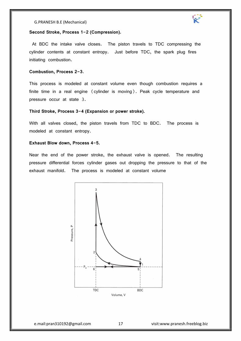
Introduction to thermodynamic analysis of SI Engine combustion process
First stroke, Process 6-1 (Induction).
The piston travels from TDC to BDC with the intake valve open and the exhaust valve closed (some valve overlap occurs near the ends of strokes to accommodate the finite time required for valve operation). The temperature of the incoming air is increased 25-35 over the surrounding air as the air passes through the hot intake manifold.
G.PRANESH B.E (Mechanical)
e.mail:[email protected] 17 visit:www.pranesh.freeblog.biz
Second Stroke, Process 1-2 (Compression).
At BDC the intake valve closes. The piston travels to TDC compressing the cylinder contents at constant entropy. Just before TDC, the spark plug fires initiating combustion.
Combustion, Process 2-3.
This process is modeled at constant volume even though combustion requires a finite time in a real engine (cylinder is moving). Peak cycle temperature and pressure occur at state 3.
Third Stroke, Process 3-4 (Expansion or power stroke).
With all valves closed, the piston travels from TDC to BDC. The process is modeled at constant entropy.
Exhaust Blow down, Process 4-5.
Near the end of the power stroke, the exhaust valve is opened. The resulting pressure differential forces cylinder gases out dropping the pressure to that of the exhaust manifold. The process is modeled at constant volume

G.PRANESH B.E (Mechanical)
e.mail:[email protected] 18 visit:www.pranesh.freeblog.biz
Fourth Stroke, Process 5-6.
With the exhaust valve open, the piston travels from BDC to TDC expelling most of the remaining exhaust gases.
Thermodynamic Analysis
Process 6-1. 6 1 0 1 6w P v v
Process 1-2. 1 2 1 2w u u 1 2 0q
Process 2-3. 2 3 0w 2 3 3 2inq q u u 2 3 in f LHV cQ Q m Q
Where: LHVQ lower heating value of the fuel
c Combustion efficiency - the fraction of fuel actually burned. Its usual range is 0.95-0.98.
3 21LHV cQ AF u u AF = air/fuel ratio
Note: This expression assumes that the cylinder contents are air (e.g. 15 lb of air plus one lb of fuel per lb of fuel).
Process 3-4. 3 4 0q 3 4 3 4w u u
Process 4-5. 4 5 5 4q u u
Process 5-6. 5 6 0 6 5w P v v
Thermal efficiency. 1net out
t
in in
w q
q q
,
net i j
i j i j
w w
in outq q

G.PRANESH B.E (Mechanical)
e.mail:[email protected] 19 visit:www.pranesh.freeblog.biz
UNIT II COMPRESSION IGNITION ENGINES
2 MARK QUESTION AND ANSWER
1. What are the stages of combustion in C.I engine?
The stages of combustion in C.I engine are four stages:
Stage I: ignition delay period (preparatory phase) Stage 2: Period of rapid combustion. Stage 3: Period of controlled combustion. Stage 4: Period of after burning.
2. What is ignition delay period?
The fuel does not ignite immediately upon injection into the combustion chamber. There is a definite period of inactivity between the time when the first droplet of fuel hits the hot air in the combustion chamber and the time it starts through the actual burning phase. This period is known as ignition delay period.
3. What are two delays occur in ignition delay period?
The two delays occur in ignition delay period are the physically delay and chemically delay. Physical delay is the time between the beginning of injection and the attainment of chemical reaction conditions. Chemical delay is the reaction starts slowly and then accelerates until the inflammation or ignition takes place.
4. List the factors affecting the delay period?
The factors affecting the delay period are:
1. Compression ratio. 2. Atomization of the fuel.
3. Quality of the fuel. 4. Intake temperature and pressure.
5. Explain the effect of quality of fuel factor on the delay period?
Self-ignition temperature is the most important property of the fuel which affects the delay period. A lower self-ignition temperature and fuel with higher cetane number give lower delay period and smooth engine operation. Other properties of the fuel which affects the delay period are latent heat, viscosity and surface tension.
G.PRANESH B.E (Mechanical)
e.mail:[email protected] 20 visit:www.pranesh.freeblog.biz
6. Write the classification of combustion chamber in C.I engine?
Combustion chamber in C.I engine is classified into two categories:
1. Direct-injection type 2. Indirect-injection type
7. What are the types of open combustion chamber?
In open combustion chamber there are many designs some are
a. Shallow depth chamber b. hemispherical chamber
c. Cylindrical chamber d. Toroidal chamber
8. What are the advantages and disadvantages of open combustion chamber type?
Advantages:
Minimum heat loss during compression because of lower surface area to volume ratio
No cold starting problems Fine atomization because of multihole nozzle
Disadvantages:
High fuel injection pressure required and hence complex design of fuel injection pump
Necessity of accurate metering of fuel by the injection system, particularly for small engines.
9. What is indirect injection type of combustion?
Indirect injection type of combustion chamber in which the combustion space is divided in to two or more distinct compartment connected by restricts passages. This creates considerable pressure difference between them during the combustion process.
10. Write the classification of indirect injection chamber (divided combustion chamber)
Swirl chamber ” in which compression swirl is generation. Precombustion chamber ” in which combustion swirl is induced. Air cell chamber ” in which both compression and combustion swirl are
induced.

G.PRANESH B.E (Mechanical)
e.mail:[email protected] 21 visit:www.pranesh.freeblog.biz
11. What are the applications of swirl chamber?
Swirl chamber type finds application
Where fuel quality is difficult to control Where reliability under adverse condition is more important than fuel economy Use of single hole of larger diameter for the fuel spray nozzle is often
important consideration for the choice of fluid chamber engine.
12. List the advantages and drawbacks of indirect injection chamber:
Advantages:
Injection pressure required is low Direction of spraying is not very important
Disadvantages:
Poor cold starting performance required heater plugs Specific fuel consumption is high
13. What is turbo charging?
Energy available in the engines exhaust gas is used to drive the the turbocharger compressor, which raises the inlet fluid density prior to entry to each engine cylinder. This is called turbo charging.
14. What are the major parts of a turbocharger?
The major parts of a turbocharger are turbine wheel, turbine housing, turbo shaft, compressor wheel, compressor housing and bearing housing.
15. Explain the term turbo lag.
In case of turbo charging there is a phenomenon called turbo lag, which refers to the short delay period before the boost or manifold pressure, increase. This is due to the time the turbocharger assembly takes the exhaust gases to accelerate the turbine and compressor wheel to speed up.
G.PRANESH B.E (Mechanical)
e.mail:[email protected] 22 visit:www.pranesh.freeblog.biz
16 MARK QUESTION AND ANSWER
Stages of combustion process in CI Engine with P- diagram
STAGES OF COMBUSTION IN CI ENGINE
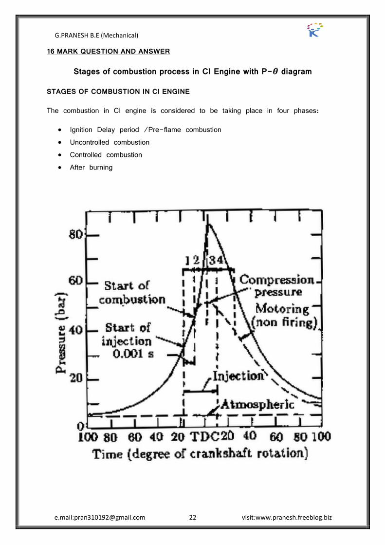
The combustion in CI engine is considered to be taking place in four phases:
Ignition Delay period /Pre-flame combustion Uncontrolled combustion Controlled combustion After burning

G.PRANESH B.E (Mechanical)
e.mail:[email protected] 23 visit:www.pranesh.freeblog.biz
i.Ignition Delay period /Pre-flame combustion
The fuel does not ignite immediately upon injection into the combustion chamber. There is a definite period of inactivity between the time of injection and the actual burning this period is known as the ignition delay period.
In Figure 2. the delay period is shown on pressure crank angle (or time) diagram between points a and b. Point ‚a‛ represents the time of injection and point ‚b‛ represents the time of combustion. The ignition delay period can be divided into two parts, the physical delay and the chemical delay.
The delay period in the CI engine exerts a very great influence on both engine design performance. It is of extreme importance because of its effect on both the combustion rate and knocking and also its influence on engine starting ability and the presence of smoke in the exhaust.

G.PRANESH B.E (Mechanical)
e.mail:[email protected] 24 visit:www.pranesh.freeblog.biz
ii.Period of Rapid Combustion
The period of rapid combustion also called the uncontrolled combustion, is that phase in which the pressure rise is rapid. During the delay period, a considerable amount of fuel is accumulated in combustion chamber, these accumulated fuel droplets burns very rapidly causing a steep rise in pressure.
The period of rapid combustion is counted from end of delay period or the beginning of the combustion to the point of maximum pressure on the indicator diagram. The rate of heat-release is maximum during this period. This is also known as uncontrolled combustion phase, because it is difficult to control the amount of burning / injection during the process of burning.
It may be noted that the pressure reached during the period of rapid combustion will depend on the duration of the delay period (the longer the delay the more rapid and higher is the pressure rise since more fuel would have been present in the cylinder before the rate of burning comes under control).
iii.Period of Controlled Combustion
The rapid combustion period is followed by the third stage, the controlled combustion. The temperature and pressure in the second stage are so high that fuel droplets injected burn almost as they enter and find the necessary oxygen and any further pressure rise can be controlled by injection rate. The period of controlled combustion is assumed to end at maximum cycle temperature.
iv.Period of After-Burning
Combustion does not stop with the completion of the injection process. The unburnt and partially burnt fuel particles left in the combustion chamber start burning as soon as they come into contact with the oxygen. This process continues for a certain duration called the after-burning period. This burning may continue in expansion stroke up to 70 to 80% of crank travel from TDC.
G.PRANESH B.E (Mechanical)
e.mail:[email protected] 25 visit:www.pranesh.freeblog.biz
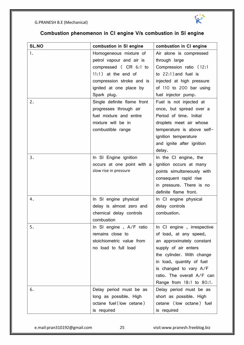
Combustion phenomenon in CI engine V/s combustion in SI engine
SL.NO combustion in SI engine combustion in CI engine 1. Homogeneous mixture of
petrol vapour and air is compressed ( CR 6:1 to 11:1) at the end of compression stroke and is ignited at one place by Spark plug.
Air alone is compressed through large Compression ratio (12:1 to 22:1)and fuel is injected at high pressure of 110 to 200 bar using fuel injector pump.
2. Single definite flame front progresses through air fuel mixture and entire mixture will be in combustible range
Fuel is not injected at once, but spread over a Period of time. Initial droplets meet air whose temperature is above self-ignition temperature and ignite after ignition delay.
3. In SI Engine ignition occurs at one point with a slow rise in pressure
In the CI engine, the ignition occurs at many points simultaneously with consequent rapid rise in pressure. There is no definite flame front.
4. In SI engine physical delay is almost zero and chemical delay controls combustion
In CI engine physical delay controls combustion.
5. In SI engine , A/F ratio remains close to stoichiometric value from no load to full load
In CI engine , irrespective of load, at any speed, an approximately constant supply of air enters the cylinder. With change in load, quantity of fuel is changed to vary A/F ratio. The overall A/F can Range from 18:1 to 80:1.
6. Delay period must be as long as possible. High octane fuel(low cetane) is required
Delay period must be as short as possible. High cetane (low octane) fuel is required

G.PRANESH B.E (Mechanical)
e.mail:[email protected] 26 visit:www.pranesh.freeblog.biz
PHENOMENON OF DIESEL KNOCK
Factors affecting knocking in SI engines
Knocking is violet gas vibration and audible sound produced by extreme pressure differentials leading to the very rapid rise during the early part of uncontrolled second phase of combustion.
In C.I. engines the injection process takes place over a definite interval of time. Consequently, as the first few droplets injected are passing through the ignition lag period, additional droplets are being injected into the chamber. If the ignition delay is longer, the actual burning of the first few droplets is delayed and a greater quantity of fuel droplets gets accumulated in the chamber. When the actual burning commences, the additional fuel can cause too rapid a rate of pressure rise, as shown on pressure crank angle diagram above, resulting in Jamming of forces against the piston (as if struck by a hammer) and rough engine operation. If the ignition delay is quite long, so much fuel can accumulate that the rate of pressure rise is almost instantaneous. Such, a situation produces extreme pressure differentials and violent gas vibration known as knocking (diesel knock), and is evidenced by audible knock. The phenomenon is similar to that in the SI engine. However, in SI Engine knocking occurs near the end of combustion whereas in CI engine, knocking the occurs near the beginning of combustion.
G.PRANESH B.E (Mechanical)
e.mail:[email protected] 27 visit:www.pranesh.freeblog.biz
Delay period is directly related to Knocking in CI engine. An extensive delay period can be due to following factors:
A low compression ratio permitting only a marginal self-ignition temperature to be reached.
A low combustion pressure due to worn out piston, rings and bad valves Low cetane number of fuel Poorly atomized fuel spray preventing early combustion Coarse droplet formation due to malfunctioning of injector parts like spring Low intake temperature and pressure of air
METHODS OF CONTROLING DIESEL KNOCK
We have discussed the factors which are responsible for the detonation in the previous sections. If these factors are controlled, then the detonation can be avoided.
Using a better fuel:
Higher CN fuel has lower delay period and reduces knocking tendency.
Controlling the Rate of Fuel Supply:
By injecting less fuel in the beginning and then more fuel amount in the combustion chamber detonation can be controlled to a certain extent. Cam shape of suitable profile can be designed for this purpose.
Knock reducing fuel injector:
This type of injector avoids the sudden increase in pressure inside the combustion chamber because of accumulated fuel. This can be done by arranging the injector so that only small amount of fuel is injected first. This can be achieved by using two or more injectors arranging in out of phase.
By using Ignition accelerators:
C N number can be increased by adding chemical called dopes. The two chemical dopes are used are ethyl-nitrate and amyle ”nitrate in concentration of 8.8 gm/Litre and 7.7 gm/Litre. But these two increase the NOx emissions.

G.PRANESH B.E (Mechanical)
e.mail:[email protected] 28 visit:www.pranesh.freeblog.biz
COMPARISON OF KNOCK IN SI AND CI ENGINES
It may be interesting to note that knocking in spark-ignition engines and compression ignition engines is fundamentally due to the auto ignition of the fuel-air mixture. In both the cases, the knocking depends on the auto ignition lag of the fuel-air mixture. But careful examination of knocking phenomenon in SI and CI engines reveals the following differences:
1. In spark ignition engines, auto ignition of end gas away from the spark plug, most likely near the end of combustion causes knocking. But in compression engines the auto ignition of charge causing knocking is at the start of combustion.
2. In order to avoid knocking in SI engine, it is necessary to prevent auto ignition of the end gas to take place at all. In CI engine, the earliest auto ”ignition is necessary to avoid knocking
3. The knocking in SI engine takes place in homogeneous mixture, therefore , the rate of pressure rise and maximum pressure is considerably high. In case of CI engine, the mixture is not homogenous and hence the rate of pressure is lower than in SI engine.
4. In CI engine only air is compressed, therefore there is no question of Pre-ignition in CI engines as in SI engines.
5. It is lot more easily to distinguish between knocking and non-knocking condition in SI engines as human ear easily finds the difference. However in CI engines, normal ignition itself is by auto-ignition and rate of pressure rise under the normal
G.PRANESH B.E (Mechanical)
e.mail:[email protected] 29 visit:www.pranesh.freeblog.biz
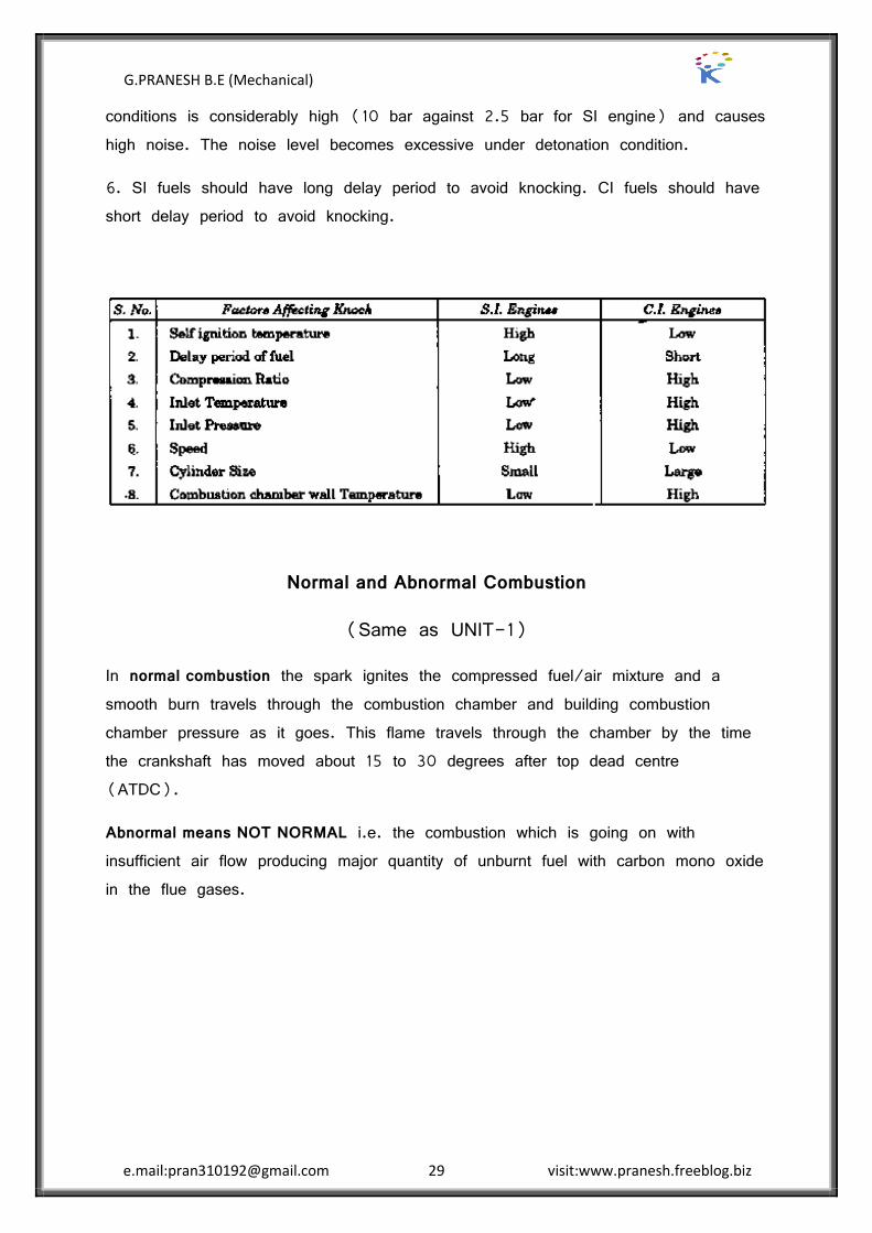
conditions is considerably high (10 bar against 2.5 bar for SI engine) and causes high noise. The noise level becomes excessive under detonation condition.
6. SI fuels should have long delay period to avoid knocking. CI fuels should have short delay period to avoid knocking.
Normal and Abnormal Combustion
(Same as UNIT-1)
In normal combustion the spark ignites the compressed fuel/air mixture and a smooth burn travels through the combustion chamber and building combustion chamber pressure as it goes. This flame travels through the chamber by the time the crankshaft has moved about 15 to 30 degrees after top dead centre (ATDC).
Abnormal means NOT NORMAL i.e. the combustion which is going on with insufficient air flow producing major quantity of unburnt fuel with carbon mono oxide in the flue gases.
G.PRANESH B.E (Mechanical)
e.mail:[email protected] 30 visit:www.pranesh.freeblog.biz
Direct and Indirect Injection Systems
Direct injection diesel engine
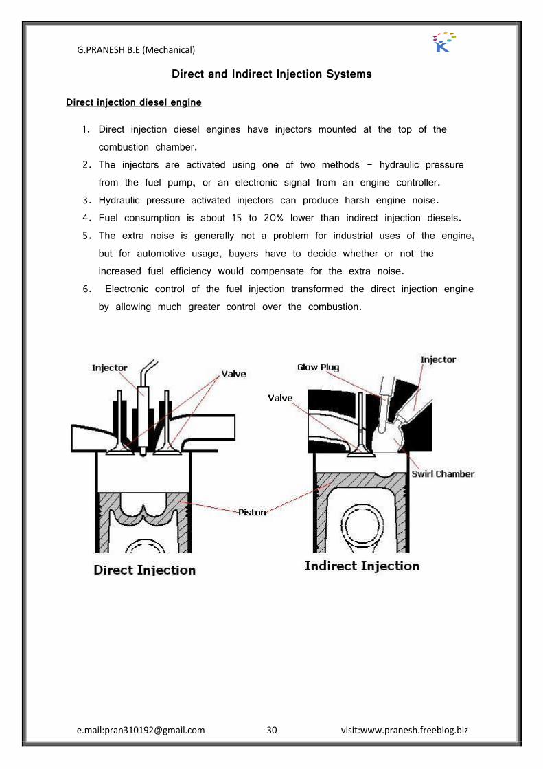
1. Direct injection diesel engines have injectors mounted at the top of the combustion chamber.
2. The injectors are activated using one of two methods - hydraulic pressure from the fuel pump, or an electronic signal from an engine controller.
3. Hydraulic pressure activated injectors can produce harsh engine noise. 4. Fuel consumption is about 15 to 20% lower than indirect injection diesels. 5. The extra noise is generally not a problem for industrial uses of the engine,
but for automotive usage, buyers have to decide whether or not the increased fuel efficiency would compensate for the extra noise.
6. Electronic control of the fuel injection transformed the direct injection engine by allowing much greater control over the combustion.
G.PRANESH B.E (Mechanical)
e.mail:[email protected] 31 visit:www.pranesh.freeblog.biz
Indirect injection diesel engine
1. An indirect injection diesel engine delivers fuel into a chamber off the combustion chamber, called a pre-chamber or ante-chamber, where combustion begins and then spreads into the main combustion chamber, assisted by turbulence created in the chamber.
2. This system allows for a smoother, quieter running engine, and because combustion is assisted by turbulence, injector pressures can be lower, about 100 bar (10 MPa; 1,500 psi), using a single orifice tapered jet injector.
3. Mechanical injection systems allowed high-speed running suitable for road vehicles (typically up to speeds of around 4,000 rpm).
4. The pre-chamber had the disadvantage of increasing heat loss to the engine's cooling system, and restricting the combustion burn, which reduced the efficiency by 5”10%.[35] Indirect injection engines are cheaper to build and it is easier to produce smooth, quiet-running vehicles with a simple mechanical system.
5. In road-going vehicles most prefer the greater efficiency and better controlled emission levels of direct injection.
6. Indirect injection diesels can still be found in the many ATV diesel applications.
TYPES OF COMBUSTION CHAMBERS- CI Engines
C I engine combustion chambers are classified into two categories:
1. OPEN INJECTION (DI) TYPE:
This type of combustion chamber is also called an Open combustion chamber. In this type the entire volume of combustion chamber is located in the main cylinder and the fuel is injected into this volume.
2. INDIRECT INJECTION (IDI) TYPE:
in this type of combustion chambers, the combustion space is divided into two parts, one part in the main cylinder and the other part in the cylinder head. The fuel ”injection is effected usually into the part of chamber located in the cylinder head. These chambers are classified

G.PRANESH B.E (Mechanical)
e.mail:[email protected] 32 visit:www.pranesh.freeblog.biz
DIRECT INJECTION CHAMBERS – OPEN COMBUSTION CHAMBERS
Shallow Depth Chamber:
In shallow depth chamber the depth of the cavity provided in the piston is quite small. This chamber is usually adopted for large engines running at low speeds. Since the cavity diameter is very large, the squish is negligible.
Hemispherical Chamber:
This chamber also gives small squish. However, the depth to diameter ratio for a cylindrical chamber can be varied to give any desired squish to give better performance.
Cylindrical Chamber:
This design was attempted in recent diesel engines. This is a modification of the cylindrical chamber in the form of a truncated cone with base angle of 30°. The swirl was produced by masking the valve for nearly 1800 of circumference. Squish can also be varied by varying the depth.
Toroidal Chamber:
The idea behind this shape is to provide a powerful squish along with the air movement, similar to that of the familiar smoke ring, within the toroidalchamber. Due to powerful squish the mask needed on inlet valve is small and there is better utilisation of oxygen. The cone angle of spray for this type of chamber is 150° to 160°.

G.PRANESH B.E (Mechanical)
e.mail:[email protected] 33 visit:www.pranesh.freeblog.biz
INDIRECT INJECTION COMBUSTION CHAMBERS
Ricardo’s Swirl Chamber:
Swirl chamber consists of a spherical shaped chamber separated from the engine cylinder and located in the cylinder head. In to this chamber, about 50% of the air is transferred during the compressionstroke. A throat connects the chamber to the cylinder which enters the chamber in a tangential direction so that the air coming into this chamber is given a strong rotary movement inside the swirl chamber and after combustion, the products rush back into the cylinder through same throat at much higher velocity. The use of single hole of larger diameter for the fuel spray nozzle is often important consideration for the choice of swirl chamber engine.
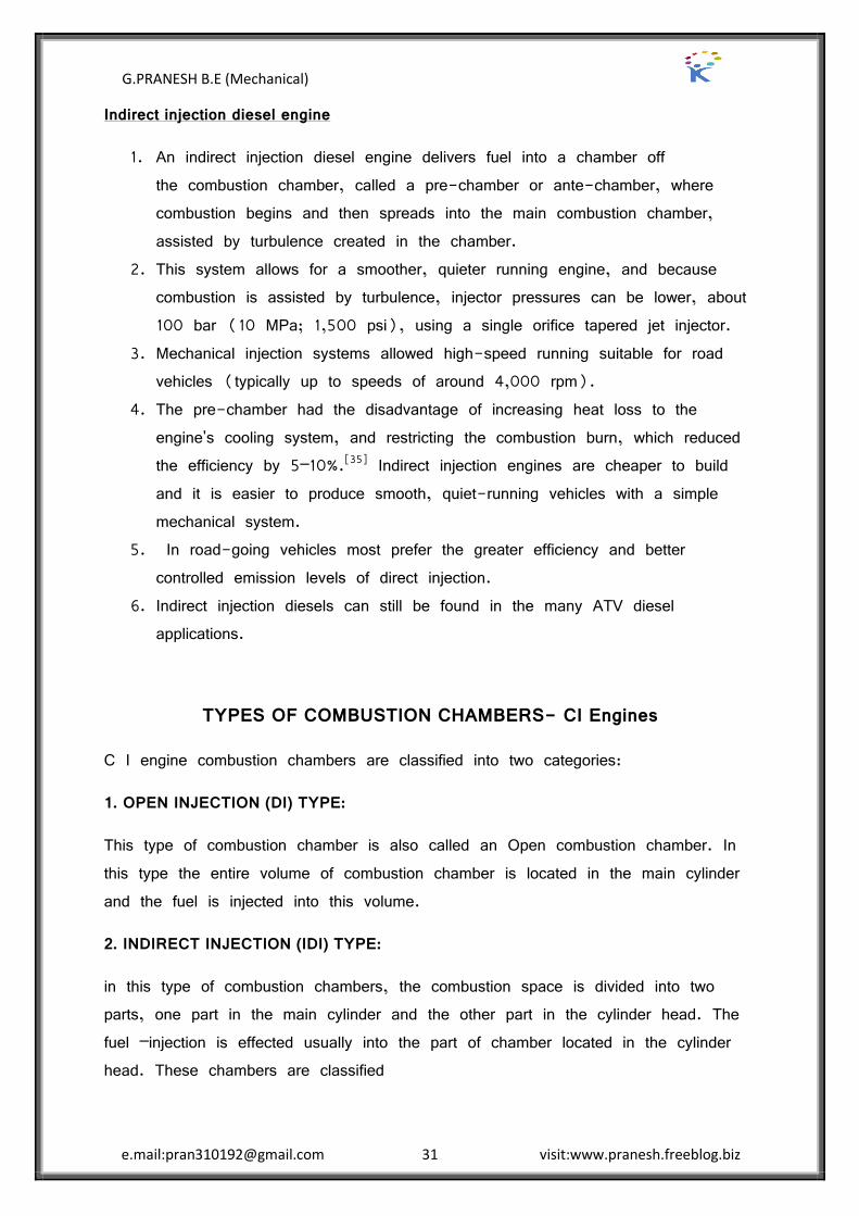
Pre Combustion Chamber
Typical pre-combustion chamber consists of an anti-chamber connected to the main chamber through a number of small holes (compared to a relatively large passage in the swirl chamber). The pre-combustion chamber is located in the cylinder head and its volume accounts for about 40% of the total combustion, space. During the compression stroke the piston forces the air into the pre-combustion chamber. The fuel is injected into the pre-chamber and the combustion is initiated. The resulting pressure rise forces the flaming droplets together with some air and their combustion products to rush out into the main cylinder at high velocity through the small holes.
G.PRANESH B.E (Mechanical)
e.mail:[email protected] 34 visit:www.pranesh.freeblog.biz
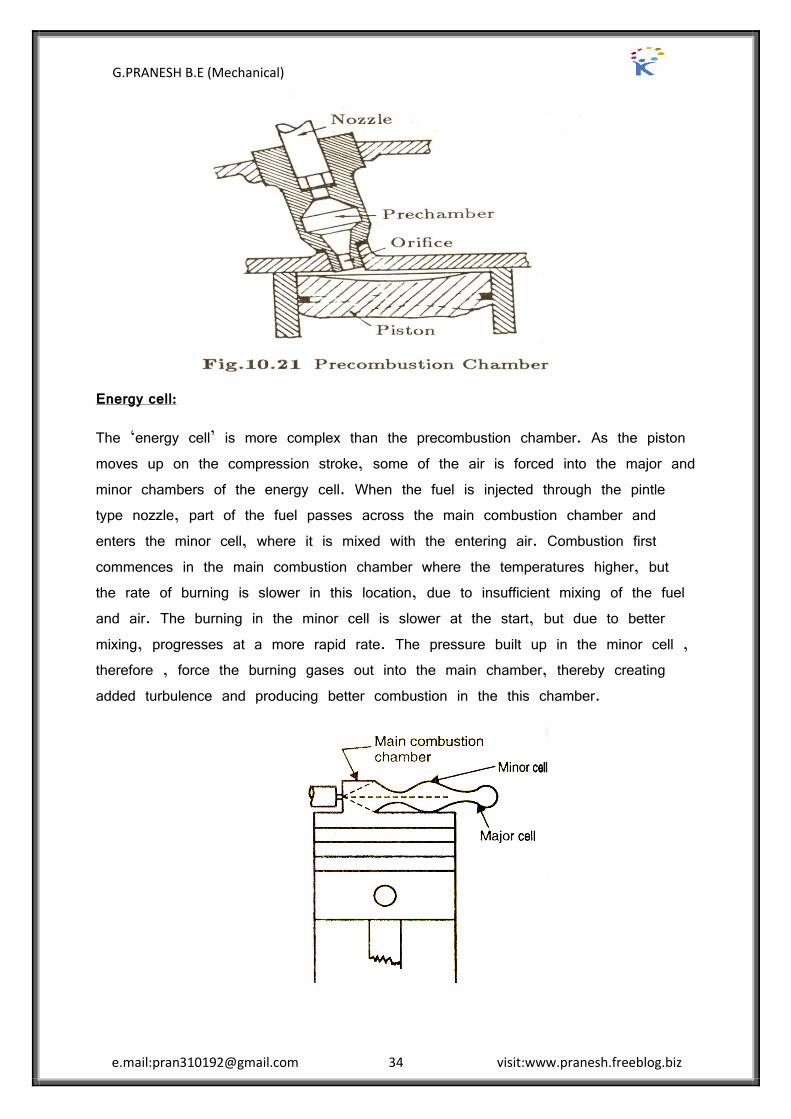
Energy cell:
The ‘energy cell’ is more complex than the precombustion chamber. As the piston moves up on the compression stroke, some of the air is forced into the major and minor chambers of the energy cell. When the fuel is injected through the pintle type nozzle, part of the fuel passes across the main combustion chamber and enters the minor cell, where it is mixed with the entering air. Combustion first commences in the main combustion chamber where the temperatures higher, but the rate of burning is slower in this location, due to insufficient mixing of the fuel and air. The burning in the minor cell is slower at the start, but due to better mixing, progresses at a more rapid rate. The pressure built up in the minor cell , therefore , force the burning gases out into the main chamber, thereby creating added turbulence and producing better combustion in the this chamber.

G.PRANESH B.E (Mechanical)
e.mail:[email protected] 35 visit:www.pranesh.freeblog.biz
Turbocharger
A turbocharger or turbo is a forced induction device used to allow more power to be produced for an engine of a given size. A turbocharged engine can be more powerful and efficient than a naturally aspirated engine because the turbine forces more air, and proportionately more fuel, into the combustion chamber than atmospheric pressure alone.

G.PRANESH B.E (Mechanical)
e.mail:[email protected] 36 visit:www.pranesh.freeblog.biz
Working principle a turbocharger is a small radial fan pump driven by the energy of the exhaust gases of an engine. A turbocharger consists of a turbine and a compressor on a shared shaft. The turbine section of a turbocharger is a heat engine in itself. It converts the heat energy from the exhaust to power, which then drives the compressor, compressing ambient air and delivering it to the air intake manifold of the engine at higher pressure, resulting in a greater mass of air entering each cylinder. In some instances, compressed air is routed through an intercooler before introduction to the intake manifold. Because a turbocharger is a heat engine, and is converting otherwise wasted exhaust heat to power, it compresses the inlet air to the engine more efficiently than a supercharger.
Components the turbocharger has four main components. The turbine (almost always a radial turbine) and impeller/compressor wheels are each contained within their own folded conical housing on opposite sides of the third component, the centre housing/hub rotating assembly (CHRA). The housings fitted around the compressor impeller and turbine collect and direct the gas flow through the wheels as they spin. The size and shape can dictate some performance characteristics of the overall turbocharger. Often the same basic turbocharger assembly will be available from the manufacturer with multiple housing choices for the turbine and sometimes the compressor cover as well. This allows the designer of the engine system to tailor the compromises between performance, response, and efficiency to application or preference. Twin-scroll designs have two valve-operated exhaust gas inlets, a smaller sharper angled one for quick response and a larger less angled one for peak performance. The turbine and impeller wheel sizes also dictate the amount of air or exhaust that can be flowed through the system, and the relative efficiency at which they operate. Generally, the larger the turbine wheel and compressor wheel, the larger the flow capacity. Measurements and shapes can vary, as well as curvature and number of blades on the wheels. Variable geometry turbochargers are further developments of these ideas.
G.PRANESH B.E (Mechanical)
e.mail:[email protected] 37 visit:www.pranesh.freeblog.biz
The centre hub rotating assembly (CHRA) houses the shaft which connects the compressor impeller and turbine. It also must contain a bearing system to suspend the shaft, allowing it to rotate at very high speed with minimal friction. For instance, in automotive applications the CHRA typically uses a thrust bearing or ball bearing lubricated by a constant supply of pressurized engine oil. The CHRA may also be considered "water cooled" by having an entry and exit point for engine coolant to be cycled. Water cooled models allow engine coolant to be used to keep the lubricating oil cooler, avoiding possible oil coking from the extreme heat found in the turbine. The development of air-foil bearings has removed this risk.
Introduction to Thermodynamic Analysis of CI Engine Combustion process
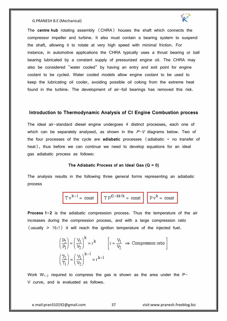
The ideal air-standard diesel engine undergoes 4 distinct processes, each one of which can be separately analysed, as shown in the P-V diagrams below. Two of the four processes of the cycle are adiabatic processes (adiabatic = no transfer of heat), thus before we can continue we need to develop equations for an ideal gas adiabatic process as follows:
The Adiabatic Process of an Ideal Gas (Q = 0)
The analysis results in the following three general forms representing an adiabatic process
Process 1-2 is the adiabatic compression process. Thus the temperature of the air increases during the compression process, and with a large compression ratio (usually > 16:1) it will reach the ignition temperature of the injected fuel.
Work W1-2 required to compress the gas is shown as the area under the P-V curve, and is evaluated as follows.

G.PRANESH B.E (Mechanical)
e.mail:[email protected] 38 visit:www.pranesh.freeblog.biz
An alternative approach using the energy equation takes advantage of the adiabatic process (Q1-2 = 0) results in a much simpler process:
Process 2-3 the fuel is injected and combusted and this is represented by a constant pressure expansion process. At state 3 ("fuel cutoff") the expansion process continues adiabatically with the temperature decreasing until the expansion is complete.
Process 3-4 is thus the adiabatic expansion process. The total expansion work is Wexp = (W2-3 + W3-4) and is shown as the area under the P-V diagram and is analysed as follows:

G.PRANESH B.E (Mechanical)
e.mail:[email protected] 39 visit:www.pranesh.freeblog.biz
Process 4-1 represents the constant volume heat rejection process. In an actual Diesel engine the gas is simply exhausted from the cylinder and a fresh charge of air is introduced.
The net work Wnet done over the cycle is given by: Wnet = (Wexp + W1-2), whereas before the compression work W1-2 is negative (work done on the system).
In the Air-Standard Diesel cycle engine the heat input Qin occurs by combusting the fuel which is injected in a controlled manner, ideally resulting in a constant pressure expansion process 2-3 as shown below. At maximum volume (bottom dead centre) the burnt gasses are simply exhausted and replaced by a fresh charge of air. This is represented by the equivalent constant volume heat rejection process Qout = -Q4-1. Both processes are analyzed as follows:

G.PRANESH B.E (Mechanical)
e.mail:[email protected] 40 visit:www.pranesh.freeblog.biz
At this stage we can conveniently determine the engine efficiency in terms of the heat flow as follows:
G.PRANESH B.E (Mechanical)
e.mail:[email protected] 41 visit:www.pranesh.freeblog.biz
UNIT III ENGINE EXHAUST EMISSION CONTROL
2 MARK QUESTION AND ANSWER
1. What are the major exhaust emissions?
The major exhaust emissions are
a. Unburnt hydrocarbons (HC) b. Oxides of carbon (co and co2)
c. Oxides of nitrogen (NO and NO2) d. Oxides of sulphur (SO2 and SO3)
e. Particulates f. Soot and smoke
2. What are the causes for hydrocarbon emission from S.I Engine?
The causes for hydro carbon emission from S.I engine are
1. Incomplete combustion. 2. Crevice volume and flow in crevices. 3. Leakage past the exhaust valve. 4. Valve overlap. 5. Deposits on walls. 6. Oil on combustion chamber walls.
3. What are the reasons for incomplete combustion in SI engine?
Incomplete combustion is due to
a. Improper mixing due to incomplete mixing of the air and fuel. Some fuel particles do not find the oxygen to react with this cause the emissions.
b. Flame quenching: As the flame goes very close to the walls it gets quenched at the walls leaving a small volume of unreacted air fuel mixture.
4. What are the reasons for flame quenching?
The reason for flame quenching is the expansion of gases.
(i) As the piston moves down from TDC to BDC during power stroke, expansion of the gases lowers both pressure and temperature with in the cylinder. This makes combustion slow and finally quenches the flame and causes the emissions. (ii) High exhaust gas contamination causes poor combustion and which in turn causes quenching during expansion.

G.PRANESH B.E (Mechanical)
e.mail:[email protected] 42 visit:www.pranesh.freeblog.biz
(iii) As the flame goes very close to the walls it gets quenched at the walls leaving a small volume of unreacted air-fuel mixture.
5. How the oil consumption increases in IC engines and what are the effects
Often as engines ages, due o wear, clearance between the pistons and cylinder wall increases. This increases oil consumption contributes to increases in the emissions in three ways.
a. There is an added crevices volume.
b. There is added absorption ” desorption of fuel in the thicker oil film on cylinder walls
c. There is oil burned in the combustion process
6. Write a short note on carbon monoxide emissions
Carbon monoxide is a colourless and odourless but a poisonous gas. It is generated in an engine when it is operated with a fuel rich equivalence ratio. Poor mixing, local rich regions, and incomplete combustion will also be the source for co emissions.
7. What is photochemical smog?
NOx is the primary causes of photochemical smog, Smog is formed by the photochemical reaction of automobiles exhaust and atmospheric air in the presence of sunlight.
NO2 + energy from sunlight NO + O +smog
8. What are soot particles?
Soot particles are clusters of solid carbon sheres. These spheres have diameter from 9nm to 90nm (1nm = 10-9). But most of them are within the range of 15 ” 30nm. The spheres are solid carbon with HC and traces of other components absorbed on the surface. Single soot particles may contain up to 5000 carbon spheres.

G.PRANESH B.E (Mechanical)
e.mail:[email protected] 43 visit:www.pranesh.freeblog.biz
9. Which is the most effective after treatment for reducing engine emissions?
The catalytic converter is the most effective after treatment for reducing engine emissions found on most automobiles. Co can be oxidized to CO2 and H2O in exhaust system and thermal converters if the temperature is held at 600- 700 . If certain catalysts are present, the temperature needed to sustain these oxidation processes is reduced to 250 - 300 , making for a much more attractive system.
10. What is a catalyst?
A catalyst is a substance that accelerates chemical reaction by lowering the energy needed for it to proceed. The catalyst is not consumed in the reaction and so functions indefinitely unless degraded by heat age contaminants or other factors.
11. List the materials used as catalyst.
The catalyst materials most commonly used are a. platinum b. palladium c. rhodium.
12. Why catalytic converter called as three way converters?
Catalytic converters are called as three way converters because they are used to reduce the concentration of CO, HC and NOx in the exhaust.
13. What are the types of ceramic structure used in catalytic convertor?
Inside the container is a process ceramic structure through which the exhaust gas flows.
a. The ceramic is a single honey comb structure with many flow passages.
b. Some converters use loose granular ceramic with the gas passing between the packed spheres.
14. List out the drawbacks of catalytic converters.
a. Sulphur offers unique problems for catalytic converters some catalyst promote the conversion of SO2 to SO3 which eventually converted to sulphuric acid. This degreds the catalytic convertor and contributes to acid rain.
b. Catalytic converters are not very efficient when they are cold. When an engine is started after not being operated for several hours it takes several minute for the
G.PRANESH B.E (Mechanical)
e.mail:[email protected] 44 visit:www.pranesh.freeblog.biz
converter to reach an efficient operating temperature called as cold start up problem.
15. What are the methods of catalytic converters preheating?
The methods of catalytic converters preheating included the following
a. By locating the converters close to the engine b. By having superinsulation
c. By employing electric preheating d. By using flame heating e. Incorporating thermal batteries.
16. List the invisible and visible emission
Invisible emission: Water vapour, carbon dioxide, oxides of nitrogen, unburnt hydrocarbons, carbon monoxide, aldehydes.
Visible emission: Smoke, particulate.
17. What are the methods of measuring the following emission?
a. Oxides of nitrogen = CHEMILUMINESCENCE ANALYZER
b. Carbon monoxide = NON DISPERSIVE INFRARED ANALYZER
c. Unburned hydrocarbons = FLAME IONIZATION DETECTOR (FID)

G.PRANESH B.E (Mechanical)
e.mail:[email protected] 45 visit:www.pranesh.freeblog.biz
16 MARK QUESTION AND ANSWER
SI/CI ENGINE EMISSIONS
1. Unburned Hydro Carbons
2. Carbon monoxide
3. Oxides of nitrogen
4. Oxides of sulphur and
5. Particulates including smoke
Pollutant formation in SI/CI Engine
Formation of NOX, HC/CO mechanism
Mechanism of NO formation:
The nitric oxide formation during the combustion process is the result of group of elementary reaction involving the nitrogen and oxygen molecules. Different mechanism proposed is discussed below.
a. Simple reaction between N2 and O2
N2 + O2 2 NO
This mechanism proposed by Eyzat and Guibet predicts NO concentrations much lower that those measured in I.C engines. According to this mechanism, the formation process is too slow for NO to reach equilibrium at peak temperatures and pressures in the cylinders.
b. Zeldovich Chai Reaction mechanism:
O2 2 O ------------- (1)
O + N2 NO + N ------ (2)
N + O2 NO + O ------ (3)
G.PRANESH B.E (Mechanical)
e.mail:[email protected] 46 visit:www.pranesh.freeblog.biz
The chain reactions are initiated by the equation (2) by the atomic oxygen, formed in equation (1) from the dissociation of oxygen molecules at the high temperatures reached in the combustion process. Oxygen atoms react with nitrogen molecules and produces NO and nitrogen atoms. In the equation (3) the nitrogen atoms react with oxygen molecule to form nitric oxide and atomic oxygen.
According to this mechanism nitrogen atoms do not start the chain reaction because their equilibrium concentration during the combustion process is relatively low compared to that of atomic oxygen. Experiments have shown that equilibrium concentrations of both oxygen atoms and nitric oxide molecules increase with temperature and with leaning of mixtures. It has also been observed that NO formed at the maximum cycle temperature does not decompose even during the expansion stroke when the gas temperature decreases.
In general it can be expected that higher temperature would promote the formation of NO by speeding the formation reactions. Ample O2 supplies would also increase the formation of NO. The NO levels would be low in fuel rich operations, i.e. A/F 15, since there is little O2 left to react with N2 after the hydrocarbons had reacted.
The maximum NO levels are formed with AFR about 10 percent above stoichiometric. More air than this reduces the peak temperature, since excess air must be heated from energy released during combustion and the NO concentration fall off even with additional oxygen.
Measurements taken on NO concentrations at the exhaust valve indicate that the concentration rises to a peak and then fall as the combustion gases exhaust from the cylinder. This is consistent with the idea that NO is formed in the bulk gases. The first gas exhausted is that near the exhaust valve followed by the bulk gases. The last gases out should be those from near the cylinder wall and should exhibit lower temperatures and lower NO concentration.

G.PRANESH B.E (Mechanical)
e.mail:[email protected] 47 visit:www.pranesh.freeblog.biz
Hydrocarbons formation:
Hydrocarbon exhaust emission may arise from three sources as
a. Wall quenching
b. Incomplete combustion of charge
c. Exhaust scavenging in 2-stroke engines
In an automotive type 4-stroke cycle engine, wall quenching is the predominant source of exhaust hydrocarbon under most operating conditions.
a. Wall quenching:
The quenching of flame near the combustion chamber walls is known as wall quenching. This is a combustion phenomenon which arises when the flame tries to propagate in the vicinity of a wall. Normally the effect of the wall is a slowing down or stopping of the reaction.
Because of the cooling, there is a cold zone next to the cooled combustion chamber walls. This region is called the quench zone. Because of the low temperature, the fuel-air mixture fails to burn and remains unburned.
Due to this, the exhaust gas shows a marked variation in HC emission. The first gas that exits is from near the valve and is relatively cool. Due to this it is rich in HC. The next part of gas that comes is from the hot combustion chamber and hence a low HC concentration. The last part of the gas that exits is scrapped off the cool cylinder wall and is relatively cool. Therefore it is also rich in HC emission.
b. Incomplete combustion:
Under operating conditions, where mixtures are extremely rich or lean, or exhaust gas dilution is excessive, incomplete flame propagation occurs during combustion and results in incomplete combustion of the charge.
Normally, the carburetor supplies air fuel mixture in the combustible range. Thus incomplete combustion usually results from high exhaust gas dilution arising from high vacuum operation such as idle or deceleration.

G.PRANESH B.E (Mechanical)
e.mail:[email protected] 48 visit:www.pranesh.freeblog.biz
However during transient operation, especially during warm up and deceleration it is possible that sometimes too rich or too lean mixture enters the combustion chamber resulting in very high HC emission.
Factors which promote incomplete flame propagation and misfire include:
a. Poor condition of the ignition system, including spark plug
b. Low charge temperature
c. Poor charge homogeneity
d. Too rich or lean mixture in the cylinder
e. Large exhaust residual quantity
f. Poor distribution of residuals with cylinder
Carburetion and mixture preparation, evaporation and mixing in the intake manifold, atomization at the intake valve and swirl and turbulence in the combustion chamber are some factors which influence gaseous mixture ration and degree of charge homogeneity including residual mixing.
The engine and intake system temperature resulting from prior operation of the engine affect charge temperature and can also affect fuel distribution.
Valve overlap, engine speed, spark timing, compression ratio, intake and exhaust system back pressure affect the amount and composition of exhaust residual. Fuel volatility of the fuel is also one of the main reasons.
c. Scavenging:
In 2-stroke engine a third source of HC emission results from scavenging of the cylinder with fuel air mixture. Due to scavenging part of the air fuel mixture blows through the cylinder directly into exhaust port and escapes combustion process completely. HC emission from a 2-Stroke petrol engine is comparatively higher than 4-Stroke petrol engine.

G.PRANESH B.E (Mechanical)
e.mail:[email protected] 49 visit:www.pranesh.freeblog.biz
Carbon monoxide Formation:
Carbon monoxide remains in the exhaust if the oxidation of CO to CO2 is not complete. This is because carbon monoxide is an intermediate product in the combustion process. Generally this is due to lack of sufficient oxygen. The emission levels of CO from gasoline engine are highly dependent on A/F ratio.
The amount of CO released reduces as the mixture is made leaner. The reason that the CO concentration does not drop to zero when the mixture is chemically correct and leaner arises from a combination of cycle to cycle and cylinder to cylinder mal distribution and slow CO reaction kinetics. Better carburetion and fuel distribution are key to low CO emission in addition to operating the engine at increased air-fuel ratio.
DIESEL ENGINE SMOKE EMISSION
Engine exhaust smoke is a visible indicator of the combustion process in the engine. Smoke is due to incomplete combustion. Smoke in diesel engine can be divided into three categories: blue, white and black.
Blue smoke:
It results from the burning of engine lubricating oil that reaches combustion chamber due to worn piston rings, cylinder liners and valve guides.
White or cold smoke:
It is made up of droplets of unburnt or partially burnt fuel droplets and is usually associated with the engine running at less than normal operating temperature after starting, long period of idling, operating under very light load, operating with leaking injectors and water leakage in combustion chamber. This smoke normally fades away as engine is warmed up and brought to normal stage.
Black or hot smoke:
It consists of unburnt carbon particles (0.5 ” 1 microns in diameter) and other solid products of combustion. This smoke appears after engine is warmed up and is accelerating or pulling under load.

G.PRANESH B.E (Mechanical)
e.mail:[email protected] 50 visit:www.pranesh.freeblog.biz
Formation of smoke in Diesel engines:
The main cause of smoke formation is known to be inadequate mixing of fuel and air. Smoke is formed when the local temperature is high enough to decompose fuel in a region where there is insufficient oxygen to burn the carbon that is formed. The formation of over-rich fuel air mixtures either generally or in localized regions will result in smoke. Large amounts of carbons will be formed during the early stage of combustion. This carbon appears as smoke if there is insufficient air, if there is insufficient mixing or if local temperatures fall below the carbon reaction temperatures (approximately 1000C) before the mixing occurs.
Acceptable performance of diesel engine is critically influenced by exhaust some emissions. Failure of engine to meet smoke legislation requirement prevents sale and particularly for military use, possible visibility by smoke is useful to enemy force. Diesel emissions give information on effectiveness of combustion, general performance and condition of engine
Particulates
Particulate matter comes from hydrocarbons, lead additives and sulphur dioxide. If lead is used with the fuel to control combustion almost 70% of the lead is airborne with the exhaust gasses. In that 30% of the particulates rapidly settle to the ground while remaining remains in the atmosphere. Lead is well known toxic compound.
Particulates when inhaled or taken along with food leads to respiratory problems and other infections.
Particulates when settle on the ground they spoil the nature of the object on which they are settling. Lead, a particulate is a slow poison and ultimately leads to death.
G.PRANESH B.E (Mechanical)
e.mail:[email protected] 51 visit:www.pranesh.freeblog.biz
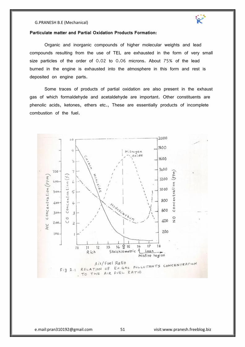
Particulate matter and Partial Oxidation Products Formation:
Organic and inorganic compounds of higher molecular weights and lead compounds resulting from the use of TEL are exhausted in the form of very small size particles of the order of 0.02 to 0.06 microns. About 75% of the lead burned in the engine is exhausted into the atmosphere in this form and rest is deposited on engine parts.
Some traces of products of partial oxidation are also present in the exhaust gas of which formaldehyde and acetaldehyde are important. Other constituents are phenolic acids, ketones, ethers etc., These are essentially products of incomplete combustion of the fuel.
G.PRANESH B.E (Mechanical)
e.mail:[email protected] 52 visit:www.pranesh.freeblog.biz
Greenhouse Effect
The greenhouse effect is a process by which thermal radiation from a planetary surface is absorbed by atmospheric greenhouse and is re-radiated in all directions. Since part of this re-radiation is back towards the surface, energy is transferred to the surface and the lower atmosphere. As a result, the temperature there is higher than it would be if direct heating by solar radiation were the only warming mechanism.
Greenhouse gases
By their percentage contribution to the greenhouse effect on Earth the four major gases are:
water vapour, 36–70%
carbon dioxide, 9–26%
methane, 4–9%
ozone, 3–7%
The greenhouse effect is the retention by the Earth’s atmosphere in the form of heat some of the energy that arrives from the Sun as light. Certain gases, including carbon dioxide (CO 2) and methane (CH 4), are transparent to most of the wavelengths of light arriving from the Sun but are relatively opaque to infrared or heat radiation; thus, energy passes through the Earth’s atmosphere on arrival, is converted to heat by absorption at the surface and in the atmosphere, and is not easily re-radiated into space. The same process is used to heat a solar greenhouse, only with glass, rather than gas, as the heat-trapping material. The greenhouse effects happen to maintain the Earth’s surface temperature within a range comfortable for living things; without it, the Earth’s surface would be much colder.
The greenhouse effect is mostly a natural phenomenon, but its intensity, according to a majority of climatologists, may be increasing because of increasing atmospheric concentrations of CO 2 and other greenhouse gases. These increased concentrations are occurring because of human activities, especially the burning of fossil fuels and the clearing of forests (which remove CO 2 from the atmosphere and store its carbon in cellulose, [C 6 H 10 O 5] n). A probable consequence

G.PRANESH B.E (Mechanical)
e.mail:[email protected] 53 visit:www.pranesh.freeblog.biz
of an intensification of Earth’s greenhouse effect will be a significant warming of the atmosphere. This in turn would result in important secondary changes, such as a rise in sea level (already occurring), variations in the patterns of precipitation. These, in turn, might accelerate the rate at which species are already being to extinction by human activity, and impose profound adjustments on human society.
G.PRANESH B.E (Mechanical)
e.mail:[email protected] 54 visit:www.pranesh.freeblog.biz
Methods of controlling emissions
1. NOx is decreased by
A. Decreasing the combustion chamber temperature
The combustion chamber temperature can be decreased by
1. Decreasing compression ratio
2. Retarding spark timing
3. Decreasing charge temperature
4. Decreasing engine speed
5. Decreasing inlet charge pressure
6. Exhaust gas recirculation
7. Increasing humidity
B. By decreasing oxygen available in the flame front
The amount of oxygen available in the chamber can be controlled by
1. Rich mixture
2. Stratified charge engine
3. Divided combustion chamber
2. Hydrocarbon emission can be decreased by
1. Decreasing the compression ratio
2. Retarding the spark
3. Increasing charge temperature
4. Increasing coolant temperature
5. Insulating exhaust manifold
6. Increasing engine speed
7. Lean mixture
G.PRANESH B.E (Mechanical)
e.mail:[email protected] 55 visit:www.pranesh.freeblog.biz
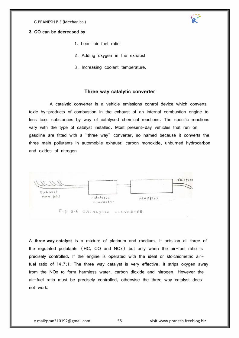
3. CO can be decreased by
1. Lean air fuel ratio
2. Adding oxygen in the exhaust
3. Increasing coolant temperature.
Three way catalytic converter
A catalytic converter is a vehicle emissions control device which converts toxic by-products of combustion in the exhaust of an internal combustion engine to less toxic substances by way of catalysed chemical reactions. The specific reactions vary with the type of catalyst installed. Most present-day vehicles that run on gasoline are fitted with a ‚three way‛ converter, so named because it converts the three main pollutants in automobile exhaust: carbon monoxide, unburned hydrocarbon and oxides of nitrogen
A three way catalyst is a mixture of platinum and rhodium. It acts on all three of the regulated pollutants (HC, CO and NOx) but only when the air-fuel ratio is precisely controlled. If the engine is operated with the ideal or stoichiometric air-fuel ratio of 14.7:1. The three way catalyst is very effective. It strips oxygen away from the NOx to form harmless water, carbon dioxide and nitrogen. However the air-fuel ratio must be precisely controlled, otherwise the three way catalyst does not work.

G.PRANESH B.E (Mechanical)
e.mail:[email protected] 56 visit:www.pranesh.freeblog.biz
Figure shows a three way catalytic converter. The front section( in the direction of gas flow) handles NOx and partly handles HC and CO. The partly treated exhaust gas is mixed with secondary air. The mixture of partly treated exhaust gas and secondary air flows into the rear section of the chamber. The two way catalyst present in the rear section takes care of HC and CO.
1. Reduction of nitrogen oxides to nitrogen and oxygen: 2NOx → xO2 + N2
2. Oxidation of carbon monoxide to carbon dioxide: 2CO + O2 → 2CO2
3. Oxidation of unburnt hydrocarbons (HC) to carbon dioxide and water: CxH2x+2 + [(3x+1)/2] O2 → xCO2 + (x+1) H2O.
Diesel particulate filter (Particulate Trap)
A diesel particulate filter (or DPF) is a device designed to remove diesel particulate matter or soot from the exhaust gas of a diesel engine. Wall-flow diesel particulate filters usually remove 85% or more of the soot and under certain conditions can attain soot removal efficiencies of close to 100%. Some filters are single-use, intended for disposal and replacement once full of accumulated ash. Others are designed to burn off the accumulated particulate either passively through the use of a catalyst or by active means such as a fuel burner which heats the filter to soot combustion temperatures; engine programming to run when the filter is full in a manner that elevates exhaust temperature or produces high amounts
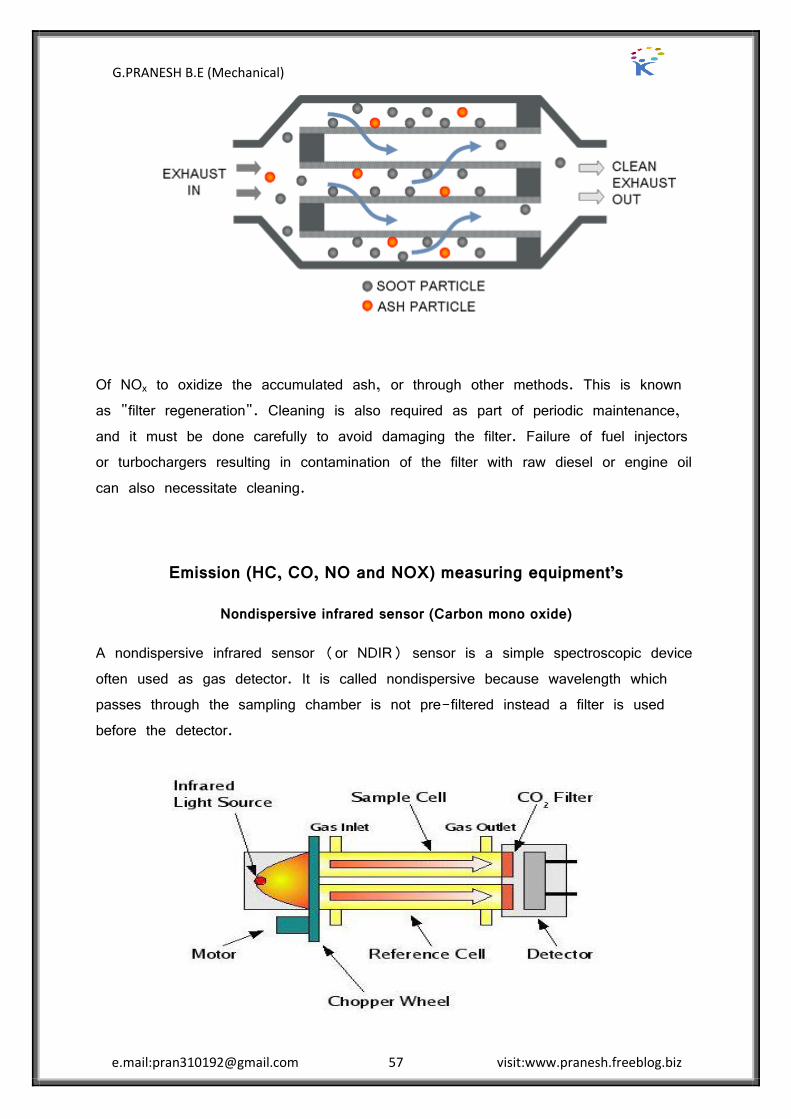
G.PRANESH B.E (Mechanical)
e.mail:[email protected] 57 visit:www.pranesh.freeblog.biz
Of NOx to oxidize the accumulated ash, or through other methods. This is known as "filter regeneration". Cleaning is also required as part of periodic maintenance, and it must be done carefully to avoid damaging the filter. Failure of fuel injectors or turbochargers resulting in contamination of the filter with raw diesel or engine oil can also necessitate cleaning.
Emission (HC, CO, NO and NOX) measuring equipment’s
Nondispersive infrared sensor (Carbon mono oxide)
A nondispersive infrared sensor (or NDIR) sensor is a simple spectroscopic device often used as gas detector. It is called nondispersive because wavelength which passes through the sampling chamber is not pre-filtered instead a filter is used before the detector.

G.PRANESH B.E (Mechanical)
e.mail:[email protected] 58 visit:www.pranesh.freeblog.biz
The main components are an infrared source (lamp), a sample chamber or light tube, a wavelength sample chamber, and gas concentration is measured electro-optically by its absorption of a specific wavelength in the infrared (IR). The IR light is directed through the sample chamber towards the detector. In parallel there is another chamber with an enclosed reference gas, typically nitrogen. The detector has an optical filter in front of it that eliminates all light except the wavelength that the selected gas molecules can absorb. Ideally other gas molecules do not absorb light at this wavelength, and do not affect the amount of light reaching the detector to compensate for interfering components. For instance, CO2 and H2O often initiate cross sensitivity in the infrared spectrum. As many measurements in the IR area are cross sensitive to H2O it is difficult to analyse for instance SO2 and NO2 in low concentrations using the infrared light principle. The IR signal from the source is usually chopped or modulated so that thermal background signals can be offset from the desired signal
Flame ionization detector (Hydro Carbon)
The operation of the FID is based on the detection of ions formed during combustion of organic compounds in a hydrogen flame. The generation of these ions is proportional to the concentration of organic species in the sample gas stream. Hydrocarbons generally have molar response factors that are equal to number of carbon atoms in their molecule, while oxygenates and other species that contain heteroatoms tend to have a lower response factor. Carbon monoxide and carbon dioxide are not detectable by FID.

G.PRANESH B.E (Mechanical)
e.mail:[email protected] 59 visit:www.pranesh.freeblog.biz
In order to detect these ions, two electrodes are used to provide a potential difference. The positive electrode doubles as the nozzle head where the flame is produced. The other, negative electrode is positioned above the flame. When first designed, the negative electrode was either tear-drop shaped or angular piece of platinum. Today, the design has been modified into a tubular electrode, commonly referred to as a collector plate. The ions thus are attracted to the collector plate and upon hitting the plate, induce a current. This current is measured with a high-impedancepicoammeter and fed into an integrator. The manner in which the final data is displayed is based on the computer and software. In general, a graph is displayed that has time on the x-axis and total ion on the y-axis.
The current measured corresponds roughly to the proportion of reduced carbon atoms in the flame. Specifically how the ions are produced is not necessarily understood, but the response of the detector is determined by the number of carbon atoms (ions) hitting the detector per unit time. This makes the detector sensitive to the mass rather than the concentration, which is useful because the response of the detector is not greatly affected by changes in the carrier gas flow rate.
Chemiluminescence Detector (NOx measurement)
Chemiluminescence (sometimes "chemoluminescence") is the emission of light (luminescence), as the result of a chemical reaction. There may also be limited emission of heat. Given reactants A and B, with an excited intermediate ◊,
[A] + [B] → [◊] → [Products] + light
For example, if [A] is luminol and [B] is hydrogen peroxide in the presence of a suitable catalyst we have:
Luminol + H2O2 → 3-APA [◊] → 3-APA + light
Where:
Where 3-APA is 3-aminophthalate
3-APA [◊] is the vibronic excited state fluorescing as it decays to a lower energy level.
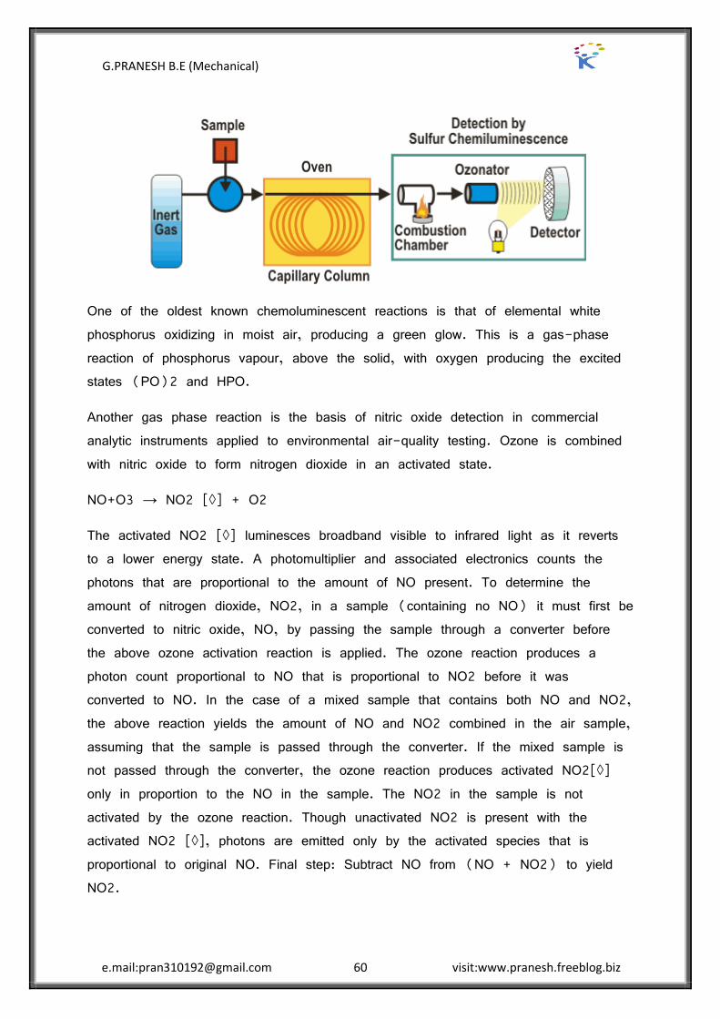
G.PRANESH B.E (Mechanical)
e.mail:[email protected] 60 visit:www.pranesh.freeblog.biz
One of the oldest known chemoluminescent reactions is that of elemental white phosphorus oxidizing in moist air, producing a green glow. This is a gas-phase reaction of phosphorus vapour, above the solid, with oxygen producing the excited states (PO)2 and HPO.
Another gas phase reaction is the basis of nitric oxide detection in commercial analytic instruments applied to environmental air-quality testing. Ozone is combined with nitric oxide to form nitrogen dioxide in an activated state.
NO+O3 → NO2 [◊] + O2
The activated NO2 [◊] luminesces broadband visible to infrared light as it reverts to a lower energy state. A photomultiplier and associated electronics counts the photons that are proportional to the amount of NO present. To determine the amount of nitrogen dioxide, NO2, in a sample (containing no NO) it must first be converted to nitric oxide, NO, by passing the sample through a converter before the above ozone activation reaction is applied. The ozone reaction produces a photon count proportional to NO that is proportional to NO2 before it was converted to NO. In the case of a mixed sample that contains both NO and NO2, the above reaction yields the amount of NO and NO2 combined in the air sample, assuming that the sample is passed through the converter. If the mixed sample is not passed through the converter, the ozone reaction produces activated NO2[◊] only in proportion to the NO in the sample. The NO2 in the sample is not activated by the ozone reaction. Though unactivated NO2 is present with the activated NO2 [◊], photons are emitted only by the activated species that is proportional to original NO. Final step: Subtract NO from (NO + NO2) to yield NO2.
G.PRANESH B.E (Mechanical)
e.mail:[email protected] 61 visit:www.pranesh.freeblog.biz
Smoke and Particulate measurement
(Refer Particulate Trap same unit)
A diesel particulate filter (or DPF) is a device designed to remove diesel particulate matter or soot from the exhaust gas of a diesel engine.
Indian Driving Cycles and emission norms
Driving Cycle:
The driving cycle for both CVS-1 and CVS-3 cycles is identical. It involves various accelerations, decelerations and cruise modes of operation. The car is started after soaking for 12 hours in a 60-80 F ambient. A trace of the driving cycle is shown in figure. Miles per hour versus time in seconds are plotted on the scale. Top speed is 56.7 mph. Shown for comparison is the FTP or California test cycle. For many advanced fast warm-up emission control systems, the end of the cold portion on the CVS test is the second idle at 125 seconds. This occurs at 0.68 miles. In the CVS tests, emissions are measured during cranking, start-up and for five seconds after ignition are turned off following the last deceleration. Consequently high emissions from excessive cranking are included. Details of operation for manual transmission vehicles as well as restart procedures and permissible test tolerance are included in the Federal Registers.
CVS-1 system:
The CVS-1 system, sometimes termed variable dilution sampling, is designed to measure the true mass of emissions. The system is shown in figure. A large positive displacement pump draws a constant volume flow of gas through the system. The exhaust of the vehicle is mixed with filtered room air and the mixture is then drawn through the pump. Sufficient air is used to dilute the exhaust in order to avoid vapour condensation, which could dissolve some pollutants and reduce measured values. Excessive dilution on the other hand, results in very low concentration with attendant measurement problems. A pump with capacity of 30-350 cfm provides sufficient dilution for most vehicles.
Before the exhaust-air mixture enters the pump, its temperature is controlled to within +or ” 10F by the heat exchanger. Thus constant density is maintained in
G.PRANESH B.E (Mechanical)
e.mail:[email protected] 62 visit:www.pranesh.freeblog.biz
the sampling system and pump. A fraction of the diluted exhaust stream is drawn off by a pump P2 and ejected into an initially evacuated plastic bag. Preferably, the bag should be opaque and manufactured of Teflon or Teldar. A single bag is used for the entire test sample in the CVS-1 system.
Because of high dilution, ambient traces of HC, CO or NOx can significantly increase concentrations in the sample bag. A charcoal filter is employed for leveling ambient HC measurement. To correct for ambient contamination a bag of dilution air is taken simultaneously with the filling of the exhaust bag.
HC, CO and NOx measurements are made on a wet basis using FID, NDIR and chemiluminescent detectors respectively. Instruments must be constructed to accurately measure the relatively low concentrations of diluted exhaust.
Bags should be analyzed as quickly as possible preferably within ten minutes after the test because reactions such as those between NO, NO2 and HC can occur within the bag quite quickly and change the test results.
CVS-3 SYSTEM:
The CVS-3 system is identical to the CVS-1 system except that three exhaust sample bags are used. The normal test is run from a cold start just like the CVS-1 test. After deceleration ends at 505 seconds, the diluted exhaust flow is switched from the transient bag to the stabilized bag and revolution counter number 1 is switched off and number 2 is activated. The transient bag is analyzed immediately. The rest of the test is completed in the normal fashion and the stabilized bag analyzed. However in the CVS-3 test ten minutes after the test ends the cycle is begun and again run until the end of deceleration at 505 seconds. This second run is termed the hot start run.
A fresh bag collects what is termed the hot transient sample. It is assumed that the second half of the hot start run is the same as the second half of the cold start run and is not repeated. In all, three exhaust sample bags are filled. An ambient air sample bag is also filled simultaneously.
G.PRANESH B.E (Mechanical)
e.mail:[email protected] 63 visit:www.pranesh.freeblog.biz
STANDARDS IN INDIA:
The Bureau of Indian Standards (BIS) is one of the pioneering organizations to initiate work on air pollution control in India. At present only the standards for the emission of carbon monoxide are being suggested by BIS given in IS: 9057-1986. These are based on the size of the vehicle and to be measured under idling conditions. The CO emission values are 5.5 percent for 2 or 3 wheeler vehicles with engine displacement of 75cc or less, 4.5 percent for higher sizes and 3.5 percent for four wheeled vehicles.
IS: 8118-1976 Smoke Emission Levels for Diesel vehicles prescribes the smoke limit for diesel engine as 75 Hatridge units or 5.2 Bosch units at full load and 60-70 percent rated speed or 65 Hatridge units under free acceleration conditions.

G.PRANESH B.E (Mechanical)
e.mail:[email protected] 64 visit:www.pranesh.freeblog.biz
UNIT IV ALTERNATE FUELS
2 MARK QUESTION AND ANSWER
1. Write the advantage and disadvantage of alcohol as a fuel?
The advantages of alcohols a fuel are:
It is a high octane fuel with antiknock index number (octane number) of over 100.
Alcohols have low sulphur content in the fuel. It produces less overall emissions when compared with gasoline
Disadvantages:
Alcohols have poor ignition characteristics in general. There is a possibility of vapour lock in fuel delivery system. It has poor cold weather starting characteristics due to low vapor pressure
and evaporation.
2. What is the problem with gasoline-alcohol mixture as a fuel?
Problems with gasoline-alcohol mixture as a fuel are the tendency for alcohol to combine with any water present. When this happens the alcohol separates to locally from the gasoline, resulting in a non-homogenous mixture. This causes the engine to run erratically due to the large air-fuel ratio difference between the two fuels.
3. Write the sources for methanol?
Methanol can be obtained from many sources, both fossil and renewable. These include coal, petroleum, natural gas, biomass, wood landfills and even the ocean.
4. Write the source for ethanol?
Ethanol can be made from ethylene (or) from fermentation of grains and sugar. Much of it is made from sugarcane, sugar beets, and even cellulose (wood and paper).

G.PRANESH B.E (Mechanical)
e.mail:[email protected] 65 visit:www.pranesh.freeblog.biz
5. What are the techniques of using alcohol in diesel engine fuel?
The techniques of using alcohol in diesel engine are:
Alcohol diesel emulsions. Dual fuel injection. Alcohol fumigation. Surface ignition of alcohols.
6. What are the methods are adopted for induction of alcohol into intake manifold?
The methods are adopted for induction of alcohol into intake manifold micro fog unit, pneumatic spray nozzle, vaporizer, carburettor and fuel injector.
7. List the advantages of hydrogen as an IC engine?
Advantages
Low emissions. Fuel availability. Fuel leakage to environment is not a pollutant High energy continent per volume when stored as a liquid.
8. List the disadvantages of using hydrogen as a fuel?
Disadvantages
Difficult to re fuel. Fuel cost would be high at present day’s technology and availability. Poor engine volumetric efficiency. High NOx emission because of high flame.
9. Write the methods for hydrogen can be used in SI engines?
Hydrogen can be used in SI engines by three methods
By manifold induction By direct introduction of hydrogen into the cylinder. By supplementing gasoline.
G.PRANESH B.E (Mechanical)
e.mail:[email protected] 66 visit:www.pranesh.freeblog.biz
10. List the advantages and disadvantages of natural gas?
Advantages:
Octane number is around 120, which makes it a very good SI engines fuel. Low engine emissions Fuel is fairly abundant worldwide. Disadvantages: Low energy density resulting in low engine performance. Low engine volumetric efficiency because it is a gaseous fuel. Refuelling is a slow process.
11. Write the two types of LPG used in automobiles engine?
Two type of LPG used in automobile engines:
One is propane and the other is butane, sometimes in mixture of propane and butane is used as LPG in auto mobile engine.
12. What are the advantages of LPG?
LPG mixes with air at all temperatures. LPG has high antiknock characteristics. There is no crack case dilution, because the fuel is in the form of vapour.
13. Write the disadvantages of LPG?
A special fuel feed system is required for liquid petroleum gas. A good cooling system is quite necessary. The vehicle weight is increased due to the use of heavy pressure cylinder
for storing LPG.
14. Write the improvements required for the LPG vehicle in future?
Effort must be made to have more LPG filling stations at convenient locations, so that LPG tank can be filled up easily.
Safety devices are to be introduced to prevent accidents due to explosion of gas cylinders (or) Leakage in the gas pipes.
G.PRANESH B.E (Mechanical)
e.mail:[email protected] 67 visit:www.pranesh.freeblog.biz
16 MARK QUESTION AND ANSWER
Alternative Fuel
Alternative fuels, known as non-conventional or advanced fuels, are any materials or substances that can be used as fuels, other than conventional fuels. Conventional fuels include: fossil fuels (petroleum (oil), coal, propane, and natural gas), as well as nuclear materials such as uranium and thorium, as well as
artificial radioisotope fuels that are made in nuclear reactors.
Types:
Alcohols Vegetable oils Bio-diesel Bio-gas Natural Gas Liquefied Petroleum Gas Hydrogen
Alcohols
Alcohol has been used as a fuel. The first four aliphatic alcohols (methanol, ethanol, propanol, and butanol) are of interest as fuels because they can be synthesized chemically or biologically, and they have characteristics which allow them to be used in internal combustion engines. The general chemical formula for alcohol fuel is CnH2n+1OH.
Most methanol are produced from natural gas, although it can be produced from biomass using very similar chemical processes. Ethanol is commonly produced from biological material through fermentation processes. This mixture may also not be purified by simple distillation, as it forms an azeotropic mixture. Biobutanol has the advantage in combustion engines in that its energy density is closer to gasoline than the simpler alcohols (while still retaining over 25% higher octane rating); however, biobutanol is currently more difficult to produce than ethanol or methanol. When obtained from biological materials and/or biological processes, they are known as bio alcohols (e.g. "bioethanol"). There is no chemical difference between biologically produced and chemically produced alcohols.
G.PRANESH B.E (Mechanical)
e.mail:[email protected] 68 visit:www.pranesh.freeblog.biz
One advantage shared by the four major alcohol fuels is their high octane rating. This tends to increase their fuel efficiency and largely offsets the lower energy density of vehicular alcohol fuels (as compared to petrol/gasoline and diesel fuels), thus resulting in comparable "fuel economy" in terms of distance per volume metrics, such as kilometres per liter, or miles per gallon.
Advantages
Is cheaper and more efficient and does not damage environment as much. Made from a renewable energy source, corn in the US, sugar cane in
Brazil, or anything else that can produce ethanol. It reduces certain greenhouse emissions, CO and UHC's Higher octane rating, engine can have higher compression
Disadvantages
Less energy content, it has 1/3 less energy than gasoline .Emits cancer causing emissions 40x more than gasoline. Acetaldehyde, and
formaldehyde. Takes more energy to produce that it you get out. only 83% back.
Material incapability. Ethanol destroys aluminium, rubber, gaskets, and many other things, so
special materials are used in FFV's and to transport it. May corrode parts of engine, you may have to fill in more often as alcohol
runs out quickly.
Methanol
Methanol fuel has been proposed as a future biofuel, often as an alternative to the hydrogen economy. Methanol has a long history as a racing fuel. Early Grand Prix Racing used blended mixtures as well as pure methanol. The use of the fuel was primarily used in North America after the war.[clarification needed] However, methanol for racing purposes has largely been based on methanol produced from syngas derived from natural gas and therefore this methanol would not be considered a biofuel. Methanol is a possible biofuel, however when the syngas is derived from biomass. In theory, methanol can also be produced from carbon dioxide and hydrogen using nuclear power or any renewable energy source, although this is not likely to be economically viable on an industrial scale (see
G.PRANESH B.E (Mechanical)
e.mail:[email protected] 69 visit:www.pranesh.freeblog.biz
methanol economy). Compared to bioethanol, the primary advantage of methanol biofuel is its much greater well-to-wheel efficiency. This is particularly relevant in temperate climates where fertilizers are needed to grow sugar or starch crops to make ethanol, whereas methanol can be produced from lignocellulose (woody) biomass.
Methanol combustion is: 2CH3OH + 3O2 → 2CO2 + 4H2O + heat
Ethanol
Ethanol is already being used extensively as a fuel additive and the use of ethanol fuel alone or as part of a mix with gasoline is increasing. Compared to methanol its primary advantage is that it is less corrosive and additionally the fuel is non-toxic, although the fuel will produce some toxic exhaust emissions.
Ethanol combustion is: C2H5OH + 3O2 → 2CO2 + 3H2O + heat
Vegetable oil fuel
Vegetable oil is an alternative fuel for diesel engines and for heating oil burners. For engines designed to burn diesel fuel, the viscosity of vegetable oil must be lowered to allow for proper atomization of the fuel; otherwise incomplete combustion and carbon build up will ultimately damage the engine.
Benefits of vegetable oil run vehicles:
CO2 neutral Economical, cheaper than diesel Excellent system-energy efficiency (from raw "crude" to refined product) Sulphur-free Protects crude oil resources 100% biodegradable Non-hazardous for ground, water, and air in case of a spill Low fire hazard (flashpoint > 220°C) Practical to refuel at home Easy to store, more ecological than bio-diesel A chance for the farming community and agriculture
G.PRANESH B.E (Mechanical)
e.mail:[email protected] 70 visit:www.pranesh.freeblog.biz
Disadvantages of vegetable oil run vehicles:
Loss of space and/or vehicle load capacity due to additional fuel storage Loss of manufacturer guarantee in new vehicles for use of an alternative
fuel Motor oil needs to be replaced more often in a direct injection engine as
a safety precaution to avoid build-up Currently no public network of filling stations are available, must refuel at
home
Biodiesel
Fuel that is made from natural elements such as plants, vegetables, and reusable materials. This type of fuel is better for the atmosphere because, unlike other fuels, it does not give off harmful chemicals which can influence the environment negatively. The popularity of biodiesel fuel is consistently increasing as people search out alternative energy resources.
Biodiesel refers to a vegetable oil- or animal fat-based diesel fuel consisting of long-chain alkyl (methyl, propyl or ethyl) esters. Biodiesel is typically made by chemically reacting lipids (e.g., vegetable oil, animal fat with an alcohol producing fatty acid esters.
Biodiesel is meant to be used in standard diesel engines and is thus distinct from the vegetable and waste oils used to fuel converted diesel engines. Biodiesel can be used alone, or blended with petro diesel. Biodiesel can also be used as a low carbon alternative to heating oil.
Advantages: Using biofuels can reduce the amount of greenhouse gases emitted. They are a much cleaner source of energy than conventional sources.
As more and more biofuel is created there will be increased energy security for the country producing it, as they will not have to rely on imports or foreign volatile markets.
First generation biofuels can save up to 60% carbon emissions and second.
G.PRANESH B.E (Mechanical)
e.mail:[email protected] 71 visit:www.pranesh.freeblog.biz
Generation biofuels can save up to 80%.Biofuels will create a brand new job infrastructure and will help support local economies. This is especially true in third world countries. There can be a reduction in fossil fuel use.
Biofuel operations help rural development. Biodiesel can be used in any diesel vehicle and it reduces the number of
vibrations, smoke and noise produced. Biodiesel is biodegradable.
Disadvantages:
Biofuel development and production is still heavily dependent on Oil. As other plants are replaced, soil erosion will grow. A lot of water is used to water the plants, especially in dry climates. Deforestation in South America and South Eastern Asia causes loss of
habitat for animals and for indigenous people living there. New technologies will have be developed for vehicles for them to use these
fuels. This will increase their prices significantly
Biogas
Biogas typically refers to a gas produced by the breakdown of organic matter in the absence of oxygen. It is a renewable energy source, like solar and wind energy. Furthermore, biogas can be produced from regionally available raw materials and recycled waste and is environmentally friendly and CO2 neutral.
Biogas is produced by the anaerobic digestion or fermentation of biodegradable materials such as manure, sewage, municipal waste, green waste, plant material, and crops. Biogas comprises primarily methane (CH4) and carbon dioxide (CO2) and may have small amounts of hydrogen sulphide (H2S), moisture and siloxanes.
The gases methane, hydrogen, and carbon monoxide (CO) can be combusted or oxidized with oxygen. This energy release allows biogas to be used as a fuel. Biogas can be used as a fuel in any country for any heating purpose, such as cooking. It can also be used in anaerobic digesters where it is typically used in a gas engine to convert the energy in the gas into electricity and heat. Biogas can be compressed, much like natural gas, and used to power motor vehicles.

G.PRANESH B.E (Mechanical)
e.mail:[email protected] 72 visit:www.pranesh.freeblog.biz
Advantages of Biogas Energy
It’s a renewable source of energy. It’s a comparatively lesser pollution generating energy. Biomass energy helps in cleanliness in villages and cities. It provides manure for the agriculture and gardens. There is tremendous potential to generate biogas energy. Biomass energy is relatively cheaper and reliable. It can be generated from everyday human and animal wastes, vegetable and
agriculture left-over etc. Recycling of waste reduces pollution and spread of diseases. Heat energy that one gets from biogas is 3.5 times the heat from burning
wood. Because of more heat produced the time required for cooking is lesser.
Disadvantages of Biogas Energy
Cost of construction of biogas plant is high, so only rich people can use it. Continuous supply of biomass is required to generate biomass energy. Some people don’t like to cook food on biogas produced from sewage
waste. Biogas plant requires space and produces dirty smell. Due to improper construction many biogas plants are working inefficiently. It is difficult to store biogas in cylinders. Transportation of biogas through pipe over long distances is difficult. Many easily grown grains like corn, wheat are being used to make ethanol.
This can have bad consequences if too much of food crop is diverted for use as fuel.
Crops which are used to produce biomass energy are seasonal and are not available over whole year.

G.PRANESH B.E (Mechanical)
e.mail:[email protected] 73 visit:www.pranesh.freeblog.biz
Natural gas
Natural gas is a naturally occurring hydrocarbon gas mixture consisting primarily of methane, but commonly including varying amounts of other hydrocarbons, carbon dioxide, nitrogen and hydrogen sulfide. Natural gas is an energy source often used for heating, cooking, and electricity generation. It is also used as fuel for vehicles and as a chemical feedstock in the manufacture of plastics and other commercially important organic chemicals.
Natural gas is found in deep underground natural rock formations or associated with other hydrocarbon reservoirs in coal beds and as methane clathrates. Petroleum is also another resource found in proximity to and with natural gas. Most natural gas was created over time by two mechanisms: biogenic and thermogenic. Biogenic gas is created by methanogenic organisms in marshes, bogs, landfills, and shallow sediments. Deeper in the earth, at greater temperature and pressure, thermogenic gas is created from buried organic material.
Advantages:
Natural gas (largely methane) burns more cleanly than the other fossil fuels (45% less carbon dioxide emitted than coal and 30% less than oil)
It is easily transported via pipelines and fairly easily using tankers (land and sea)
It can be piped into homes to provide heating and cooking and to run a variety of appliances.
Where homes are not piped, it can be supplied in small tanks. It can be used as a fuel for vehicles (cars, trucks and jet engines)
where it is cleaner than gasoline or diesel. It is used to produce ammonia for fertilizers, and hydrogen, as well as
in the production of some plastics and paints. It's relatively abundant, clean burning and seems easy to distribute. It's also lighter than air, so if there is a leak it will tend to dissipate,
unlike propane, which is heavier than air and pools into explosive pockets.
It can be used for heating, cooking, hot water, clothes dryer, backup generator power, and so forth.

G.PRANESH B.E (Mechanical)
e.mail:[email protected] 74 visit:www.pranesh.freeblog.biz
Some places will supply it to your house by way of underground pipes. Natural gas is more economical than electricity, It is faster when used in cooking and water heating and most gas
appliances are cheaper than electrical ones. Gas appliances also do not create unhealthy electrical fields in your
house.
Disadvantages: Even though it is cleaner than coal and oil, it still contributes a large
amount of carbon dioxide to greenhouse gases. By itself natural gas is mostly methane, which is 21 times more
dangerous for greenhouse warming than carbon dioxide so any leakage of the gas (from animals, landfills, melting tundra, etc.) contributes strongly to greenhouse emissions.
If your house is not properly insulated it can be very expensive. It can leak, potentially causing an explosion.
LIQUEFIED PETROLEUM GAS (LPG)
Liquefied petroleum gas, also called LPG, GPL, LP Gas, liquid petroleum gas or simply propane or butane, is a flammable mixture of hydrocarbon gases used as a fuel in heating appliances and vehicles. LPG is prepared by refining petroleum or "wet" natural gas, and is almost entirely derived from fossil fuel sources, being manufactured during the refining of petroleum (crude oil), or extracted from petroleum or natural gas streams as they emerge from the ground. LPG is a mixture of propane and butane (this is called autogas).
Relative fuel consumption of LPG is about ninety percent of that of gasoline by volume.
LPG has higher octane number of about 112, which enables higher compression ratio to be employed and gives more thermal efficiency.
Due to gaseous nature of LPG fuel distribution between cylinders is improved and smoother acceleration and idling performance is achieved.
Fuel consumption is also better. Engine life is increased for LPG engine as cylinder bore wear is reduced &
combustion chamber and spark plug deposits are reduced.
G.PRANESH B.E (Mechanical)
e.mail:[email protected] 75 visit:www.pranesh.freeblog.biz
As LPG is stored under pressure, LPG tank is heavier and requires more space than gasoline tank.
There is reduction in power output for LPG operation than gasoline operation.
Starting load on the battery for an LPG engine is higher than gasoline engine due to higher ignition system energy required.
LPG system requires more safety. In case of leakage LPG has tendency to accumulate near ground as it is heavier than air.
This is hazardous as it may catch fire. Volume of LPG required is more by 15 to 20% as compared to gasoline. LPG operation increases durability of engine and life of exhaust system is
increased. LPG has lower carbon content than gasoline or diesel and produces less
CO2which plays a major role in global warming during combustion.
The normal components of LPG are propane (C3H8) and butane (C4H10). Small concentrations of other hydrocarbons may also be present.
Methane - 0%
Ethane - 0.20%
Propane - 57.30%
Butane - 41.10%
Pentane - 1.40%
Advantages
LPG is cheaper than petrol (up to 50%) It produces less exhaust emissions than petrol It is better for the engine and it can prolong engine life In some vehicles, it can provide better performance Has a higher octane rating than petrol (108 compared to 91)

G.PRANESH B.E (Mechanical)
e.mail:[email protected] 76 visit:www.pranesh.freeblog.biz
Disadvantages
It isn't highly available The initial cost for converting your vehicle to LPG can cost up to
$3000. However the average car can repay the cost of the conversion in about 2 years
It has a lower energy density than petrol No new passenger cars come readily fitted with LPG (they have to be
converted) The gas tank takes up a considerable amount of space in the car boot
Hydrogen fuel
Hydrogen fuel is a zero-emission fuel which uses electrochemical cells or combustion in internal engines, to power vehicles and electric devices. It is also used in the propulsion of spacecraft and can potentially be mass-produced and commercialized for passenger vehicles and aircraft.
Hydrogen is one of two natural elements that combine to make water. Hydrogen is not an energy source, but an energy carrier because it takes a great deal of energy to extract it from water. It is useful as a compact energy source in fuel cells and batteries.
Hydrogen is the lightest and most abundant element in the universe. It can be produced from a number of feedstock’s in a variety of ways. The production method thought to be most environmentally benign is the electrolysis of water, but probably the most common source of hydrogen is the steam reforming of natural gas. Once produced, hydrogen can be stored as a gas, liquid, or solid and distributed as required. Liquid storage is currently the preferred method, but it is very costly. Hydrogen-powered vehicles can use internal combustion engines or fuel cells. They can also be hybrid vehicles of various combinations. When hydrogen is used as a gaseous fuel in an internal combustion engine, its very low energy density compared to liquid fuels is a major drawback requiring greater storage space for the vehicle to travel a similar distance to gasoline

G.PRANESH B.E (Mechanical)
e.mail:[email protected] 77 visit:www.pranesh.freeblog.biz
Advantages:
Emits only water vapour, assuming there is no leakage of hydrogen gas
It can store up to 3x as much energy as conventional natural gas.
Disadvantages:
Leakage of H gas (see above) will have detrimental impacts on the stratosphere (California Institute of Technology)
Production of hydrogen gas currently relies on natural gas and electrolysis and to replace all the vehicles would require 10x as much as currently is used
Storage is really tough because hydrogen is such a low density gas Distribution and infrastructure needs to be refurbished to cope with hydrogen,
which can metals by making them brittle Use in fuel cells requires catalysts, which usually require a component metal
(most often platinum). Platinum is extremely rare, expensive and environmentally unsound to produce.

G.PRANESH B.E (Mechanical)
e.mail:[email protected] 78 visit:www.pranesh.freeblog.biz
General properties of Alternative fuels
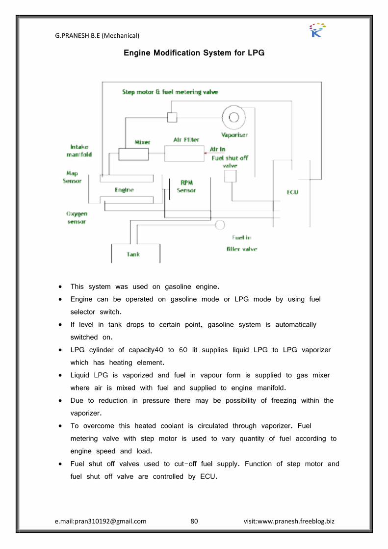
G.PRANESH B.E (Mechanical)
e.mail:[email protected] 80 visit:www.pranesh.freeblog.biz
Engine Modification System for LPG
This system was used on gasoline engine. Engine can be operated on gasoline mode or LPG mode by using fuel
selector switch. If level in tank drops to certain point, gasoline system is automatically
switched on. LPG cylinder of capacity40 to 60 lit supplies liquid LPG to LPG vaporizer
which has heating element. Liquid LPG is vaporized and fuel in vapour form is supplied to gas mixer
where air is mixed with fuel and supplied to engine manifold. Due to reduction in pressure there may be possibility of freezing within the
vaporizer. To overcome this heated coolant is circulated through vaporizer. Fuel
metering valve with step motor is used to vary quantity of fuel according to engine speed and load.
Fuel shut off valves used to cut-off fuel supply. Function of step motor and fuel shut off valve are controlled by ECU.

G.PRANESH B.E (Mechanical)
e.mail:[email protected] 81 visit:www.pranesh.freeblog.biz
Intake manifold has MAP sensor which measures manifold pressure & sends signal to ECU.
Oxygen sensor is located in exhaust which measures oxygen in exhaust and sends signals accordingly to ECU.
ECU receives these signals and calculates how much fuel is to be supplied and sends signal to fuel metering valve.
RPM sensor measures speed and sends signal to ECU. ECU decides amount of fuel to be supplied depending of engine speed and
sends signals to fuel metering valve. LPG with composition of 60 % propane and 40 % butane was used.
Octane no of LPG used was 88.
Engine Design modification for all other Alternative Fuels
Spark plugs
Use cold rated spark plugs to avoid spark plug electrode temperatures exceeding the auto-ignition limit and causing backfire. Cold rated spark plugs can be used since there are hardly any spark plug deposits to burn off.
Ignition system
Avoid uncontrolled ignition due to residual ignition energy by properly grounding the ignition system or changing the ignition cable’s electrical resistance. Alternatively, the spark plug gap can be decreased to lower the ignition voltage.
Injection system
Provide a timed injection, either using port injection and programming the injection timing such that an initial air cooling period is created in the initial phase of the intake stroke and the end of injection is such that all fuel is inducted, leaving no fuel in the manifold when the intake valve closes; or using direct injection during the compression stroke.
Hot spots
Avoid hot spots in the combustion chamber that could initiate pre-ignition or backfire.
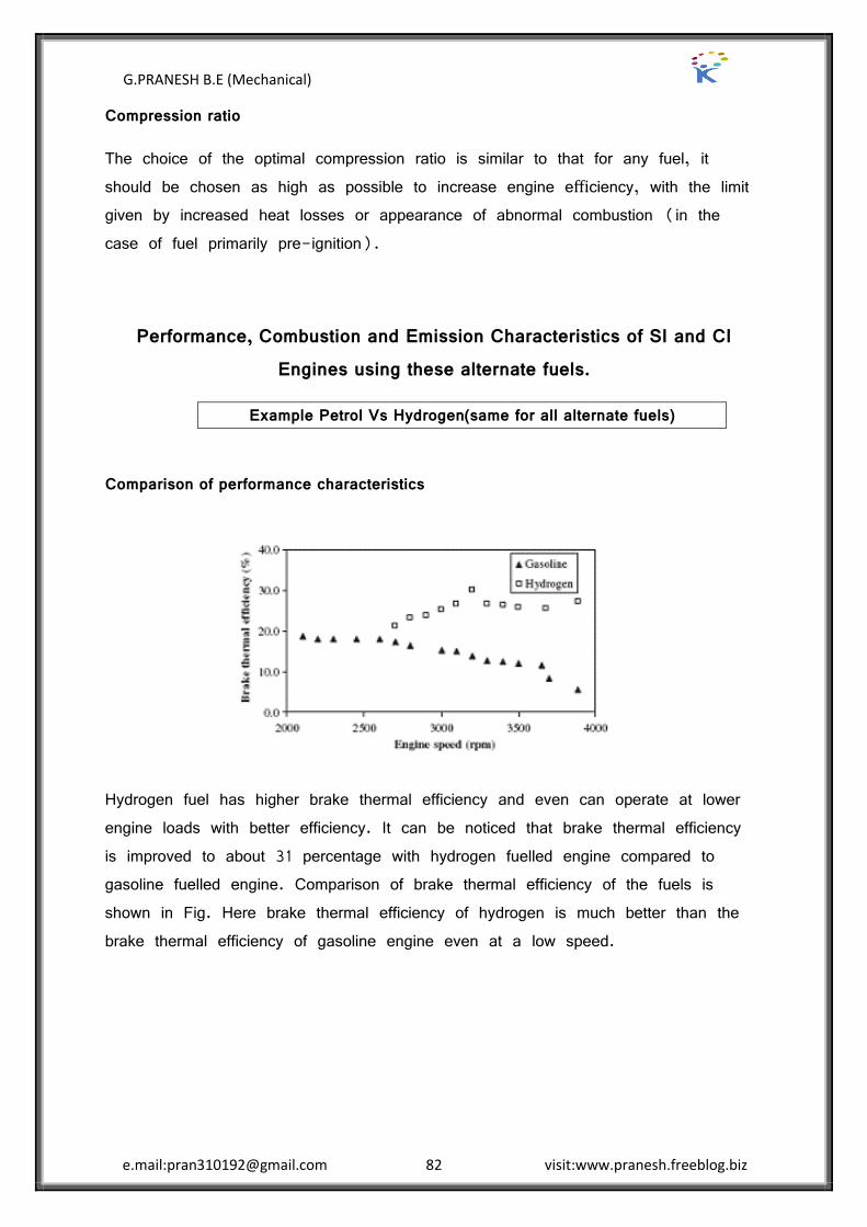
G.PRANESH B.E (Mechanical)
e.mail:[email protected] 82 visit:www.pranesh.freeblog.biz
Compression ratio
The choice of the optimal compression ratio is similar to that for any fuel, it should be chosen as high as possible to increase engine efficiency, with the limit given by increased heat losses or appearance of abnormal combustion (in the case of fuel primarily pre-ignition).
Performance, Combustion and Emission Characteristics of SI and CI Engines using these alternate fuels.
Example Petrol Vs Hydrogen(same for all alternate fuels)
Comparison of performance characteristics
Hydrogen fuel has higher brake thermal efficiency and even can operate at lower engine loads with better efficiency. It can be noticed that brake thermal efficiency is improved to about 31 percentage with hydrogen fuelled engine compared to gasoline fuelled engine. Comparison of brake thermal efficiency of the fuels is shown in Fig. Here brake thermal efficiency of hydrogen is much better than the brake thermal efficiency of gasoline engine even at a low speed.
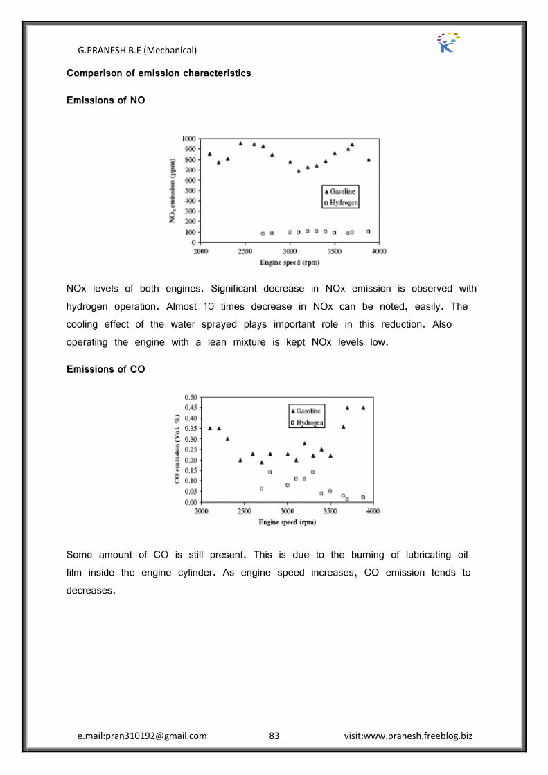
G.PRANESH B.E (Mechanical)
e.mail:[email protected] 83 visit:www.pranesh.freeblog.biz
Comparison of emission characteristics
Emissions of NO
NOx levels of both engines. Significant decrease in NOx emission is observed with hydrogen operation. Almost 10 times decrease in NOx can be noted, easily. The cooling effect of the water sprayed plays important role in this reduction. Also operating the engine with a lean mixture is kept NOx levels low.
Emissions of CO
Some amount of CO is still present. This is due to the burning of lubricating oil film inside the engine cylinder. As engine speed increases, CO emission tends to decreases.

G.PRANESH B.E (Mechanical)
e.mail:[email protected] 84 visit:www.pranesh.freeblog.biz
Emissions of HC
The temperature caused by combustion is very high inside the cylinder. As the piston expends the heat evaporates some amount of oil. In addition to this evaporated oil, incompletely burned oil also contributes to HC emission.
Comparison of combustion characteristics
Short time of combustion produces lower exhaust gas temperature for hydrogen. Hydrogen is a very good candidate as an engine fuel. Appropriate changes in the combustion chamber together with better cooling mechanism would increase the possibility of using hydrogen across a wider operating range.
G.PRANESH B.E (Mechanical)
e.mail:[email protected] 85 visit:www.pranesh.freeblog.biz
UNIT V RECENT TRENDS
2 MARK QUESTION AND ANSWER
1. What is lean burn engine?
Lean burn engine is a lay out of Otto cycle engine designed to permit the combustion of lean air fuel mixture and to obtain simultaneously low emission values as high fuel economy. It is designed to operate effectively in the air fuel ratio 14:1-16:1to 20:1-22:1. When the lean compression ratio, combustion chamber shape, ignition system, the lean limit are successfully optimized, the engine is refused to as a lean burn engine.
2. Why lean mixture is preferred in SI engine?
Lean mixture is preferred in SI engine because of the following facts:
Lower pollutants. Good fuel economy. Heat transfer losses to the cooing medium are reduced because of lower
peak temperatures. Since lean mixture are less prove to knocking.
3. What are the modifications to be made to convert an existing engine as a lean burn engine?
The modifications to be made to comments an existing engine as a lean burn engine are:
Increasing the compression ratio of the engine to accurate flame propagation. Increasing the swirl and turbulence of the mixture in order to increase flame
speed. Catalytic activation of the charge in the combustion chamber.
G.PRANESH B.E (Mechanical)
e.mail:[email protected] 86 visit:www.pranesh.freeblog.biz
4. How the stratified charge engine can be characterised?
The stratified charge engine can be characterised by the following features:
Relatively high compression ratio Ability of direct cylinder fuel injection variations to run unthrottled. Stratification of the charge mixture into distinctly different rich and lean air
fuel ratios.
5. List the advantages of the stratified charge engine.
The advantages of the stratified charge engines are:
Low octane fuels (cheaper fuels) can be used at higher compression ratios.
Load control can be achieved without air throttling Quiet in operation. Multi fuels give more or less equal performance.
6. What are the main disadvantages of the stratified charge engine?
The main disadvantages of the stratified charge engines are:
Maximum output (from the air in the cylinder (i.e.) complete utilization of air) is not achieved.
The added cost of the injection/modified combustion systems. Added complication of injection and spark ignition systems.
7. Write short notes on plasma jet ignition system.
The plasma jet ignition system uses a plasma jet spark plug. This system can be considered as a form of electrical torch ignition, since the ignition source is hot jet plasma which project well away from the spark plug. The plasma jet ignition sources is turbulent and electrode less, both desirable features for igniting marginal mixtures.
G.PRANESH B.E (Mechanical)
e.mail:[email protected] 87 visit:www.pranesh.freeblog.biz
8. What are the factors that influence the operation of the plasma jet plug?
The factors that can influence the operation of the plasma jet plug are the amount of the applied electrical energy, the rate of energy delivery, the cavity volume, the cavity dimensions, the orifice size, the ambient gas pressure and the quantity of fuel present in the cavity.
9. What are the reasons for automotive engines equipped with gasoline injection system?
Some of the recent automotive engines are equipped with gasoline injection system, instead of a carburetion for the reasons:
To have uniform distribution of fuel in a multi cylinder engine. To improve breathing capacity (i.e.) volumetric efficiency. To reduce or eliminate detonation.
10. What are the types of injection systems?
Gasoline Direct Injection (GDI) in to the cylinder Port injection (a) timed (b) continuous Manifold injection
11. What are the objectives of the fuel injection system?
The objectives of the fuel injection system are to meter, atomize and uniformly distribute the fuel throughout the air mass in the cylinder.
12. What are the components of injection system?
The components of injection system are:
Pumping element Metering element Mixing element Mixture control Timing control
G.PRANESH B.E (Mechanical)
e.mail:[email protected] 88 visit:www.pranesh.freeblog.biz
13. Write notes on continuous injection system.
Continuous injection system usually has a rotary pump. The pump maintains the fuel line gauge pressure of about 0.75 to 1.5 bars. The system injects the fuel through a nozzle located in manifold immediately downstream of the throttle plate.
14. Explain the functions of the following components.
(a) Pumping element, (b) Metering element, (c) Timing control, (d) Ambient control.
(a)Pumping element- moves the fuel from the fuel tank to the injector. This include necessary piping, filter etc.
(b)Metering element- measures and supplies the fuel at the rate demanded by load and speed conditions of the engine.
(c)Timing control- fixes the start and stop of the fuel-air mixing process.
(d)Ambient control-compensates for charges in temperature and pressure of either air or fuel that may affect the various elements of the system.
15. Write the advantages of homogeneous charge compression ignition engine?
1. Lower NOx and particulate emissions 2. High thermal efficiency
16. What are the fuels used in HCCI engines?
Diesel, gasoline, methanol, natural gas and hydrogen
17. List the disadvantages of homogeneous charge compression ignition engine?
The major problem is controlling the ignition timing over a wide lead and speed.
Power density is limited by combustion noise and high peak pressure.

G.PRANESH B.E (Mechanical)
e.mail:[email protected] 89 visit:www.pranesh.freeblog.biz
16 MARK QUESTION AND ANSWER
Homogeneous charge compression ignition Engine
Homogeneous charge compression ignition (HCCI) is a form of internal combustion in which well-mixed fuel and oxidizer (typically air) are compressed to the point of auto-ignition. As in other forms of combustion, this exothermic reaction releases chemical energy into a sensible form that can be transformed in an engine into work and heat.
Operation
Methods
A mixture of fuel and air will ignite when the concentration and temperature of reactants is sufficiently high. The concentration and/or temperature can be increased by several different ways: Methods
1. High compression ratio
2. Pre-heating of induction gases
3. Forced induction
4. Retained or re-inducted exhaust gases
Once ignited, combustion occurs very quickly. When auto-ignition occurs too early or with too much chemical energy, combustion is too fast and high in-cylinder pressures can destroy an engine. For this reason, HCCI is typically operated at lean overall fuel mixtures
In an HCCI engine (which is based on the four-stroke Otto cycle), fuel delivery control is of paramount importance in controlling the combustion process. On the intake stroke, fuel is injected into each cylinder's combustion chamber via fuel injectors mounted directly in the cylinder head. This is achieved independently from air induction which takes place through the intake plenum. By the end of the intake stroke, fuel and air have been fully introduced and mixed in the cylinder's combustion chamber.
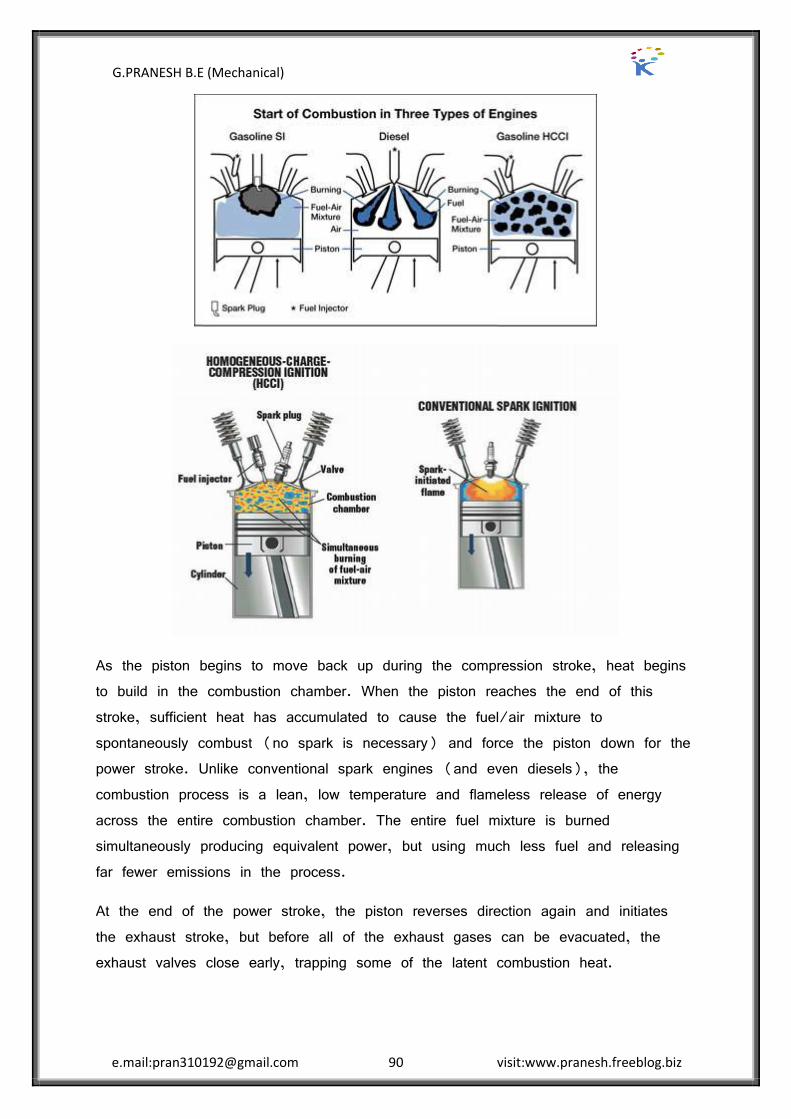
G.PRANESH B.E (Mechanical)
e.mail:[email protected] 90 visit:www.pranesh.freeblog.biz
As the piston begins to move back up during the compression stroke, heat begins to build in the combustion chamber. When the piston reaches the end of this stroke, sufficient heat has accumulated to cause the fuel/air mixture to spontaneously combust (no spark is necessary) and force the piston down for the power stroke. Unlike conventional spark engines (and even diesels), the combustion process is a lean, low temperature and flameless release of energy across the entire combustion chamber. The entire fuel mixture is burned simultaneously producing equivalent power, but using much less fuel and releasing far fewer emissions in the process.
At the end of the power stroke, the piston reverses direction again and initiates the exhaust stroke, but before all of the exhaust gases can be evacuated, the exhaust valves close early, trapping some of the latent combustion heat.
G.PRANESH B.E (Mechanical)
e.mail:[email protected] 91 visit:www.pranesh.freeblog.biz
This heat is preserved, and a small quantity of fuel is injected into the combustion chamber for a pre-charge (to help control combustion temperatures and emissions) before the next intake stroke begins.
Advantages
HCCI provides up to a 30-percent fuel savings, while meeting current emissions standards.
Since HCCI engines are fuel-lean, they can operate at a Diesel-like compression ratios (>15), thus achieving higher efficiencies than conventional spark-ignited gasoline engines.
Homogeneous mixing of fuel and air leads to cleaner combustion and lower emissions. Actually, because peak temperatures are significantly lower than in typical spark ignited engines, NOxlevels are almost negligible. Additionally, the premixed lean mixture does not produce soot.
HCCI engines can operate on gasoline, diesel fuel, and most alternative fuels.
In regards to gasoline engines, the omission of throttle losses improves HCCI efficiency.
Disadvantages
High in-cylinder peak pressures may cause damage to the engine. High heat release and pressure rise rates contribute to engine wear. The auto ignition event is difficult to control, unlike the ignition event
in spark ignition (SI) and diesel engines which are controlled by spark plugs and in-cylinder fuel injectors, respectively.
HCCI engines have a small power range, constrained at low loads by lean flammability limits and high loads by in-cylinder pressure restrictions.
Carbon monoxide (CO) and hydrocarbon (HC) pre-catalyst emissions are higher than a typical spark ignition engine, caused by incomplete oxidation (due to the rapid combustion event and low in-cylinder temperatures) and trapped crevice gases, respectively.

G.PRANESH B.E (Mechanical)
e.mail:[email protected] 92 visit:www.pranesh.freeblog.biz
Lean Burn Engine
Lean-burn means pretty much what it says. It is a lean amount of fuel supplied to and burned in an engine's combustion chamber. Normal air-to-fuel ratio is on the order of 15:1 (15 parts air to 1 part fuel). True lean-burn can go as high as 23:1.
Lean-burn engines (both gasoline and diesel) enjoy higher fuel economy and cleaner emissions than conventionally tuned engines. By nature they use less fuel and emit fewer unburned hydrocarbons and greenhouse gases while producing equivalent power of a like-sized "normal" combustion engine. They achieve lean-burn status by employing higher combustion chamber compression ratios (higher cylinder pressure), significant air intake swirl and precise lean-metered direct fuel injection.
Working Principle:

G.PRANESH B.E (Mechanical)
e.mail:[email protected] 93 visit:www.pranesh.freeblog.biz
A lean burn mode is a way to reduce throttling losses. An engine in a typical vehicle is sized for providing the power desired for
acceleration, but must operate well below that point in normal steady-speed operation. Ordinarily, the power is cut by partially closing a throttle.
However, the extra work done in pumping air through the throttle reduces efficiency.
If the fuel/air ratio is reduced, then lower power can be achieved with the throttle closer to fully open, and the efficiency during normal driving (below the maximum torque capability of the engine) can be higher.
The engines designed for lean burning can employ higher compression ratios and thus provide better performance, efficient fuel use and low exhaust hydrocarbon emissions than those found in conventional petrol engines.
Ultra lean mixtures with very high air-fuel ratios can only be achieved by direct injection engines.
The main drawback of lean burning is that a complex catalytic converter system is required to reduce NOx emissions.
Lean burn engines do not work well with modern 3-way catalytic converter which requires a pollutant balance at the exhaust port so they can carry out oxidation and reduction reactions so most modern engines run at or near the stoichiometric point.
Alternatively, ultra-lean ratios can reduce NOx emissions.
Advantages of lean burn engine
Higher fuel economy Emit fewer unburned hydrocarbons and greenhouse gases
A lean burn mode is a way to reduce throttling losses
Disadvantages of lean burn engine
Lean burning is that a complex catalytic converter system is required to reduce NOx emissions.
High relatively cost
G.PRANESH B.E (Mechanical)
e.mail:[email protected] 94 visit:www.pranesh.freeblog.biz
Stratified charge engine
An internal-combustion engine with a divided ignition cylinder that uses the ignition of rich fuel in a small chamber near the spark plug to improve the combustion of a very lean mixture throughout the rest of the cylinder.
The stratified charge engine is a type of internal-combustion engine which runs on gasoline. It is very much similar to the Diesel cycle. The name refers to the layering of the charge inside the cylinder. The stratified charge engine is designed to reduce the emissions from the engine cylinder without the use of exhaust gas recirculation systems, which is also known as the EGR or catalytic converters.
Stratified charge combustion engines utilize a method of distributing fuel that successively builds layers of fuel in the combustion chamber. The initial charge of fuel is directly injected into a small concentrated area of the combustion chamber where it ignites quickly.
Principle:-
The principle of the stratified charge engine is to deliver a mixture that is sufficiently rich for combustion in the immediate vicinity of the spark plug and in the remainder of the cylinder, a very lean mixture that is so low in fuel that it could not be used in a traditional engine. On an engine with stratified charge, the delivered power is no longer controlled by the quantity of admitted air, but by the quantity of petrol injected, as with a diesel engine.
Working:
One approach consists in dividing the combustion chamber so as to create a pre-combustion chamber where the spark plug is located. The head of the piston is also modified.
It contains a spheroid cavity that imparts a swirling movement to the air contained by the cylinder during compression. As a result, during injection, the fuel is only sprayed in the vicinity of the spark plug. But other strategies are possible.
For example, it is also possible to exploit the shape of the admission circuit and use artifices, like ‚swirl‛ or ‚tumble‛ stages that create turbulent flows at their level. All the subtlety of engine operation in stratified mode occurs at level of injection.

G.PRANESH B.E (Mechanical)
e.mail:[email protected] 95 visit:www.pranesh.freeblog.biz
This comprises two principal modes: a lean mode, which corresponds to
operation at very low engine load, therefore when there is less call on it, and a ‚normal‛ mode, when it runs at full charge and delivers maximum power.
In the first mode, injection takes place at the end of the compression stroke. Because of the swirl effect that the piston cavity creates, the fuel sprayed by the injector is confined near the spark plug. As there is very high pressure in the cylinder at this moment, the injector spray is also quite concentrated.
The ‚directivity‛ of the spray encourages even greater concentration of the mixture.
A very small quantity of fuel is thus enough to obtain optimum mixture richness in the zone close to the spark plug, whereas the remainder of the cylinder contains only very lean mixture.
The stratification of air in the cylinder means that even with partial charge it is also possible to obtain a core of mixture surrounded by layers of air and residual gases which limit the transfer of heat to the cylinder walls.
This drop in temperature causes the quantity of air in the cylinder to increase by reducing its dilation, delivering the engine additional power.
When idling, this process makes it possible to reduce consumption by almost 40% compared to a traditional engine. And this is not the only gain. Functioning with stratified charge also makes it possible to lower the temperature at which the fuel is sprayed.
All this leads to a reduction in fuel consumption which is of course reflected by a reduction of engine exhaust emissions. When engine power is required, injection takes place in normal mode, during the admission phase.
This makes it possible to achieve a homogeneous mix, as it is the case with traditional injection.

G.PRANESH B.E (Mechanical)
e.mail:[email protected] 96 visit:www.pranesh.freeblog.biz
Here, contrary to the previous example, when the injection takes place, the pressure in the cylinder is still low.
The spray of fuel from the injector is therefore highly divergent, which encourages a homogeneous mix to form.
Advantages Of Stratified Charge Engine
Compact, lightweight design &good fuel economy. Good part load efficiency. Exhibit multi fuel capability. The rich mixture near spark-plug &lean mixture near the piston surface
provides Cushing to the exploit combustion. Resist the knocking & provides smooth resulting in smooth & quite engine
operation over the entire speed & load range. Low level of exhaust emissions, Nox is reduced considerably. Usually no starting problem. Can be manufactured by the existing technology.
Disadvatages
For a given engine size, charge charge stratification results in reduced. These engines create high noise level at low load conditions. More complex design to supply rich & lean mixture & quantity is varied
with load on the engine. Higher weight than of a conventional engine. Unthrotlled stratified charge emits high percentage of HC due to either
incomplete combustion of lean charge or occasional misfire of the charge at low load conditions.
Reliability is yet to be well established. Higher manufacturing cost.
G.PRANESH B.E (Mechanical)
e.mail:[email protected] 97 visit:www.pranesh.freeblog.biz
Surface ignition engine (Hot bulb engine)
The initiation of a flame in the combustion chamber of an automobile engine by any hot surface other than the spark discharge.
The hot bulb engine, or hot bulb or heavy oil engine is a type of internal combustion engine. It is an engine in which fuel is ignited by being brought into contact with a red-hot metal surface inside a bulb followed by the introduction of air (oxygen) compressed into the hot bulb chamber by the rising piston. There is some ignition when the fuel is introduced but it quickly uses up the available oxygen in the bulb. Vigorous ignition takes place only when sufficient oxygen is supplied to the hot bulb chamber on the compression stroke of the engine.
Most hot bulb engines were produced as one-cylinder low-speed two-stroke crankcase scavenging units.
Operation and working cycle
The hot-bulb engine shares its basic layout with nearly all other internal combustion engines, in that it has a piston, inside a cylinder, connected to a flywheel via a connecting rod and crankshaft. The flow of gases through the engine is controlled by valves in four-stroke engines, and by the piston covering and uncovering ports in the cylinder wall in two-strokes. The type of blow-lamp used to start the Hot Bulb engine.
In the hot-bulb engine combustion takes place in a separated combustion chamber, the "vaporizer" (also called the "hot bulb"), usually mounted on the cylinder head, into which fuel is sprayed. It is connected to the cylinder by a narrow passage and is heated by the combustion while running; an external flame such as a blow-lamp or slow-burning wick is used for starting (on later models sometimes electric heating or pyrotechnics was used). Another method is the inclusion of a spark plug and vibrator coil ignition.[citation needed] The engine could be started on petrol and switched over to oil after it had warmed to running temperature.
The pre-heating time depends on the engine design, the type of heating used and the ambient temperature, but generally ranges from 2”5 minutes (for most engines in a temperate climate) to as much as half an hour (if operating in extreme cold or the engine is especially large). The engine is then turned over, usually by hand but sometimes by compressed air or an electric motor.
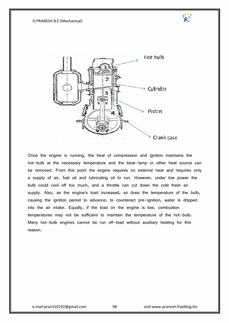
G.PRANESH B.E (Mechanical)
e.mail:[email protected] 98 visit:www.pranesh.freeblog.biz
Once the engine is running, the heat of compression and ignition maintains the hot-bulb at the necessary temperature and the blow-lamp or other heat source can be removed. From this point the engine requires no external heat and requires only a supply of air, fuel oil and lubricating oil to run. However, under low power the bulb could cool off too much, and a throttle can cut down the cold fresh air supply. Also, as the engine's load increased, so does the temperature of the bulb, causing the ignition period to advance; to counteract pre-ignition, water is dripped into the air intake. Equally, if the load on the engine is low, combustion temperatures may not be sufficient to maintain the temperature of the hot-bulb. Many hot-bulb engines cannot be run off-load without auxiliary heating for this reason.

G.PRANESH B.E (Mechanical)
e.mail:[email protected] 99 visit:www.pranesh.freeblog.biz
Four Valve and Overhead cam Engines
Four Valve Engine:
A multi-valve design typically has three, four, or five valves per cylinder to achieve improved performance. Any four-stroke internal combustion engine needs at least two valves per cylinder: one for intake of air and fuel, and another for exhaust of combustion gases. Adding more valves increases valve area and improves the flow of intake and exhaust gases, thereby enhancing combustion, volumetric efficiency, and power output. Multi-valve geometry allows the spark plug to be ideally located within the combustion chamber for optimal flame propagation. Multi-valve engines tend to have smaller valves that have lower reciprocating mass, which can reduce wear on each cam lobe, and allow more power from higher RPM without the danger of valve bounce.
Four-valve cylinder head
This is the most common type of multi-valve head, with two exhaust valves and two similar (or slightly larger) inlet valves. This design allows similar breathing as compared to a three-valve head, and as the small exhaust valves allow high RPM, this design is very suitable for high power outputs.
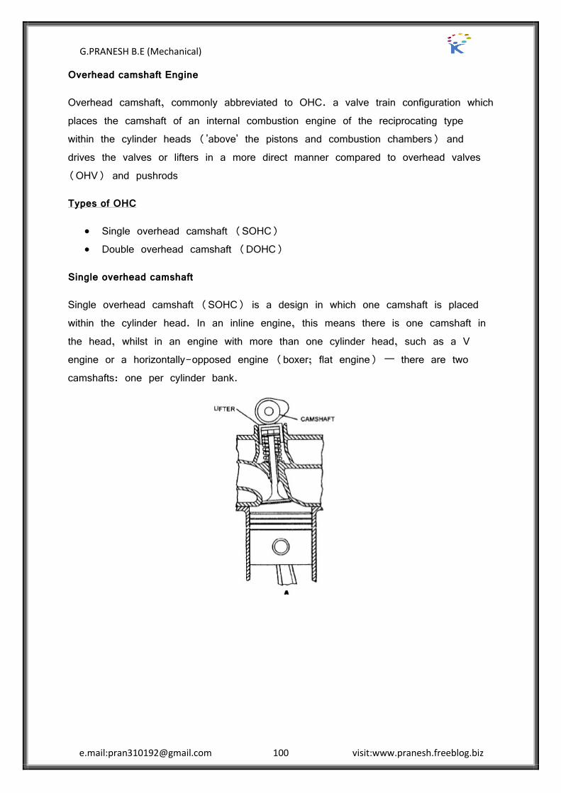
G.PRANESH B.E (Mechanical)
e.mail:[email protected] 100 visit:www.pranesh.freeblog.biz
Overhead camshaft Engine
Overhead camshaft, commonly abbreviated to OHC. a valve train configuration which places the camshaft of an internal combustion engine of the reciprocating type within the cylinder heads ('above' the pistons and combustion chambers) and drives the valves or lifters in a more direct manner compared to overhead valves (OHV) and pushrods
Types of OHC
Single overhead camshaft (SOHC) Double overhead camshaft (DOHC)
Single overhead camshaft
Single overhead camshaft (SOHC) is a design in which one camshaft is placed within the cylinder head. In an inline engine, this means there is one camshaft in the head, whilst in an engine with more than one cylinder head, such as a V engine or a horizontally-opposed engine (boxer; flat engine) „ there are two camshafts: one per cylinder bank.
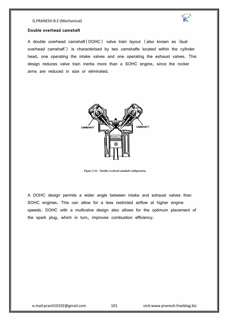
G.PRANESH B.E (Mechanical)
e.mail:[email protected] 101 visit:www.pranesh.freeblog.biz
Double overhead camshaft
A double overhead camshaft(DOHC) valve train layout (also known as 'dual overhead camshaft') is characterised by two camshafts located within the cylinder head, one operating the intake valves and one operating the exhaust valves. This design reduces valve train inertia more than a SOHC engine, since the rocker arms are reduced in size or eliminated.
A DOHC design permits a wider angle between intake and exhaust valves than SOHC engines. This can allow for a less restricted airflow at higher engine speeds. DOHC with a multivalve design also allows for the optimum placement of the spark plug, which in turn, improves combustion efficiency.
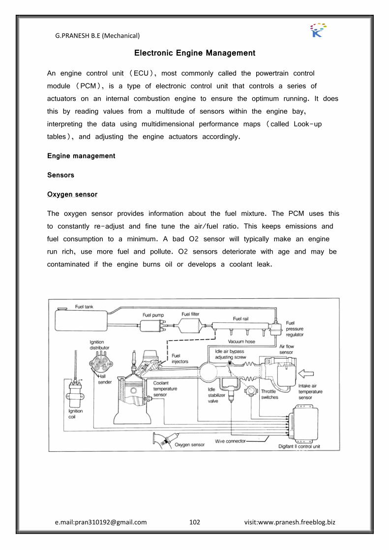
G.PRANESH B.E (Mechanical)
e.mail:[email protected] 102 visit:www.pranesh.freeblog.biz
Electronic Engine Management
An engine control unit (ECU), most commonly called the powertrain control module (PCM), is a type of electronic control unit that controls a series of actuators on an internal combustion engine to ensure the optimum running. It does this by reading values from a multitude of sensors within the engine bay, interpreting the data using multidimensional performance maps (called Look-up tables), and adjusting the engine actuators accordingly.
Engine management
Sensors
Oxygen sensor
The oxygen sensor provides information about the fuel mixture. The PCM uses this to constantly re-adjust and fine tune the air/fuel ratio. This keeps emissions and fuel consumption to a minimum. A bad O2 sensor will typically make an engine run rich, use more fuel and pollute. O2 sensors deteriorate with age and may be contaminated if the engine burns oil or develops a coolant leak.

G.PRANESH B.E (Mechanical)
e.mail:[email protected] 103 visit:www.pranesh.freeblog.biz
Coolant sensor
The coolant sensor monitors engine temperature. The PCM uses this information to regulate a wide variety of ignition, fuel and emission control functions. When the engine is cold, for example, the fuel mixture needs to be richer to improve drivability. Once the engine reaches a certain temperature, the PCM starts using the signal from the O2 sensor to vary the fuel mixture. This is called "closed loop" operation, and it is necessary to keep emissions to a minimum.
Throttle position sensor (TPS)
The throttle position sensor (TPS) keeps the PCM informed about throttle position. The PCM uses this input to change spark timing and the fuel mixture as engine load changes. A problem here can cause a flat spot during acceleration (like a bad accelerator pump in a carburetor) as well as other drivability complaints.
Airflow Sensor
The Airflow Sensor, of which there are several types, tells the PCM how much air the engine is drawing in as it runs. The PCM uses this to further vary the fuel mixture as needed. There are several types of airflow sensors including hot wire mass airflow sensors and the older flap-style vane airflow sensors. All are very expensive to replace
Manifold absolute pressure (MAP)
The manifold absolute pressure (MAP) sensor measures intake vacuum, which the PCM also uses to determine engine load. The MAP sensor's input affects ignition timing primarily, but also fuel delivery.
Knock sensors
Knock sensors are used to detect vibrations produced by detonation. When the PCM receives a signal from the knock sensor, it momentarily retards timing while the engine is under load to protect the engine against spark knock.
EGR position sensor
The EGR position sensor tells the PCM when the exhaust gas recirculation (EGR) valve opens (and how much). This allows the PCM to detect problems with the EGR system that would increase pollution.

G.PRANESH B.E (Mechanical)
e.mail:[email protected] 104 visit:www.pranesh.freeblog.biz
Vehicle speed sensor (VSS)
The vehicle speed sensor (VSS) keeps the PCM informed about how fast the vehicle is traveling. This is needed to control other functions such as torque converter lockup. The VSS signal is also used by other control modules, including the antilock brake system (ABS).
Crankshaft position sensor
The crankshaft position sensor serves the same function as the pickup assembly in an engine with a distributor. It does two things: It monitors engine rpm and helps the computer determine relative position of the crankshaft so the PCM can control spark timing and fuel delivery in the proper sequence. The PCM also uses the crank sensor's input to regulate idle speed, which it does by sending a signal to an idle speed control motor or idle air bypass motor. On some engines, an additional camshaft position sensor is used to provide additional input to the PCM about valve timing.

G.PRANESH B.E (Mechanical)
e.mail:[email protected] 105 visit:www.pranesh.freeblog.biz
Common Rail Direct Injection Diesel Engine
Common rail direct fuel injection is a modern variant of direct fuel injection system for petrol and diesel engines.
A diesel fuel injection system employing a common pressure accumulator, called the rail, which is mounted along the engine block.
The rail is fed by a high pressure fuel pump. The injectors, which are fed from the common rail, are activated by solenoid valves.
The solenoid valves and the fuel pump are electronically controlled. In the common rail injection system the injection pressure is independent from engine speed and load. Therefore, the injection parameters can be freely controlled.
Usually a pilot injection is introduced, which allows for reductions in engine noise and NOx emissions. This system operates at 27,500 psi (1900 BAR).
The injectors use a needle-and seat-type valve to control fuel flow and fuel pressure is fed to both the top and bottom of the needle valve.
By bleeding some of the pressure off the top, the pressure on the bottom will push the needle off its seat and fuel will flow through the nozzle holes.
G.PRANESH B.E (Mechanical)
e.mail:[email protected] 106 visit:www.pranesh.freeblog.biz
Gasoline Direct Injection (GDI)
In internal combustion engines, Gasoline Direct Injection (GDI), also known as Petrol Direct Injection or Direct Petrol Injection or Spark Ignited Direct Injection (SIDI) or Fuel Stratified Injection (FSI), is a variant of fuel injection employed in modern two-stroke and four-stroke gasoline engines. The gasoline is highly pressurized, and injected via a common rail fuel line directly into the combustion chamber of each cylinder, as opposed to conventional multi-point fuel injection that happens in the intake tract, or cylinder port.
Operation
The major advantages of a GDI engine are increased fuel efficiency and high power output. Emissions levels can also be more accurately controlled with the GDI system. The cited gains are achieved by the precise control over the amount of fuel and injection timings that are varied according to engine load. In addition, there are no throttling losses in some GDI engines, when compared to a conventional fuel-injected or carbureted engine, which greatly improves efficiency, and reduces 'pumping losses' in engines without a throttle plate. Engine speed is controlled by the engine control unit/engine management system (EMS), which regulates fuel injection function and ignition timing, instead of having a throttle plate that restricts the incoming air supply. Adding this function to the EMS requires considerable enhancement of its processing and memory, as direct injection plus the engine speed management must have very precise algorithms for good performance and drivability.
The engine management system continually chooses among three combustion modes: ultra-lean burn, stoichiometric, and full power output.
Ultra lean burn or stratified charge mode is used for light-load running conditions, at constant or reducing road speeds, where no acceleration is required. The fuel is not injected at the intake stroke but rather at the latter stages of the compression stroke. The combustion takes place in a cavity on the piston's surface which has a toroidal or an ovoidal shape, and is placed either in the centre (for central injector), or displaced to one side of the piston that is closer to the injector. The cavity creates the swirl effect so that the small amount of air-fuel mixture is optimally placed near the spark plug. This stratified charge is surrounded mostly by air and residual gases, which keeps the fuel and the flame away from the cylinder

G.PRANESH B.E (Mechanical)
e.mail:[email protected] 107 visit:www.pranesh.freeblog.biz
walls. Decreased combustion temperature allows for lowest emissions and heat losses and increases air quantity by reducing dilation, which delivers additional power. This technique enables the use of ultra-lean mixtures that would be impossible with carburettors or conventional fuel injection.
Stoichiometric mode is used for moderate load conditions. Fuel is injected during the intake stroke, creating a homogeneous fuel-air mixture in the cylinder. From the stoichiometric ratio, an optimum burn results in a clean exhaust emission, further cleaned by the catalytic converter.
Full power mode is used for rapid acceleration and heavy loads (as when climbing a hill). The air-fuel mixture is homogeneous and the ratio is slightly richer than stoichiometric, which helps prevent detonation (pinging). The fuel is injected during the intake stroke.
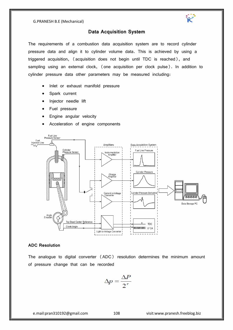
G.PRANESH B.E (Mechanical)
e.mail:[email protected] 108 visit:www.pranesh.freeblog.biz
Data Acquisition System
The requirements of a combustion data acquisition system are to record cylinder pressure data and align it to cylinder volume data. This is achieved by using a triggered acquisition, (acquisition does not begin until TDC is reached), and sampling using an external clock, (one acquisition per clock pulse). In addition to cylinder pressure data other parameters may be measured including:
Inlet or exhaust manifold pressure Spark current Injector needle lift Fuel pressure Engine angular velocity Acceleration of engine components
ADC Resolution
The analogue to digital converter (ADC) resolution determines the minimum amount of pressure change that can be recorded
G.PRANESH B.E (Mechanical)
e.mail:[email protected] 109 visit:www.pranesh.freeblog.biz
Where ΔP is the total pressure range (typically 100 bars) and r is the bit resolution of the ADC.
Triggering
In order to phase the measured data with the cylinder volume it is necessary to accurately determine at what point in the engine’s thermodynamic cycle the data acquisition started. A common method is to begin the acquisition when the crank is a TDC. This has the disadvantage that the recorded data may begin at either compression TDC or exhaust TDC. A simple check can be used to correct this by comparing data acquired at zero and 360 degrees.
External Clock
Engine rotational velocity will always vary with time due to cycle-to-cycle variability in combustion timing and strength. It is therefore not possible to acquire data with a clock frequency dependent on engine speed and still accurately align measured data with the corresponding cylinder volume. Hence an external clock is used. This provides a Phase Locked Loop (PLL) signal that indicates when a certain amount of engine rotation has occurred.
Pressure Transducers
Piezoelectric pressure transducers are the most commonly used form of pressure transducer for the purpose of acquiring in-cylinder pressure data. They however have several disadvantages, these include sensitivity to thermal shock, long and short-term drift, sensitivity to temperature and that the output has to be referenced to an absolute pressure.
Charge Amplifiers
Charge amplifier range and time constants should be set to give the longest system time with minimal signal drift. The time constant of a piezoelectric system is a measure of the time for a given signal to decay, not the time it takes the system to respond to an input. It is important that all connections between the charge amplifier and transducer be degreased with contact cleaner. This is because low insulation resistance in the transducer or cables and connection causes drift of the charge amplifier output. Charge amplifier is allowed to warm up for one hour before measurements are taken.

G.PRANESH B.E (Mechanical)
e.mail:[email protected] 110 visit:www.pranesh.freeblog.biz
Pressure pick up
The transducer for in-cylinder pressure measurement
Piezoelectric pressure transducer
The principle of operation of a piezoelectric pressure transducer. The pressure change rate (dP/dt) experienced by the transducer diaphragm is transmitted to a piezoelectric crystal through intermediate elements, causing its deformation at a rate dε/dt. Due to the piezoelectric effect, this deformation polarizes charge q in the transducer electrode originating an electric current i, which constitutes the transducer output signal:
Where Gs is the transducer sensitivity (gain).
During the measurement of in-cylinder pressure, the transducer is exposed to a transient heat flow that causes continuous changes in its temperature. These temperature changes modify the sensitivity of the piezoelectric element and impose thermal stresses in the diaphragm and in the sensor housing, generating spurious forces that act on the quartz element and cause additional distortion of the signal provided by the transducer.
----------------------------------------------------
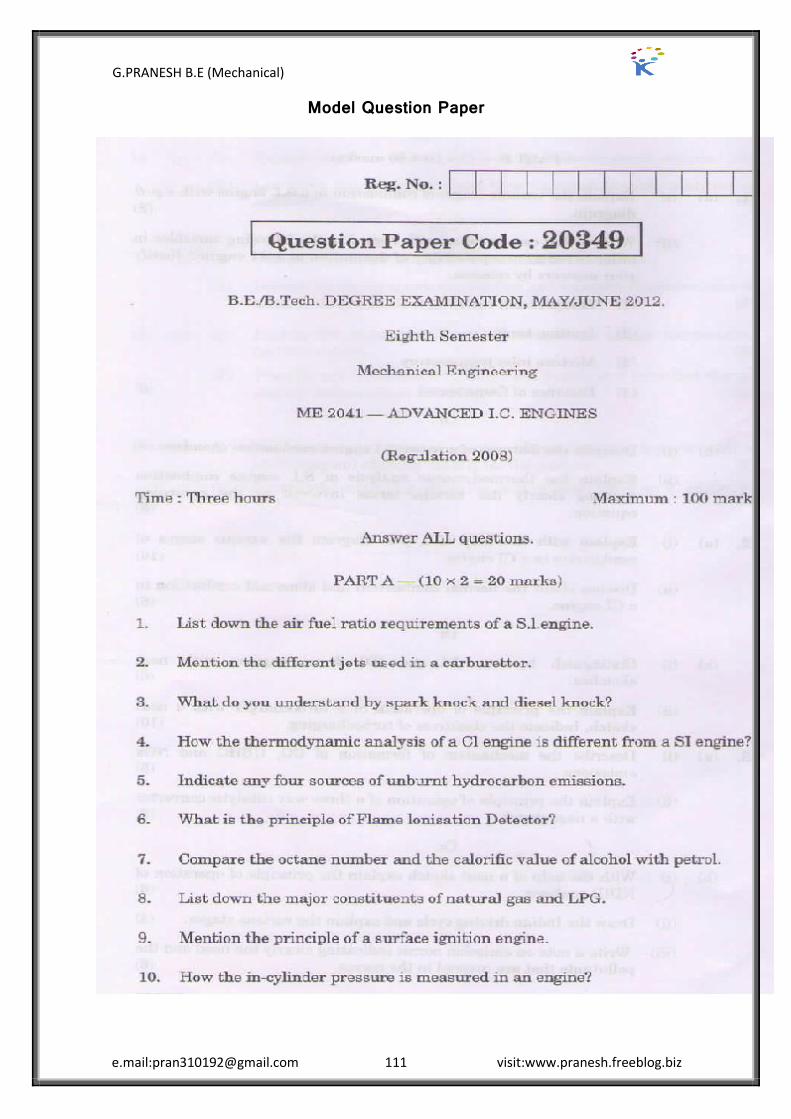
G.PRANESH B.E (Mechanical)
e.mail:[email protected] 111 visit:www.pranesh.freeblog.biz
Model Question Paper