Advanced Hydrogen-Fueled Engines: Potential and … hydrogen fueled internal combustion engines (H...
27
Advanced Hydrogen-Fueled Engines: Potential and Challenges Christopher White University of New Hampshire Sandia National Laboratories ERC Symposium: Fuels for Future Internal Combustion Engines University of Wisconsin Madison June 6, 2007 Sandia Sponsor: DOE Office of FreedomCAR and Vehicles Technologies Program Manager: Gurpreet Singh
Transcript of Advanced Hydrogen-Fueled Engines: Potential and … hydrogen fueled internal combustion engines (H...
Advanced Hydrogen-Fueled Engines: Potential and Challenges
Christopher WhiteUniversity of New Hampshire
Sandia National Laboratories
ERC Symposium: Fuels for Future Internal Combustion Engines
University of Wisconsin Madison
June 6, 2007
Sandia Sponsor: DOE Office of FreedomCAR and Vehicles Technologies
Program Manager: Gurpreet Singh
Why hydrogen fueled internal combustion engines (H2ICE).
Need for advanced H2ICEs─ relative to conventional port-fuel-injected (PFI) H2ICEs
Example advanced H2ICE strategies
Sandia National Laboratories H2 Engine Program─ objective and approach
─ brief discussion of experiments and results
Summary
Presentation outline
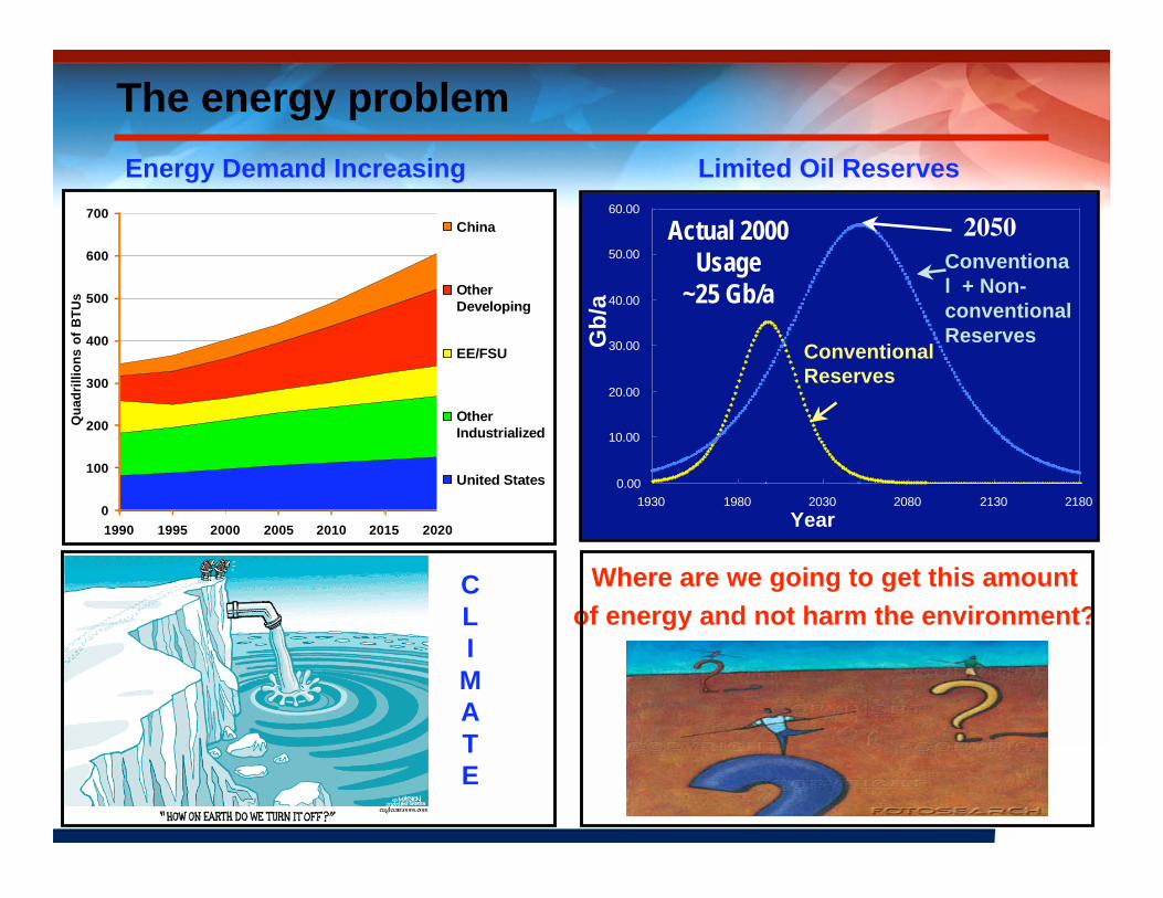
The energy problem
0
100
200
300
400
500
600
700
1990 1995 2000 2005 2010 2015 2020
Qu
ad
rill
ion
s o
f B
TU
s
China
Other
Developing
EE/FSU
Other
Industrialized
United States
Energy Demand Increasing
0.00
10.00
20.00
30.00
40.00
50.00
60.00
1930 1980 2030 2080 2130 2180
Year
Gb
/a
2050Actual 2000
Usage
~25 Gb/a
ConventionalReserves
Conventional + Non-conventionalReserves
Limited Oil Reserves
Where are we going to get this amount
of energy and not harm the environment?CLI
MATE
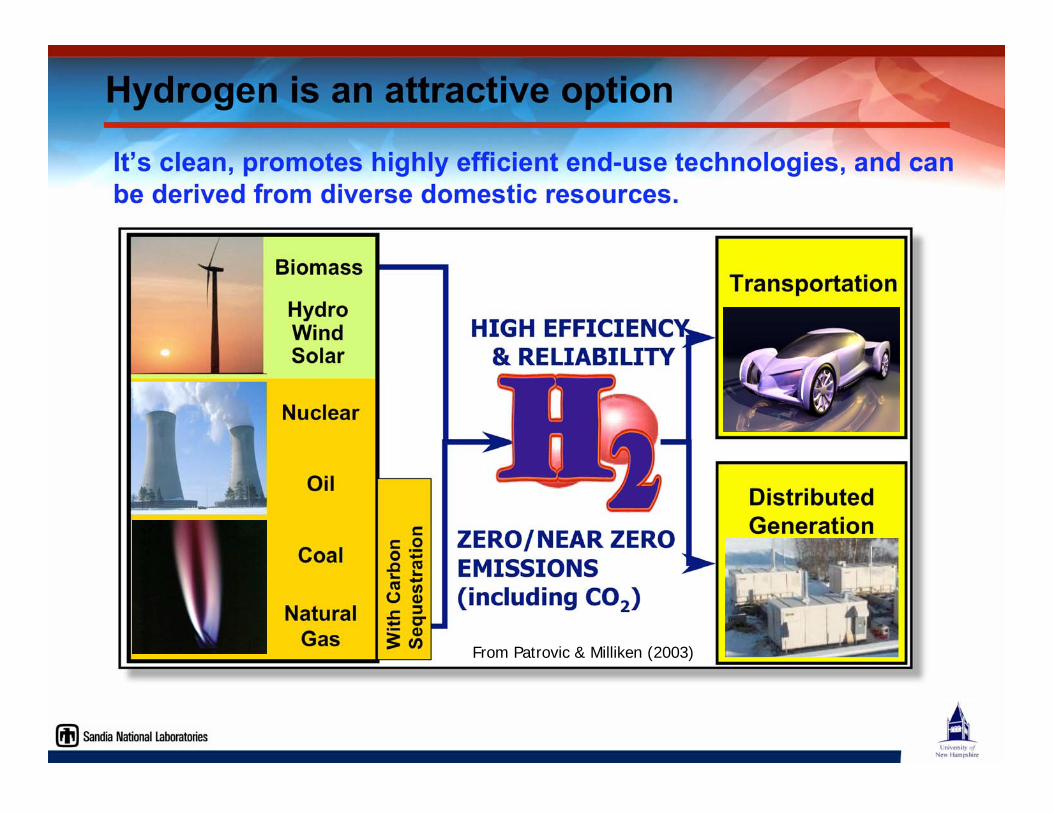
Hydrogen is an attractive option
It’s clean, promotes highly efficient end-use technologies, and canbe derived from diverse domestic resources.
.
DistributedGeneration
TransportationBiomass
HydroWindSolar
Coal
Nuclear
NaturalGas
Oil
Wit
h C
arb
on
Se
qu
es
tra
tio
n
HIGH EFFICIENCY & RELIABILITY
ZERO/NEAR ZEROEMISSIONS(including CO2)
From Patrovic & Milliken (2003)
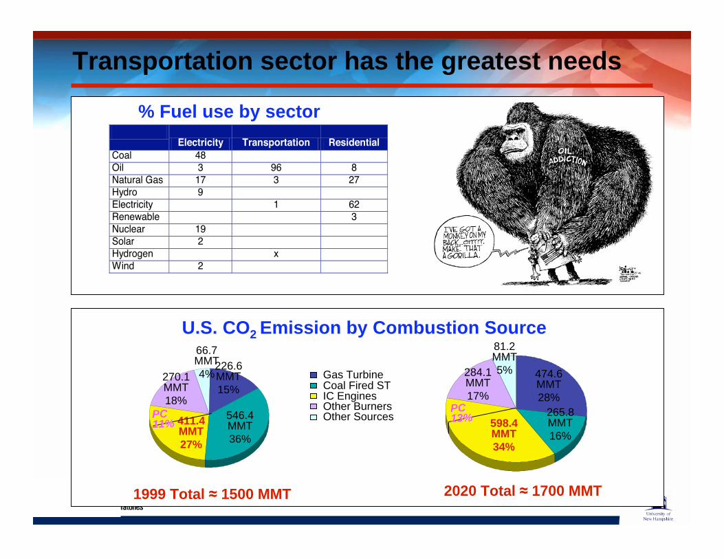
Transportation sector has the greatest needs
Electricity Transportation Residential
Coal 48 Oil 3 96 8 Natural Gas 17 3 27 Hydro 9 Electricity 1 62 Renewable 3 Nuclear 19 Solar 2 Hydrogen x Wind 2
% Fuel use by sector
1999 Total 1500 MMT
Gas TurbineCoal Fired STIC EnginesOther BurnersOther Sources546.4
MMT
36%
226.6MMT
15%270.1MMT
18%
411.4MMT27%
66.7MMT
4%
PCPC
11%11%
265.8MMT
16%
474.6MMT
28%
284.1MMT
17%
598.4MMT34%
81.2MMT
5%
PCPC
13%13%
2020 Total 1700 MMT
U.S. CO2 Emission by Combustion Source
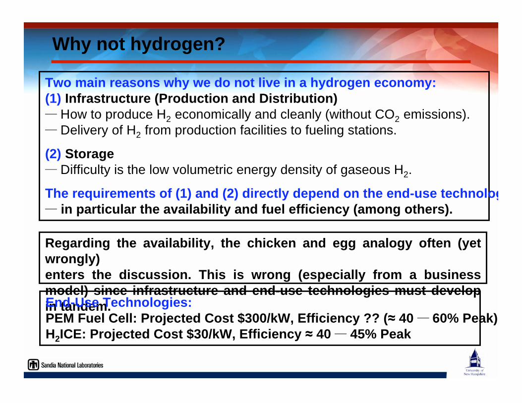
Why not hydrogen?
Two main reasons why we do not live in a hydrogen economy:(1) Infrastructure (Production and Distribution)─ How to produce H2 economically and cleanly (without CO2 emissions).
─ Delivery of H2 from production facilities to fueling stations.
(2) Storage─ Difficulty is the low volumetric energy density of gaseous H2.
The requirements of (1) and (2) directly depend on the end-use technolog─ in particular the availability and fuel efficiency (among others).
Regarding the availability, the chicken and egg analogy often (yetwrongly)enters the discussion. This is wrong (especially from a businessmodel) since infrastructure and end-use technologies must developin tandem.End-Use Technologies: PEM Fuel Cell: Projected Cost $300/kW, Efficiency ?? ( 40 ─ 60% Peak)H2ICE: Projected Cost $30/kW, Efficiency 40 ─ 45% Peak
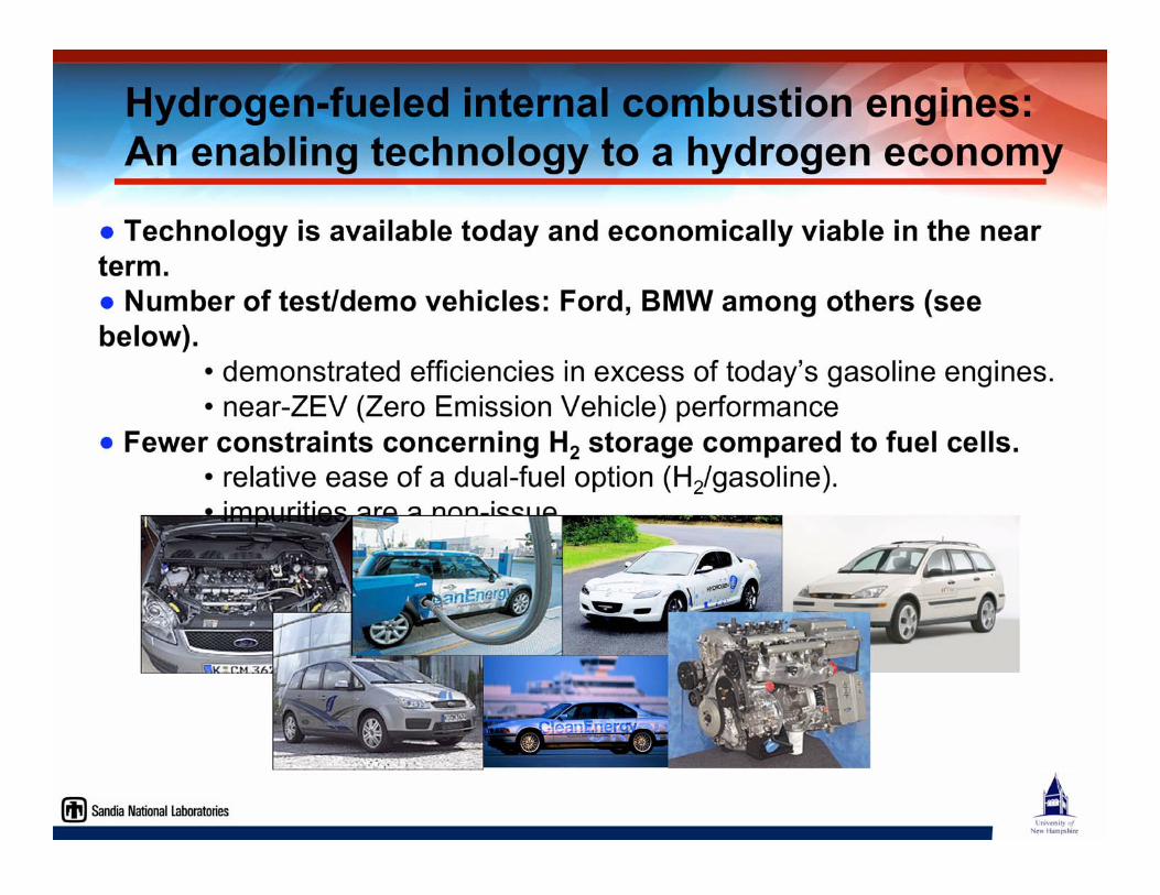
Technology is available today and economically viable in the nearterm.
Number of test/demo vehicles: Ford, BMW among others (seebelow).
• demonstrated efficiencies in excess of today’s gasoline engines.
• near-ZEV (Zero Emission Vehicle) performance
Fewer constraints concerning H2 storage compared to fuel cells.• relative ease of a dual-fuel option (H2/gasoline).
• impurities are a non-issue
Hydrogen-fueled internal combustion engines: An enabling technology to a hydrogen economy
Integral part of DOE's transitional strategy towards a hydrogen economy • www.hydrogen.energy.gov/pdfs/hydrogen_posture_plan.pdf
DOE's near-term goals for the H2ICE (same as for fuel cell vehicle): • peak brake thermal efficiency (BTE) 45%.
• Tier2/bin5 emissions or better (NOx 0.07g/mile).
• power densities greater than present-day gasoline engines.
Research is required to resolve technical barriers to meet these goals. • fundamental research of in-cylinder combustion and transport processes.
• NOx emissions and control.
• advanced H2ICE concepts and related technical issues:
DOE’s interest in H2ICEs
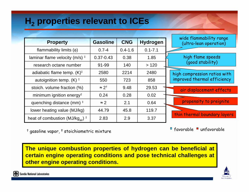
The unique combustion properties of hydrogen can be beneficial atcertain engine operating conditions and pose technical challenges atother engine operating conditions.
H2 properties relevant to ICEs
29.539.48 2†stoich. volume fraction (%)
> 12014091-99research octane number
1.850.380.37-0.43laminar flame velocity (m/s) ‡
2.9
45.8
2.1
0.28
723
2214
0.4-1.6
CNG
2.83
44.79
2
0.24
550
2580
0.7-4
Gasoline
2480adiabatic flame temp. (K)‡
0.1-7.1flammability limits ( )
3.37heat of combustion (MJ/kgair) ‡
119.7lower heating value (MJ/kg)
0.64quenching distance (mm) ‡
858autoignition temp. (K) ‡
minimum ignition energy‡
Property
0.02
Hydrogen
† gasoline vapor, ‡ stoichiometric mixture
wide flammability range(ultra-lean operation)
high flame speeds(good stability)
high compression ratios withimproved thermal efficiency
air displacement effects
propensity to preignite
thin thermal boundary layers
favorable unfavorable
0 0.5 1 1.5 2 2.5 3 3.5 410
-2
10-1
100
101
minimum ignition
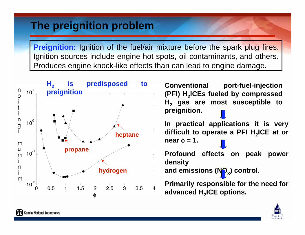
hydrogen
heptane
propane
H2 is predisposed topreignition
Preignition: Ignition of the fuel/air mixture before the spark plug fires.
Ignition sources include engine hot spots, oil contaminants, and others.
Produces engine knock-like effects than can lead to engine damage.
Conventional port-fuel-injection(PFI) H2ICEs fueled by compressedH2 gas are most susceptible topreignition.
The preignition problem
In practical applications it is verydifficult to operate a PFI H2ICE at ornear = 1.
Profound effects on peak powerdensityand emissions (NOx) control.
Primarily responsible for the need foradvanced H2ICE options.
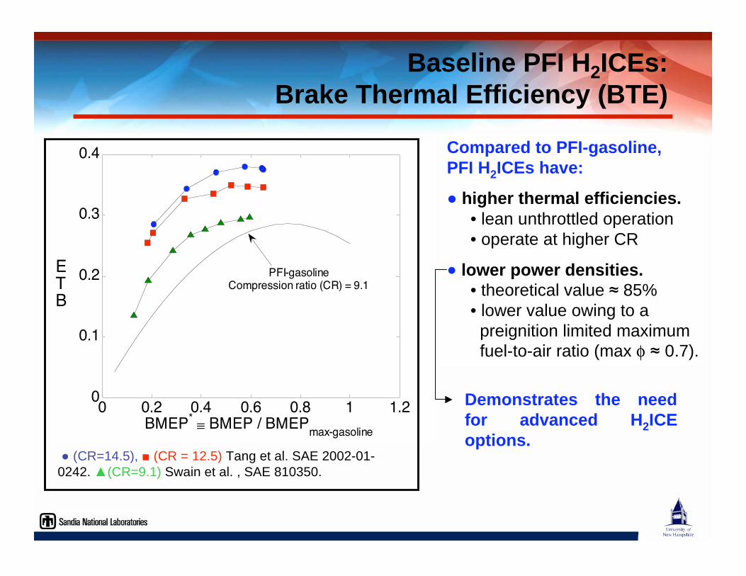
Compared to PFI-gasoline,PFI H2ICEs have:
higher thermal efficiencies. • lean unthrottled operation
• operate at higher CR
lower power densities. • theoretical value 85%
• lower value owing to a
preignition limited maximum
fuel-to-air ratio (max 0.7).
Baseline PFI H2ICEs:Brake Thermal Efficiency (BTE)
0 0.2 0.4 0.6 0.8 1 1.20
0.1
0.2
0.3
0.4
BMEP* BMEP / BMEPmax-gasoline
BTE PFI-gasoline
Compression ratio (CR) = 9.1
(CR=14.5), (CR = 12.5) Tang et al. SAE 2002-01-
0242. (CR=9.1) Swain et al. , SAE 810350.
Demonstrates the needfor advanced H2ICEoptions.
0 0.25 0.5 0.75 1 1.25 1.510
0
101
102
103
104
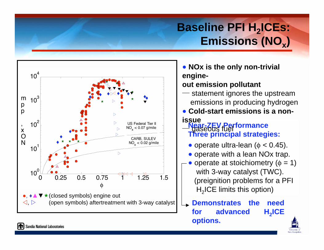
NOx, ppm
CARB, SULEV NO
x < 0.02 g/mile
US Federal Tier II NO
x < 0.07 g/mile Near-ZEV Performance
Three principal strategies:
operate ultra-lean ( < 0.45).
operate with a lean NOx trap. operate at stoichiometry ( = 1)
with 3-way catalyst (TWC).
(preignition problems for a PFI
H2ICE limits this option)
Baseline PFI H2ICEs:Emissions (NOx)
, (closed symbols) engine out
, (open symbols) aftertreatment with 3-way catalyst
NOx is the only non-trivialengine-out emission pollutant─ statement ignores the upstream
emissions in producing hydrogen
Cold-start emissions is a non-issue─ gaseous fuel
Demonstrates the needfor advanced H2ICEoptions.
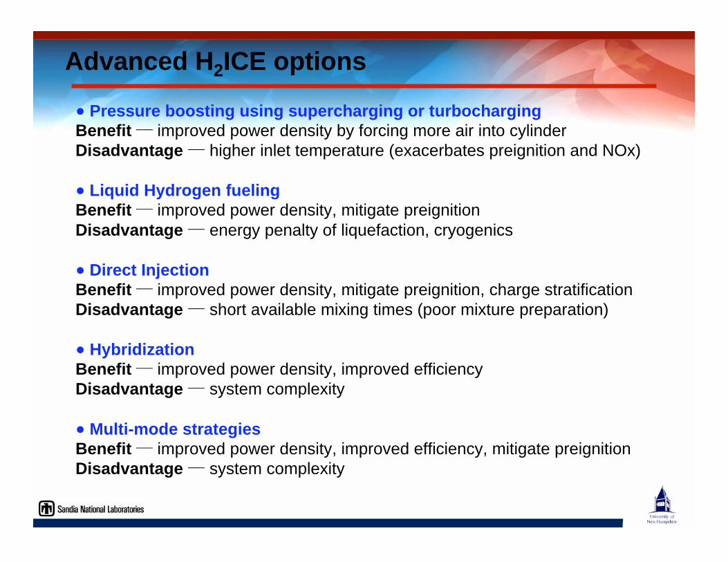
Advanced H2ICE options
Pressure boosting using supercharging or turbochargingBenefit ─ improved power density by forcing more air into cylinder
Disadvantage ─ higher inlet temperature (exacerbates preignition and NOx)
Liquid Hydrogen fuelingBenefit ─ improved power density, mitigate preignition
Disadvantage ─ energy penalty of liquefaction, cryogenics
Direct InjectionBenefit ─ improved power density, mitigate preignition, charge stratification
Disadvantage ─ short available mixing times (poor mixture preparation)
HybridizationBenefit ─ improved power density, improved efficiency
Disadvantage ─ system complexity
Multi-mode strategies
Benefit ─ improved power density, improved efficiency, mitigate preignition
Disadvantage ─ system complexity
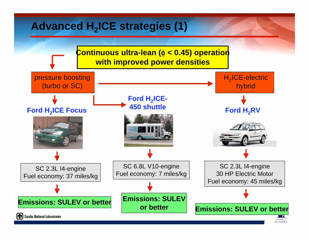
Continuous ultra-lean ( < 0.45) operationwith improved power densities
H2ICE-electric
hybrid
Ford H2RV
SC 2.3L I4-engine
30 HP Electric Motor
Fuel economy: 45 miles/kg
Emissions: SULEV or better
Ford H2ICE-450 shuttle
SC 6.8L V10-engine
Fuel economy: 7 miles/kg
Emissions: SULEVor better
pressure boosting
(turbo or SC)
SC 2.3L I4-engine
Fuel economy: 37 miles/kg
Emissions: SULEV or better
Ford H2ICE Focus
Advanced H2ICE strategies (1)
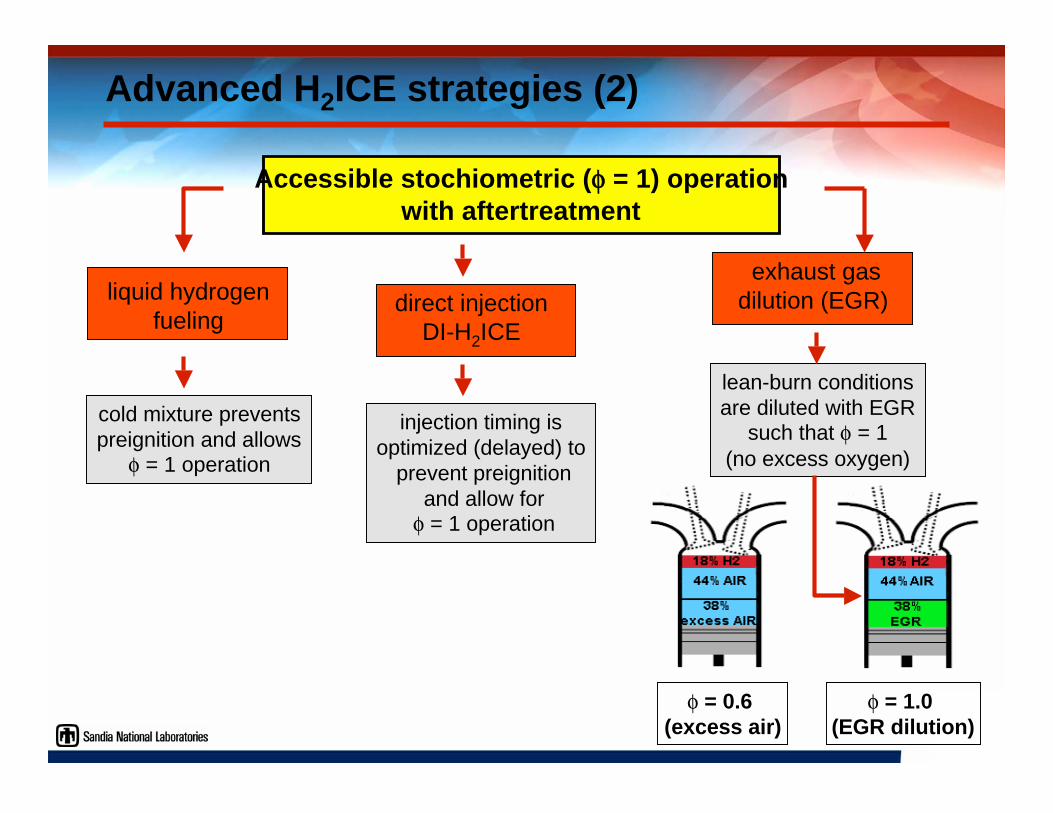
Accessible stochiometric ( = 1) operationwith aftertreatment
liquid hydrogen
fueling
cold mixture prevents
preignition and allows = 1 operation
exhaust gas
dilution (EGR)
lean-burn conditions
are diluted with EGRsuch that = 1
(no excess oxygen)
direct injection
DI-H2ICE
injection timing is
optimized (delayed) to
prevent preignition
and allow for = 1 operation
= 0.6 (excess air)
= 1.0 (EGR dilution)
Advanced H2ICE strategies (2)
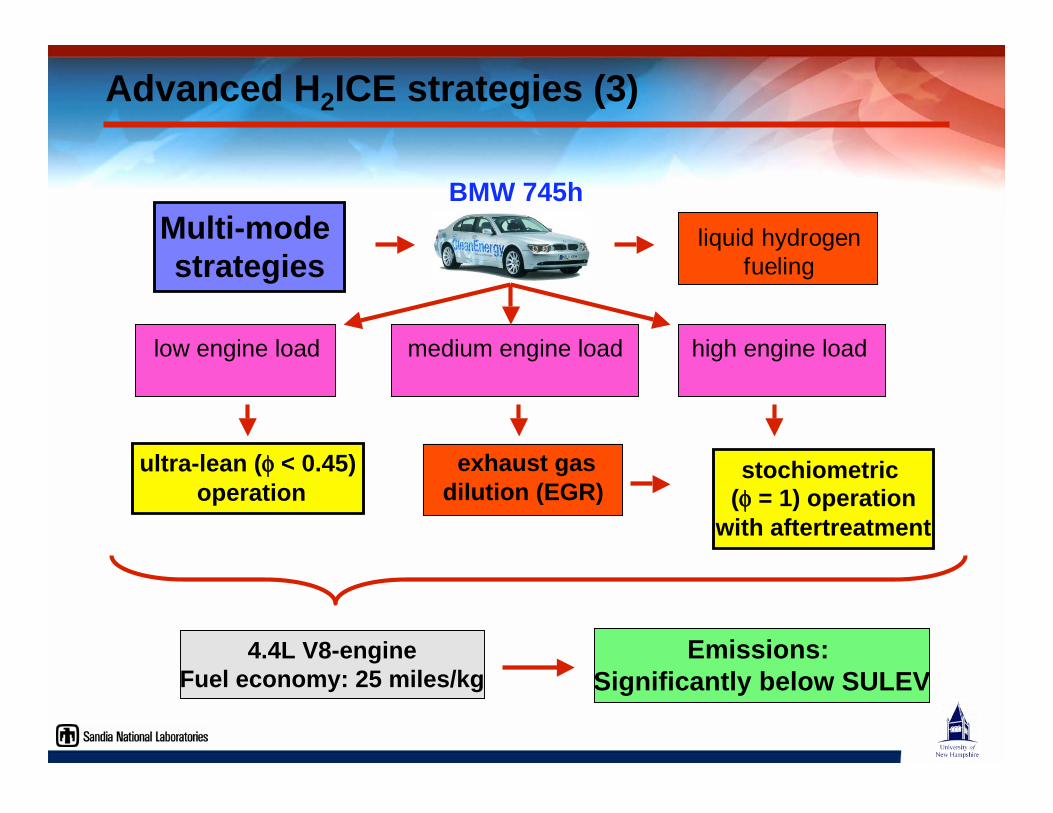
Multi-mode strategies
liquid hydrogenfueling
BMW 745h
ultra-lean ( < 0.45) operation
low engine load
stochiometric ( = 1) operation
with aftertreatment
medium engine load
exhaust gasdilution (EGR)
high engine load
4.4L V8-engineFuel economy: 25 miles/kg
Emissions: Significantly below SULEV
Advanced H2ICE strategies (3)
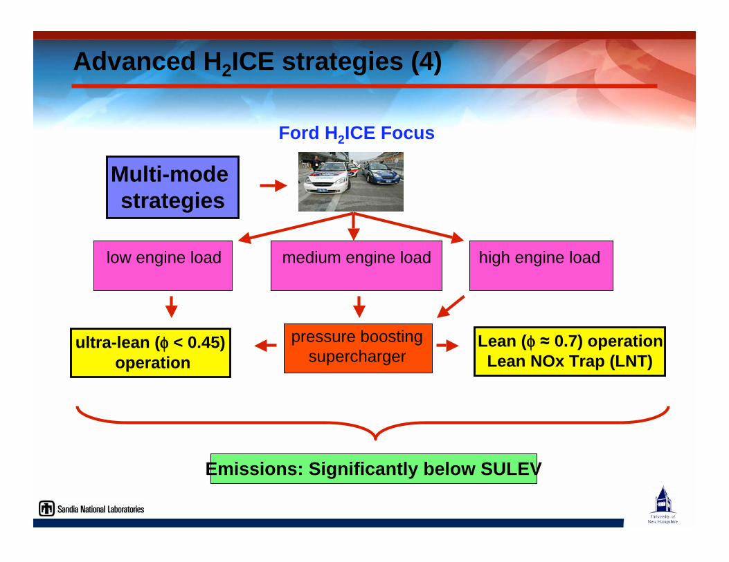
Multi-mode strategies
ultra-lean ( < 0.45) operation
low engine load
Emissions: Significantly below SULEV
medium engine load
pressure boosting
supercharger
Ford H2ICE Focus
high engine load
Lean ( 0.7) operationLean NOx Trap (LNT)
Advanced H2ICE strategies (4)
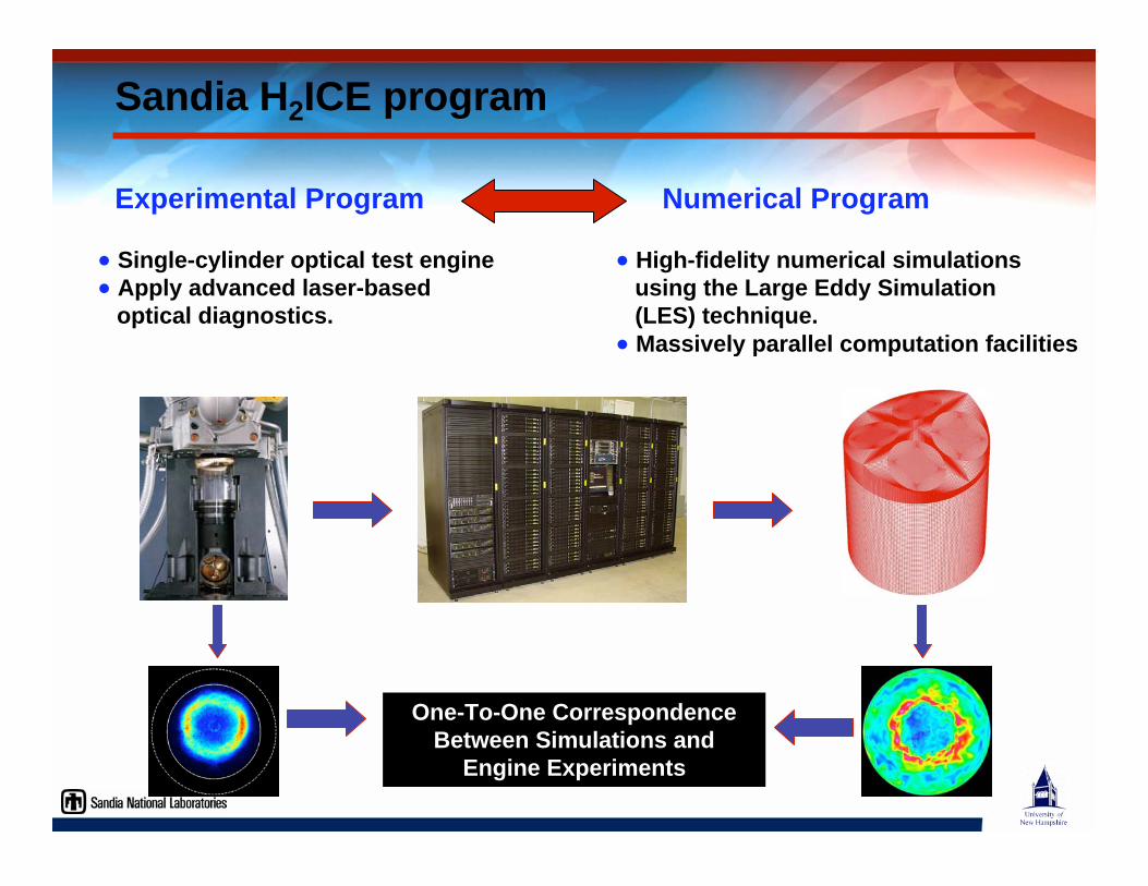
Numerical ProgramExperimental Program
Single-cylinder optical test engine Apply advanced laser-based
optical diagnostics.
High-fidelity numerical simulations using the Large Eddy Simulation (LES) technique.
Massively parallel computation facilities
One-To-One CorrespondenceBetween Simulations and
Engine Experiments
Sandia H2ICE program
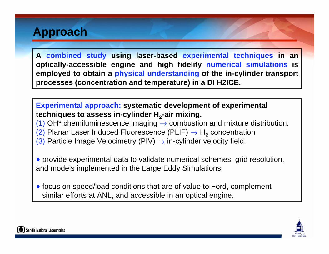
Approach
Experimental approach: systematic development of experimentaltechniques to assess in-cylinder H2-air mixing.(1) OH* chemiluminescence imaging combustion and mixture distribution.
(2) Planar Laser Induced Fluorescence (PLIF) H2 concentration
(3) Particle Image Velocimetry (PIV) in-cylinder velocity field.
provide experimental data to validate numerical schemes, grid resolution,
and models implemented in the Large Eddy Simulations.
focus on speed/load conditions that are of value to Ford, complement
similar efforts at ANL, and accessible in an optical engine.
A combined study using laser-based experimental techniques in anoptically-accessible engine and high fidelity numerical simulations isemployed to obtain a physical understanding of the in-cylinder transportprocesses (concentration and temperature) in a DI H2ICE.
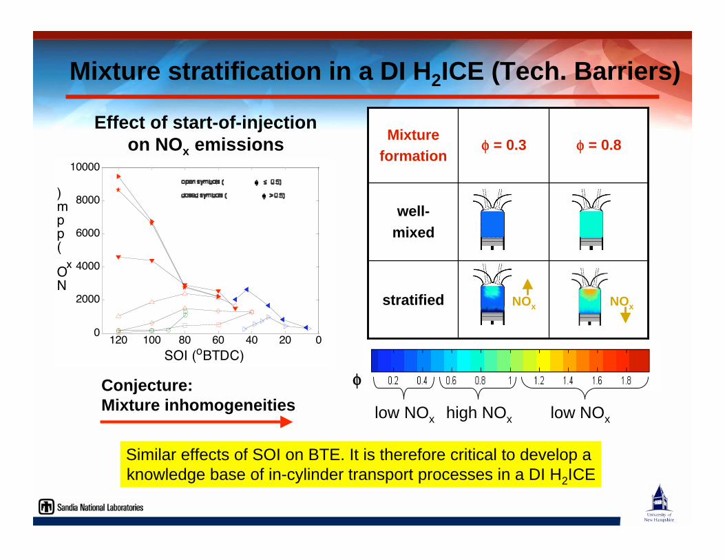
Mixture stratification in a DI H2ICE (Tech. Barriers)
0204060801001200
2000
4000
6000
8000
10000
SOI (oBTDC)
NO
x (ppm)
Conjecture:Mixture inhomogeneities
Effect of start-of-injectionon NOx emissions
low NOx high NOx low NOx
overall = 0.3
well-mixed
stratified
well-
mixed
= 0.8 = 0.3Mixture
formation
NOxNOx
Similar effects of SOI on BTE. It is therefore critical to develop a
knowledge base of in-cylinder transport processes in a DI H2ICE
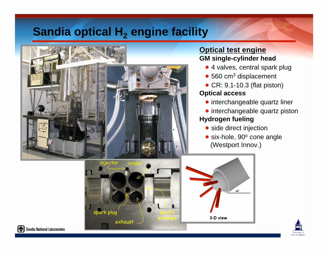
Optical test engineGM single-cylinder head
4 valves, central spark plug
560 cm3 displacement
CR: 9.1-10.3 (flat piston)
Optical access
interchangeable quartz liner
interchangeable quartz piston
Hydrogen fueling
side direct injection
six-hole, 90o cone angle
(Westport Innov.)
injector
spark plug
intake
exhaust
quartzquartzwindowswindows
Sandia optical H2 engine facility
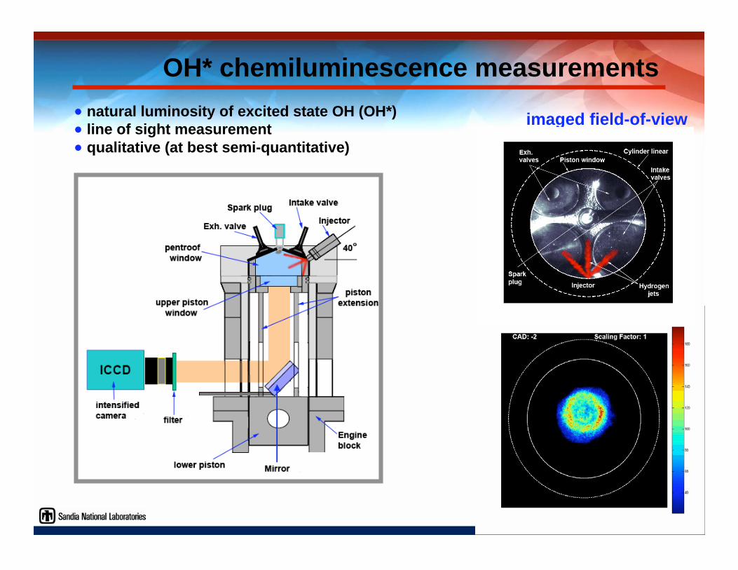
OH* chemiluminescence measurements
natural luminosity of excited state OH (OH*) line of sight measurement qualitative (at best semi-quantitative)
imaged field-of-view
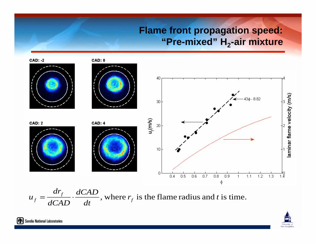
Flame front propagation speed:“Pre-mixed” H2-air mixture
time.is and radius flame theis where, trdt
dCAD
dCAD
dru f
f
f =
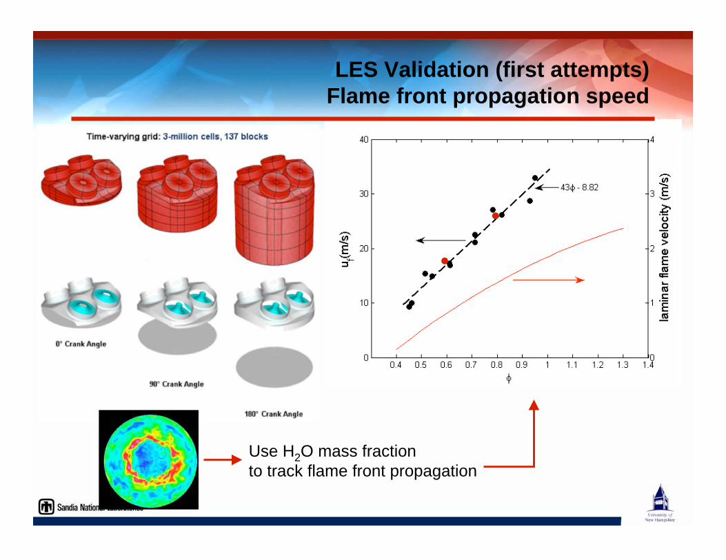
Use H2O mass fraction
to track flame front propagation
LES Validation (first attempts)Flame front propagation speed
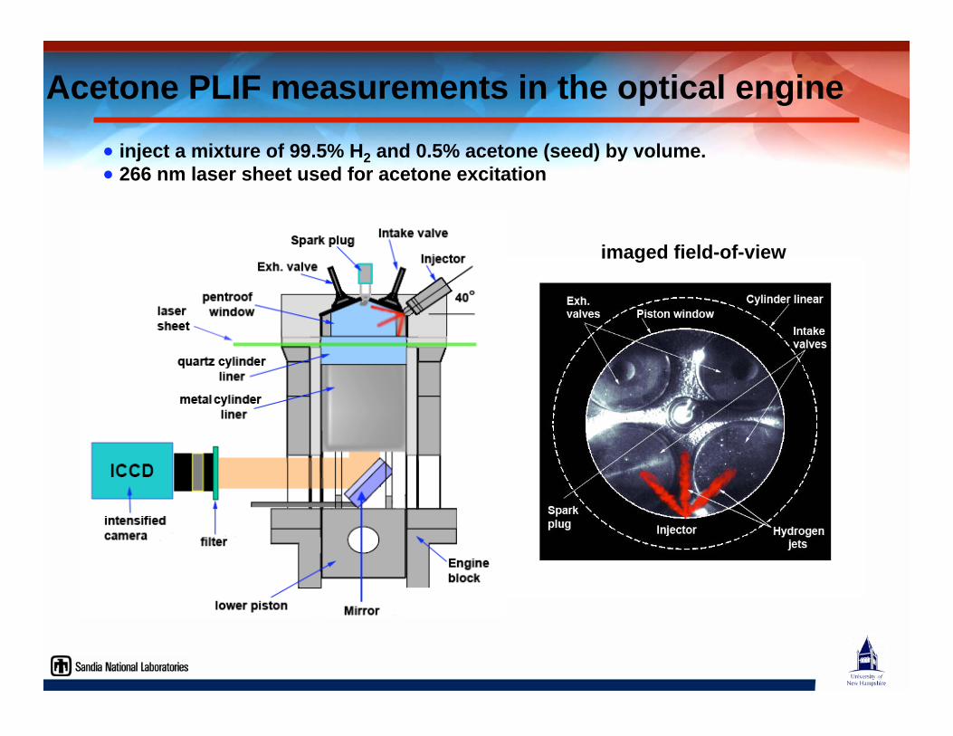
Acetone PLIF measurements in the optical engine
inject a mixture of 99.5% H2 and 0.5% acetone (seed) by volume. 266 nm laser sheet used for acetone excitation
imaged field-of-view
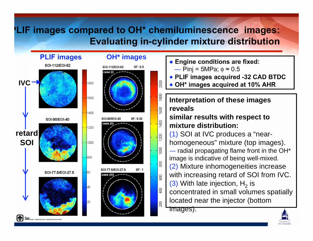
PLIF images compared to OH* chemiluminescence images:Evaluating in-cylinder mixture distribution
Engine conditions are fixed: — Pinj = 5MPa; 0.5
PLIF images acquired -32 CAD BTDC OH* images acquired at 10% AHR
PLIF images OH* images
Interpretation of these imagesrevealssimilar results with respect tomixture distribution:(1) SOI at IVC produces a “near-
homogeneous” mixture (top images). radial propagating flame front in the OH*
image is indicative of being well-mixed.
(2) Mixture inhomogeneities increase
with increasing retard of SOI from IVC.
(3) With late injection, H2 is
concentrated in small volumes spatially
located near the injector (bottom
images).
retardSOI
IVC
Summary
Hydrogen is an attractive fuel for future internal combustionengines.
H2ICEs will serve as an enabling end-use technology for building a hydrogen economy. • demonstrated efficiencies in excess of today’s gasoline engines.
• near-ZEV (Zero Emission Vehicle) performance
DI H2ICE is one of the most attractive advanced H2ICE options. • high power density
• mitigate preignition problems
• optimal charge stratification has the potential for:
- improved efficiency
- reduced emissions
Further research required to resolve technical barriers. • robust high pressure, high flow rate H2 injectors
• fundamental understanding of in-cylinder transport processes.


![2020MY .05 Cert · 1 day ago · Of testinp. (For flexible- and dual-fueled engines, the CERT values in brackets [ ] are those when tested on conventional test fuel. For multi-fueled](https://static.fdocuments.in/doc/165x107/5f2a8e3ab9a0223bc239e483/2020my-05-cert-1-day-ago-of-testinp-for-flexible-and-dual-fueled-engines.jpg)