ADVANCED HIGH PERFORMANCE SOLID WALL … high performance solid wall blanket concepts by c.p.c....
25
GA–A23900 ADVANCED HIGH PERFORMANCE SOLID WALL BLANKET CONCEPTS by C.P.C. WONG, S. MALANG, S. NISHIO, R. RAFFRAY, and S. SAGARA APRIL 2002
Transcript of ADVANCED HIGH PERFORMANCE SOLID WALL … high performance solid wall blanket concepts by c.p.c....

GA–A23900
ADVANCED HIGH PERFORMANCE SOLID WALLBLANKET CONCEPTS
byC.P.C. WONG, S. MALANG, S. NISHIO, R. RAFFRAY, and S. SAGARA
APRIL 2002

DISCLAIMER
This report was prepared as an account of work sponsored by an agency of the United StatesGovernment. Neither the United States Government nor any agency thereof, nor any of theiremployees, makes any warranty, express or implied, or assumes any legal liability orresponsibility for the accuracy, completeness, or usefulness of any information, apparatus,product, or process disclosed, or represents that its use would not infringe privately owned rights.Reference herein to any specific commercial product, process, or service by trade name,trademark, manufacturer, or otherwise, does not necessarily constitute or imply its endorsement,recommendation, or favoring by the United States Government or any agency thereof. The viewsand opinions of authors expressed herein do not necessarily state or reflect those of the UnitedStates Government or any agency thereof.

GA–A23900
ADVANCED HIGH PERFORMANCE SOLID WALLBLANKET CONCEPTS
byC.P.C. WONG, S. MALANG,† S. NISHIO,‡ R. RAFFRAY,∆ and S. SAGARA◊
This is a preprint of a paper presented at the 6th InternationalSymposium on Fusion Nuclear Technology, San Diego, California,April 7–12, 2001, and to be published in the Proceedings.
†Forschungszentrum Karlsruhe‡Japanese Atomic Energy Reseach Institute∆FERP, University of California, San Diego
◊LHD Project
Work supported bythe U.S. Department of Energy
under Contract DE-AC03-98ER54411
GENERAL ATOMICS PROJECT 30007APRIL 2002
C.P.C. WONG, et al. ADVANCED HIGH PERFORMANCE SOLID WALLBLANKET CONCEPTS
GENERAL ATOMICS REPORT GA-A23900 1
ABSTRACT
First wall and blanket (FW/blanket) design is a crucial element in the performance and
acceptance of a fusion power plant. High temperature structural and breeding materials are
needed for high thermal performance. A suitable combination of structural design with the
selected materials is necessary for D-T fuel sufficiency. Whenever possible, low afterheat, low
chemical reactivity and low activation materials are desired to achieve passive safety and
minimize the amount of high-level waste. Of course the selected fusion FW/blanket design will
have to match the operational scenarios of high performance plasma. The key characteristics of
eight advanced high performance FW/blanket concepts are presented in this paper. Design
configurations, performance characteristics, unique advantages and issues are summarized. All
reviewed designs can satisfy most of the necessary design goals. For further development, in
concert with the advancement in plasma control and scrape off layer physics, additional
emphasis will be needed in the areas of first wall coating material selection, design of plasma
stabilization coils, consideration of reactor startup and transient events. To validate the projected
performance of the advanced FW/blanket concepts the critical element is the need for 14 MeV
neutron irradiation facilities for the generation of necessary engineering design data and the
prediction of FW/blanket components lifetime and availability.

C.P.C. WONG, et al. ADVANCED HIGH PERFORMANCE SOLID WALLBLANKET CONCEPTS
GENERAL ATOMICS REPORT GA-A23900 3
1. INTRODUCTION
Advanced FW/blanket designs have always been aiming for adequate nuclear and high
thermal performance, including the use of low activation materials. In recent years we have
continued the development and application of SiCf/SiC composite material for use with solid and
liquid breeder materials. We continued to evaluate the use of V-alloy with stagnant Li and self-
cooled Flibe coolant options. We have also evaluated the use of refractory alloys and selected W-
alloys for further assessment. This paper presents eight advanced solid wall blanket designs with
different combinations of structural, tritium breeding materials and cooling options. Key
parameters of these advanced solid first wall designs are presented in Table 1. Summary
descriptions are given on the configuration, performance characteristics, and identification of
special features and critical issues. Subsequently, we comment on how these designs have
satisfied the required and desirable attributes for the reactor design. Future needs and directions
on the development of advanced FW/blanket designs are also provided in this paper. For a more
complete review of SiCf/SiC composite designs, readers are referred to the paper presented in this
conference titled, “Progress in Blanket Designs Using SiCf/SiC composites” [1]. It should be
noted that we have selected a few recent FW/blanket concepts for comparison. Other well known
advanced concepts like the V-alloy Li-self-cooled FW/blanket concept have not been included in
this paper.

ADVANCED HIGH PERFORMANCE SOLID WALL C.P.C. WONG, et al.BLANKET CONCEPTS
4 GENERAL ATOMICS REPORT GA-A23900
Table 1Key design parameters of eight advanced FW/blanket designs
1 2 3 4 5 6 7 8
A-SSTR-2 A-HCPB TAURO ARIES-AT1
V/Li/He W/Li/He EVOLVE FFHR-2
Application Tokamak Tokamak Tokamak Tokamak Tokamak Tokamak Tokamak Stellerator
Pfusion, GW 4 4.5 3 1.7 1.9 3.5 3.5 1
FW heat flux, MW/m2 1.4 (ave.) 0.6 (peak) 0.5 (ave)0.69(peak)
0.26 (ave)0.34(peak)
0.34 2 (peak) 2 (peak) 0.09
Neutron wall loading,MW/m2
6 (ave.) 2.76(ave.)3.5 (peak)
22.8 (peak)
3.2 (ave) 2.9 (ave) 7(peak) 10 (peak) 1.7
Structural material SiCf/SiCcomposite
SiCf/SiC SiCf/SiCcomposite
SiCf/SiCcomposite
V-4Cr-4Ti W-alloy W-alloy V-4Cr-4Ti
FW thickness, mm 4–6 3 6 4+1(armor)
3 3 3 5
Structural materialTmax-allowed, °C
1100 1300 1300 1000 700 1400 1400 750
FW material, Kth,W/m-K
10–50 15 15 20 35 85@1400 K
85@ 1400 K
35
Tritium breeder (neutronmultiplier)
Li2TiO3(Be)
Li4SiO4(Be)
Pb-17Li(none)
Pb-17Li(none)
Li(none)
Li(none)
Li(none)
Flibe(Be)
Fuel form Pebbles Pebbles Liquid Liquid Liquid Liquid Liquid Liquid
Coolant(Pressure, MPa)
He(10)
He(8 )
Pb-17Li(1.5)
Pb-17Li(1)
He(18)
He(12)
Vaporized Li(0.037)
Flibe(0.6)
Tritium breeding ratio(Li-6 enrichment)
1.37 (local)(natural)
1.09“3-D”
(optimized)
1.37(local)(90%)
1.1“3-D”
(natural)
1.4 (local)(natural)
1.43 (local)(35%)
1.33 (local)(natural)
1.4(local)(50%)
Coolant Tin, °C 600 350 650 654 400 800 1100 450
Coolant Tout, °C 900 700 860 1100 650 1100 1200 550
Power conversion cycle CCGT2 CCGT2 CCGT2 CCGT2 CCGT2 CCGT2 CCGT2 CCGT2
ηth, % 51 44.8 >47 58.5 46 57.5 58 45
1For ARIES-AT the surface heat flux used for temperature and stress calculation was 0.7 MW/m2.
2Closed Cycle Gas Turbine

C.P.C. WONG, et al. ADVANCED HIGH PERFORMANCE SOLID WALLBLANKET CONCEPTS
GENERAL ATOMICS REPORT GA-A23900 5
2. DESIGN SUMMARY
1. The A-SSTR-2 is a compact power reactor (Ro = 6.2 m, a = 1.5 m) with a fusion power
output of 4 GW. Its FW/blanket is a SiCf/SiC composite, Li2TiO3 (Be) pebble breeder,
helium-cooled design [2]. It has an average neutron wall loading of 6 MW/m2 and an
average heat flux of 1.4 MW/m2. With helium at 10 MPa, the projected Brayton cycle
thermal efficiency is 51%. The first wall and blanket small module configuration is
shown in Fig. 1. The coolant helium flows towards the first wall from the outer annulus
of the concentric coolant tube and cools the first wall. It then turns and cools the Be and
the breeder pebble zones while exiting the blanket module from the inner channel of the
concentric coolant tube. Key parameters of the design are presented in Table 1. In
addition to the development need of the SiCf/SiC composite structural material, the study
also identified the need to have high thermal conductivity of 50 W/m-K for SiCf/SiC
when the material is also used to handle the high surface heat flux at the divertor.
Small Module
500
He Coolant
(Dimensions in mm)
Be
Li2TiO3
43064
5
115
280
Fig.1. A-SSTR-2 FW/blanket module.
2. The A-HCPB FW/blanket [3] is proposed as a candidate in the European program as a
DEMO relevant blanket. It is a SiCf/SiC composite, Li4SiO4 ceramic pebble breeder,

ADVANCED HIGH PERFORMANCE SOLID WALL C.P.C. WONG, et al.BLANKET CONCEPTS
6 GENERAL ATOMICS REPORT GA-A23900
helium-cooled design, with a projected thermal efficiency of ~45%. Key design
parameters are presented in Table 1. The FW/blanket configuration is shown in Fig. 2,
which shows a different approach than for the A-SSTR-2 FW/blanket design. For the
A-HCPB design there are two SiCf/SiC components: a helium-cooled box formed by a
series of parallel tubes forming the first wall, and SiCf/SiC cooling plates formed by long
meanders separating the breeder ceramic pebbles from the Be pebbles. Since the helium
coolant is at 8 MPa, a burst disk is proposed to handle the accidental situation of high-
pressure coolant leakage, which may cause pressurization of the blanket module.
He PurgeFlow
Graphite Reflector
CeramicPebbleBed
BePebbleBed
FW Shell
BZ Meanders
He Outlet
He Inlet
Fig. 2. Advanced HCPB FW/blanket.
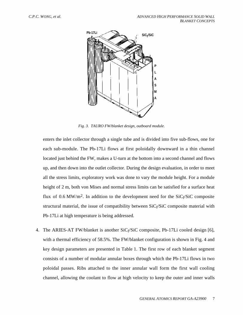
3. The TAURO design [4] is based on the specification from the SEAFP study [5]. It is a
SiCf/SiC composite, self-cooled Pb-17Li FW/blanket design, with a projected thermal
efficiency of > 47%. This combination of materials avoids the development of electrically
insulating wall coatings necessary for the metallic structure and conducting fluid self-
cooled design. It also can be designed to lower system pressure, and the geometry is more
compact by eliminating the helium void fraction when compared to the high-pressure
helium-cooled designs. Parameters of this design are presented in Table 1. The TAURO
FW/blanket configuration is shown in Fig. 3. Each outboard segment is poloidally
divided into several straight modules, attached on one common thick back-plate but
cooled independently. The feeding pipes are located behind the module. The coolant
C.P.C. WONG, et al. ADVANCED HIGH PERFORMANCE SOLID WALLBLANKET CONCEPTS
GENERAL ATOMICS REPORT GA-A23900 7
SiCf/SiCPb-17Li
P
L
A
S
M
A
Fig. 3. TAURO FW/blanket design, outboard module.
enters the inlet collector through a single tube and is divided into five sub-flows, one for
each sub-module. The Pb-17Li flows at first poloidally downward in a thin channel
located just behind the FW, makes a U-turn at the bottom into a second channel and flows
up, and then down into the outlet collector. During the design evaluation, in order to meet
all the stress limits, exploratory work was done to vary the module height. For a module
height of 2 m, both von Mises and normal stress limits can be satisfied for a surface heat
flux of 0.6 MW/m2. In addition to the development need for the SiCf/SiC composite
structural material, the issue of compatibility between SiCf/SiC composite material with
Pb-17Li at high temperature is being addressed.
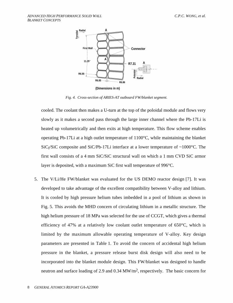
4. The ARIES-AT FW/blanket is another SiCf/SiC composite, Pb-17Li cooled design [6],
with a thermal efficiency of 58.5%. The FW/blanket configuration is shown in Fig. 4 and
key design parameters are presented in Table 1. The first row of each blanket segment
consists of a number of modular annular boxes through which the Pb-17Li flows in two
poloidal passes. Ribs attached to the inner annular wall form the first wall cooling
channel, allowing the coolant to flow at high velocity to keep the outer and inner walls
ADVANCED HIGH PERFORMANCE SOLID WALL C.P.C. WONG, et al.BLANKET CONCEPTS
8 GENERAL ATOMICS REPORT GA-A23900
Connector
R7.31 A
A
A
Polo
idal
Toro
idal
Radial
Radial
R6.86R6.85
R6.55
11.25°
First Wall
(Dimensions in m)
Fig. 4. Cross-section of ARIES-AT outboard FW/blanket segment.
cooled. The coolant then makes a U-turn at the top of the poloidal module and flows very
slowly as it makes a second pass through the large inner channel where the Pb-17Li is
heated up volumetrically and then exits at high temperature. This flow scheme enables
operating Pb-17Li at a high outlet temperature of 1100°C, while maintaining the blanket
SiCf/SiC composite and SiC/Pb-17Li interface at a lower temperature of ~1000°C. The
first wall consists of a 4 mm SiC/SiC structural wall on which a 1 mm CVD SiC armor
layer is deposited, with a maximum SiC first wall temperature of 996°C.
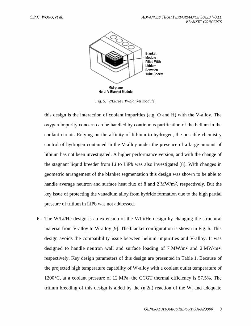
5. The V/Li/He FW/blanket was evaluated for the US DEMO reactor design [7]. It was
developed to take advantage of the excellent compatibility between V-alloy and lithium.
It is cooled by high pressure helium tubes imbedded in a pool of lithium as shown in
Fig. 5. This avoids the MHD concern of circulating lithium in a metallic structure. The
high helium pressure of 18 MPa was selected for the use of CCGT, which gives a thermal
efficiency of 47% at a relatively low coolant outlet temperature of 650°C, which is
limited by the maximum allowable operating temperature of V-alloy. Key design
parameters are presented in Table 1. To avoid the concern of accidental high helium
pressure in the blanket, a pressure release burst disk design will also need to be
incorporated into the blanket module design. This FW/blanket was designed to handle
neutron and surface loading of 2.9 and 0.34 MW/m2, respectively. The basic concern for
C.P.C. WONG, et al. ADVANCED HIGH PERFORMANCE SOLID WALLBLANKET CONCEPTS
GENERAL ATOMICS REPORT GA-A23900 9
Blanket ModuleFilled WithLithiumBetweenTube Sheets
Mid-planeHe-Li-V Blanket Module
Fig. 5. V/Li/He FW/blanket module.
this design is the interaction of coolant impurities (e.g. O and H) with the V-alloy. The
oxygen impurity concern can be handled by continuous purification of the helium in the
coolant circuit. Relying on the affinity of lithium to hydrogen, the possible chemistry
control of hydrogen contained in the V-alloy under the presence of a large amount of
lithium has not been investigated. A higher performance version, and with the change of
the stagnant liquid breeder from Li to LiPb was also investigated [8]. With changes in
geometric arrangement of the blanket segmentation this design was shown to be able to
handle average neutron and surface heat flux of 8 and 2 MW/m2, respectively. But the
key issue of protecting the vanadium alloy from hydride formation due to the high partial
pressure of tritium in LiPb was not addressed.
6. The W/Li/He design is an extension of the V/Li/He design by changing the structural
material from V-alloy to W-alloy [9]. The blanket configuration is shown in Fig. 6. This
design avoids the compatibility issue between helium impurities and V-alloy. It was
designed to handle neutron wall and surface loading of 7 MW/m2 and 2 MW/m2,
respectively. Key design parameters of this design are presented in Table 1. Because of
the projected high temperature capability of W-alloy with a coolant outlet temperature of
1200°C, at a coolant pressure of 12 MPa, the CCGT thermal efficiency is 57.5%. The
tritium breeding of this design is aided by the (n,2n) reaction of the W, and adequate

ADVANCED HIGH PERFORMANCE SOLID WALL C.P.C. WONG, et al.BLANKET CONCEPTS
10 GENERAL ATOMICS REPORT GA-A23900
First Wall/BlanketInlet – 19 cm dia.
First Wall Shroud with(12) 2.2 cm dia.
Cooling Passages per shroud
Blanket Inlet19 cm dia.
Blanket Tubes22 cm dia. Blanket Outlet
22 cm dia.First Wall Outlet
Blanket Inlet19 cm dia.
Lithium“Can”
(Temperature in °C)
Fig. 6. W/Li/He FW/blanket module.
tritium can be produced. The critical issues for this design relate to joining and
fabrication techniques for W-alloy. Both V-alloy and W-alloy helium cooled designs also
have the basic issues of large helium-void fraction in the blanket and the requirement for
a large coolant plenum at the back of the blanket as shown in Fig. 6.
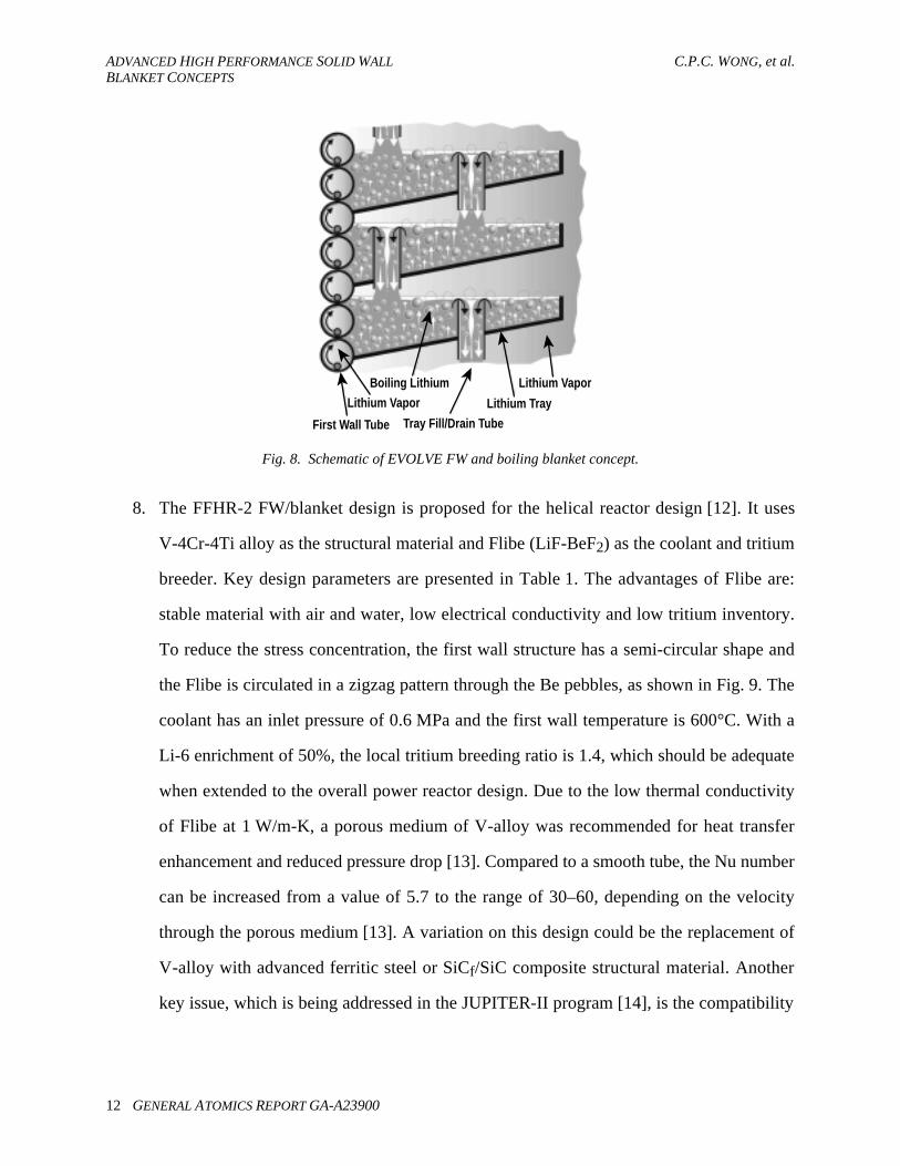
7. To achieve high thermal performance at high power density, the EVOLVE W-alloy
FW/blanket concept proposes to use the vaporization of lithium as the active coolant with
a lithium vapor outlet temperature of 1200°C, leading to a helium CCGT efficiency of
~58% [10]. This design operates at a low system pressure of 0.037 MPa. Key design
parameters are presented in Table 1. The pumping of the lithium circulation in the FW
tubes is performed by capillary suction as shown in Fig. 7. For the pumping of liquid Li,
the basic design criterion is that the capillary pressure at the first wall must overcome the
sum of all frictional and MHD pressure losses in the FW/blanket coolant loop. As shown
in Fig. 7 the proposed design has a first wall tube diameter of about 6 cm, a lithium
channel width of about 2 mm and a capillary opening of 0.5 mm. The blanket can be

C.P.C. WONG, et al. ADVANCED HIGH PERFORMANCE SOLID WALLBLANKET CONCEPTS
GENERAL ATOMICS REPORT GA-A23900 11
Section B – B
Section A – A
A
Bt
A
BB
FirstWall
Liquid Li
Li-Vapor
Bt
Fig. 7. The transpiration-cooled FW/blanket schematic (section B-B is the top view and section A-A is the side viewof the design).
cooled by an extension of the FW Li-vaporization cooling as shown in Fig. 7, or it can be
cooled by the boiling of lithium as shown in Fig. 8. For the capillary vaporization cooled
option, the lithium slabs in the blanket are held in walls with capillary openings. For this
blanket option, the characteristic dimensions are then determined based on the
superheating of the lithium. These are passively cooled FW/blanket options. Basic issues
of these designs are the concern of W-alloy component fabrication, the MHD effects on
the capillary cooling of lithium.
Both W-alloy designs have high afterheat, but this potential safety issue could be handled
by the incorporation of passive coolant loop designs [10]. Furthermore, due to the
generation of 108mRe from nuclear interaction with base elements in the W-alloy, the
goal of class-C waste disposal at the end of reactor life cannot be satisfied [11].
ADVANCED HIGH PERFORMANCE SOLID WALL C.P.C. WONG, et al.BLANKET CONCEPTS
12 GENERAL ATOMICS REPORT GA-A23900
Lithium VaporBoiling Lithium
Lithium Vapor
First Wall Tube
Lithium Tray
Tray Fill/Drain Tube
Fig. 8. Schematic of EVOLVE FW and boiling blanket concept.
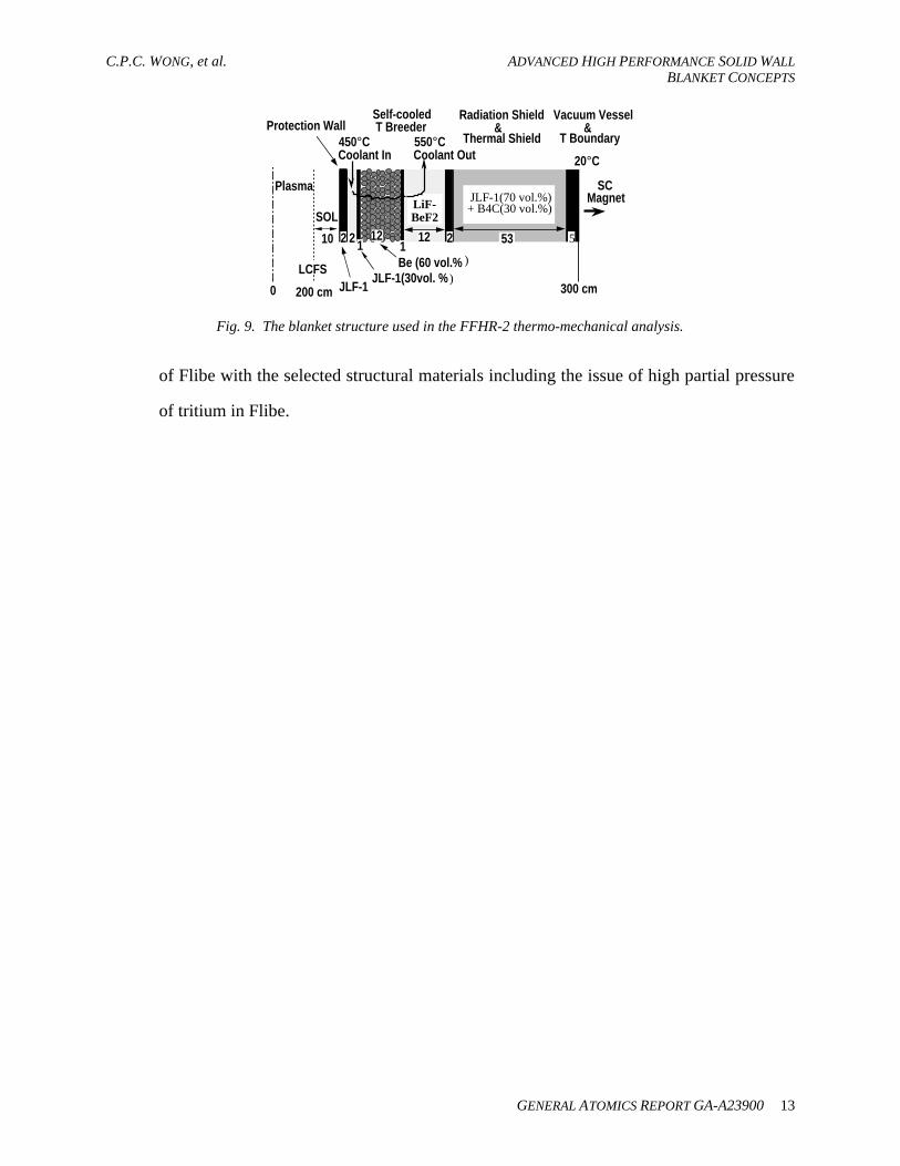
8. The FFHR-2 FW/blanket design is proposed for the helical reactor design [12]. It uses
V-4Cr-4Ti alloy as the structural material and Flibe (LiF-BeF2) as the coolant and tritium
breeder. Key design parameters are presented in Table 1. The advantages of Flibe are:
stable material with air and water, low electrical conductivity and low tritium inventory.
To reduce the stress concentration, the first wall structure has a semi-circular shape and
the Flibe is circulated in a zigzag pattern through the Be pebbles, as shown in Fig. 9. The
coolant has an inlet pressure of 0.6 MPa and the first wall temperature is 600°C. With a
Li-6 enrichment of 50%, the local tritium breeding ratio is 1.4, which should be adequate
when extended to the overall power reactor design. Due to the low thermal conductivity
of Flibe at 1 W/m-K, a porous medium of V-alloy was recommended for heat transfer
enhancement and reduced pressure drop [13]. Compared to a smooth tube, the Nu number
can be increased from a value of 5.7 to the range of 30–60, depending on the velocity
through the porous medium [13]. A variation on this design could be the replacement of
V-alloy with advanced ferritic steel or SiCf/SiC composite structural material. Another
key issue, which is being addressed in the JUPITER-II program [14], is the compatibility
C.P.C. WONG, et al. ADVANCED HIGH PERFORMANCE SOLID WALLBLANKET CONCEPTS
GENERAL ATOMICS REPORT GA-A23900 13
Be (60 vol.% )
JLF-1(70 vol.%) + B4C(30 vol.%)
200 cm 300 cm
Self-cooled T Breeder
Radiation Shield Vacuum Vessel
SCMagnet
LCFS
Protection Wall
10
Coolant Out Thermal Shield 450°C 550°C
Coolant In 20°C
12 53
T Boundary&
JLF-1
LiF-BeF2
22 12 52
JLF-1(30vol. % )
1 1
&
0
Plasma
SOL
Fig. 9. The blanket structure used in the FFHR-2 thermo-mechanical analysis.
of Flibe with the selected structural materials including the issue of high partial pressure
of tritium in Flibe.
C.P.C. WONG, et al. ADVANCED HIGH PERFORMANCE SOLID WALLBLANKET CONCEPTS
GENERAL ATOMICS REPORT GA-A23900 15
3. NECESSARY AND DESIRABLE ATTRIBUTES ASSESSMENT
In the following we will assess the eight FW/blanket designs by considering the necessary
and desirable attributes for power reactor designs. The goal is not to provide critical review of
any specific FW/blanket design, but to identify general trends in order to provide directions for
future research.
3.1. Adequate tritium breeding
All designs summarized above can potentially provide adequate tritium breeding with at least
the use of Li-6 enrichment or Be as the neutron multiplier. Solid breeder and Flibe breeder
designs will require the use of a Be neutron multiplier and, accordingly, will have to be designed
to accommodate the irradiation swelling and tritium inventory of the Be-neutron multiplier. Li-6
enrichment may also be needed for these designs. Li-17Pb designs can be designed with or
without the use of Li-6 enrichment. V-Li/He and EVOLVE designs are the only two that can
provide adequate tritium breeding without the use of Li-6 enrichment or a neutron multiplier.
3.2. Structural design
With a thin first wall thickness between 2 to 5 mm, all designs can be shown to satisfy the
structural design criteria of the given material under steady state operation. The key uncertainty
is the credibility of the given structural material design data since none of the material has been
tested under high 14 MeV fusion neutron fluence conditions. Even though significant effort has
been devoted to the extrapolation of design properties based on fission irradiation data [15],
fusion irradiation data will still be needed. The degree of extrapolation of design data, in terms of
higher to lower credibility, could be ranked in the order of V-alloy, W-alloy and SiCf/SiC
composite material.

ADVANCED HIGH PERFORMANCE SOLID WALL C.P.C. WONG, et al.BLANKET CONCEPTS
16 GENERAL ATOMICS REPORT GA-A23900
3.3. Thermal hydraulics
Thermal hydraulics designs will mainly depend on the blanket configuration, thermal power
input, selected structural and FW/blanket coolant materials. Helium coolant options are designed
with small channel tubes in order to withstand the high pressure of 8–18 MPa. Pb-17Li and Flibe
coolants can operate at much lower system pressure in the range of 1 to 1.5 MPa. The lowest
pressure design is the vaporized lithium EVOLVE design, which uses a coolant pressure of
0.037 MPa. All selected designs have avoided the large MHD pressure drop when liquid metal is
circulated at high speed in metallic channels in a magnetic confinement system. It should be
noted that due to the low thermal conductivity of Flibe at 1 W/m-K, in order to remove the
relatively low heat flux of 0.1 MW/m2, an extended heat transfer option like the use of a porous
medium is necessary for the helical reactor FFHR-2 design [13].
3.4. Material issues
For the designs that we have reviewed, it is obvious that we are investigating materials with
three key properties: high strength, high allowable maximum temperature and low activation.
W-alloy alloy does not have the low activation property, but it has projected high strength and
high thermal conductivity of 85 W/m-K at high temperature of 1300°C. This led to the low
pressure vaporized-lithium cooled design.
The key concerns for the V-alloy, W-alloy and SiCf/SiC materials are mechanical and
thermal property degradation under high fusion neutron fluence. It is obvious that material
irradiation facilities such as the International Fusion Materials Irradiation Facility (IFMIF) [15]
and volumetric neutron source (VNS) [16] should be constructed and made available for fusion
materials qualification. Correspondingly, fusion relevant design codes for metallic and ceramic
composite materials will have to be developed.
Furthermore, compatibility issues under a fusion environment for solid-breeder/Be/SiC,
Pb-17Li/SiC, He-impurities/V-alloy, He-impurities/W-alloy, Li/W-alloy, Pb-17Li/V-alloy, and
C.P.C. WONG, et al. ADVANCED HIGH PERFORMANCE SOLID WALLBLANKET CONCEPTS
GENERAL ATOMICS REPORT GA-A23900 17
Flibe/V-alloy systems, covering the FW/blanket options that we are considering, will have to be
addressed before we can even consider the question of component lifetime.
Feasibility issues of component fabrication, especially for SiCf/SiC and W-alloy materials,
will have to be addressed. Efforts have been initiated for the ceramic SiCf/SiC composite
material [18]. Similarly, the fabrication development on V-alloy through the more conventional
metallic alloy development path has also been initiated [19].
It should be noted that since we have no operation experience with these advanced
FW/blanket designs, we are in no position to answer the very important questions of component
lifetime and availability. Therefore, we cannot underscore enough the importance of initiating the
integrated first wall and blanket testing under the ITER program [20] and the fusion development
facility (FDF) [21].
3.5. High power density
As we can see from Table 1, the average neutron wall loading covers the range of 3 to
8 MW/m2 for tokamak reactors and has a lower value of 1.7 MW/m2 for the helical reactor. At
least for the tokamak reactors with the output power range of 1–2 GW(e), the selected
FW/blanket designs cover the optimum neutron wall loading range of 4–7 MW/m2 when the cost
of electricity is taken into consideration [22].
3.6. Safety and environmental impacts
3.6.1. Low tritium inventory and favorable tritium control
For lithium breeder blanket options, because of the affinity of lithium to hydrogen and the
proposed low concentration of tritium in the lithium loop, the inventory of tritium for these
designs should be low and its routine release can be kept to a minimum. Similarly, solid breeders
have the option of controlling the operating characteristics by the use of a purge flow stream.
Therefore the concerns of tritium inventory and release in solid breeder material could also be

ADVANCED HIGH PERFORMANCE SOLID WALL C.P.C. WONG, et al.BLANKET CONCEPTS
18 GENERAL ATOMICS REPORT GA-A23900
controlled. However, when Be is used as the neutron multiplier, the potential tritium inventory
and subsequent release remain to be addressed. For breeding materials like Pb-17Li and Flibe,
due to their low solubility of hydrogen, the control of routine and accidental tritium release will
be necessary. Furthermore, when the structural material is taken into account, the potential
tritium inventory in SiCf/SiC composite, V and W-alloys is still uncertain.
3.6.2. Low afterheat, passive safety and minimum radioactivity release
With the exception of W-alloy, the reviewed designs have relatively low afterheat, which
would make it easier to fulfill the goal of passive safety. On the other hand, even with the much
higher afterheat from W-alloy, built-in natural circulation loops can be used to maintain passive
safety under the loss of power accident, while meeting the dose limit of 10 mSv at the site
boundary during a worst-case accident scenario [10]. For designs with high pressure helium,
rupture disks in the coolant circuit connected to a discharge vessel will be required to protect the
blanket from accidental pressurization in case of heat exchanger failure. An example of this is
given in the A-HCPB design [3].
When Pb-17Li is used as the blanket coolant the formation of 210Po, which has a very low
activity limit of 0.001 wppb, should be controlled. Since 210Po is generated from 209Bi as a
subsequent nuclear reaction and decaying beginning from 208Pb, the recommendation has been
the on-line removal of Bi during blanket operation [23].
3.6.3. Class-C waste disposal
With the exception of W-alloy designs, we have been considering low activation FW/blanket
designs. The key is the necessary control of selected impurities, e.g. Nb to less than 1 wppm.
Both SiCf/SiC and V-alloy at the end of a 40 full power year life, and after a waiting period of
ten years, can be treated as class-C waste. SiCf/SiC has the disadvantage of having to dispose off
a larger volume of low-level waste than for a V-alloy design. For metallic structures, recycling of
irradiated material has been considered as a viable option for waste disposal [24], leading to a
C.P.C. WONG, et al. ADVANCED HIGH PERFORMANCE SOLID WALLBLANKET CONCEPTS
GENERAL ATOMICS REPORT GA-A23900 19
much-reduced amount of waste to be considered as high-level waste. For W-alloy, due to the
formation of Re from the W metal, W-alloy designs at the end of life will have a waste disposal
ratio exceeding the qualification as class-C waste [11].
3.7. High power conversion efficiency
Table 1 shows that all design options presented can meet the high thermal performance
requirement with the use of Brayton cycle power conversion option. High thermal efficiency of
>43% is projected. Higher efficiency of >57% can be reached either by the use of high
temperature W-alloy structural material [9,10], or by the innovative routing of the coolant [6]
when SiCf/SiC composite is used. In the future, parallel development of the advanced fusion
FW/blanket and advanced Brayton cycle will be necessary [24].
3.8. First wall coating and coupling with the divertor design
For a tokamak reactor design, there is a trade-off between the first wall heat flux and the
divertor heat flux. The FW/blanket designs will have to be coordinated with the proposed
schemes for plasma detachment at the divertor, which is to reduce the peak divertor heat flux
with the corresponding increase of the surface heat flux at the first wall, due to impurity
radiation. Furthermore, there is still the active research area of material surface erosion at the
divertor and the first wall. Presently, the physics of particle and energy transport in the scrape off
layer and the layer just inside the last closed flux surface of the tokamak is far from understood.
Preliminary results show that about equal contributions of impurities getting into the plasma core
may be coming from the first wall and the divertor. Accordingly, we will have to increase our
attention in the selection of suitable first wall coating material in order to maximize the first wall
component lifetime with minimum erosion rate and yet, at the same time, only generate the
amount of eroded material with acceptable atomic weight in coordination with the necessary high
performance of the plasma.

ADVANCED HIGH PERFORMANCE SOLID WALL C.P.C. WONG, et al.BLANKET CONCEPTS
20 GENERAL ATOMICS REPORT GA-A23900
3.9. Compatibility with plasma operation
It should be noted that up to now the design of advanced FW/blanket designs have been
focusing on key requirements and goals of high thermal performance at steady-state, low
activation design and passive safety. Issues of reactor start-up, especially when liquid metal is
utilized, and response to disruption have not been addressed. These issues will have to be
assessed with increase depth when the coupling between plasma and reactor operating is better
understood. Another area of design that will have to be incorporated in future advanced tokamak
FW/blanket studies is the accommodation of passive and active plasma stabilization coils, which
will be imbedded in the FW/blanket system. These sets of coils will also have major impacts on
the nuclear performance, mechanical, electrical and thermal hydraulics designs. Even though
some of these issues are being addressed by reactor design systems studies, the FW/blanket
assessment community will have to be directly involved since these issues will have significant
impacts on the performance and lifetime of our designs.
C.P.C. WONG, et al. ADVANCED HIGH PERFORMANCE SOLID WALLBLANKET CONCEPTS
GENERAL ATOMICS REPORT GA-A23900 21
4. CONCLUSION
Eight advanced high performance solid wall blanket concepts were reviewed. Innovative
designs have been identified to simplify the mechanical design and reduce the operational system
pressure. These designs have been focusing on satisfying performance requirements and goals on
tritium breeding adequacy, high thermal performance and passive safety. Significant fabrication
uncertainties remain when SiCf/SiC composite and W-alloy are proposed as structural materials.
Basic fusion engineering design data on V-alloy, SiCf/SiC composite and W-alloy materials are
lacking, and this can only be addressed satisfactorily by 14 MeV neutron experiments like IFMIF
and integrated testing device like FDF. Using a device like ITER to provide preliminary
FW/blanket testing will also be useful. In the near future, when the coupling between the plasma
operations with the FW/blanket design becomes more matured, advanced FW/blanket design
assessment should include the selection of suitable first wall coating material, plasma
stabilization coil design, reactor startup and the handling of disruptions. These data will then help
us to begin considering the issues of components lifetime and availability.

C.P.C. WONG, et al. ADVANCED HIGH PERFORMANCE SOLID WALLBLANKET CONCEPTS
GENERAL ATOMICS REPORT GA-A23900 23
REFERENCES
[1] L. Giancarli et al., “Progress in blanket designs using SiCf/SiC composites,” these
proceedings.
[2] S. Nishio et al., “Conceptual design of advanced steady-state tokamak reactor,” 18th IAEA
Fusion Energy Conference, IAEA-CN-77/FTP2/14, Sorrento, Italy, (2000).
[3] L.V. Boccaccini, et al., “Advanced helium cooled pebble bed blanket with SiCf/SiC as
structural material,” Fusion Engineering and Design 49-50 (2000) 491-497.
[4] H. Golfier, et al., “Performance of the TAURO blanket system associated with a liquid-
metal cooled divertor, “Fusion Engineering and Design 49-50 (2000) 559-565.
[5] I. Cook, Fusion Engineering and Design 25 (1994) 179.
[6] A.R. Raffray, et al., “ARIES-AT blanket and divertor,” Fusion Technology, Vol. 39,
(2001) 429-433.
[7] C.P.C. Wong et al., “Evaluation of U.S. demo helium-cooled blanket options,” Proc. 16th
IEEE/NPSS Symp. on Fusion Engineering, September 30–October 5, 1995, Champaign,
Illinois, Vol. 2, p. 1145 (Institute of Electrical and Electronics Engineers, Inc. Piscataway,
New Jersey, 1996).
[8] C.P.C. Wong et al., “The low aspect ratio design concept – possibility of an acceptable
fusion power system,” Proc. 17th IEEE/NPSS Symp. on Fusion Engineering, October 6–
10, 1997, San Diego, California, Vol. 2, p. 1051 (Institute of Electrical and Electronics
Engineers, Inc. Piscataway, New Jersey, 1998).
[9] C.P.C. Wong et al., “Helium-cooled refractory alloys first wall and blanket evaluation,”
Fusion Engineering and Design 49-50 (2000) 709-717.
[10] C.P.C. Wong et al., “Evaluation of the tungsten alloy vaporization lithium first wall and
blanket concept,” Fusion Technology, Vol. 39, part 2, (2001) 815.
ADVANCED HIGH PERFORMANCE SOLID WALL C.P.C. WONG, et al.BLANKET CONCEPTS
24 GENERAL ATOMICS REPORT GA-A23900
[11] K. McCarthy et al., “Comparison of the safety and environmental characteristics of
refractory alloys under consideration in APEX,” Fusion Technology, Vol. 39, (2001)
951-955.
[12] A. Sagara et al., “Design and development of the Flibe blanket for helical-type fusion
reactor FFHR,” Fusion Engineering and Design 49-50 (2000) 661-666.
[13] S. Chiba et al., “Heat transfer enhancement for a molten salt Flibe channel,” Fusion
Technology Vol. 39, (2001) NEED PAGE NUMBER.
[14] D.K. Sze et al., “FliBe assessment,” Fusion Technology, Vol. 39, part 2, (2002) 747.
[15] S.J. Zinkle, N.M. Ghoniem, “Operating temperature windows for fusion reactor structural
mateials,” Fusion Engineering and Design 51-51 (2000) 55-71.
[16] K. Ehrlich et al., “International strategy for fusion materials development,” J. Nucl. Mater.
283-287 (2000) 79-88.
[17] M. Abdou et al., “Results of an international study on a high-volume plasma-based
neutron source for fusion blanket development,” Fusion Technology, Vol. 29, (1996) 1-57.
[18] A. Gasse, G. Aiello, L. Giancarli, G. Le Marois, J.F. Salavy, J. Szczepanski, Progress on
SiC/SiC structures joining techniques and modeling for design analysis, Proc. 20th Symp.
on Fusion Technology, 1998, Marseille, France p. 1235-1238 (Association EURATOM-
CEA, Saint Paul Lez Durance, 1998).
[19] W.R. Johnson and J.P. Smith, “Fabrication of a 1200 kg ingot of V-4Cr-4Ti alloy for the
DIII–D radiative divertor program,” J. Nucl. Mater. 258-263 (1998) 1425-1430.
[20] R. Aymar, “ITER FEAT-the future international burning plasma experiment overview,”
Nucl. Fusion 41, No. 10 (2001) 1301.
[21] J. Wesley and R.D. Stambaugh, “Critical technology issues and development requirements
for a fusion development facility,” Fusion Technology, Vol. 39, part 2, (2001) 473.
[22] C.P.C. Wong, “Neutron wall loading of tokamak reactor,” J. Nucl. Mater. 283-287 (2000)
588-592.

C.P.C. WONG, et al. ADVANCED HIGH PERFORMANCE SOLID WALLBLANKET CONCEPTS
GENERAL ATOMICS REPORT GA-A23900 27
ACKNOWLEDGMENT
Work supported by U.S. Department of Energy under Contract No. DE-AC03-98ER54411.