Advanced Framing Construction Guide
24
Advanced Framing CONSTRUCTION GUIde
Transcript of Advanced Framing Construction Guide
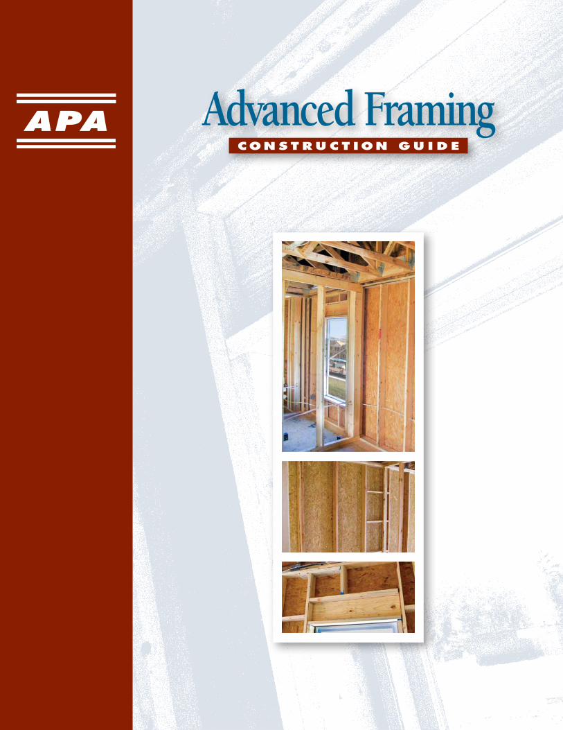
Advanced FramingCON S T R U C T ION G U I d e

Engineered wood products are a good choice for the environment. They are
manufactured for years of trouble-free, dependable use. They help reduce waste
by decreasing disposal costs and product damage. Wood is a renewable resource
that is easily manufactured into a variety of viable products.
A few facts about wood.■ We’re growing more wood every day. Forests fully cover one-third of the
United States’ and one-half of Canada’s land mass. American landowners
plant more than two billion trees every year. In addition, millions of trees seed
naturally. The forest products industry, which comprises about 15 percent of
forestland ownership, is responsible for 41 percent of replanted forest acreage.
That works out to more than one billion trees a year, or about three million trees planted every
day. This high rate of replanting accounts for the fact that each year, 27 percent more timber is
grown than is harvested. Canada’s replanting record shows a fourfold increase in the number of
trees planted between 1975 and 1990.
■ Life Cycle Assessment shows wood is the greenest building product.
A 2004 Consortium for Research on Renewable Industrial Materials
(CORRIM) study gave scientific validation to the strength of wood as a
green building product. In examining building products’ life cycles – from
extraction of the raw material to demolition of the building at the end of its
long lifespan – CORRIM found that wood was better for the environment than steel or concrete
in terms of embodied energy, global warming potential, air emissions, water emissions and solid
waste production. For the complete details of the report, visit www.CORRIM.org.
■ Manufacturing wood is energy efficient.
Wood products made up 47 percent of all
industrial raw materials manufactured in the
United States, yet consumed only 4 percent of the
energy needed to manufacture all industrial raw
materials, according to a 1987 study.
■ Good news for a healthy planet. For every ton of wood grown, a young forest
produces 1.07 tons of oxygen and absorbs 1.47 tons of carbon dioxide.
Wood: It’s the natural choice for the environment, for design and for strong,
lasting construction.
WOOdThe Natural Choice
Notice: The recommendations in this guide apply only to products that bear the APA trademark. Only products bearing the APA trademark are subject to the Association’s quality auditing program.
RATED SHEATHING
32/16SIZED FOR SPACING
EXPOSURE 1
THICKNESS 0.451 IN.
PS 1-09 C-D PRP-108
15/32 CATEGORY000
Percent of Percent of Material Production Energy Use
Wood 47 4
Steel 23 48
Aluminum 2 8
©20
12 A
PA –
TH
E EN
GIN
EERE
D W
OO
D A
SSO
CIA
TIO
N •
ALL
RIG
HTS
RES
ERVE
D. •
AN
Y C
OPY
ING
, MO
DIF
ICAT
ION
, DIS
TRIB
UTI
ON
OR
OTH
ER U
SE O
F TH
IS P
UBL
ICAT
ION
OTH
ER T
HA
N A
S EX
PRES
SLY
AUTH
ORI
ZED
BY
APA
IS P
ROH
IBIT
ED B
Y TH
E U
.S. C
OPY
RIG
HT
LAW
S.
ADVANCEDFRAMINGCONSTRUCTIONGUIDE■FORMNO.M400■©2012APA–THEENGINEEREDWOODASSOCIATION■WWW.APAWOOD.ORG2
CoNTENTs
CoMPoNENTs of AdvANCEd frAMiNg . . . . . . . . . . 4
AdvANCEd frAMiNg dEfiNEd . . . 5
AdvANTAgEs of AdvANCEd frAMiNg . . . . . . . . . . 5
Energy Efficiency . . . . . . . . . . . . . . . . . . .5Cost Effectiveness . . . . . . . . . . . . . . . . . . .6Structural Integrity . . . . . . . . . . . . . . . . . . 7Sustainability . . . . . . . . . . . . . . . . . . . . . . 7
iNCorPorATiNg AdvANCEd frAMiNg TEChNiqUEs . . . . . . . . 8
floor frAMiNg . . . . . . . . . . . . . . . 8
WAll frAMiNg . . . . . . . . . . . . . . . . .9
Stud Spacing . . . . . . . . . . . . . . . . . . . . .10Corners . . . . . . . . . . . . . . . . . . . . . . . . .10Interior Wall Intersections . . . . . . . . . . . . 11Prescriptive and Alternate
Connection Details . . . . . . . . . . . . . . . 11Headers . . . . . . . . . . . . . . . . . . . . . . . . .13Wood Structural Panel Box Headers . . . .14Openings . . . . . . . . . . . . . . . . . . . . . . . .15Blocking . . . . . . . . . . . . . . . . . . . . . . . . . 16Metal Hardware . . . . . . . . . . . . . . . . . . . 16
siNglE ToP PlATEs . . . . . . . . . . . . .17
Ceiling and Roof Framing . . . . . . . . . . . . 17Single Top Plates and Framing
Member Layout . . . . . . . . . . . . . . . . . .18
WAll shEAThiNg . . . . . . . . . . . . . .18
Wind Resistance and Wall Assemblies . . .18Wall Bracing . . . . . . . . . . . . . . . . . . . . . .20
MorE iNforMATioN . . . . . . . . . . .21
Engineered Wood Construction Systems . . . . . . . . . . . . . . 21
Building Codes Referenced in this Guide . . . . . . . . . . . . . . . . . . . .22
Additional References . . . . . . . . . . . . . . .22Acknowledgements . . . . . . . . . . . . . . . . .22About APA . . . . . . . . . . . . . . . . . . . . . . .23
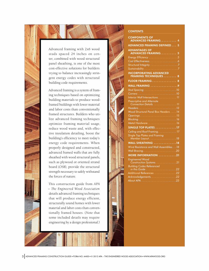
Advanced framing with 2x6 wood
studs spaced 24 inches on cen-
ter, combined with wood structural
panel sheathing, is one of the most
cost-effective solutions for builders
trying to balance increasingly strin-
gent energy codes with structural
building code requirements.
Advanced framing is a system of fram-
ing techniques based on optimizing
building materials to produce wood-
framed buildings with lower material
and labor costs than conventionally
framed structures. Builders who uti-
lize advanced framing techniques
optimize framing material usage,
reduce wood waste and, with effec-
tive insulation detailing, boost the
building’s efficiency to meet today’s
energy code requirements. When
properly designed and constructed,
advanced framed walls that are fully
sheathed with wood structural panels,
such as plywood or oriented strand
board (OSB), provide the structural
strength necessary to safely withstand
the forces of nature.
This construction guide from APA
– The Engineered Wood Association
details advanced framing techniques
that will produce energy efficient,
structurally sound homes with lower
material and labor costs than conven-
tionally framed houses. (Note that
some included details may require
engineering by a design professional.)
ADVANCEDFRAMINGCONSTRUCTIONGUIDE■FORMNO.M400■©2012APA–THEENGINEEREDWOODASSOCIATION■WWW.APAWOOD.ORG3
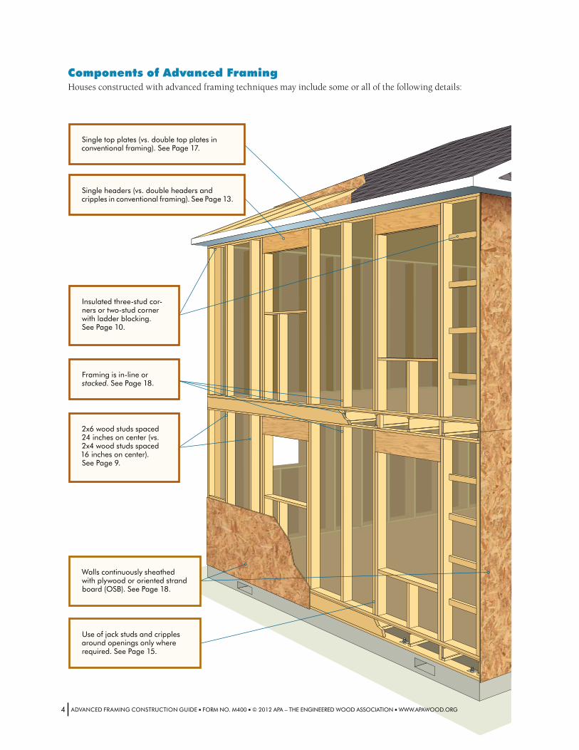
Singletopplates(vs.doubletopplatesinconventionalframing).SeePage17.
Components of Advanced FramingHouses constructed with advanced framing techniques may include some or all of the following details:
Framingisin-lineorstacked.SeePage18.
Insulatedthree-studcor-nersortwo-studcornerwithladderblocking.SeePage10.
Useofjackstudsandcripplesaroundopeningsonlywhererequired.SeePage15.
Singleheaders(vs.doubleheadersandcripplesinconventionalframing).SeePage13.
2x6woodstudsspaced24inchesoncenter(vs.2x4woodstudsspaced16inchesoncenter).SeePage9.
Wallscontinuouslysheathedwithplywoodororientedstrandboard(OSB).SeePage18.
ADVANCEDFRAMINGCONSTRUCTIONGUIDE■FORMNO.M400■©2012APA–THEENGINEEREDWOODASSOCIATION■WWW.APAWOOD.ORG4
Advanced Framing definedAdvanced framing is a system of construction framing techniques designed to optimize material usage and increase
energy efficiency. Structures built with advanced framing techniques are more resource efficient and offer more space
for cavity insulation than similar structures built with conventional framing.
Conventional framing, the industry standard for framing residential construction, typically consists of 2x4 or 2x6
wood framing spaced 16 inches on center, double top plates, three-stud corners, multiple jack studs, double or triple
headers, unnecessary cripple studs and other redundant members.
Advanced framing reduces the unnecessary structural redundancies inherent in conventional framing by placing
framing members only where they’re needed. The most commonly adopted advanced framing technique is 2x6 wood
framing spaced 24 inches on center. Other commonly used techniques include single top plates, two-stud corners, sin-
gle headers, minimal use of jack studs and cripples, and the elimination of redundant studs and unnecessary blocking
and bridging. Although some advanced framing techniques can be adopted independently, the greatest savings – in
both cost of construction and energy – will be realized when the system is applied holistically.
Advanced framing – also known as optimum value engineering (OVE) – was developed by the NAHB Research Center,
an independent subsidiary of the National Association of Home Builders (NAHB), in the 1970s for the purpose of opti-
mizing material usage while maintaining structural integrity. Today, growing interest in energy conservation is leading
more and more builders to adopt advanced framing techniques.
APA recommends that you consult your local building official early in the design phase to verify and obtain acceptance
of 24-inch framing techniques in your jurisdiction.
Advantages of Advanced FramingAdvanced framing produces energy efficient, structurally sound homes with lower material and labor costs than con-
ventionally framed houses. The key advantages of advanced framing include:
Energy EfficiencyAdvanced framing is a proven method
for cost-effectively meeting energy
code requirements. By maximizing
space for cavity insulation and min-
imizing the potential for insulation
voids, advanced framing delivers sig-
nificant energy performance and cost
savings for the builder.
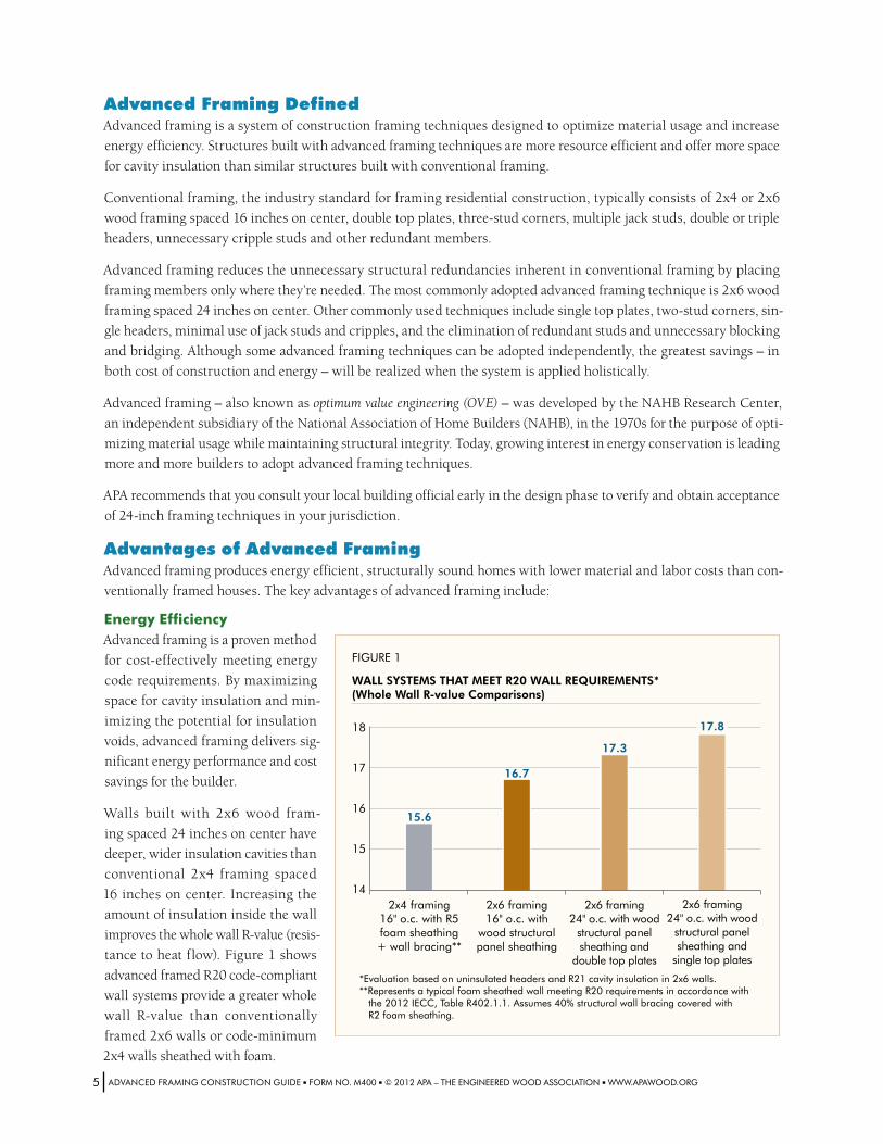
Walls built with 2x6 wood fram-
ing spaced 24 inches on center have
deeper, wider insulation cavities than
conventional 2x4 framing spaced
16 inches on center. Increasing the
amount of insulation inside the wall
improves the whole wall R-value (resis-
tance to heat flow). Figure 1 shows
advanced framed R20 code-compliant
wall systems provide a greater whole
wall R-value than conventionally
framed 2x6 walls or code-minimum
2x4 walls sheathed with foam.
FIGURE 1
WALL SYSTEMS THAT MEET R20 WALL REQUIREMENTS*(Whole Wall R-value Comparisons)
17.3
17.8
2x4 framing16" o.c. with R5 foam sheathing + wall bracing**
*Evaluation based on uninsulated headers and R21 cavity insulation in 2x6 walls.**Represents a typical foam sheathed wall meeting R20 requirements in accordance with the 2012 IECC, Table R402.1.1. Assumes 40% structural wall bracing covered with R2 foam sheathing.
14
15
16
17
18
15.6
2x6 framing16" o.c. with
wood structural panel sheathing
2x6 framing24" o.c. with wood
structural panel sheathing and
double top plates
2x6 framing24" o.c. with wood
structural panel sheathing and
single top plates
16.7
ADVANCEDFRAMINGCONSTRUCTIONGUIDE■FORMNO.M400■©2012APA–THEENGINEEREDWOODASSOCIATION■WWW.APAWOOD.ORG5
In addition to maximizing space for cavity insulation, advanced framing simplifies the installation of insulation and
air sealing. Conventional framing can leave voids and small cavities in the framing at wall intersections and corners
that can be difficult to insulate and seal effectively. By installing fewer framing members, it is easier for the builder to
apply complete insulation coverage and achieve a tighter building envelope.
As energy codes have become increasingly stringent, advanced framing has grown more popular in climate zones where
high prescriptive wall R-values are mandated or desired. While framing with 2x6 studs spaced 16 inches on center is
already common in many northern states with more restrictive energy demands, increasing stud spacing to 24 inches
on center, insulating effectively, and fully sheathing with wood structural panels, such as plywood or oriented strand
board (OSB), allows builders to cost-effectively balance energy and structural code requirements.
The ENERGY STAR® program was developed by the U.S. Environmental Protection Agency to pro-
mote the use of energy efficient products and practices. Advanced framing can help builders meet
the requirements necessary to earn the ENERGY STAR label for new homes. Advanced framing tech-
niques qualify as Reduced Thermal Bridging under section 4.4.5 of the Thermal Enclosure System
Rater Checklist (ver. 3, rev. 5). These techniques must be incorporated to earn the ENERGY STAR
label when using section 4.4.5 of the Checklist.
The framing width and spacing requirements for the
Thermal Enclosure System Rater Checklist vary by
climate zone:
■■16 inches on center (minimum) spacing if using 2x4 framing
■■24 inches on center (minimum) spacing if using 2x6 framing in colder climates (zones 5-8)
■■16 inches on center (minimum) spacing if using 2x6 framing in warmer climates (zones 1-4)
In addition, the following advanced framing techniques
must also be incorporated to meet the thermal bridging
requirements of the checklist:
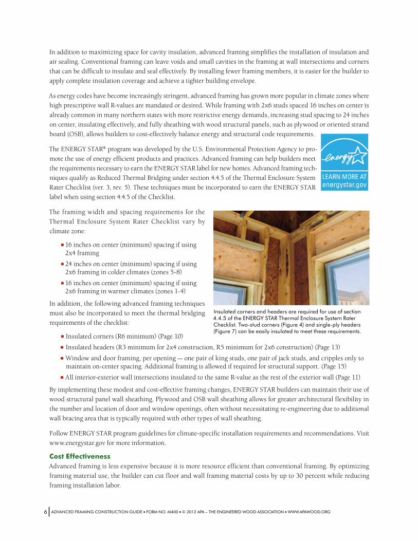
■■ Insulated corners (R6 minimum) (Page 10)
■■ Insulated headers (R3 minimum for 2x4 construction, R5 minimum for 2x6 construction) (Page 13)
■■ Window and door framing, per opening — one pair of king studs, one pair of jack studs, and cripples only to maintain on-center spacing. Additional framing is allowed if required for structural support. (Page 15)
■■ All interior-exterior wall intersections insulated to the same R-value as the rest of the exterior wall (Page 11)
By implementing these modest and cost-effective framing changes, ENERGY STAR builders can maintain their use of
wood structural panel wall sheathing. Plywood and OSB wall sheathing allows for greater architectural flexibility in
the number and location of door and window openings, often without necessitating re-engineering due to additional
wall bracing area that is typically required with other types of wall sheathing.
Follow ENERGY STAR program guidelines for climate-specific installation requirements and recommendations. Visit
www.energystar.gov for more information.
Cost EffectivenessAdvanced framing is less expensive because it is more resource efficient than conventional framing. By optimizing
framing material use, the builder can cut floor and wall framing material costs by up to 30 percent while reducing
framing installation labor.
ADVANCEDFRAMINGCONSTRUCTIONGUIDE■FORMNO.M400■©2012APA–THEENGINEEREDWOODASSOCIATION■WWW.APAWOOD.ORG6
Insulatedcornersandheadersarerequiredforuseofsection4.4.5oftheENERGYSTARThermalEnclosureSystemRaterChecklist.Two-studcorners(Figure4)andsingle-plyheaders(Figure7)canbeeasilyinsulatedtomeettheserequirements.
Advanced framing can help to increase the efficiency of other trades as well; more space between framing members
means fewer studs for plumbers and electricians to drill through and fewer cavities for insulators to fill. Additional
savings may result from a reduction in construction waste and dumpster costs.
Structural IntegrityThe advanced framing method combined with continuous wood structural panel sheathing delivers builders with an
optimal solution: a cost-effective framing system that will produce more energy efficient homes without compromis-
ing the strength or durability of the structure.
Where builders align the vertical framing members under the roof trusses or rafters, a direct load path is created in
which compression and tension loads are directly transferred through the vertical framing members (Figure 13). The
result is a stronger structure with fewer framing members subject to stresses.
When properly constructed, advanced framed walls that are fully sheathed with wood structural panels provide the
structure with the strength to safely withstand design loads. Of all the available wall sheathing products, wood struc-
tural panels are afforded the most flexibility within the building code for 24-inch on center wall framing, providing
solutions to code limitations that restrict most other wall bracing materials and popular siding products.
Wall bracing solutions: Due to their superior structural performance, continuous sheathing with wood structural
panels is code-recognized as wall bracing for studs spaced up to 24 inches on center. Most other wall bracing meth-
ods, including let-in bracing and some alternative panel products, are limited by the code to 16-inch on center framing.
(Refer to building code requirements or manufacturer ICC-ES reports for more information.)
Siding attachment solutions: The most common and cost-effective grades of vinyl siding require fastening into studs
every 16 inches. However, the nailbase capabilities of a continuously sheathed wood structural panel wall allow the
use of these siding products with 24-inch on center framing because the sheathing also serves as a base for fastener
attachment between studs. This saves the builder the potential added cost and hassle of having to change siding prod-
ucts. (Refer to siding manufacturer ICC-ES reports and APA Technical Topics: Wood Structural Panels Used as Nailable
Sheathing, Form TT-109, for more information.)
Wall sheathing systems that incorporate plywood and OSB offer the best balance of energy efficiency, structural perfor-
mance and affordability. Wood sheathed walls allow for easy integration of windows into the weather resistive barrier
and are simple to insulate with all types of cavity insulation for high R-values. Plywood and OSB sheathing also provides
shear strength to resist the forces of nature. For more information, refer to APA’s Introduction to Wall Bracing, Form F430.
SustainabilityWood construction systems such as advanced framing techniques fit well with green building strategies. Wood is a
renewable resource that is manufactured in efficient processes that require less energy than is required for other build-
ing materials, such as steel and concrete.
Wood-frame construction that utilizes advanced framing techniques delivers even greater environmental dividends
by optimizing material usage and reducing construction waste. Many of the construction techniques presented in
this guide may be eligible for points under the leading green building standards and guidelines, such as the National
Green Building Standard™ (ICC 700-2008) and the U.S. Green Building Council LEED® for Homes Rating System.
The ICC 700, established by the National Association of Home Builders (NAHB) and the International Code Council
(ICC) in 2007, awards points to builders that incorporate green practices into single- and multifamily home construction
and residential remodeling projects. This includes the implementation of building-code-compliant advanced framing
techniques in design and construction. ICC 700 Section 601.2 awards 3 points for each qualifying advanced framing
technique implemented that exceeds 80 percent usage in the building, and 9 points maximum if the techniques are
used for all floor, wall and/or roof framing. For more information, visit www.nahbgreen.org/NGBS.
ADVANCEDFRAMINGCONSTRUCTIONGUIDE■FORMNO.M400■©2012APA–THEENGINEEREDWOODASSOCIATION■WWW.APAWOOD.ORG7

Incorporating Advanced Framing TechniquesBecause significant changes in framing practices, such as eliminating double top plates in favor of single top plates,
may initially require increased effort at the design stage and oversight during construction, many builders elect to
incorporate advanced framing in stages rather than all at once. If increased energy-efficiency is a primary reason for
converting to advanced framing, the following steps are recommended. Note that not all advanced framing techniques
are required; builders may elect to incorporate fewer than all four steps depending on their circumstances.
1. Switch to 2x6 studs to increase cavity insulation depth and meet R20 energy code requirements. (Especially important in colder climate zones.)
2. Where permitted by structural code requirements, change the wall framing module from 16 inches on center to 24 inches on center to reduce framing costs. Retain the use of double top plates to avoid in-line, or stack, framing alignment requirements.
3. Incorporate intersecting wall techniques and energy efficient corners, such as three-stud cor-ners and ladder junctions, that allow for greater insulation volume. Implement energy-efficient headers and limited framing around openings.
4. Eliminate double top plates. Because this step requires vertical framing alignment, including 24-inch on cen-ter floor and roof framing as well as non-industry standard stud lengths which may be difficult to source, it is often the last technique builders consider. For these reasons, many builders elect to retain double top plates.
Whatever techniques are selected, it is important that the advanced framing details are clearly specified on the architec-
tural plans when submitted to the building department. Note that if framing crews are unfamiliar with advanced framing,
additional onsite supervision and quality control oversight should be planned while framers learn these new techniques.
Floor FramingFloor framing is generally subject to home design, foundation requirements and customer expectations, but substan-
tial resource and cost savings can still be realized when the principles of advanced framing are applied. To achieve
optimum resource efficiency:
1. Specify engineered wood floor joists, such as I-joists, structural composite lumber (SCL), and/or glulam at 24 inches on center.
2. Maximize member spans between supports.
Specifying engineered wood products, such as I-joists, SCL, and/or glulam, instead of dimension lumber for band
joists and floor beams will produce substantially greater spans between foundation elements. Maximizing member
spans will increase construction efficiency while reducing construction costs. Additional cost savings will result from
reduced cutoff waste generated from a reduced number of framing members.
Spacing engineered wood floor joists 24 inches on center will reduce the number of joists required by about 30 percent
as compared to conventional 16-inch floor joist spacing. Note that deeper or larger joists may be required. Some floor
serviceability characteristics, such as floor vibration, may also need to be considered. For information on minimizing
floor vibration, refer to APA Technical Note: Minimizing Floor Vibration by Design and Retrofit, Form E710.
Ladderjunctionsatinterior-exteriorwallintersections(Figure5)producewallcavitiesthatcanbeeasilyinsulatedtohelpbuildersearntheENERGYSTAR®labelfornewhomes.
ADVANCEDFRAMINGCONSTRUCTIONGUIDE■FORMNO.M400■©2012APA–THEENGINEEREDWOODASSOCIATION■WWW.APAWOOD.ORG8
Engineered wood I-joists, SCL and glulam members are commonly available in a variety of depths to provide cost-effi-
cient floor framing. Specifying I-joist floor systems between finished floors will typically allow for the installation of
plumbing, electrical and mechanical services within the floor frame cavity, eliminating the need for dropped ceilings.
When installing floor sheathing, keep in mind that many of today’s home buyers expect stiffer, more solid feeling
floors. Consider using thicker panels with 24-inch on center floor framing to enhance floor stiffness. The extra cost
of thicker sheathing will often be offset by the lower cost of floor framing. Refer to flooring manufacturer for installa-
tion recommendations for 24-inch on center floor framing systems.
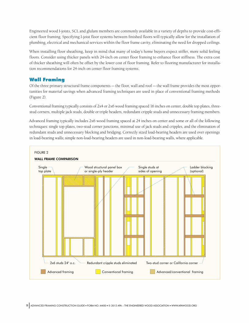
Wall FramingOf the three primary structural frame components — the floor, wall and roof — the wall frame provides the most oppor-
tunities for material savings when advanced framing techniques are used in place of conventional framing methods
(Figure 2).
Conventional framing typically consists of 2x4 or 2x6 wood framing spaced 16 inches on center, double top plates, three-
stud corners, multiple jack studs, double or triple headers, redundant cripple studs and unnecessary framing members.
Advanced framing typically includes 2x6 wood framing spaced at 24 inches on center and some or all of the following
techniques: single top plates, two-stud corner junctions, minimal use of jack studs and cripples, and the elimination of
redundant studs and unnecessary blocking and bridging. Correctly sized load-bearing headers are used over openings
in load-bearing walls; simple non-load-bearing headers are used in non-load-bearing walls, where applicable.
FIGURE 2
WALL FRAME COMPARISON
2x6 studs 24" o.c. Redundant cripple studs eliminated
Advanced framing Advanced/conventional framingConventional framing
Single studs atsides of opening
Ladder blocking(optional)
Two-stud corner or California corner
Singletop plate
Wood structural panel boxor single-ply header
ADVANCEDFRAMINGCONSTRUCTIONGUIDE■FORMNO.M400■©2012APA–THEENGINEEREDWOODASSOCIATION■WWW.APAWOOD.ORG9
Wall frame construction that utilizes
all available advanced framing tech-
niques, including single top plates, can
realize up to a 30 percent reduction in
framing material used in the wall.
In addition to improving framing effi-
ciency, advanced framing also boosts
whole wall R-value (resistance to heat
flow) by maximizing space for cavity
insulation. When advanced framing
techniques are employed — including
insulated headers — the reduction in
the amount of framing materials can
result in up to 12 percent more insu-
lated space within the exterior wall.
Stud SpacingFraming members are conventionally
spaced 16 inches on center. Advanced
framing methods increase member
spacing, typically to 24 inches on cen-
ter (Figure 2). This stud spacing fits
well with all commonly used sheath-
ing, insulation and finish materials.
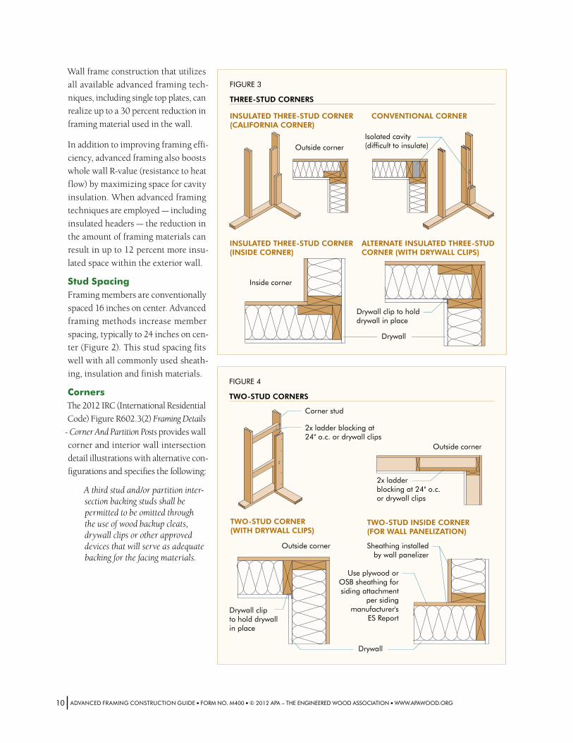
CornersThe 2012 IRC (International Residential
Code) Figure R602.3(2) Framing Details
- Corner And Partition Posts provides wall
corner and interior wall intersection
detail illustrations with alternative con-
figurations and specifies the following:
A third stud and/or partition inter-section backing studs shall be permitted to be omitted through the use of wood backup cleats, drywall clips or other approved devices that will serve as adequate backing for the facing materials.
FIGURE 4
TWO-STUD CORNERS
Corner stud
2x ladder blocking at24" o.c. or drywall clips
TWO-STUD INSIDE CORNER(FOR WALL PANELIZATION)
Outside corner
Outside corner Sheathing installedby wall panelizer
2x ladderblocking at 24" o.c.or drywall clips
TWO-STUD CORNER(WITH DRYWALL CLIPS)
Drywall clipto hold drywallin place
Use plywood or OSB sheathing for siding attachment
per siding manufacturer's
ES Report
Drywall
FIGURE 3
THREE-STUD CORNERS
Isolated cavity(difficult to insulate)
INSULATED THREE-STUD CORNER(CALIFORNIA CORNER)
CONVENTIONAL CORNER
ALTERNATE INSULATED THREE-STUDCORNER (WITH DRYWALL CLIPS)
INSULATED THREE-STUD CORNER(INSIDE CORNER)
Inside corner
Outside corner
Drywall clip to hold drywall in place
Drywall
ADVANCEDFRAMINGCONSTRUCTIONGUIDE■FORMNO.M400■©2012APA–THEENGINEEREDWOODASSOCIATION■WWW.APAWOOD.ORG10
Advanced framing wall corners can include insulated three-stud corners (sometimes referred to as California corners)
as shown in Figure 3, or two-stud corner junctions with ladder blocking, drywall clips, or an alternative means of
supporting interior or exterior finish materials as shown in Figure 4. These techniques eliminate the isolated cavity
found in conventional three-stud corners, making it easier to install insulation and providing more cavity insulation
space at exterior insulated wall corners.
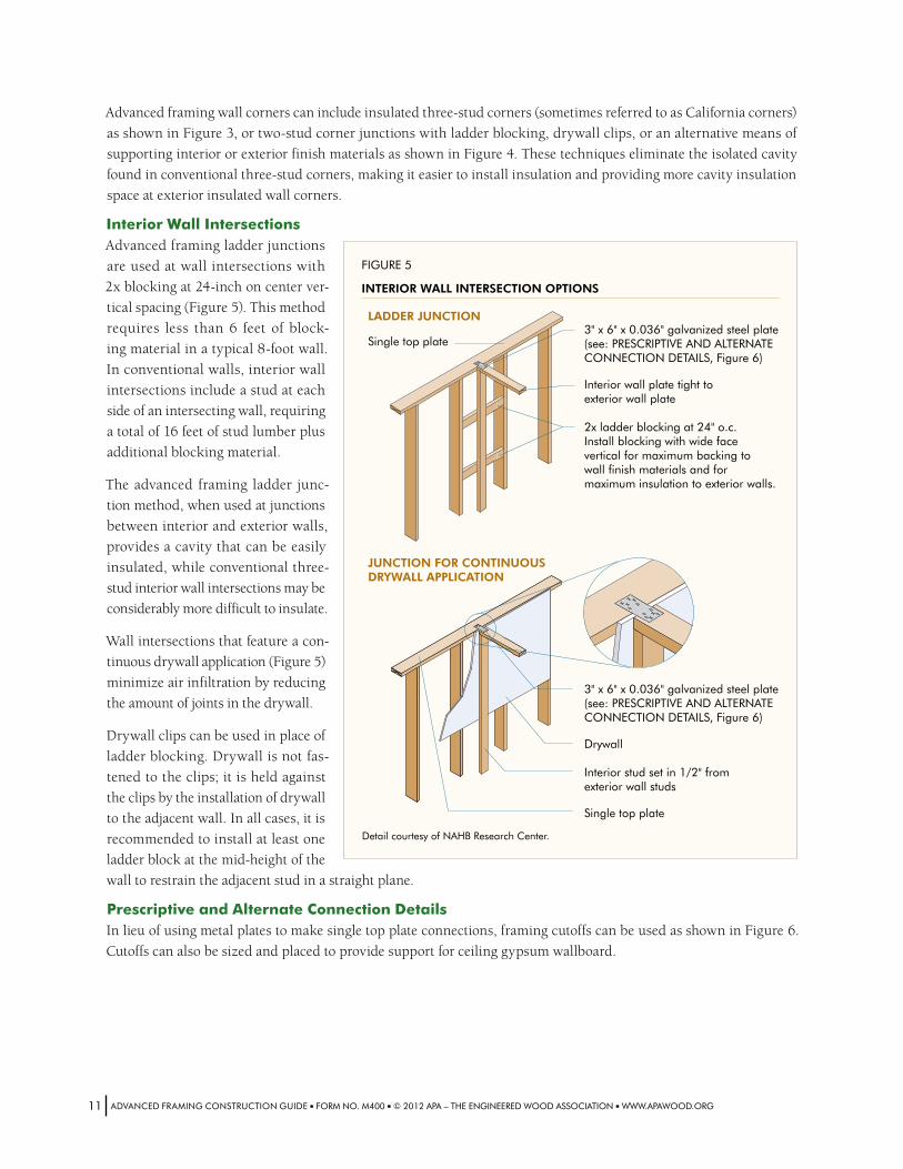
Interior Wall IntersectionsAdvanced framing ladder junctions
are used at wall intersections with
2x blocking at 24-inch on center ver-
tical spacing (Figure 5). This method
requires less than 6 feet of block-
ing material in a typical 8-foot wall.
In conventional walls, interior wall
intersections include a stud at each
side of an intersecting wall, requiring
a total of 16 feet of stud lumber plus
additional blocking material.
The advanced framing ladder junc-
tion method, when used at junctions
between interior and exterior walls,
provides a cavity that can be easily
insulated, while conventional three-
stud interior wall intersections may be
considerably more difficult to insulate.
Wall intersections that feature a con-
tinuous drywall application (Figure 5)
minimize air infiltration by reducing
the amount of joints in the drywall.
Drywall clips can be used in place of
ladder blocking. Drywall is not fas-
tened to the clips; it is held against
the clips by the installation of drywall
to the adjacent wall. In all cases, it is
recommended to install at least one
ladder block at the mid-height of the
wall to restrain the adjacent stud in a straight plane.
Prescriptive and Alternate Connection DetailsIn lieu of using metal plates to make single top plate connections, framing cutoffs can be used as shown in Figure 6.
Cutoffs can also be sized and placed to provide support for ceiling gypsum wallboard.
FIGURE 5
INTERIOR WALL INTERSECTION OPTIONS
3" x 6" x 0.036" galvanized steel plate(see: PRESCRIPTIVE AND ALTERNATECONNECTION DETAILS, Figure 6)
Interior wall plate tight toexterior wall plate
2x ladder blocking at 24" o.c.Install blocking with wide facevertical for maximum backing towall finish materials and formaximum insulation to exterior walls.
3" x 6" x 0.036" galvanized steel plate(see: PRESCRIPTIVE AND ALTERNATECONNECTION DETAILS, Figure 6)
Drywall
Interior stud set in 1/2" fromexterior wall studs
Single top plate
LADDER JUNCTION
JUNCTION FOR CONTINUOUSDRYWALL APPLICATION
Detail courtesy of NAHB Research Center.
Single top plate
ADVANCEDFRAMINGCONSTRUCTIONGUIDE■FORMNO.M400■©2012APA–THEENGINEEREDWOODASSOCIATION■WWW.APAWOOD.ORG11
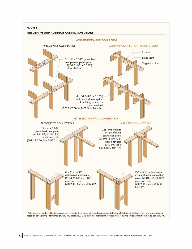
FIGURE 6
PRESCRIPTIVE AND ALTERNATE CONNECTION DETAILS
2x scab
Splice joint
Single top plate
3" x 12" x 0.036" galvanizedsteel plate at plate splice.(12) 8d (2-1/2" x 0.113")nails each side.*
3" x 6" x 0.036"galvanized steel plate.
(6) 8d (2-1/2" x 0.113")nails each side
(2012 IRC Section R602.3.2).
3" x 6" x 0.036"galvanized steel plate.(6) 8d (2-1/2" x 0.113")nails each side(2012 IRC Section R602.3.2).
2x6 lumber splicein lieu of metal
connection plate.(2) 10d (3" x 0.128")
nails each side(2012 IRC Table
R602.3(1), Item 19).
2x4 or 2x6 lumber splicein lieu of metal connectionplate. (2) 10d (3" x 0.128")nails each side(2012 IRC Table R602.3(1),Item 19).
(8) 16d (3-1/2" x 0.135")nails each side of splice.
No splitting of scab orplate permitted
(2012 IRC Table R602.3(1), Item 14).
LONGITUDINAL TOP PLATE SPLICE
INTERSECTING WALL CONNECTION
PRESCRIPTIVE CONNECTION
PRESCRIPTIVE CONNECTION
ALTERNATE CONNECTION: SPLICE AT STUD
ALTERNATE CONNECTION
*Plate size and number of fasteners required is greater than prescriptive code requirements for top plate butt-joint splices. This recommendation is based on equivalent performance of 2012 IRC Table R602.3(1), Item 14. Intersecting wall segment top plate splice connections are as per 2012 IRC.
ADVANCEDFRAMINGCONSTRUCTIONGUIDE■FORMNO.M400■©2012APA–THEENGINEEREDWOODASSOCIATION■WWW.APAWOOD.ORG12
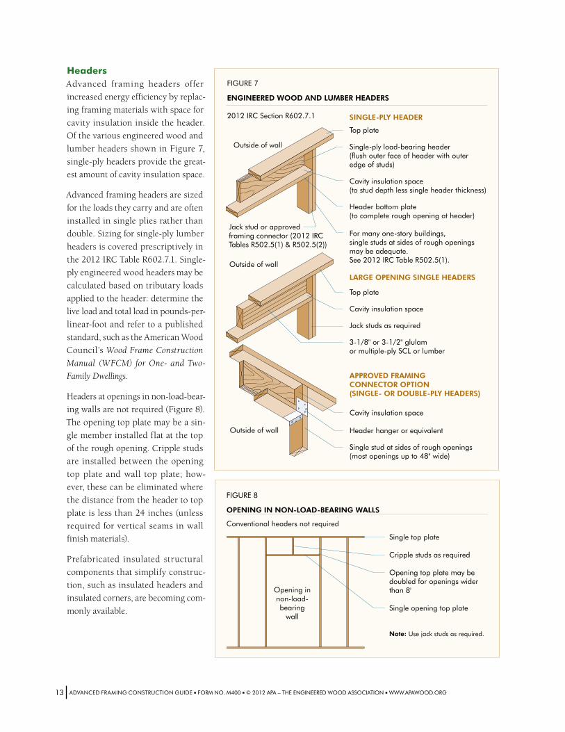
HeadersAdvanced framing headers offer
increased energy efficiency by replac-
ing framing materials with space for
cavity insulation inside the header.
Of the various engineered wood and
lumber headers shown in Figure 7,
single-ply headers provide the great-
est amount of cavity insulation space.
Advanced framing headers are sized
for the loads they carry and are often
installed in single plies rather than
double. Sizing for single-ply lumber
headers is covered prescriptively in
the 2012 IRC Table R602.7.1. Single-
ply engineered wood headers may be
calculated based on tributary loads
applied to the header: determine the
live load and total load in pounds-per-
linear-foot and refer to a published
standard, such as the American Wood
Council’s Wood Frame Construction
Manual (WFCM) for One- and Two-
Family Dwellings.
Headers at openings in non-load-bear-
ing walls are not required (Figure 8).
The opening top plate may be a sin-
gle member installed flat at the top
of the rough opening. Cripple studs
are installed between the opening
top plate and wall top plate; how-
ever, these can be eliminated where
the distance from the header to top
plate is less than 24 inches (unless
required for vertical seams in wall
finish materials).
Prefabricated insulated structural
components that simplify construc-
tion, such as insulated headers and
insulated corners, are becoming com-
monly available.
FIGURE 7
ENGINEERED WOOD AND LUMBER HEADERS
2012 IRC Section R602.7.1
Top plate
Single-ply load-bearing header(flush outer face of header with outeredge of studs)
Cavity insulation space(to stud depth less single header thickness)
Header bottom plate(to complete rough opening at header)
For many one-story buildings,single studs at sides of rough openingsmay be adequate.See 2012 IRC Table R502.5(1).
Outside of wall
Outside of wall
Outside of wall
Top plate
Cavity insulation space
Jack studs as required
3-1/8" or 3-1/2" glulamor multiple-ply SCL or lumber
LARGE OPENING SINGLE HEADERS
SINGLE-PLY HEADER
APPROVED FRAMINGCONNECTOR OPTION(SINGLE- OR DOUBLE-PLY HEADERS)
Cavity insulation space
Header hanger or equivalent
Single stud at sides of rough openings(most openings up to 48" wide)
Jack stud or approved framing connector (2012 IRC Tables R502.5(1) & R502.5(2))
FIGURE 8
OPENING IN NON-LOAD-BEARING WALLS
Opening innon-load-bearing
wall
Conventional headers not required
Single top plate
Cripple studs as required
Opening top plate may be doubled for openings wider than 8'
Single opening top plate
Note: Use jack studs as required.
ADVANCEDFRAMINGCONSTRUCTIONGUIDE■FORMNO.M400■©2012APA–THEENGINEEREDWOODASSOCIATION■WWW.APAWOOD.ORG13
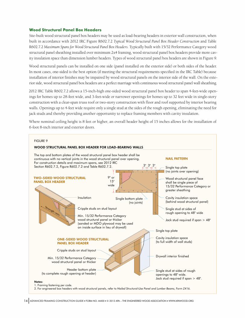
FIGURE 9
WOOD STRUCTURAL PANEL BOX HEADER FOR LOAD-BEARING WALLS
The top and bottom plates of the wood structural panel box header shall becontinuous with no vertical joints in the wood structural panel over opening.For construction details and maximum spans, see 2012 IRCSection R602.7.2, Figure R602.7.2 and Table R602.7.2.
NAIL PATTERN
TWO-SIDED WOOD STRUCTURALPANEL BOX HEADER
ONE-SIDED WOOD STRUCTURALPANEL BOX HEADER
3" 3" 3"
9" or15"
wide
Single bottom plate(no joints)
Single top plate(no joints over opening)
Wood structural panel faceshall be single piece of15/32 Performance Category orgreater sheathing
Cavity insulation space(behind wood structural panel)
Single stud at sides ofrough opening to 48" wide
Jack stud required if span > 48"
Single top plate
Cavity insulation space(to full width of wall studs)
Drywall interior finished
Single stud at sides of roughopenings to 48" wide.Jack stud required if span > 48".
Cripple studs on stud layout
Min. 15/32 Performance Categorywood structural panel or thicker(sanded or MDO plywood may be usedon inside surface in lieu of drywall)
Cripple studs on stud layout
Min. 15/32 Performance Categorywood structural panel or thicker
Header bottom plate(to complete rough opening at header)
Strength axis
Insulation
Notes: 1. Framing fastening per code.2. For engineered box headers with wood structural panels, refer to Nailed Structural-Use Panel and Lumber Beams, Form Z416.
Wood Structural Panel Box HeadersSite-built wood structural panel box headers may be used as load-bearing headers in exterior wall construction, when
built in accordance with 2012 IRC Figure R602.7.2 Typical Wood Structural Panel Box Header Construction and Table
R602.7.2 Maximum Spans for Wood Structural Panel Box Headers. Typically built with 15/32 Performance Category wood
structural panel sheathing installed over minimum 2x4 framing, wood structural panel box headers provide more cav-
ity insulation space than dimension lumber headers. Types of wood structural panel box headers are shown in Figure 9.
Wood structural panels can be installed on one side (panel installed on the exterior side) or both sides of the header.
In most cases, one-sided is the best option (if meeting the structural requirements specified in the IRC Table) because
installation of interior finishes may be impaired by wood structural panels on the interior side of the wall. On the exte-
rior side, wood structural panel box headers are a perfect marriage with continuous wood structural panel wall sheathing.
2012 IRC Table R602.7.2 allows a 15-inch-high one-sided wood structural panel box header to span 4-feet-wide open-
ings for homes up to 28-feet wide, and 3-feet-wide or narrower openings for homes up to 32 feet wide in single-story
construction with a clear-span truss roof or two-story construction with floor and roof supported by interior bearing
walls. Openings up to 4-feet wide require only a single stud at the sides of the rough opening, eliminating the need for
jack studs and thereby providing another opportunity to replace framing members with cavity insulation.
Where nominal ceiling height is 8 feet or higher, an overall header height of 15 inches allows for the installation of
6-foot 8-inch interior and exterior doors.
ADVANCEDFRAMINGCONSTRUCTIONGUIDE■FORMNO.M400■©2012APA–THEENGINEEREDWOODASSOCIATION■WWW.APAWOOD.ORG14
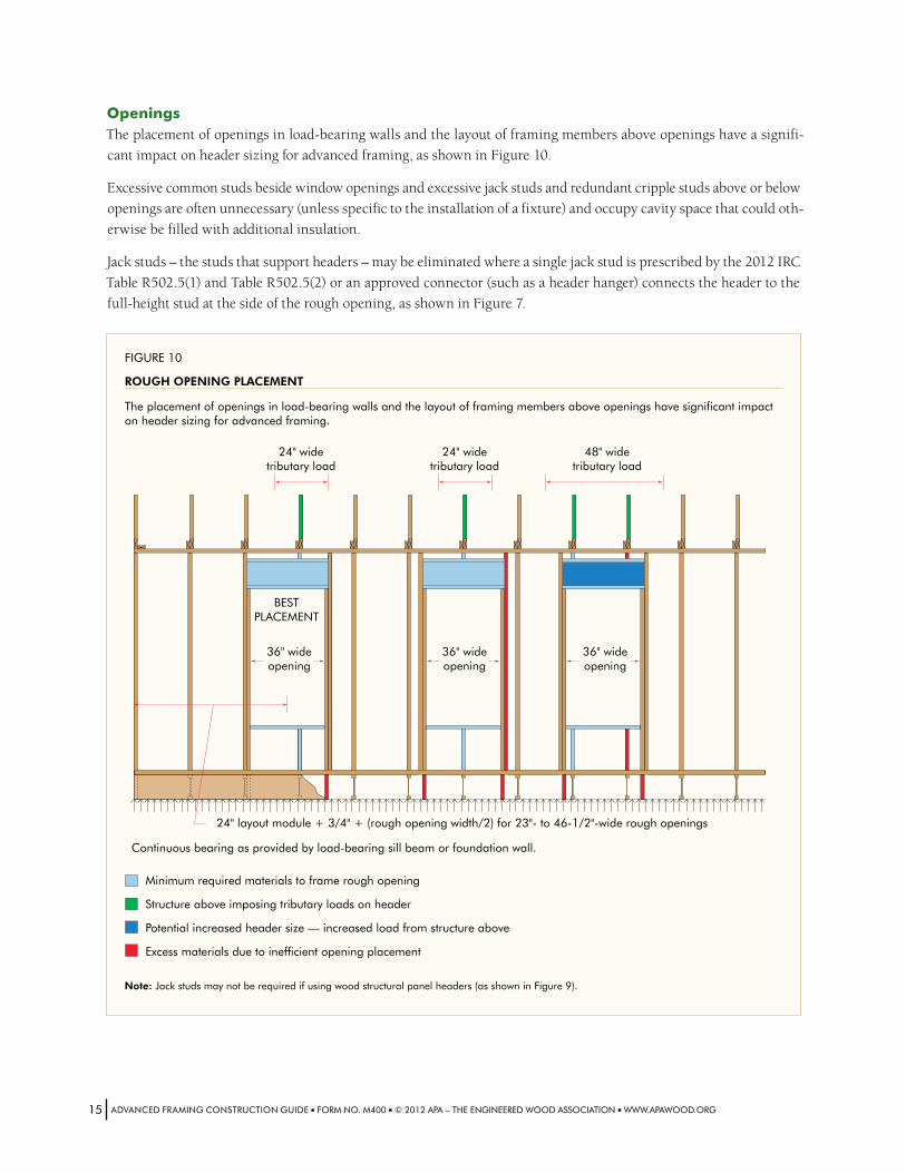
OpeningsThe placement of openings in load-bearing walls and the layout of framing members above openings have a signifi-
cant impact on header sizing for advanced framing, as shown in Figure 10.
Excessive common studs beside window openings and excessive jack studs and redundant cripple studs above or below
openings are often unnecessary (unless specific to the installation of a fixture) and occupy cavity space that could oth-
erwise be filled with additional insulation.
Jack studs – the studs that support headers – may be eliminated where a single jack stud is prescribed by the 2012 IRC
Table R502.5(1) and Table R502.5(2) or an approved connector (such as a header hanger) connects the header to the
full-height stud at the side of the rough opening, as shown in Figure 7.
FIGURE 10
ROUGH OPENING PLACEMENT
24" widetributary load
36" wideopening
36" wideopening
36" wideopening
BESTPLACEMENT
24" widetributary load
48" widetributary load
The placement of openings in load-bearing walls and the layout of framing members above openings have significant impact on header sizing for advanced framing.
Minimum required materials to frame rough opening
Structure above imposing tributary loads on header
Potential increased header size — increased load from structure above
Excess materials due to inefficient opening placement
Continuous bearing as provided by load-bearing sill beam or foundation wall.
Note: Jack studs may not be required if using wood structural panel headers (as shown in Figure 9).
24" layout module + 3/4" + (rough opening width/2) for 23"- to 46-1/2"-wide rough openings
ADVANCEDFRAMINGCONSTRUCTIONGUIDE■FORMNO.M400■©2012APA–THEENGINEEREDWOODASSOCIATION■WWW.APAWOOD.ORG15

The number of full-height studs required at the sides of an opening is not specified in the 2012 IRC, but it is included
in The Wood Frame Construction Manual (WFCM) for One- and Two-Family Dwellings, 2012 Edition.
2012 WFCM 3.4.1.4.2 Full height studs… The minimum number of full height studs at each end of the header shall not be less than half the number of studs replaced by the opening, in accordance with Table 3.23C.
Exception: The minimum number of full height studs at each end of the header shall be permitted to be reduced in accor-dance with Table 3.23D...
Table 3.23D of the 2012 WFCM specifies that, for areas with up to 150 mph (3 second gust) design wind velocity, a sin-
gle full-height stud is required at each end of a header above openings of up to 48-inches wide when studs are spaced
24 inches on center, subject to stud length and grade limitations.
BlockingAdvanced framing techniques minimize blocking and
bridging except where necessary, such as when support-
ing braced wall panel joints. Where additional framing
elements are required for the installation of fixtures or
the reinforcement of finish materials, blocking between
studs or besides studs provides more space for insulation
inside the wall cavity than the installation of additional
full-height studs.
2x horizontal blocking (installed perpendicular to the
studs) can be oriented with either the edge against the
sheathing/drywall or the wide face vertical against the
sheathing/drywall. Install the blocking with the wide face
vertical against the sheathing/drywall for maximum back-
ing to wall finish materials and minimal intrusion into
insulatable cavity.
Metal HardwareStraps and anchors are often required in the structural frame design to resist uplift and lateral wind loads or seismic
forces, but metal hardware causes thermal bridging. A thermal bridge occurs when heat is transferred through a build-
ing component at a higher rate than the transfer through the surrounding envelope. Since the thermal conductivity of
metal is hundreds of times greater than that of wood, the reduction or elimination of metal straps and anchors from
the thermal envelope (as permitted by structural requirements) can translate to reduced heat loss.
When framing members are vertically aligned to create a direct load path – in which loads are directly transferred
through the framing members (Figure 13) – the studs above the top plate should be strapped or anchored to the studs
directly below. Making this connection with wood structural panel sheathing instead of metal connectors can reduce
thermal bridging and lower hardware costs. For more information, refer to APA System Report: Design for Combined
Shear and Uplift from Wind, Form SR-101.
2xhorizontalblockingbetweenstudscanbeorientedwitheithertheedgeagainstthesheathing/drywallorthewidefaceverticalagainstthesheathing/drywall.Bothoptionsareshown.
ADVANCEDFRAMINGCONSTRUCTIONGUIDE■FORMNO.M400■©2012APA–THEENGINEEREDWOODASSOCIATION■WWW.APAWOOD.ORG16
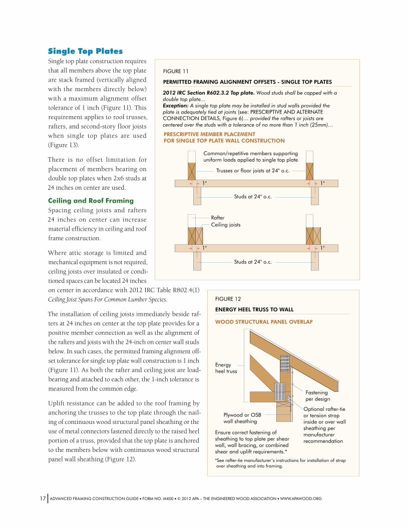
Single Top PlatesSingle top plate construction requires
that all members above the top plate
are stack framed (vertically aligned
with the members directly below)
with a maximum alignment offset
tolerance of 1 inch (Figure 11). This
requirement applies to roof trusses,
rafters, and second-story floor joists
when single top plates are used
(Figure 13).
There is no offset limitation for
placement of members bearing on
double top plates when 2x6 studs at
24 inches on center are used.
Ceiling and Roof FramingSpacing ceiling joists and rafters
24 inches on center can increase
material efficiency in ceiling and roof
frame construction.
Where attic storage is limited and
mechanical equipment is not required,
ceiling joists over insulated or condi-
tioned spaces can be located 24 inches
on center in accordance with 2012 IRC Table R802.4(1)
Ceiling Joist Spans For Common Lumber Species.
The installation of ceiling joists immediately beside raf-
ters at 24 inches on center at the top plate provides for a
positive member connection as well as the alignment of
the rafters and joists with the 24-inch on center wall studs
below. In such cases, the permitted framing alignment off-
set tolerance for single top plate wall construction is 1 inch
(Figure 11). As both the rafter and ceiling joist are load-
bearing and attached to each other, the 1-inch tolerance is
measured from the common edge.
Uplift resistance can be added to the roof framing by
anchoring the trusses to the top plate through the nail-
ing of continuous wood structural panel sheathing or the
use of metal connectors fastened directly to the raised heel
portion of a truss, provided that the top plate is anchored
to the members below with continuous wood structural
panel wall sheathing (Figure 12).
FIGURE 11
PERMITTED FRAMING ALIGNMENT OFFSETS - SINGLE TOP PLATES
PRESCRIPTIVE MEMBER PLACEMENTFOR SINGLE TOP PLATE WALL CONSTRUCTION
Trusses or floor joists at 24" o.c.
Studs at 24" o.c.
1" 1"
2012 IRC Section R602.3.2 Top plate. Wood studs shall be capped with a double top plate...Exception: A single top plate may be installed in stud walls provided the plate is adequately tied at joints (see: PRESCRIPTIVE AND ALTERNATE CONNECTION DETAILS, Figure 6)… provided the rafters or joists are centered over the studs with a tolerance of no more than 1 inch (25mm)…
RafterCeiling joists
Studs at 24" o.c.
1" 1"
Common/repetitive members supporting uniform loads applied to single top plate
Optional rafter-tie or tension strap inside or over wall sheathing per manufacturer recommendation
Fasteningper design
Plywood or OSBwall sheathing
FIGURE 12
ENERGY HEEL TRUSS TO WALL
Ensure correct fastening of sheathing to top plate per shear wall, wall bracing, or combined shear and uplift requirements.*
WOOD STRUCTURAL PANEL OVERLAP
*See rafter-tie manufacturer’s instructions for installation of strap over sheathing and into framing.
Energyheel truss
ADVANCEDFRAMINGCONSTRUCTIONGUIDE■FORMNO.M400■©2012APA–THEENGINEEREDWOODASSOCIATION■WWW.APAWOOD.ORG17
The 2012 IECC (International Energy Conservation Code) Section 402.2.1 Ceilings with attic spaces allows a reduction
in the prescriptive attic insulation requirements provided that the uncompressed depth of attic insulation extends
over the wall top plate. When energy heel (or raised heel) trusses are used to satisfy this requirement, uncompressed
R30 insulation is deemed to satisfy R38 requirements and uncompressed R38 insulation is deemed to satisfy R49 attic
insulation requirements. Energy heel roof construction requires an insulation depth of 10 inches for most R30 batt,
loose-fill fiberglass or cellulose insulation, and a depth of roughly 12 inches for R38 insulation.
Single Top Plates and Framing Member LayoutSingle top plate construction requires vertical framing alignment, in which framing members are “stacked” to create
a direct load path. This approach requires a single – or master – framing layout for all members at all framing levels,
as illustrated in Figure 13.
When designing a master framing layout, start with the layout of the roof framing members, which is generally dictated
by roof design and geometry, followed by the layout of the framing members below. Although this will be a change
in approach for framing carpenters who are accustomed to working up from the foundation, addressing the roof first
will simplify load calculation for the designer and maximize material efficiency.
The type of roof design will impact the master framing layout. For example, hip roof design will usually require a dif-
ferent starting point for framing member layout than gable roof design. In hip roof construction, common rafters and
hip jack rafters typically layout from the nominal center line intersection of the hip(s) with the ridge. In gable roof con-
struction, common rafter layout typically commences from one of the end walls of the structure.
Framing member layout will also be dictated by the type of roof construction. Truss roofs will often require a differ-
ent framing member layout than framed roofs.
When trusses are specified, the trusses should be stacked directly above the wall studs. There is no member offset,
hence the truss and wall stud layout will be the same.
Wall SheathingThe potential for panel buckling between studs increases when stud spacing is widened from 16 to 24 inches on center,
especially when the sheathing is subjected to moisture exposure during construction. Although this is not a structural
concern, excessive buckling may cause serviceability issues. Therefore, it is imperative that builders pay close atten-
tion to the moisture management of wood structural panels on the jobsite in addition to APA recommendations for
spacing panels 1/8 inch at panel ends and edges. Additional information on preventing wall sheathing from buckling
is provided in APA Technical Note: Minimize Buckling of Wood Structural Panels, Form X480.
Wind Resistance and Wall AssembliesSevere storms, tornadoes and destructive winds produce multiple forces that threaten buildings:
■■ Lateral forces that push against the building, causing walls to rack out of square and weaken the structure. Seismic events also exert lateral forces on buildings.
■■ Uplift forces that work against gravity to separate the roof from the walls, the walls from the floor, and the floor from the foundation.
■■ Inward and outward wind pressures that pull on the cladding and sheathing and can separate sections of the roof and walls from the building, potentially exposing the interior to moisture and air infiltration.
All structures built to the specifications of the 2012 IRC are required to resist these loads, in accordance with Section
R301.2.1 Wind design criteria. Any effort to meet energy code requirements or increase the energy efficiency of a build-
ing must be balanced with structural performance and the structural requirements of the code.
ADVANCEDFRAMINGCONSTRUCTIONGUIDE■FORMNO.M400■©2012APA–THEENGINEEREDWOODASSOCIATION■WWW.APAWOOD.ORG18

APA plywood or OSB roof sheathing(omitted for clarity)
Roof trusses (energy heelroof trusses shown) 24" o.c.
Single top plate
Framing members “stack”to create direct load path
APA plywood or OSB wall sheathing
2x6 studs 24" o.c. supportingone floor, roof and ceiling.Height limitations percode requirements.
APA Sturd-I-Floor®
minimum 24 oc
APA Rim Board®
APA wood I-joists or SCL 24" o.c.
FIGURE 13
STACK FRAMING AND 24" O.C. MEMBER SPACING
Framing members are stack framed and vertically aligned to create direct load path.
The 2012 IRC specifies regions that are subject to higher wind loads and thus require greater uplift and shear resis-
tance. Buildings in these regions are beyond the scope of the prescriptive code requirements of the IRC and should
be designed in accordance with the International Building Code (IBC) or other engineering standards.
While wind loads vary by location, no region is completely immune to the forces of nature. The wall assembly is
integral to the structure’s resistance to wind loads. When properly designed and constructed, advanced framing in
conjunction with continuous wood structural panel wall sheathing provides walls with the strength to safely with-
stand these forces. Refer to Table 1 for the requirements for wood structural panel wall sheathing used to resist wind
pressures, including options for 24-inch on center stud spacing.
ADVANCEDFRAMINGCONSTRUCTIONGUIDE■FORMNO.M400■©2012APA–THEENGINEEREDWOODASSOCIATION■WWW.APAWOOD.ORG19
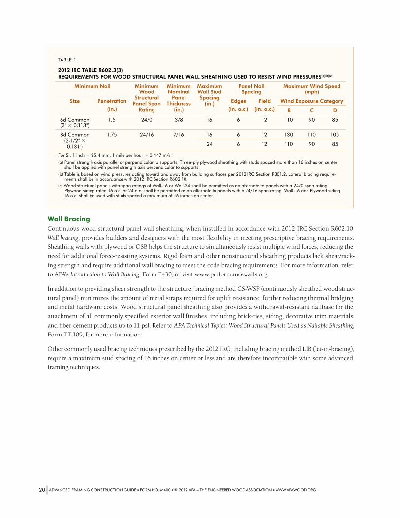
TABLE1
2012 irC TABlE r602 .3(3) rEqUirEMENTs for Wood sTrUCTUrAl PANEl WAll shEAThiNg UsEd To rEsisT WiNd PrEssUrEs(a)(b)(c)
Minimum Nail Minimum Wood
structural Panel span
rating
Minimum Nominal
Panel Thickness
(in .)
Maximum Wall stud spacing
(in .)
Panel Nail spacing
Maximum Wind speed (mph)
size Penetration
(in .)
Edges
(in . o .c .)
field
(in . o .c .)
Wind Exposure Category
B C d
6dCommon(2"×0.113")
1.5 24/0 3/8 16 6 12 110 90 85
8dCommon(2-1/2"×0.131")
1.75 24/16 7/16 16 6 12 130 110 105
24 6 12 110 90 85
ForSI:1inch=25.4mm,1mileperhour=0.447m/s.
(a)Panelstrengthaxisparallelorperpendiculartosupports.Three-plyplywoodsheathingwithstudsspacedmorethan16inchesoncentershallbeappliedwithpanelstrengthaxisperpendiculartosupports.
(b)Tableisbasedonwindpressuresactingtowardandawayfrombuildingsurfacesper2012IRCSectionR301.2.Lateralbracingrequire-mentsshallbeinaccordancewith2012IRCSectionR602.10.
(c)WoodstructuralpanelswithspanratingsofWall-16orWall-24shallbepermittedasanalternatetopanelswitha24/0spanrating.Plywoodsidingrated16o.c.or24o.c.shallbepermittedasanalternatetopanelswitha24/16spanrating.Wall-16andPlywoodsiding16o.c.shallbeusedwithstudsspacedamaximumof16inchesoncenter.
Wall BracingContinuous wood structural panel wall sheathing, when installed in accordance with 2012 IRC Section R602.10
Wall bracing, provides builders and designers with the most flexibility in meeting prescriptive bracing requirements.
Sheathing walls with plywood or OSB helps the structure to simultaneously resist multiple wind forces, reducing the
need for additional force-resisting systems. Rigid foam and other nonstructural sheathing products lack shear/rack-
ing strength and require additional wall bracing to meet the code bracing requirements. For more information, refer
to APA’s Introduction to Wall Bracing, Form F430, or visit www.performancewalls.org.
In addition to providing shear strength to the structure, bracing method CS-WSP (continuously sheathed wood struc-
tural panel) minimizes the amount of metal straps required for uplift resistance, further reducing thermal bridging
and metal hardware costs. Wood structural panel sheathing also provides a withdrawal-resistant nailbase for the
attachment of all commonly specified exterior wall finishes, including brick-ties, siding, decorative trim materials
and fiber-cement products up to 11 psf. Refer to APA Technical Topics: Wood Structural Panels Used as Nailable Sheathing,
Form TT-109, for more information.
Other commonly used bracing techniques prescribed by the 2012 IRC, including bracing method LIB (let-in-bracing),
require a maximum stud spacing of 16 inches on center or less and are therefore incompatible with some advanced
framing techniques.
ADVANCEDFRAMINGCONSTRUCTIONGUIDE■FORMNO.M400■©2012APA–THEENGINEEREDWOODASSOCIATION■WWW.APAWOOD.ORG20
More InformationEngineered Wood Construction SystemsAPA offers a comprehensive set of services and tools for architects, engineers and building designers. If you’re looking
for detailed product information, training materials or technical assistance, APA can help.
www.apawood.org – APA’s website is your link to in-depth design and building support, including a library of more
than 400 publications available for instant PDF download or hard-copy purchase.
APA Product Support Help Desk – Staffed by specialists who have the knowledge to address a diverse range of inqui-
ries, the Help Desk can answer your questions about specification and application of APA products, or put you in touch
with your nearest engineered wood specialist. Call (253) 620-7400 or send an email to [email protected].
Wall Bracing – Understanding the code requirements for wall bracing can be a challenge, but following them is of crit-
ical importance to the structural integrity of a home. APA helps you easily understand, design and build wall bracing
systems. The following publications and more information are available at www.performancewalls.org.
■■ Introduction to Wall Bracing, Form F430
■■ Brace Walls with Wood, Form G440
For additional wall bracing information, refer to A Guide to the 2009 IRC® Wood Wall Bracing Provisions, authored by
APA and the International Code Council® (ICC®). The guide and wall bracing seminars and resources are available at
www.iccsafe.org.
Build a Better Home – APA’s Build a Better Home program is designed to provide builders and homeowners with the
construction guidelines they need to protect their homes against damaging moisture infiltration. Key elements in the
building envelope are the roof, walls and foundation. The following publications and more information are available
at www.buildabetterhome.org.
■■ Build A Better Home: Foundations, Form A520
■■ Build A Better Home: Mold and Mildew, Form A525
■■ Build A Better Home: Roofs, Form A535
■■ Build A Better Home: Walls, Form A530
ADVANCEDFRAMINGCONSTRUCTIONGUIDE■FORMNO.M400■©2012APA–THEENGINEEREDWOODASSOCIATION■WWW.APAWOOD.ORG21
Building Codes Referenced in this Guide■■ 2012 International Building Code (published by the International Code Council)
■■ 2012 International Energy Conservation Code (published by the International Code Council)
■■ 2012 International Residential Code (published by the International Code Council)
Additional References■■ 2012 Wood Frame Construction Manual (published by the American Wood Council): www.awc.org/standards/wfcm.html
■■ ENERGY STAR®: www.energystar.gov
■■ National Association of Home Builders, ICC 700 National Green Building Standard: www.nahbgreen.org/NGBS
■■ National Association of Home Builders, NAHB Research Center: www.nahbrc.com
■■ National Institute of Building Sciences: www.nibs.org
■■ U.S. Department of Energy, Building Energy Codes Program: www.energycodes.gov
■■ U.S. Department of Energy, Building Technologies Program: www.eere.energy.gov/buildings
■■ U.S. Department of Energy, Office of Energy Efficiency and Renewable Energy: www.eere.energy.gov
■■ U.S. Green Building Council, LEED® Rating System: www.usgbc.org/leed
Acknowledgements■■ Tony Mainsbridge, advanced framing consultant, contributed to the recommendations in this guide.
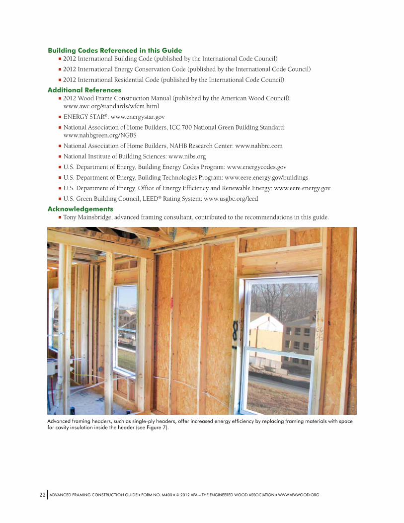
Advancedframingheaders,suchassingle-plyheaders,offerincreasedenergyefficiencybyreplacingframingmaterialswithspaceforcavityinsulationinsidetheheader(seeFigure7).
ADVANCEDFRAMINGCONSTRUCTIONGUIDE■FORMNO.M400■©2012APA–THEENGINEEREDWOODASSOCIATION■WWW.APAWOOD.ORG22
About APAAPA is a nonprofit trade association of and for wood
structural panel, glulam timber, wood I-joist, struc-
tural composite lumber, and other engineered
wood product manufacturers. Based in Tacoma,
Washington, APA represents approximately 150 mills
throughout North America, ranging from small, inde-
pendently owned and operated companies to large
integrated corporations.
APA is a leader in wood-design testing and research.
APA’s 42,000-square-foot Research Center is staffed
with an experienced corps of engineers, wood scien-
tists, and wood-product technicians. Their expertise
plays an important role in producing panel and engi-
neered wood systems that meet the industry’s highest
performance standards and braced-wall designs that promote the structural safety of building construction.
For our latest information in building strong, safe and durable structures, visit www.apawood.org.
ADVANCEDFRAMINGCONSTRUCTIONGUIDE■FORMNO.M400■©2012APA–THEENGINEEREDWOODASSOCIATION■WWW.APAWOOD.ORG23
Advanced Framing Construction GuideWehavefieldrepresentativesinmanymajorU.S.citiesandinCanada
whocanhelpanswerquestionsinvolvingAPAtrademarkedproducts.Foradditionalassistanceinspecifyingengineeredwoodproducts,contactus:
APA hEAdqUArTErs7011So.19thSt.■Tacoma,Washington98466
(253)565-6600■Fax:(253)565-7265
ProdUCT sUPPorT hElP dEsk(253)620-7400
E-mailAddress:[email protected]
disClAiMErThe information contained herein is based on APA – The Engineered Wood Association’s continuing programs of laboratory testing, product research, and comprehensive field experi-ence . Neither APA, nor its members make any warranty, expressed or implied, or assume any legal liability or responsibility for the use, application of, and/or reference to opinions, findings, conclusions, or recommendations included in this publication . Consult your local jurisdiction or design professional to assure compliance with code, construction, and performance require-ments . Because APA has no control over quality of workmanship or the conditions under which engineered wood products are used, it cannot accept responsibility of product performance or designs as actually constructed .
FormNo.M400/IssuedFebruary2012/0200