

Advanced Fatigue from nCode - Ansys UK/staticassets...Advanced Fatigue from nCode 1 ... •...
31
Advanced Fatigue from nCode 1 Robert Cawte Principal Applications Engineer HBM-nCode
Transcript of Advanced Fatigue from nCode - Ansys UK/staticassets...Advanced Fatigue from nCode 1 ... •...

Advanced Fatigue from nCode
1
Robert Cawte
Principal Applications Engineer
HBM-nCode
Contents
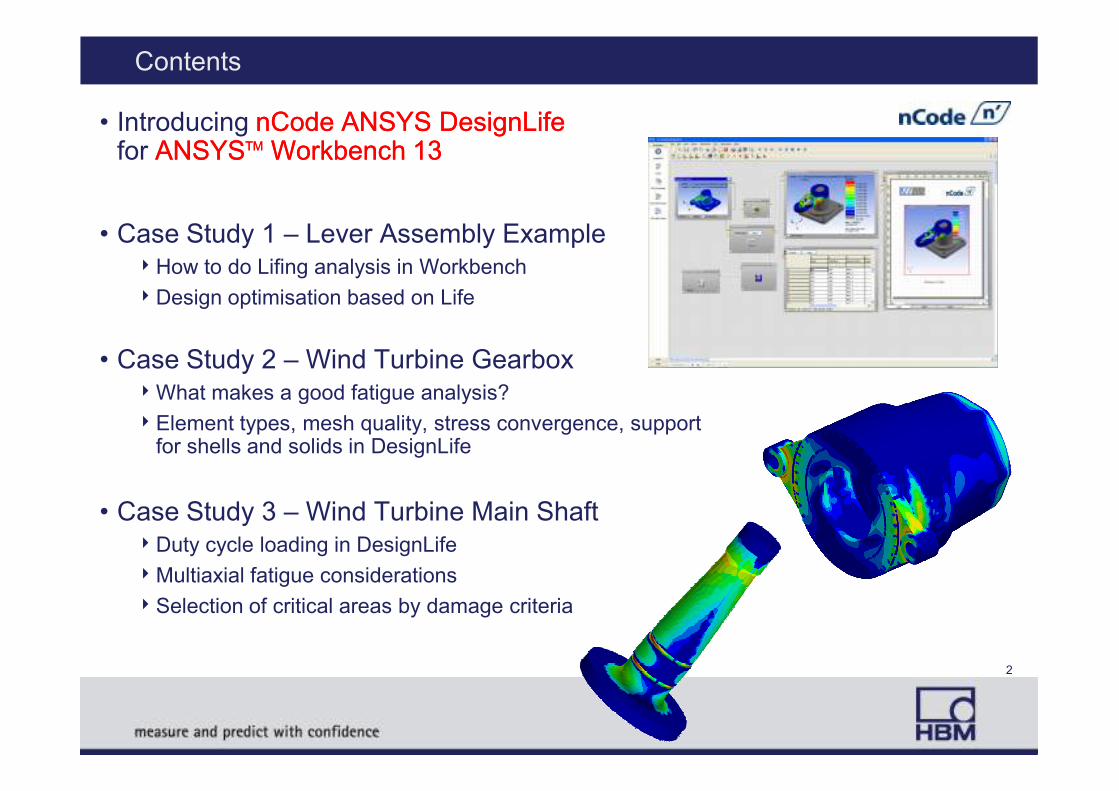
• Introducing nCode ANSYS DesignLife nCode ANSYS DesignLife for ANSYSANSYSTMTM Workbench 13Workbench 13
• Case Study 1 – Lever Assembly Example4How to do Lifing analysis in Workbench
4Design optimisation based on Life
• Case Study 2 – Wind Turbine Gearbox4What makes a good fatigue analysis?4What makes a good fatigue analysis?
4Element types, mesh quality, stress convergence, support for shells and solids in DesignLife
• Case Study 3 – Wind Turbine Main Shaft4Duty cycle loading in DesignLife
4Multiaxial fatigue considerations
4Selection of critical areas by damage criteria
2
What is nCode DesignLife ?
•A fatigue analysis solver & interface for FE users
4Part of nCode GlyphWorks (signal processing)
• To encourage test-FE collaboration
4Customised for Ansys users (DesignLife only)
•DesignLife is both flexible and rigid !
4Flexibility to set up the required analysis options4Flexibility to set up the required analysis options
4Rigid – options are saved in a locked process flow
•Re-used to give consistent process results
•DesignLife works from Ansys RST files
4and/or sits inside Workbench
3
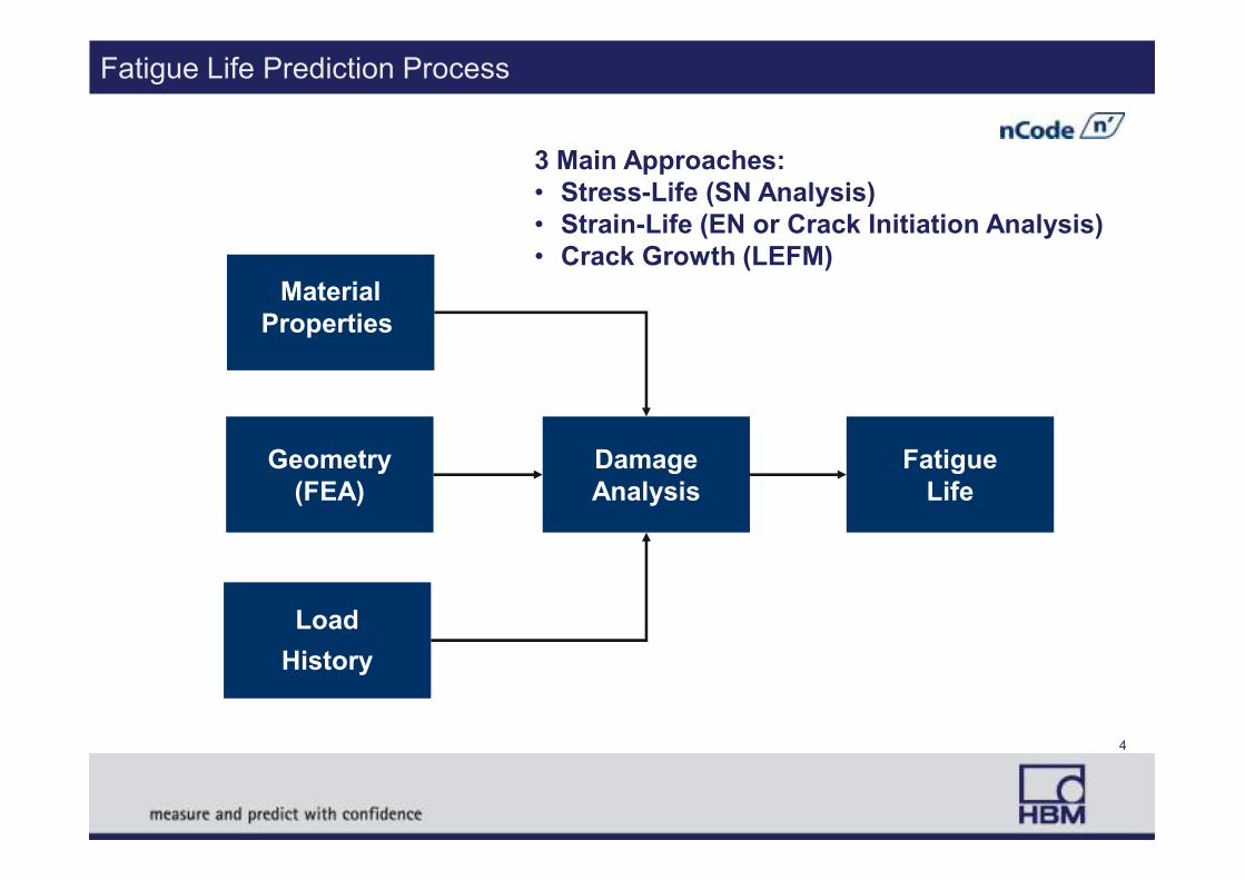
Fatigue Life Prediction Process
Material
Properties
3 Main Approaches:
• Stress-Life (SN Analysis)
• Strain-Life (EN or Crack Initiation Analysis)
• Crack Growth (LEFM)
Load
History
Geometry
(FEA)
Damage
Analysis
Fatigue
Life
4
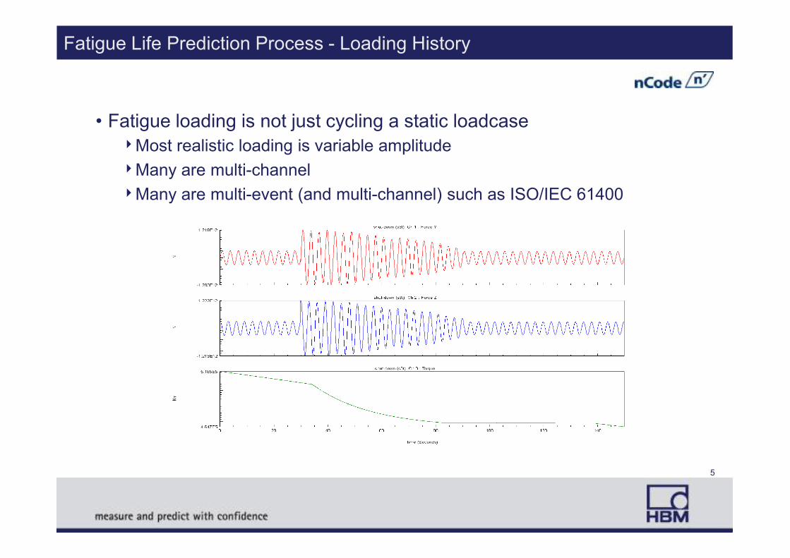
Fatigue Life Prediction Process - Loading History
• Fatigue loading is not just cycling a static loadcase
4Most realistic loading is variable amplitude
4Many are multi-channel
4Many are multi-event (and multi-channel) such as ISO/IEC 61400
5
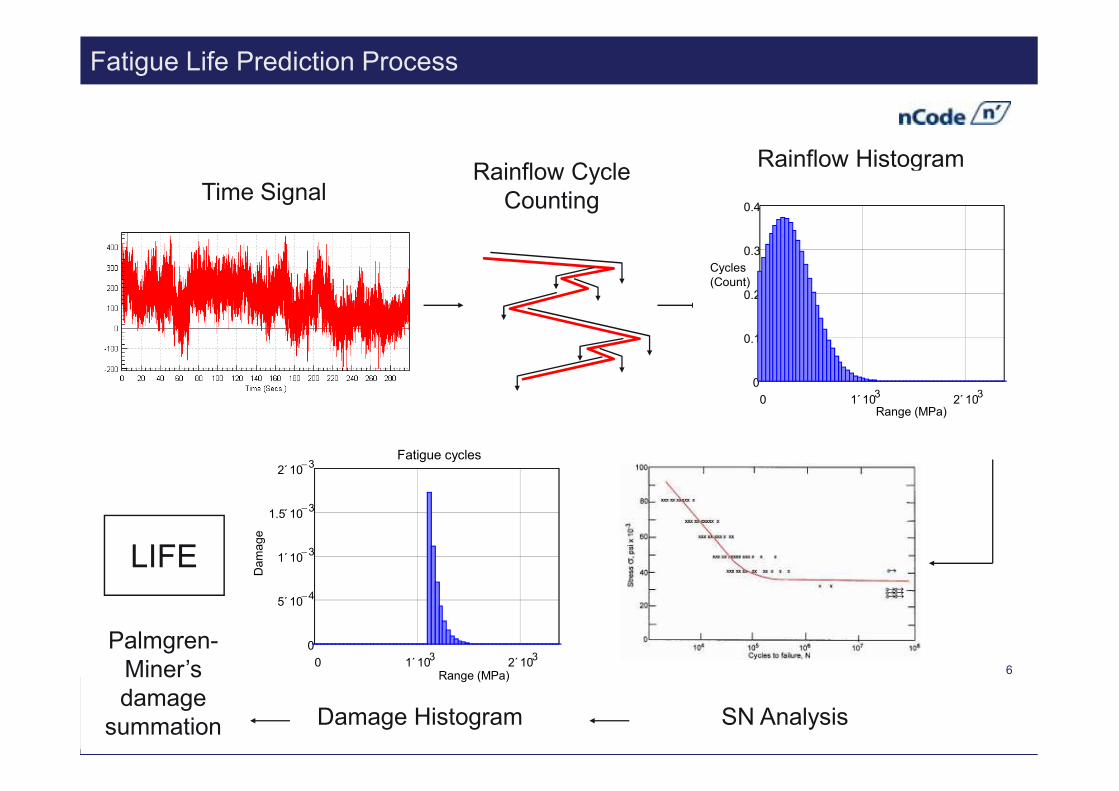
Rainflow Cycle
Counting
Fatigue Life Prediction Process
Time Signal
Rainflow Histogram
0 1 103
´ 2 103
´
0
0.1
0.2
0.3
0.4
Cycles
(Count)
LIFE
SN AnalysisDamage Histogram
Palmgren-
Miner’s
damage
summation
0 1 103
´ 2 103
´
0
5 104−
´
1 103−
´
1.5 103−
´
2 103−
´
Fatigue cycles
Range (MPa)
Damage
0 1 103
´ 2 103
´Range (MPa)
6
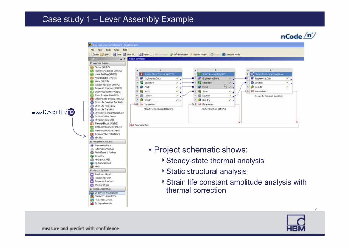
Case study 1 – Lever Assembly Example
• Project schematic shows:
4Steady-state thermal analysis
4Static structural analysis
4Strain life constant amplitude analysis with thermal correction
7
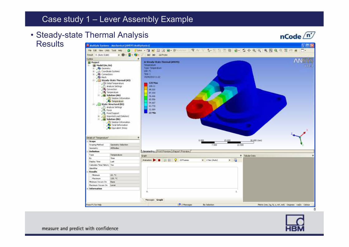
Case study 1 – Lever Assembly Example
• Steady-state Thermal Analysis Results
8
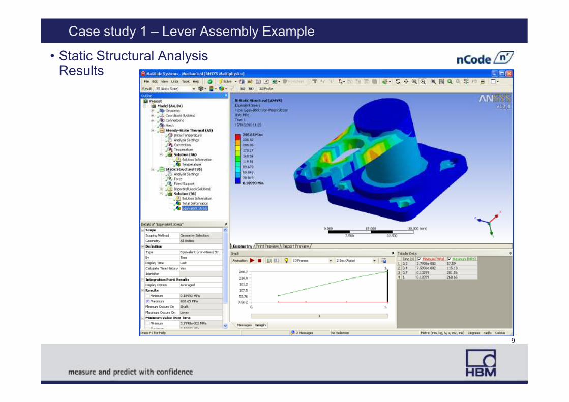
Case study 1 – Lever Assembly Example
• Static Structural Analysis Results
9
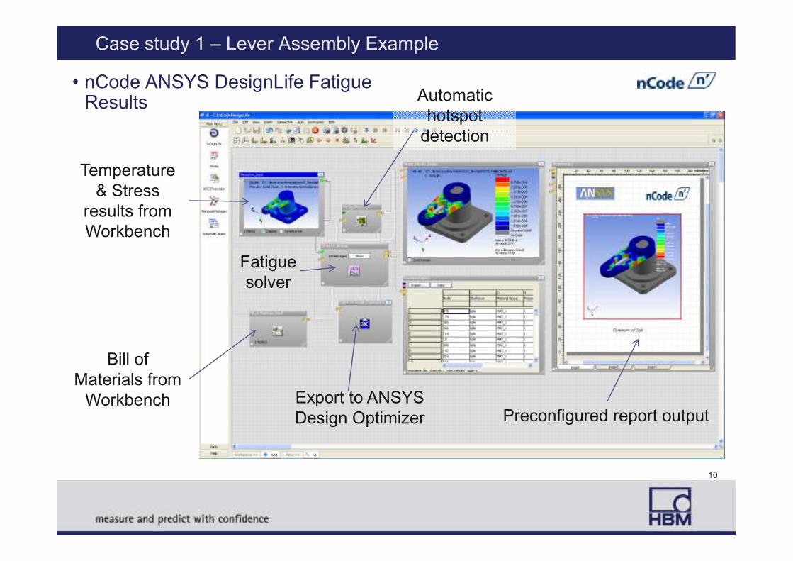
Case study 1 – Lever Assembly Example
• nCode ANSYS DesignLife Fatigue Results
Temperature
& Stress
results from
Workbench
Automatic
hotspot
detection
Fatigue
solver
10
Bill of
Materials from
WorkbenchPreconfigured report output
solver
Export to ANSYS
Design Optimizer
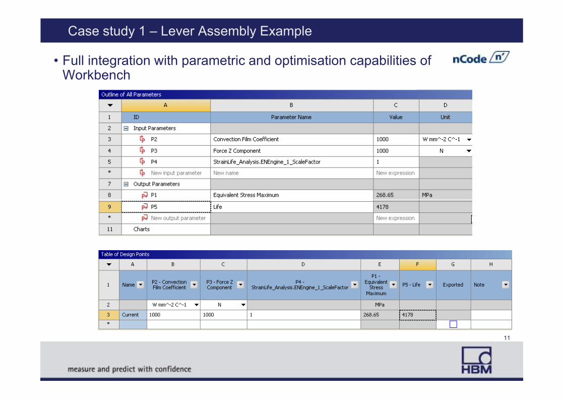
Case study 1 – Lever Assembly Example
• Full integration with parametric and optimisation capabilities of Workbench
11

Case Study 2 – Wind Turbine Gearbox
Ref 1. Improving Wind Turbine Gearbox Reliability
W. Musial and S. Butterfield National Renewable Energy Laboratory, B. McNiff McNiff Light Industry
Presented at the 2007 European Wind Energy Conference Milan, Italy , May 7–10, 2007
Generalized Gearbox Schematic1
12
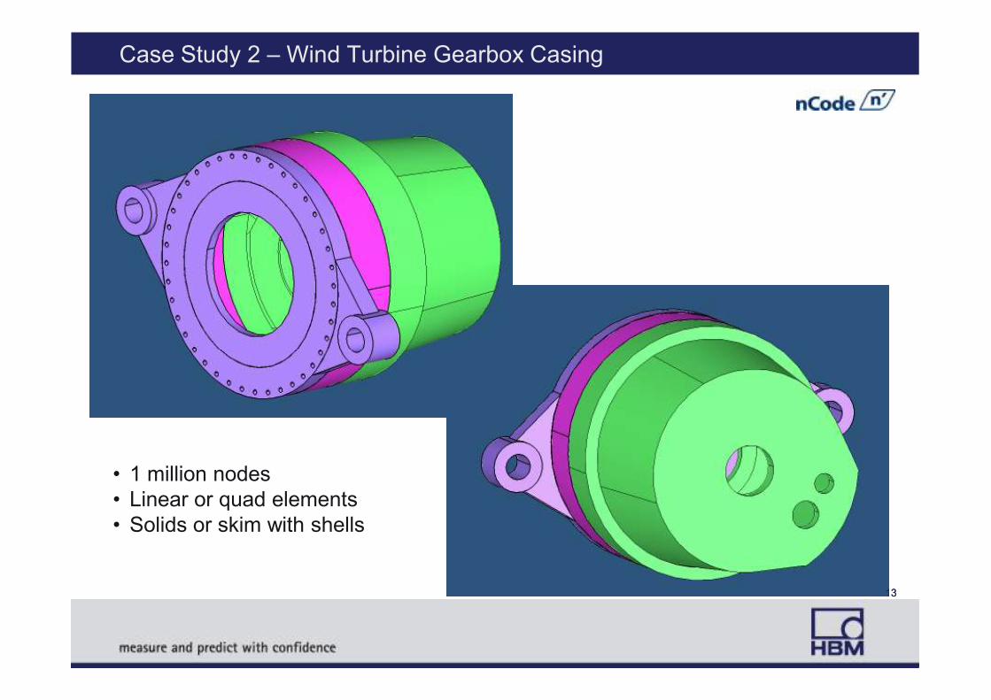
Case Study 2 – Wind Turbine Gearbox Casing
13
• 1 million nodes
• Linear or quad elements
• Solids or skim with shells
13
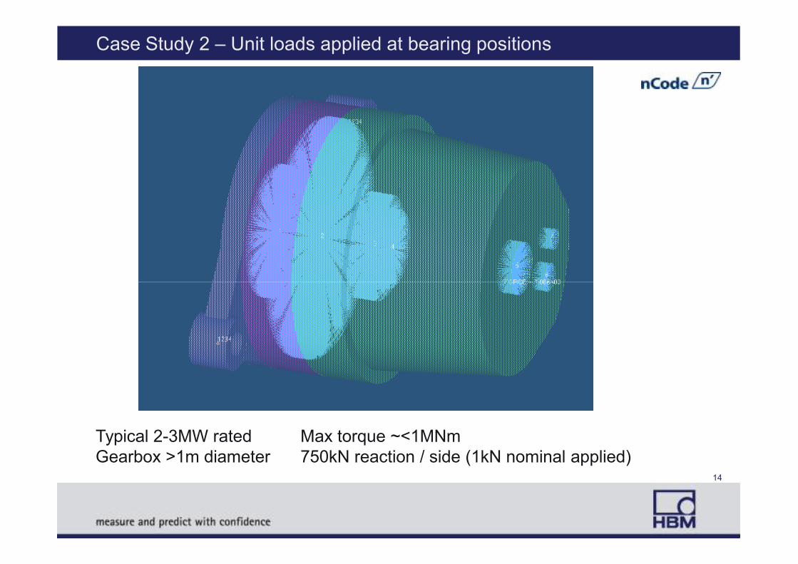
Case Study 2 – Unit loads applied at bearing positions
Typical 2-3MW rated Max torque ~<1MNm
Gearbox >1m diameter 750kN reaction / side (1kN nominal applied)14
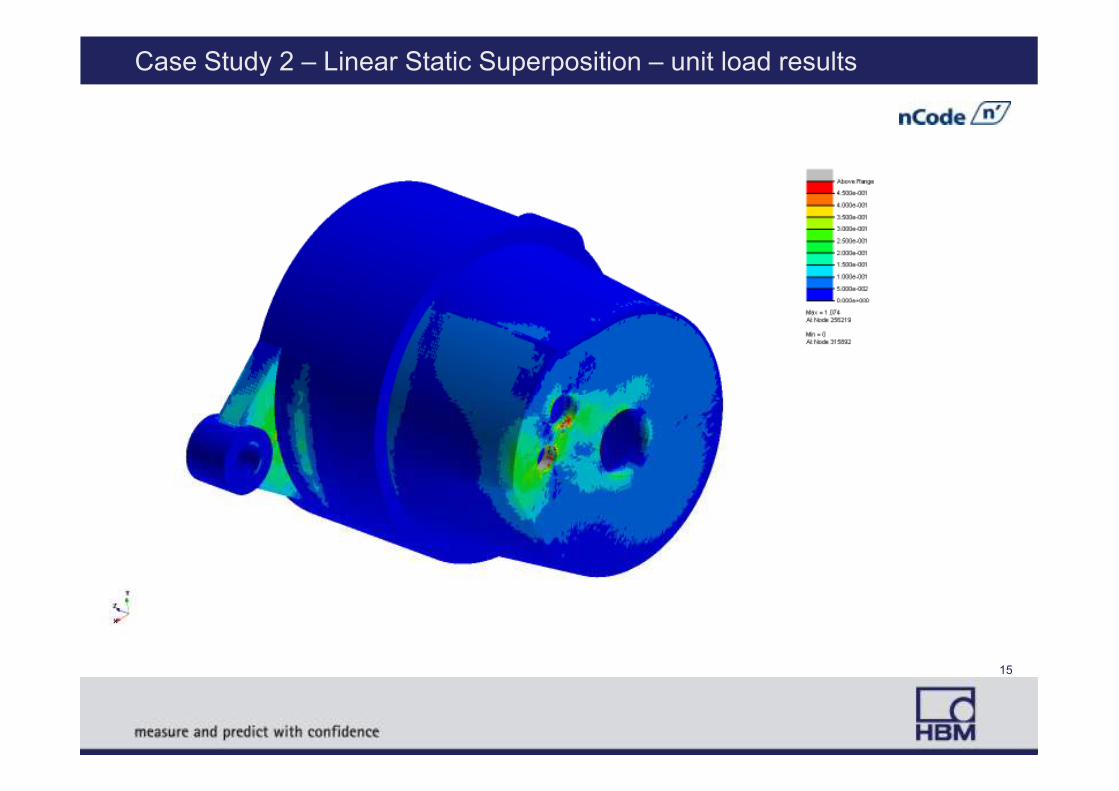
Case Study 2 – Linear Static Superposition – unit load results
15
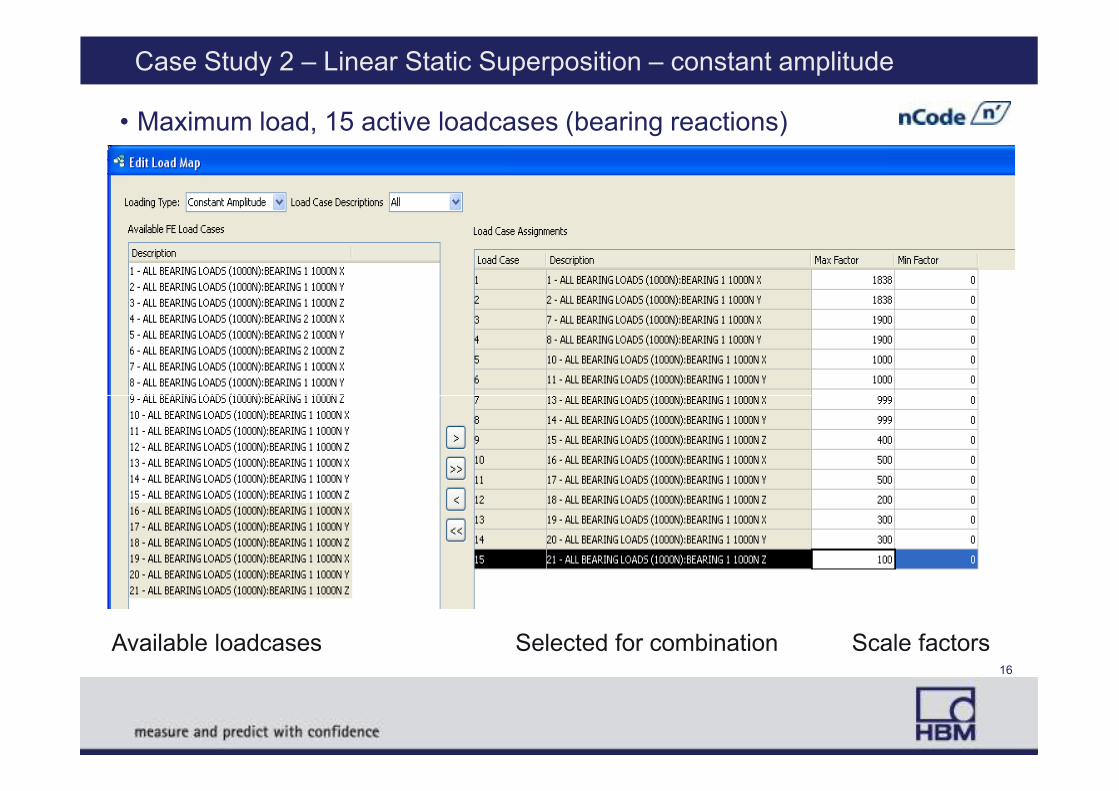
Case Study 2 – Linear Static Superposition – constant amplitude
• Maximum load, 15 active loadcases (bearing reactions)
Available loadcases Selected for combination Scale factors16

Case Study 2 – Fatigue results
Stress resultsLife results
Linear elementsLife results
Quad elements
17
SN Fatigue Test Analysis
Stress Range S
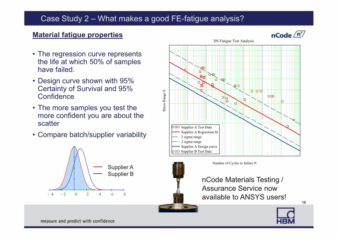
Material fatigue properties
• The regression curve represents the life at which 50% of samples have failed.
• Design curve shown with 95% Certainty of Survival and 95% Confidence
• The more samples you test the more confident you are about the scatter
Case Study 2 – What makes a good FE-fatigue analysis?
Supplier A Test Data
Supplier A Regression fit
2 sigma range
2 sigma range
Supplier A Design curve
Supplier B Test Data
Number of Cycles to failure N
scatter
• Compare batch/supplier variability
4− 2− 0 2 4 6 8
18
Supplier A
Supplier BnCode Materials Testing /
Assurance Service now
available to ANSYS users!18
Case Study 2 – What makes a good FE-fatigue analysis?
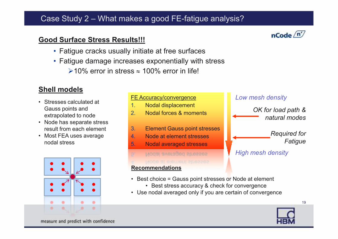
Good Surface Stress Results!!!
FE Accuracy/convergence
1. Nodal displacement
2. Nodal forces & moments
FE Accuracy/convergence
1. Nodal displacement
2. Nodal forces & moments
Low mesh density
OK for load path &
natural modes
• Fatigue cracks usually initiate at free surfaces
• Fatigue damage increases exponentially with stress
�10% error in stress ≈ 100% error in life!
Shell models
• Stresses calculated at
Gauss points and
extrapolated to node
• Node has separate stress 3. Element Gauss point stresses
4. Node at element stresses
5. Nodal averaged stresses
3. Element Gauss point stresses
4. Node at element stresses
5. Nodal averaged stresses
High mesh density
natural modes
Required for
Fatigue
• Node has separate stress
result from each element
• Most FEA uses average
nodal stress
Recommendations
• Best choice = Gauss point stresses or Node at element
• Best stress accuracy & check for convergence
• Use nodal averaged only if you are certain of convergence
19
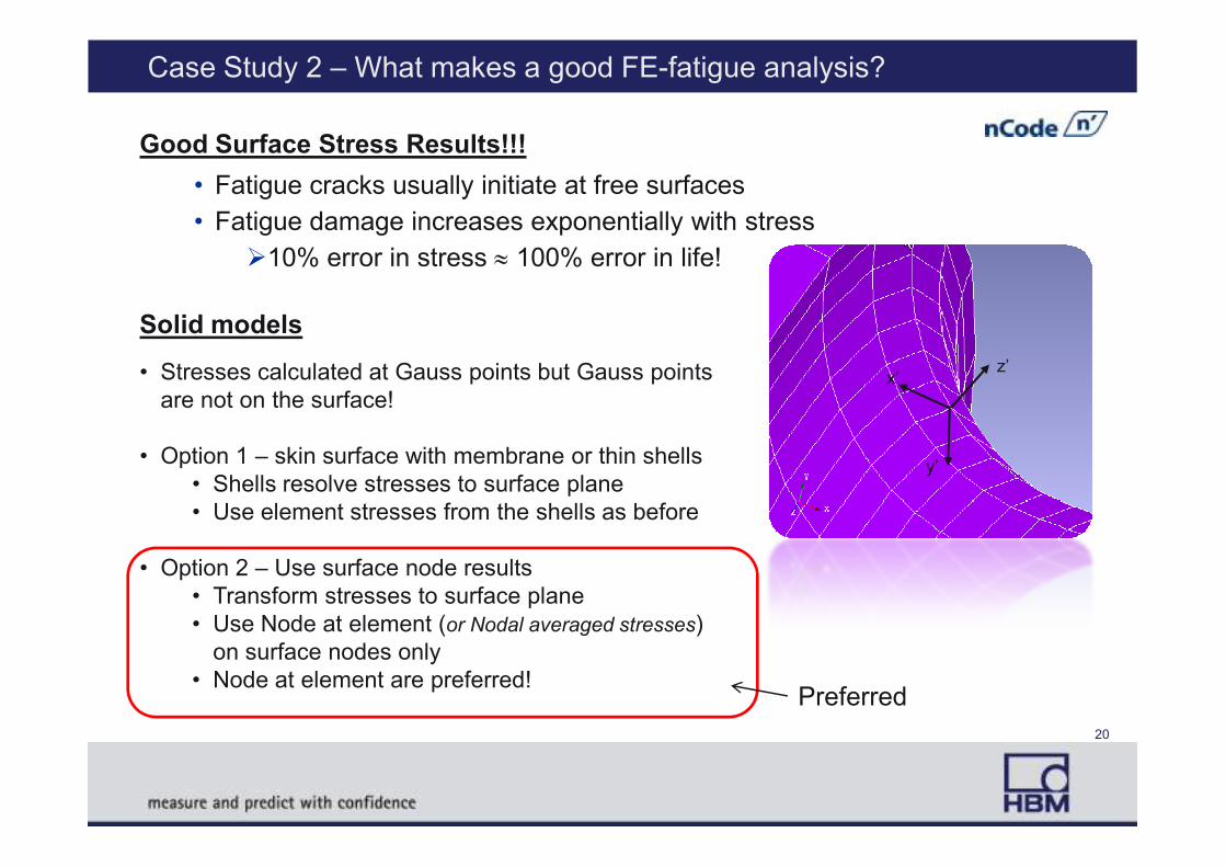
Case Study 2 – What makes a good FE-fatigue analysis?
Good Surface Stress Results!!!
• Fatigue cracks usually initiate at free surfaces
• Fatigue damage increases exponentially with stress
�10% error in stress ≈ 100% error in life!
Solid models
• Stresses calculated at Gauss points but Gauss points
are not on the surface!x’
z’
• Option 1 – skin surface with membrane or thin shells
• Shells resolve stresses to surface plane
• Use element stresses from the shells as before
• Option 2 – Use surface node results
• Transform stresses to surface plane
• Use Node at element (or Nodal averaged stresses)
on surface nodes only
• Node at element are preferred!
y’
Preferred
20
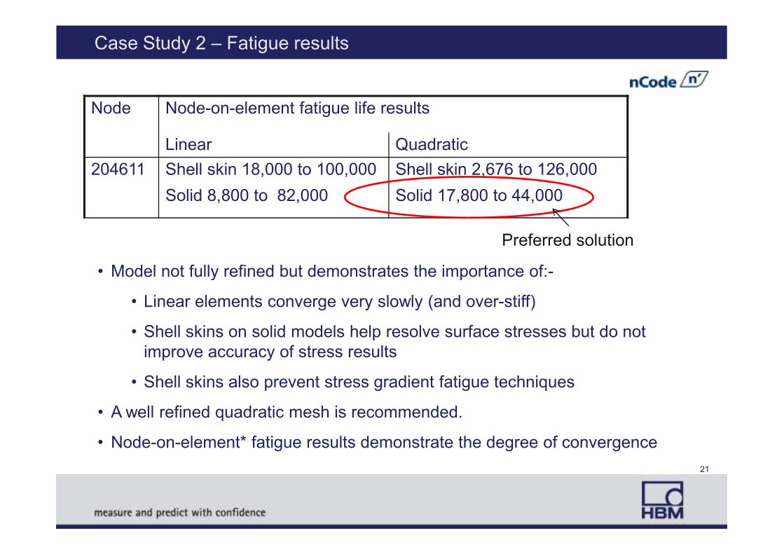
Case Study 2 – Fatigue results
Node Node-on-element fatigue life results
Linear Quadratic
204611 Shell skin 18,000 to 100,000
Solid 8,800 to 82,000
Shell skin 2,676 to 126,000
Solid 17,800 to 44,000
• Model not fully refined but demonstrates the importance of:-
Preferred solution
• Model not fully refined but demonstrates the importance of:-
• Linear elements converge very slowly (and over-stiff)
• Shell skins on solid models help resolve surface stresses but do not
improve accuracy of stress results
• Shell skins also prevent stress gradient fatigue techniques
• A well refined quadratic mesh is recommended.
• Node-on-element* fatigue results demonstrate the degree of convergence
21
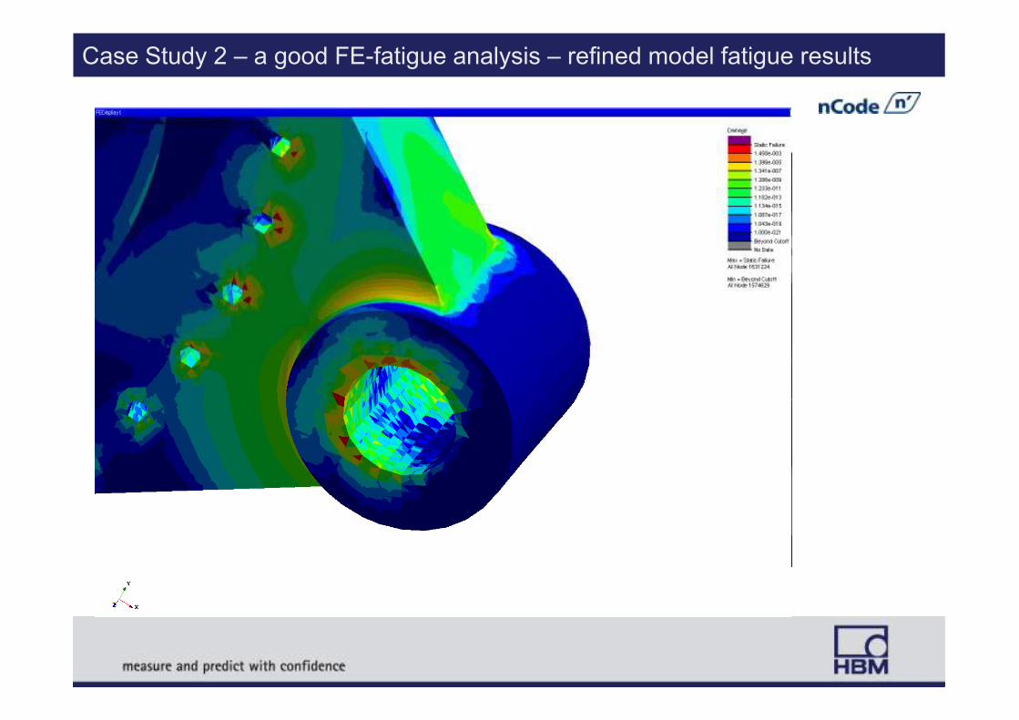
Case Study 2 – a good FE-fatigue analysis – refined model fatigue results

Case study 3 – Analysis of main drive shaft
23
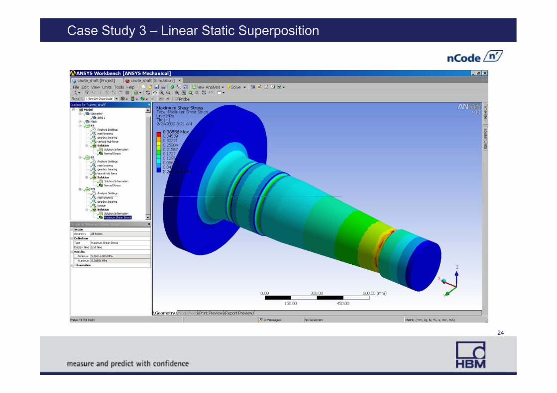
Case Study 3 – Linear Static Superposition
24
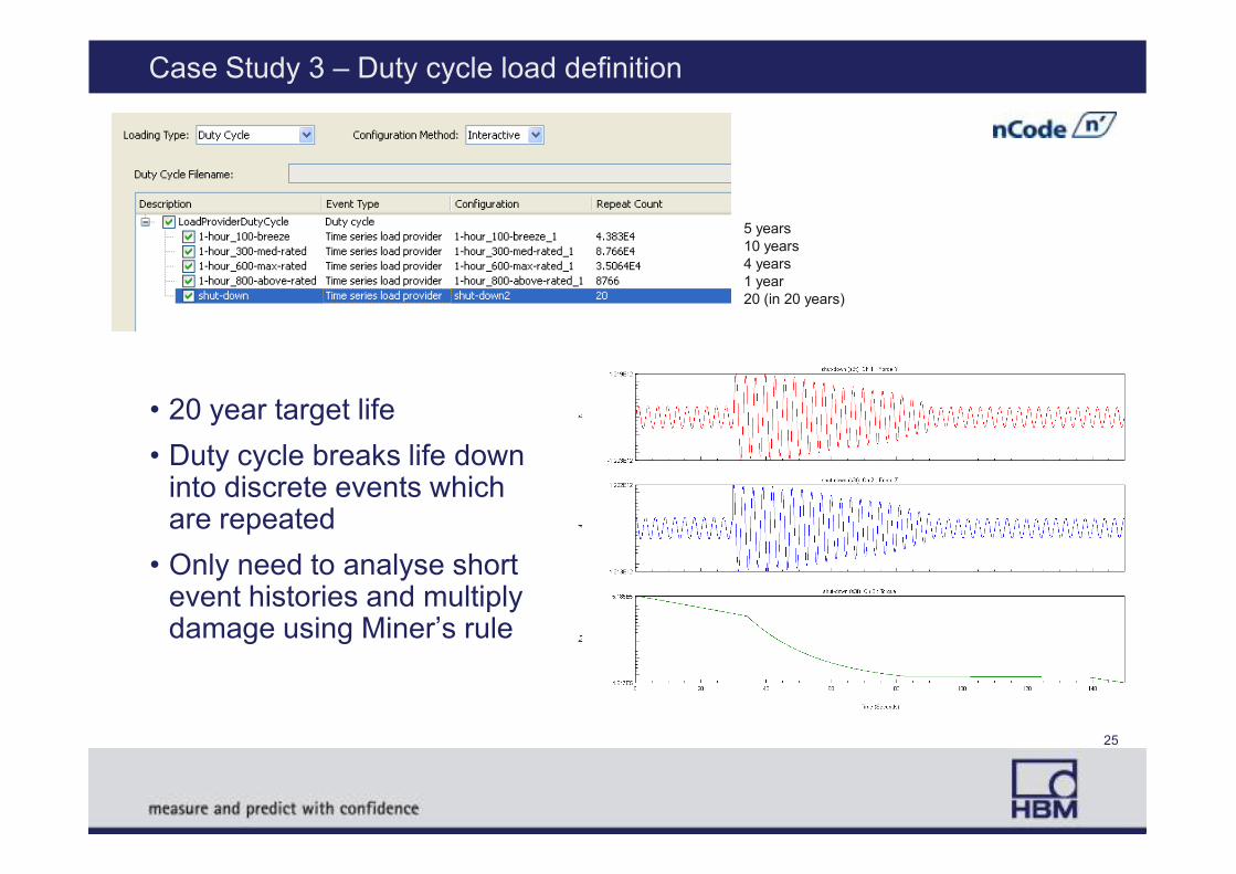
Case Study 3 – Duty cycle load definition
• 20 year target life
5 years
10 years
4 years
1 year
20 (in 20 years)
• Duty cycle breaks life down into discrete events which are repeated
• Only need to analyse short event histories and multiply damage using Miner’s rule
25
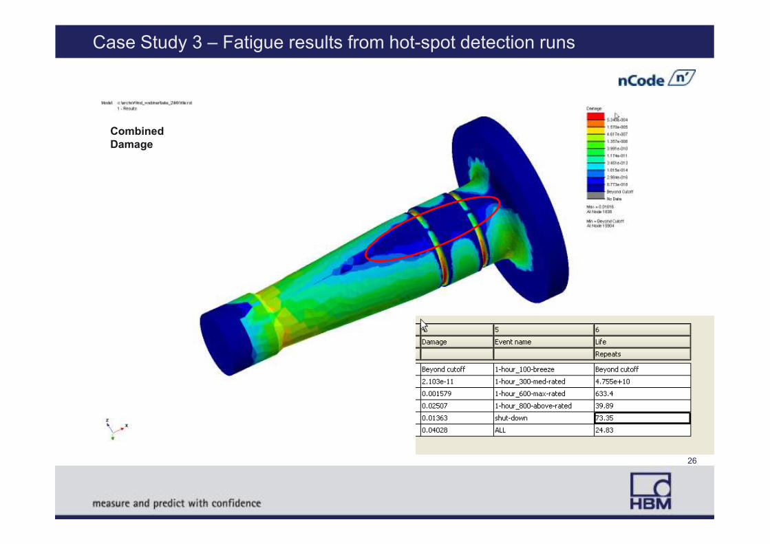
Case Study 3 – Fatigue results from hot-spot detection runs
Combined
Damage
26
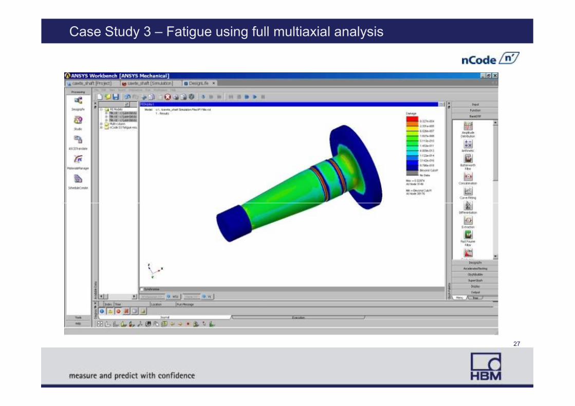
Case Study 3 – Fatigue using full multiaxial analysis
27
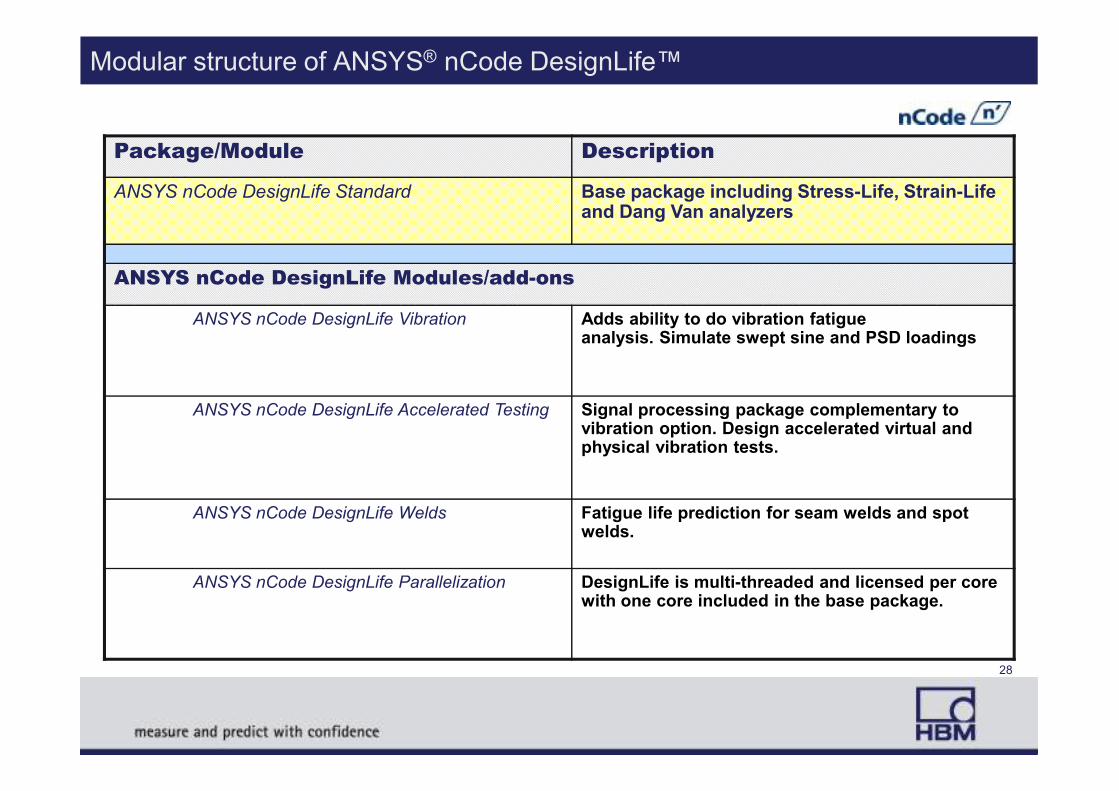
Modular structure of ANSYS® nCode DesignLife™
Package/Module Description
ANSYS nCode DesignLife Standard Base package including Stress-Life, Strain-Life and Dang Van analyzers
ANSYS nCode DesignLife Modules/add-ons
ANSYS nCode DesignLife Vibration Adds ability to do vibration fatigue analysis. Simulate swept sine and PSD loadings
ANSYS nCode DesignLife Accelerated Testing Signal processing package complementary to vibration option. Design accelerated virtual and physical vibration tests.
ANSYS nCode DesignLife Welds Fatigue life prediction for seam welds and spot welds.
ANSYS nCode DesignLife Parallelization DesignLife is multi-threaded and licensed per core with one core included in the base package.
28

Capabilities
• Stress-Life (single, multi-curve, Haigh diagrams)
• Strain-Life (automated multi-axial corrections)
• Multi-axial safety factor (Dang Van)
• Seam welds and spot welds
• High temperature fatigue
• Finite Element results supported
4 Static (linear superposition)
4 Transient
4Modal
ANSYS nCode DesignLife has an extensive scope of fatigue capabilities�
• High temperature fatigue
• Vibration fatigue (shaker simulation)
• Multiple runs in a single analysis
• Complete duty cycles / flight spectrums
• Multi-processor enabled for fast results
• Use Python for proprietary or custom methods
Modal
4 Frequency Response
4 Linear & Non-linear
29

Conclusion
• Introducing nCode ANSYS DesignLife nCode ANSYS DesignLife for ANSYSANSYSTMTM Workbench 13.0Workbench 13.0
• Case Study 1 – Lever Assembly Example4How to do Lifing analysis in Workbench
4Design optimisation based on Life
• Case Study 2 – Wind Turbine Gearbox4What makes a good fatigue analysis?4What makes a good fatigue analysis?
4Element types, mesh quality, stress convergence, support for shells and solids in DesignLife
• Case Study 3 – Wind Turbine Main Shaft4Duty cycle loading in DesignLife
4Multiaxial fatigue considerations
4Selection of critical areas by damage criteria
30
![OPTIMIZATION AND FATIGUE ANALYSISOF A CRANE HOOK …fatigue life contour plots of crane hook using Ansys Workbench and Ansys nCode DesignLife. ... A Gopichand. Et al. [16] studied](https://static.fdocuments.in/doc/165x107/5e2a3a1363a9812dd90d6d8e/optimization-and-fatigue-analysisof-a-crane-hook-fatigue-life-contour-plots-of-crane.jpg)