Quantification of true displacement using apparent displacement

Advanced Design Methods for Offshore Wind Foundations
Professor Byron Byrne Ørsted / Royal Academy of Engineering Research Chair
University of Oxford
Danish Geotechnical Society
7 February 2019
Structural Options
(g)(f)(e)(d)(c)(b)(a)
Images from various websites
Danish Geotechnical Society 7 February 2019
Contact: [email protected] Copyright University of Oxford
Univer
sity o
f Oxfo
rd

Monopile: Monotonic Loading
H
e
D
L
H
vg
Ultimate Load Soil conditions at failure
Initial Loading Small strain soil behaviour Natural frequency is “tuned”
For Monopiles L/D = 2 to 6 e/D = 5 to 15
Photos from Dan Kallehave (Ørsted)
Industrialised Design
Pile length
Wal
l th
ickn
ess
Diameter
L?
t?
D?
Danish Geotechnical Society 7 February 2019
Contact: [email protected] Copyright University of Oxford
Univer
sity o
f Oxfo
rd

Problem Definition
Pile displacement, y
Spring force, p
pu
yc
𝑝(𝑦) = 𝑝𝑢2
𝑦
𝑦𝑐
13
𝑓𝑜𝑟 𝑦 ≤ 8𝑦𝑐
𝑝𝑢 𝑓𝑜𝑟 𝑦 > 8𝑦𝑐
Simplified soil-structure
interaction models allow for the many
calculations needed to optimise wind farm foundations
PISA Project Overview – 2.5 years and £3.5m 3D FE Field Tests
Design
Validate
MG
HG
z v
p(z,v)
m(z,y)
HB(vB) MB(yB)
Simplified 1D
Model
Accurate Response Prediction
Apply
S
Mb
M
H
τ
τ
p
p
z
0
5
10
15
20
0 0.2 0.4 0.6 0.8 1
Ho
rizo
nta
l Lo
ad (
MN
)
Ground Level Displacement (m)
p-y method
3D FE
1D Model
Danish Geotechnical Society 7 February 2019
Contact: [email protected] Copyright University of Oxford
Univer
sity o
f Oxfo
rd

PISA Project Structure and Timetable
Aug 2013 Project start date Nov 2013 Field test tender begins Aug 2014 Design methods Dec 2014 Pile installation Jan 2015 Pile testing start Jul 2015 Pile testing complete Nov 2015 Field test factual results Feb 2016 Close-out workshop May 2016 Final report approved After May 2016 Implementation
Numerical Modelling
Ho
rizo
nta
l Lo
ad
Ground Level Displacement
capacity: - soil conditions at failure
operational loads: - small strain behaviour
0
2
4
6
8
10
12
14
0 50 100 150 200 250 300
De
pth
z(m
)
su TXC (kPa)
TXC - historic data
HSV (PISA)
TXC 38mm (PISA)
TXC 100mm (PISA)
TXC 100mm (GEO)
Simulated
Sand Layer
0
2
4
6
8
10
12
14
0 5 10 15 20
De
pth
, z(m
)
qc (MPa)
Max
Mean
Min
Danish Geotechnical Society 7 February 2019
Contact: [email protected] Copyright University of Oxford
Univer
sity o
f Oxfo
rd

Field Test Campaign – 28 Pile Tests D = 2.0 m
21 m12 m
D = 0.76 m
D = 0.27 m
z
Stick up inclinometer
Load cell
Displacement transducer
Fibre Optic SG
Inclinometer
Extensometer
h
D
L
Test Pile Reaction pile
HG
vG/D (%)0 2 4 6 8 10 12
UL/RL
98
7
65
4
3
2
10
Cowden Test Results: D = 2 m , L/D = 5.25
0
0.5
1
1.5
2
2.5
0 50 100 150 200
Ho
rizo
nta
l Lo
ad (
MN
)
Ground Level Displacement (mm)
0.1D
p-y method
3DFE
Field Test
Danish Geotechnical Society 7 February 2019
Contact: [email protected] Copyright University of Oxford
Univer
sity o
f Oxfo
rd

PISA Design Model
MG
HG
Tower
Ground level
Mon
opile
Distributed lateral load
Vertical shear stresses at pile/
soil interface
Shear force and moment applied at the pile base.
MG
HG
Tower
Ground level
Distributed lateral load,
p(z,v)
Distributed moment m(z,y)
z
v
HB(vB)
MB(yB)
Timoshenko beam finite elements
3D Finite Element Modelling Extract Information
Normalise and Parameterise
k
yu
xu
n
y u 0
5
10
15
20
0 0.2 0.4 0.6 0.8 1
H (
MN
)
vG (m)
Apply to 1D Model
Design Case: L/D = 4, M/HD = 10 and D = 8.75m
Calibration (11 Calculations) D = 5, 7.5, 10 m
L/D = 2, 6 M/HD = 5, 15
t/D = 60, 80, 110 Design Improved from L/D = 6.2 to L/D = 4: SAVING = 35%!
0
2
4
6
8
10
12
14
16
0 2 4 6 8 10
M/H
D
L/D
Calibration cases
Design cases
0
5
10
15
20
25
30
0 0.2 0.4 0.6 0.8 1
Ho
rizo
nta
l Lo
ad (
MN
)
Ground Level Displacement (m)
0.1D
p-y: L/D = 6.2
p-y: L/D = 4
1D Model
3DFE
Danish Geotechnical Society 7 February 2019
Contact: [email protected] Copyright University of Oxford
Univer
sity o
f Oxfo
rd
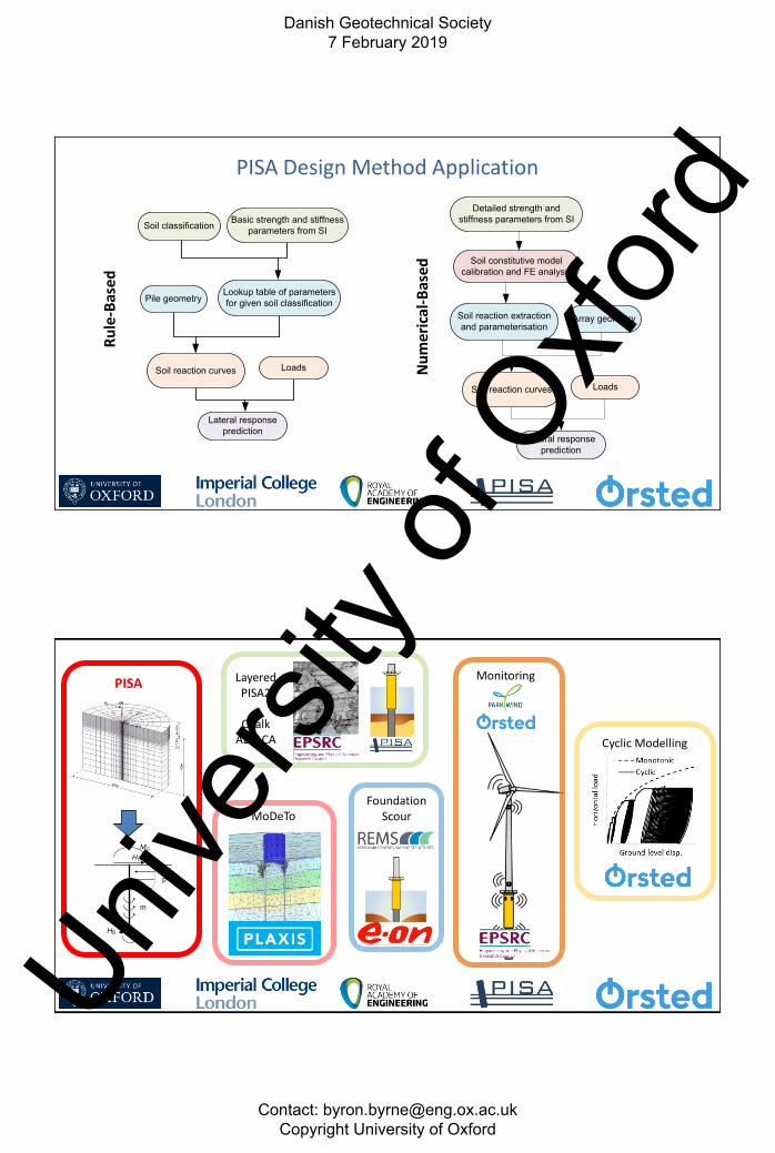
PISA Design Method Application
Lateral response prediction
Soil classification Basic strength and stiffness parameters from SI
Lookup table of parameters for given soil classification
Soil reaction curves
Pile geometry
Loads
Detailed strength and stiffness parameters from SI
Soil reaction extraction and parameterisation
Soil reaction curves
Array geometry
Loads
Lateral response prediction
Soil constitutive model calibration and FE analysis
Ru
le-B
ased
Nu
mer
ical
-Bas
ed
MG
HG
p
m
HB
MB
PISA Layered PISA2
Chalk
ALPACA
Foundation Scour
Cyclic Modelling
Monitoring
MoDeTo
Danish Geotechnical Society 7 February 2019
Contact: [email protected] Copyright University of Oxford
Univer
sity o
f Oxfo
rd

PLAXIS Monopile Design Tool: MoDeTo
• Commercial application of PISA Method by PLAXIS
– Collaboration with Oxford University and Fugro
• Validated against experimental results from both test sites
• Rule-based and numerical-based design using user-defined or automatically calibrated soil response curves
– Rule-based: Stand-alone tool. User-defined SRC
– Numerical-based: SRC calibration from PLAXIS 3D FE model
• More info: http://www.plaxis.com/modeto
e
C)(A) (E/F)
dt
(B) (
d=L/2dt
(D)
e
(PC)
PISA Phase 2 Layered Soils
PISA Phase 2 London clay
Bothkennar clay
Dunkirk sand (relative density 45%, 60%, 90%
Calibrated 1D model
(a) Application to Layered Soil Homogeneous Soils
(b) General Dunkirk Sand Model
e
C)(A) (E/F)
dt
(B) (
d=L/2dt
(D)
e
(PC)
PISA Phase 1 Cowden till
Dunkirk sand
(relative density 75%)
Danish Geotechnical Society 7 February 2019
Contact: [email protected] Copyright University of Oxford
Univer
sity o
f Oxfo
rd

Example PISA Phase 2 Output Pile D2: D=8.75 m, L/D=4, h=87.5 m, t=91 mm
0
0.1
0.2
0.3
0.4
0.5
0 0.0004375 0.000875H
(M
N)
vG (m)
Small displacement
0
5
10
15
20
25
30
35
40
0 0.4375 0.875
H (
MN
)
vG (m)
Ultimate response
-35
-25
-15
-5
0 1750 3500
De
pth
(m
)
Bending Moment (MNm)
Hult/2Hult
020 0.005 0.01H
( M
vG (m)Small displacement3D FE 1D (parametric)
0
5
10
15
20
25
30
35
40
0.74
0.78
0.82
0.86
0.90
0.94
0.98
1.02
1.06
1.10
1.14
1.18
1.22
1.26
1.30
1.34
1.38
1.42
1.46
1.50
1.54
Fre
qu
en
cy
Load (1D Model) / Load (3D FE)
Layered
Homogeneous
Mean = 1.01 CoV = 4.7%
0
5
10
15
20
25
30
35
0.74
0.78
0.82
0.86
0.90
0.94
0.98
1.02
1.06
1.10
1.14
1.18
1.22
1.26
1.30
1.34
1.38
1.42
1.46
1.50
1.54
Fre
qu
en
cy
Load (1D Model) / Load (3D FE)
Layered
Homogeneous
Mean = 1.01 CoV = 7.2%
PISA Phase 2 Summary
Danish Geotechnical Society 7 February 2019
Contact: [email protected] Copyright University of Oxford
Univer
sity o
f Oxfo
rd

• A number of conference papers available including keynote for the 2017 London SUT OSIG conference.
• An overview paper will be presented at 2019 OTC
• 8 Papers on the field testing / numerical modelling / design methods submitted for journal publication – 5 now accepted for publication in Géotechnique
– 3 under review
• Papers to come through in the near future include: – Papers on the cyclic loading field tests
– Papers reporting the PISA Phase 2 project
PISA Publications
Application to Suction Caissons (Suryasentana 2018)
• Similar Winkler framework as PISA (but 6DoF loading)
• OxCaisson: Family of fast design methods calibrated by 3D FE
– FLS analysis in linear elastic soil
– SLS analysis in non-linear elastic soil
– ULS analysis in elasto-plastic soil
Displacement
Load
FLS SLS ULS
PlasticNon-linear Elasticor
Elasto-Plastic
Linearelastic
Danish Geotechnical Society 7 February 2019
Contact: [email protected] Copyright University of Oxford
Univer
sity o
f Oxfo
rd

Monopile Cyclic Loading: Basics
H
vg
H
vg
One Way Loading
Two Way Loading
• Monotonic loading response is an essential input for any cyclic loading calculation
• Cyclic loading models must capture hysteresis, ratcheting behaviour and stiffness change
• Ultimate capacity after cycling • Cyclic loading is irregular / pseudo random
Cyclic Testing
Danish Geotechnical Society 7 February 2019
Contact: [email protected] Copyright University of Oxford
Univer
sity o
f Oxfo
rd

Cyclic Results from PISA – Current Design Approach (?)
Lo
ad
Displacement
Backbone ResponsePISA or p-y calculation
Factored Response for Cyclic Behaviour
• Hyperplasticity , an approach to plasticity theory based on thermodynamic principles, developed by Prof. Guy Houlsby and Prof. Sasha Puzrin
• Entire model specified by just two functions with output derived using standard mathematical procedures
• Can be applied at 0D macro model, 1D generalised Winkler model or at the 3D continuum level
Hyperplastic Accelerated Ratcheting Model (HARM)
E0
E1
E2
ENs
e
s
e1 e2 eNs
s1
s2
sNs
H0
s
e
k1
H1
kNs
HNs
aNs a1
R
ar
q
M
N cycles
10N cycles
Danish Geotechnical Society 7 February 2019
Contact: [email protected] Copyright University of Oxford
Univer
sity o
f Oxfo
rd

Modelling for Cyclic Loading (0D): HARM (Abadie 2015)
0
0.2
0.4
0.6
0.8
0 0.1 0.2 0.3 0.4 0.5 0.6
No
rmalised
Ho
rizo
nta
l L
oad
Normalised Ground Displacement
0
0.2
0.4
0.6
0.8
0 0.1 0.2 0.3 0.4 0.5 0.6
No
rmalised
Ho
rizo
nta
l L
oad
Normalised Ground Displacement
H
e
D
L
Modelling Results from PISA (1D): HARM (Beuckelaers 2017)
Danish Geotechnical Society 7 February 2019
Contact: [email protected] Copyright University of Oxford
Univer
sity o
f Oxfo
rd

Multidirectional Loading
Laboratory Model Tests (Richards 2019)
Danish Geotechnical Society 7 February 2019
Contact: [email protected] Copyright University of Oxford
Univer
sity o
f Oxfo
rd

Realistic Storm Loading – Laboratory (Richards 2019)
Application of HARM to Storm Loading (Balaam 2020)
0
0.25
0.5
0.75
1
0 0.25 0.5 0.75 1
σcy
c/σ
REF
|σav|/σREF
Danish Geotechnical Society 7 February 2019
Contact: [email protected] Copyright University of Oxford
Univer
sity o
f Oxfo
rd

• Develop new geotechnical design methods for offshore wind turbine foundations with a focus on – Cyclic loading including ratcheting effects
– Loading rate effects
– Robust calibration process
– Benchmark with field scale pile testing
• Translation into industrial practice for Ørsted
• Design optimisation for future wind farms
• Dissemination
Oxford – Ørsted Collaboration 2018-2023
WP1: Modelling
S
Mb
M
H
τ
τ
p
p
z
WP2: Calibration Methods
0
0.2
0.4
0.6
0.8
0 0.1 0.2 0.3 0.4 0.5 0.6
No
rmalised
Ho
rizo
nta
l L
oad
Normalised Ground Displacement
WP3: Theoretical Methods WP4: Field Testing
WP5: Application to Design
Oxford – Ørsted Collaboration 2018-2023
Danish Geotechnical Society 7 February 2019
Contact: [email protected] Copyright University of Oxford
Univer
sity o
f Oxfo
rd

Oxford – Ørsted Collaboration 2018-2023
Non-Funded Research StudentsToby Balaam (WP2, WP3), Bohan Chen (CSC)
Iona Richards (WP2, WP3), Jonathan White (WP2)
Principal InvestigatorByron Byrne
Funded Research StudentsSarah Martin (WP4), Mark Qiu (WP2)Luc Simonin (WP3), Wayne Wu (WP2)
2 Students for October 2019
Post Doctoral Researchers / OthersStephen Suryasentana (WP1)PDRA to be appointed (WP4)
Clive Baker (Technician)
Oxford Academic TeamRóisín Buckley (WP2, WP4), Harvey Burd (WP1, WP3)Guy Houlsby (WP2, WP3), Chris Martin (WP2, WP3)
Ross McAdam (WP4), Brian Sheil (WP4)
Field Test Contractor(WP4)
To be Appointed
ØrstedJens Gengenbach (Contract), Amin Aghakouchak (Technical)
Chris Rogers (Contracts), Anne Petersen (R&D PM)
• Offshore wind energy is a major part of the UK Energy mix and will be for the foreseeable future
• Civil and geotechnical engineering is making significant contributions to offshore wind turbine design
• New approaches have been developed to more accurately design laterally loaded monopiles to allow site-wide optimisation
• Cyclic loading is the most significant challenge to address and is the focus of current efforts across the industry
• Oxford and Ørsted are collaborating to develop the next generation of design models to address cyclic loading
Concluding Remarks
Danish Geotechnical Society 7 February 2019
Contact: [email protected] Copyright University of Oxford
Univer
sity o
f Oxfo
rd

The PISA Project was funded through the joint industry Offshore Wind Accelerator (OWA) program, designed and led by the Carbon Trust, with PISA Phase 1 supported by the UK Department for Energy and Climate Change (DECC) and PISA Phase 2 supported by the
Scottish Government.
Financial and technical support was provided by the following project partners: Ørsted (lead partner), E.ON, EDF, GE Renewable Energy, Iberdrola, innogy, SSE, Statkraft (Phase 1 only),
Equinor, Van Oord and Vattenfall.
The PISA Project Academic Work Group and numerous other people working for companies that supported the PISA Project.
Dr C.N. Abadie, T. Balaam, Dr W.P.A.J. Beuckelaers, I.A. Richards, Dr S.K. Suryasentana
For the Oxford-Ørsted collaboration the generous support of Ørsted, the UK’s Royal
Academy of Engineering and the University of Oxford is acknowledged.
Acknowledgements
Suction Installed Caissons – Guidelines – Out Shortly
𝐻
ℎ0𝑉0
2
+𝑀
𝑚0𝐷𝑉0
2
−2𝑎𝐻𝑀
ℎ0𝑚0𝐷𝑉02 − 4
𝑉
𝑉01 −
𝑉
𝑉0= 0
Mono-Caisson Multi-Caisson
L
Ds
L
D
Danish Geotechnical Society 7 February 2019
Contact: [email protected] Copyright University of Oxford
Univer
sity o
f Oxfo
rd