Advanced Course VO1NO - avarc.ca
198
Advanced Course VO1NO Transmission Lines 1
Transcript of Advanced Course VO1NO - avarc.ca
Advanced Course
VO1NO
Transmission Lines
1

Transmission Lines
• Enable signals from the radio to reach the
antenna and vice versa.
• Also known as feeders or feedlines.
• Transmission Lines have 2 ends:
– Source: where the power enters the feedline.
– Load: where the power is transferred into a device
or antenna.
Al Penney
VO1NO
In radio-frequency engineering, a transmission line is a specialized cable or
other structure designed to conduct alternating current of radio frequency, that
is, currents with a frequency high enough that their wave nature must be taken
into account. Transmission lines are used for purposes such as connecting radio transmitters and receivers with their antennas (they are then
called feed lines or feeders), distributing cable
television signals, trunklines routing calls between telephone switching centres,
computer network connections and high speed computer data buses.
Ordinary electrical cables suffice to carry low frequency alternating
current (AC), such as mains power, which reverses direction 100 to 120 times
per second, and audio signals. However, they cannot be used to carry currents
in the radio frequency range, above about 30 kHz, because the energy tends to
radiate off the cable as radio waves, causing power losses. Radio frequency
currents also tend to reflect from discontinuities in the cable such as connectors and joints, and travel back down the cable toward the
source. These reflections act as bottlenecks, preventing the signal power from
reaching the destination. Transmission lines use specialized construction, and impedance matching, to carry electromagnetic signals with minimal
reflections and power losses. The distinguishing feature of most transmission lines is that they have uniform cross sectional dimensions along their length,

giving them a uniform impedance, called the characteristic impedance, to
prevent reflections. Types of transmission line include parallel line (ladder line, twisted pair), coaxial cable, and planar transmission lines such
as stripline and microstrip. The higher the frequency of electromagnetic waves
moving through a given cable or medium, the shorter the wavelength of the
waves. Transmission lines become necessary when the transmitted
frequency's wavelength is sufficiently short that the length of the cable
becomes a significant part of a wavelength.
At microwave frequencies and above, power losses in transmission lines
become excessive, and waveguides are used instead, which function as
"pipes" to confine and guide the electromagnetic waves. Some sources define
waveguides as a type of transmission line; however, this article will not include
them. At even higher frequencies, in the terahertz, infrared and visible ranges,
waveguides in turn become lossy, and optical methods, (such as lenses and
mirrors), are used to guide electromagnetic waves.
2

Optimum Transmission Line
• Does not radiate signal from the line itself.
• No loss of signal passing through the line.
• Constant electrical characteristics throughout
its length.
• Unfortunately, there is no such thing as an
ideal transmission line!
Al Penney
VO1NO
3

Al Penney
VO1NO
4

• A feedline has inductance and capacitance distributed along its
length.
• This offers reactance to AC in the feedline.
• Value of Capacitive and Inductive Reactance vary in opposite
directions as frequency changes.
• This causes the impedance to remain the same over a wide
range of frequencies.
• This is the Characteristic or Surge Impedance.
Characteristic Impedance
Al Penney
VO1NO
CHARACTERISTIC IMPEDANCE
If the line could be “perfect”—having no resistive losses—a question might arise:
What is the amplitude of the current in a pulse applied to this line? Will a larger
voltage result in a larger current, or
is the current theoretically infinite for an applied voltage, as we would expect from
applying Ohm’s Law to a circuit without resistance? The answer is that the current
does depend directly on the voltage,
just as though resistance were present. The reason for this is that the current flowing
in the line is something like the charging current that flows when a battery is
connected to a capacitor. That is, the line has capacitance. However, it also has
inductance. Both of these are “distributed” properties. We may think of the line as
being composed of a whole series of small inductors and capacitors, connected as in
the figure, where each coil is the inductance of an extremely small section of wire,
and the capacitance is that existing between the same two sections. Each series
inductor acts to limit the rate at which current can charge the following shunt
capacitor, and in so doing establishes a very important property of a transmission line:
its surge impedance, more commonly known as its characteristic impedance. This is
abbreviated by convention as Z0.

Characteristic Impedance
• Abbreviated Zo
• Value depends on
– the physical dimensions of the line; and
– The relative positions of the conductors.
• Zo = ratio of voltage to current at any given
point.
• Value does not depend on length.
Al Penney
VO1NO
6

Characteristic Impedance
• Characteristic Impedance is an AC effect –
you cannot measure it using DC.
• Actual resistance losses are called Copper
Losses.
• Skin Effect causes higher losses as frequency
increases.
Al Penney
VO1NO
7

Skin Effect
• Tendency of AC to become distributed within a conductor such that the current density is largest near the surface of the conductor, and decreases with greater depths in the conductor.
• The electric current flows mainly at the "skin" of the conductor, between the outer surface and a level called the skin depth.
• The skin effect causes the effective resistance to increase at higher frequencies where the skin depth is smaller, thus reducing the effective cross-section of the conductor.
Al Penney
VO1NO
Skin effect is the tendency of an alternating electric current (AC) to become
distributed within a conductor such that the current density is largest near the
surface of the conductor, and decreases with greater depths in the conductor.
The electric current flows mainly at the "skin" of the conductor, between the outer surface and a level called the skin depth. The skin effect causes the
effective resistance of the conductor to increase at higher frequencies where
the skin depth is smaller, thus reducing the effective cross-section of the conductor. The skin effect is due to opposing eddy currents induced by the
changing magnetic field resulting from the alternating current. At
60 Hz in copper, the skin depth is about 8.5 mm. At high frequencies the skin
depth becomes much smaller. Increased AC resistance due to the skin effect can be mitigated by using specially woven litz wire. Because the interior of a
large conductor carries so little of the current, tubular conductors such as pipe can be used to save weight and cost.

Al Penney
VO1NO
9

Balanced Transmission Line
• Currents are equal but in opposite direction.
• This cancels the EM field.
• Therefore very little radiation from the line.
Source Load
Al Penney
VO1NO
At radio frequencies, every conductor that has appreciable length compared with the
wavelength in use radiates power¾every conductor is an antenna. Special care must
be used, therefore, to minimize
radiation from the conductors used in RF transmission lines. Without such care, the
power radiated by the line may be much larger than that which is lost in the resistance
of conductors and dielectrics
(insulating materials). Power loss in resistance is inescapable, at least to a degree, but
loss by radiation is largely avoidable.
Radiation loss from transmission lines can be prevented by using two conductors
arranged and operated so the electromagnetic field from one is balanced everywhere
by an equal and opposite field
from the other. In such a case, the resultant field is zero everywhere in space¾there is
no radiation from the line. For example, two parallel conductors having currents I1
and I2 flowing in opposite
directions. If the current I1 at point Y on the upper conductor has the same amplitude
as the current I2 at the corresponding point X on the lower conductor, the fields set up
by the two currents are equal in
magnitude. Because the two currents are flowing in opposite directions, the field from
I1 at Y is 180 out of phase with the field from I2 at X. However, it takes a measurable
interval of time for the field

from X to travel to Y. If I1 and I2 are alternating currents, the phase of the field from
I1 at Y changes in such a time interval, so at the instant the field from X reaches Y, the
two fields at Y are not exactly 180
out of phase. The two fields are exactly 180 out of phase at every point in space only
when the two conductors occupy the same space¾an obviouslyimpossible condition if
they are to remain separate
conductors.
The best that can be done is to make the two fields cancel each other as completely as
possible. This can be achieved by keeping the distance between the two conductors
small enough so the
time interval during which the field from X is moving to Y is a very small part of a
cycle. When this is the case, the phase difference between the two fields at any given
point is so close to 180
that cancellation is nearly complete.
Practical values of d (the separation between the two conductors) are determined by
the physical limitations of line construction. A separation that meets the condition of
being “very small” at one frequency may be quite large at another. For example,
if d is 6 inches, the phase difference between the two fields at Y is only a fraction of a
degree if the frequency is 3.5 MHz. This is because a distance of 6 inches is such a
small fraction of a wavelength
(1 l = 281 feet) at 3.5 MHz. But at 144 MHz, the phase difference is 26, and at 420
MHz, it is 77. In neither of these cases could the two fields be considered to “cancel”each other. Conductor separation
must be very small in comparison with the wavelength used; it should never exceed
1% of the wavelength, and smaller separations are desirable. Transmission lines
consisting of two parallel conductors
as in Fig 1A are called open-wire lines, parallel-conductor lines or two-wire lines.
10

Open Wire Feedline
• Two parallel wires separated (mostly) by air.
• Insulated spacers maintain distance.
• Characteristic Impedances 200 – 600 Ohms.
Al Penney
VO1NO
Parallel feeders go back to the beginnings of radio. By 1930, the "two-wire untuned
feeder system" was a standard ARRL Handbook feature. The Jones Radio
Handbook of 1937 provides a table of line losses showing the advantages of open-wire
feeders (a 440-Ohm line in the table) over lower impedance twisted-pair feeders (p.
70). The use of 600-Ohm lines was fairly standard, using a spacing of about 6". "To
reduce radiation from the feeders to a minimum, the two wires should not be more
than 10 to 12 inches apart." (The Radio Amateur's Handbook, 7th Ed., ARRL, 1930, p.
162) Rarely did hams exceed the 6" spacing.
Every transmission line has a characteristic impedance, and parallel transmission lines
are no exception. The characteristic impedance (Zo) of a line depends on the physical
properties of the line. For a 2-wire set, we have only two properties of note (assuming
the use of a very conductive material, such as copper): the diameter of the wire and
the spacing between the wires.
Twin lead is a form of parallel-wire balanced transmission line. The separation
between the two wires in twin-lead is small compared to the wavelength of
the radio frequency (RF) signal carried on the wire.[3] The RF current in one
wire is equal in magnitude and opposite in direction to the RF current in the other wire. Therefore, in the far field region far from the transmission line,
the radio waves radiated by one wire are equal in magnitude but opposite in
phase (180° out of phase) to the waves radiated by the other wire, so

they superpose and cancel each other. The result is that almost no net radio
energy is radiated by the line.
Similarly, any interfering external radio waves will induce equal, in phase RF
currents, traveling in the same direction, in the two wires. Since the load at the destination end is connected across the wires, only differential, oppositely-
directed currents in the wires create a current in the load. Thus the interfering
currents are canceled out, so twin lead does not tend to pick up radio noise.
However, if a piece of metal is located sufficiently close to a twin-lead line,
within a distance comparable to the wire spacing, it will be significantly closer
to one wire than the other. As a result, the RF current induced in the metal
object by one wire will be greater than the opposing current induced by the
other wire, so the currents will no longer cancel. Thus nearby metal objects
can cause power losses in twin lead lines, through energy dissipated as heat
by induced currents. Similarly, radio noise originating in cables or metal objects
located near the twin-lead line can induce unbalanced currents in the wires,
coupling noise into the line.
In order to prevent power from being reflected from the load end of the line, causing high SWR and inefficiency, the load must have an impedance which
matches the characteristic impedance of the line. This causes the load to
appear electrically identical to a continuation of the line, preventing reflections.
Similarly, to transfer power efficiently into the line, the source must also match
the characteristic impedance. To connect balanced transmission line to unbalanced line like coaxial cable, a device called a balun must be used.
11
Insulated Twin Lead
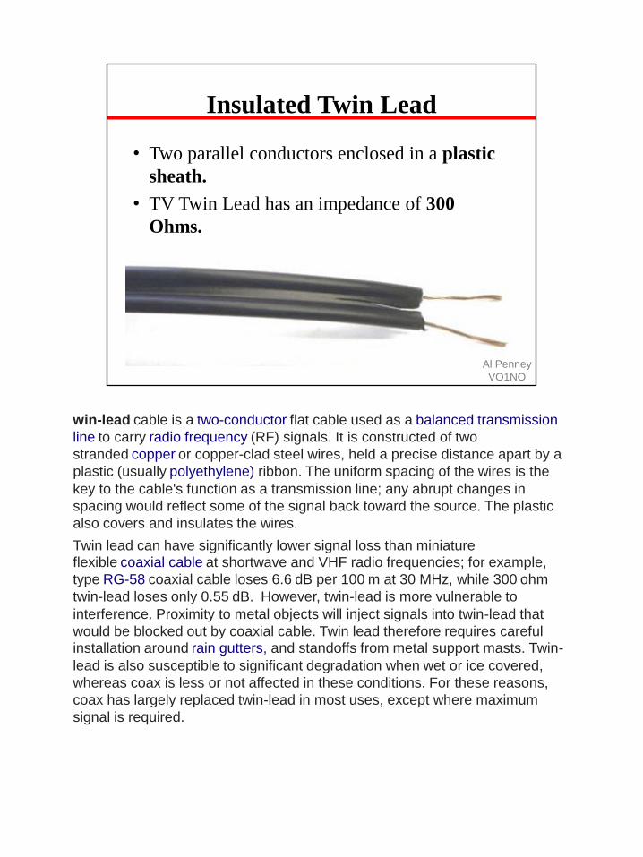
• Two parallel conductors enclosed in a plastic
sheath.
• TV Twin Lead has an impedance of 300
Ohms.
Al Penney
VO1NO
win-lead cable is a two-conductor flat cable used as a balanced transmission
line to carry radio frequency (RF) signals. It is constructed of two
stranded copper or copper-clad steel wires, held a precise distance apart by a
plastic (usually polyethylene) ribbon. The uniform spacing of the wires is the
key to the cable's function as a transmission line; any abrupt changes in
spacing would reflect some of the signal back toward the source. The plastic
also covers and insulates the wires.
Twin lead can have significantly lower signal loss than miniature flexible coaxial cable at shortwave and VHF radio frequencies; for example,
type RG-58 coaxial cable loses 6.6 dB per 100 m at 30 MHz, while 300 ohm
twin-lead loses only 0.55 dB. However, twin-lead is more vulnerable to
interference. Proximity to metal objects will inject signals into twin-lead that
would be blocked out by coaxial cable. Twin lead therefore requires careful installation around rain gutters, and standoffs from metal support masts. Twin-
lead is also susceptible to significant degradation when wet or ice covered,
whereas coax is less or not affected in these conditions. For these reasons,
coax has largely replaced twin-lead in most uses, except where maximum
signal is required.

Ladder Line
• Variant of Insulated Twin Lead.
• To reduce losses, some of the plastic is cut
away.
• Characteristic Impedance of 450 Ohms.
Al Penney
VO1NO
Ladder line or "window line" is a variation of twin lead which is constructed
similarly, except that the polyethylene webbing between the wires which holds them apart has rectangular openings ("windows") cut in it. The line consists of
two insulated wires with "rungs" of plastic holding them together every few inches, giving it the appearance of a ladder. The advantage of the "windows"
is that they lighten the line, and also reduce the amount of surface on which
dirt and moisture can accumulate, making ladder line less vulnerable to weather-induced changes in characteristic impedance. The most common
type is 450 ohm ladder line, which has a conductor spacing of about an inch.

Characteristic Impedance
Al Penney
VO1NOD
(dielectric constant)
Identical units of measurement must be used in both terms of the fraction.
k = dielectric constant of insulation between conductors. For air it is 1.00059 (round off to 1 for practical applications).
The dielectric constant k is the relative permittivity of a dielectric material. It is an
important parameter in characterizing capacitors. It is unfortunate that the same
symbol k is often used for Coulomb's constant, so one must be careful of this possible
confusion.
The relative permittivity of a material is its (absolute) permittivity expressed
as a ratio relative to the vacuum permittivity.
Permittivity is a material property that affects the Coulomb force between two
point charges in the material. Relative permittivity is the factor by which the
electric field between the charges is decreased relative to vacuum.
Likewise, relative permittivity is the ratio of the capacitance of a capacitor using
that material as a dielectric, compared with a similar capacitor that has vacuum
as its dielectric. Relative permittivity is also commonly known as the dielectric
constant, a term still used but deprecated by standards organizations in engineering as well as in chemistry.

Advantages of Balanced Line
• Lower losses at high SWR than coax cable.
• Can be made at home.
• Often cheaper than coax cable.
• Permits multi-band antennas
Al Penney
VO1NO
Open-wire line has the advantage of both lower loss and lower cost compared to coax.
600-W open-wire line at 30 MHz has a matched loss of only 0.1 dB. If you use such
open-wire
line with the same 5:1 SWR, the total loss would still be less than 0.3 dB. In fact, even
if the SWR rose to 20:1, the total loss would be less than 1 dB. Typical open-wire line
sells for about 1/3 the cost of good quality coax cable.
Open-wire line is enjoying a renaissance of sorts with amateurs wishing to cover
multiple HF bands with a single-wire antenna. This is particularly true since the bands
at 30, 17 and 12 meters
became available in the early 1980s. The 102-foot long “G5RV dipole,” fed with
open-wire ladder line into an antenna tuner, has become popular as a simple all-band
antenna. The simple 130-foot long flattop
dipole, fed with open-wire 450-W “window” ladder-line, is also very popular among
all-band enthusiasts.
Despite their inherently low-loss characteristics, open-wire lines are not often
employed above about 100 MHz. This is because the physical spacing between the
two wires begins to become an
appreciable fraction of a wavelength, leading to undesirable radiation by the line
itself. Some form of coaxial cable is almost universally used in the VHF and UHF
amateur bands.

Disadvantages of Balanced Line
• Spacing must be kept constant.
• Cannot be buried, laid on ground, or run alongside a conductor.
• Impedance varies in rain and with icing.
• Safety hazard if touched while transmitting.
• Impedance higher than radio antenna terminal, so an impedance matching device is necessary.
• Spacing on VHF/UHF is an appreciable fraction of the wavelength, so line radiates.
Al Penney
VO1NO
16

17

18

Unbalanced Transmission Line
• One conductor at ground potential, the other
carrying RF.
• Usually called Coaxial Cable, or “Coax”.
• Most common type of feedline.
Al Penney
VO1NO
An unbalanced line is a transmission line, often coaxial cable, whose
conductors have unequal impedances with respect to ground; as opposed to
a balanced line. Microstrip and single-wire lines are also unbalanced lines.
Any line that has a different impedance of the return path may be considered
an unbalanced line. However, unbalanced lines usually consist of a conductor that is considered the signal line and another conductor that is grounded, or is
ground itself. The ground conductor often takes the form of a ground plane or
the screen of a cable. The ground conductor may be, and often is, common to
multiple independent circuits. For this reason the ground conductor may be referred to as common.
A coaxial line (coax) has a central signal conductor surrounded by a cylindrical
shielding conductor. The shield conductor is normally grounded. The coaxial format was developed during World War II for use in radar. It was originally
constructed from rigid copper pipes, but the usual form today is a flexible cable
with a braided screen. The advantages of coax are a theoretically perfect electrostatic screen and highly predictable transmission parameters.
The latter is a result of the fixed geometry of the format which leads to a
precision not found with loose wires. Open wire systems are also affected by
nearby objects altering the field pattern around the conductor. Coax does not
suffer from this since the field is entirely contained within the cable due to the
surrounding screen.

Coaxial lines are the norm for connections between radio transmitters and their antennae, for interconnection of electronic equipment where high
frequency or above is involved, and were formerly widely used for forming local
area networks before twisted pair became popular for this purpose.
Triaxial cable (triax) is a variant of coax with a second shield conductor
surrounding the first with a layer of insulation in between. As well as providing
additional shielding, the outer conductors can be used for other purposes such as providing power to equipment or control signals. Triax is widely used for the
connection of cameras in television studios.
19
Al Penney
VO1NO
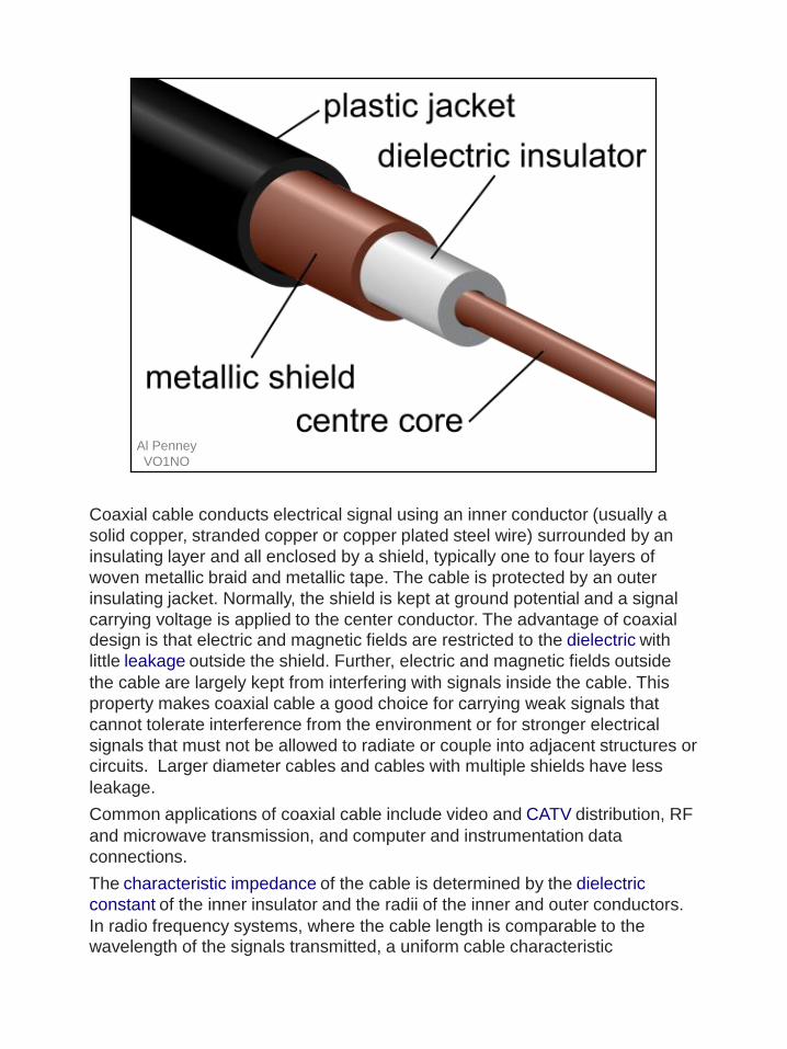
Coaxial cable conducts electrical signal using an inner conductor (usually a
solid copper, stranded copper or copper plated steel wire) surrounded by an
insulating layer and all enclosed by a shield, typically one to four layers of
woven metallic braid and metallic tape. The cable is protected by an outer
insulating jacket. Normally, the shield is kept at ground potential and a signal
carrying voltage is applied to the center conductor. The advantage of coaxial design is that electric and magnetic fields are restricted to the dielectric with
little leakage outside the shield. Further, electric and magnetic fields outside
the cable are largely kept from interfering with signals inside the cable. This
property makes coaxial cable a good choice for carrying weak signals that
cannot tolerate interference from the environment or for stronger electrical
signals that must not be allowed to radiate or couple into adjacent structures or circuits. Larger diameter cables and cables with multiple shields have less
leakage.
Common applications of coaxial cable include video and CATV distribution, RF
and microwave transmission, and computer and instrumentation data
connections.
The characteristic impedance of the cable is determined by the dielectric
constant of the inner insulator and the radii of the inner and outer conductors.
In radio frequency systems, where the cable length is comparable to the wavelength of the signals transmitted, a uniform cable characteristic

impedance is important to minimize loss. The source and load impedances are
chosen to match the impedance of the cable to ensure maximum power
transfer and minimum standing wave ratio. Other important properties of
coaxial cable include attenuation as a function of frequency, voltage handling
capability, and shield quality.
20
Al Penney
VO1NO
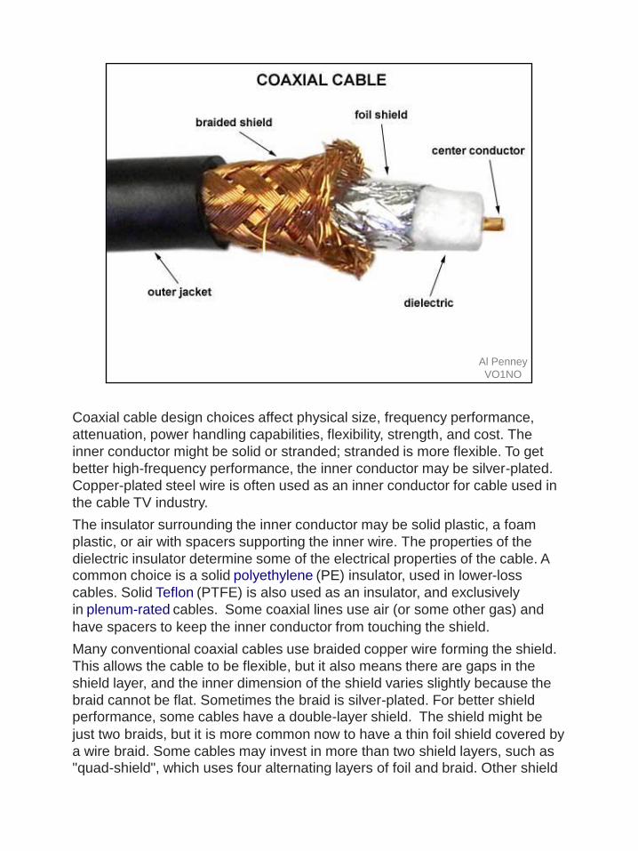
Coaxial cable design choices affect physical size, frequency performance,
attenuation, power handling capabilities, flexibility, strength, and cost. The
inner conductor might be solid or stranded; stranded is more flexible. To get
better high-frequency performance, the inner conductor may be silver-plated.
Copper-plated steel wire is often used as an inner conductor for cable used in
the cable TV industry.
The insulator surrounding the inner conductor may be solid plastic, a foam
plastic, or air with spacers supporting the inner wire. The properties of the
dielectric insulator determine some of the electrical properties of the cable. A common choice is a solid polyethylene (PE) insulator, used in lower-loss
cables. Solid Teflon (PTFE) is also used as an insulator, and exclusively
in plenum-rated cables. Some coaxial lines use air (or some other gas) and
have spacers to keep the inner conductor from touching the shield.
Many conventional coaxial cables use braided copper wire forming the shield.
This allows the cable to be flexible, but it also means there are gaps in the
shield layer, and the inner dimension of the shield varies slightly because the
braid cannot be flat. Sometimes the braid is silver-plated. For better shield performance, some cables have a double-layer shield. The shield might be
just two braids, but it is more common now to have a thin foil shield covered by
a wire braid. Some cables may invest in more than two shield layers, such as "quad-shield", which uses four alternating layers of foil and braid. Other shield

designs sacrifice flexibility for better performance; some shields are a solid
metal tube. Those cables cannot be bent sharply, as the shield will kink,
causing losses in the cable. When a foil shield is used a small wire conductor
incorporated into the foil makes soldering the shield termination easier.
For high-power radio-frequency transmission up to about 1 GHz, coaxial cable
with a solid copper outer conductor is available in sizes of 0.25 inch upward.
The outer conductor is corrugated like a bellows to permit flexibility and the
inner conductor is held in position by a plastic spiral to approximate an air dielectric. One brand name for such cable is Heliax.
Coaxial cables require an internal structure of an insulating (dielectric) material
to maintain the spacing between the center conductor and shield. The dielectric losses increase in this order: Ideal dielectric (no loss), vacuum,
air, polytetrafluoroethylene (PTFE), polyethylene foam, and solid polyethylene.
A low relative permittivity allows for higher-frequency usage. An
inhomogeneous dielectric needs to be compensated by a non-circular
conductor to avoid current hot-spots.
While many cables have a solid dielectric, many others have a foam dielectric
that contains as much air or other gas as possible to reduce the losses by
allowing the use of a larger diameter center conductor. Foam coax will have
about 15% less attenuation but some types of foam dielectric can absorb moisture—especially at its many surfaces — in humid environments,
significantly increasing the loss. Supports shaped like stars or spokes are even
better but more expensive and very susceptible to moisture infiltration. Still
more expensive were the air-spaced coaxials used for some inter-city
communications in the mid-20th century. The center conductor was suspended
by polyethylene discs every few centimeters. In some low-loss coaxial cables
such as the RG-62 type, the inner conductor is supported by a spiral strand of
polyethylene, so that an air space exists between most of the conductor and the inside of the jacket. The lower dielectric constant of air allows for a greater
inner diameter at the same impedance and a greater outer diameter at the same cutoff frequency, lowering ohmic losses. Inner conductors are
sometimes silver-plated to smooth the surface and reduce losses due to skin
effect. A rough surface extends the current path and concentrates the current
at peaks, thus increasing ohmic loss.
The insulating jacket can be made from many materials. A common choice is PVC, but some applications may require fire-resistant materials. Outdoor
applications may require the jacket to resist ultraviolet light, oxidation, rodent
damage, or direct burial. Flooded coaxial cables use a water blocking gel to
protect the cable from water infiltration through minor cuts in the jacket. For
internal chassis connections the insulating jacket may be omitted.
21

Currents in Unbalanced Line
• Currents are Equal and Opposite Inside the
Coaxial Cable.
• Because of Skin Effect, outside braid can be
at ground potential.Al Penney
VO1NO
The center and inside of the shield carry equal and opposite direction RF currents.
This ALWAYS is the case when the shield is several skin depths thick. We cannot
force anything else to happen!
In the drawing above and below, the outside of the shield is isolated by skin effect. It
behaves like a separate transmission outer conductor. Skin effect prevents any current,
voltage, or field (even magnetic) from penetrating the shield when the shield is many
skin depths thick. Only the breaks at the ends connect the inner and outer shield
conduction layers.

Al Penney
VO1NO (dielectric constant)
Identical units of measurement must be used in both terms of the fraction.
k = dielectric constant of insulation between conductors. For air it is 1.00059 (round off to 1 for practical applications). For polyethylene it is 2.25.
The dielectric constant k is the relative permittivity of a dielectric material. It is an
important parameter in characterizing capacitors. It is unfortunate that the same
symbol k is often used for Coulomb's constant, so one must be careful of this possible
confusion.
The relative permittivity of a material is its (absolute) permittivity expressed
as a ratio relative to the vacuum permittivity.
Permittivity is a material property that affects the Coulomb force between two
point charges in the material. Relative permittivity is the factor by which the
electric field between the charges is decreased relative to vacuum.
Likewise, relative permittivity is the ratio of the capacitance of a capacitor using
that material as a dielectric, compared with a similar capacitor that has vacuum
as its dielectric. Relative permittivity is also commonly known as the dielectric
constant, a term still used but deprecated by standards organizations in engineering as well as in chemistry.
Advantages of Unbalanced Line
• Can be run alongside metal or buried.
• Same impedance as that required by our
radios.
• Convenient to use.
• Weatherproof.
Al Penney
VO1NO
24

Disadvantages of Unbalanced
Line
• Higher losses than Balanced Feedline
• Losses increase with higher SWR.
• Water ingress a danger to coax cable.
• Kinking or bending too sharply can cause
damage.
• Some connectors cause impedance “bumps”.
Al Penney
VO1NO
25

Beware Cheap Coax Cable!
• Poor quality coax has poor braid coverage.
• This causes signal attenuation and is susceptible
to interference.
Al Penney
VO1NO
26

Velocity Factor
• Radio signals take a finite amount of time to
travel through a transmission line.
• Expressed as a ratio of the speed of an EM
wave in free space, called the Velocity Factor,
or VF.
• VF must be taken into account when cutting
phasing lines, stubs etc.
• Delay caused by VF is called Propagation
Delay.Al Penney
VO1NO
The velocity factor (VF), also called wave propagation speed or velocity of
propagation (VoP or ) of a transmission medium is the ratio of the speed at
which a wavefront (of an electromagnetic signal, a radio signal, a light pulse in
an optical fibre or a change of the electrical voltage on a copper wire) passes
through the medium, to the speed of light in a vacuum. For optical signals, the velocity factor is the reciprocal of the refractive index.
The speed of radio signals in a vacuum, for example, is the speed of light, and
so the velocity factor of a radio wave in a vacuum is unity, or 100%. In
electrical cables, the velocity factor mainly depends on the insulating material.

Velocity Factor
• Velocity Factor depends primarily on the
dielectric used in the transmission line.
• Typical VF
– Open Wire Feedline 80 – 92%
– Ladder Line 91%
– Coax (polyethylene dielectric) 66%
– Coax (foamed polyethylene dielectric) 84%
Al Penney
VO1NO
Dielectric material codes
•FPE is foamed polyethylene
•PE is solid polyethylen
•PF is polyethylene foam
•PTFE is polytetrafluoroethylene;
•ASP is air space polyethylene[
VF is the Velocity Factor
•VF for solid PE is about 0.66
•VF for foam PE is about 0.78 to 0.88
•VF for air is about 1.00
•VF for solid PTFE is about 0.70
•VF for foam PTFE is about 0.84

Al Penney
VO1NO
(dielectric constant)
The ratio of a transmission line’s true propagation velocity and the speed of light in a vacuum is called the velocity factor of that line. Velocity factor is purely a factor of the insulating material’s relative permittivity (otherwise known as its dielectric constant), defined as the ratio of a material’s electric field permittivity to that of a pure vacuum. The velocity factor of any cable type—coaxial or otherwise—may be calculated quite simply by the formula in the slide:

Coax Cable Designations
Al Penney
VO1NO
Coaxial cables that conform to U.S. Government specifications are identified with an RG designation.The meaning of the individual components of the designation are:
If the letters A, B or C appear before the slash (/) it indicates a specification-modification or revision. As an example, RG 8/U is superseded by RG 8A/U.
A series of standard types of coaxial cable were specified for military uses, in
the form "RG-#" or "RG-#/U". They date from World War II and were listed
in MIL-HDBK-216 published in 1962. These designations are now obsolete.
The RG designation stands for Radio Guide; the U designation stands for Universal. The current military standard is MIL-SPEC MIL-C-17. MIL-C-17
numbers, such as "M17/75-RG214", are given for military cables and
manufacturer's catalog numbers for civilian applications. However, the RG-
series designations were so common for generations that they are still used,
although critical users should be aware that since the handbook is withdrawn
there is no standard to guarantee the electrical and physical characteristics of
a cable described as "RG-# type". The RG designators are mostly used to identify compatible connectors that fit the inner conductor, dielectric, and jacket
dimensions of the old RG-series cables.
30

RG58/U
• 50 Ohm cable.
• Lightweight – diameter of a pencil.
• Okay for HF, but not long runs on VHF/UHF.
• Max power is a few hundred watts.
Al Penney
VO1NO
RG-58/U is a type of coaxial cable often used for low-power signal
and RF connections. The cable has a characteristic impedance of either 50 or
52 Ω. "RG" was originally a unit indicator for bulk RF cable in the U.S.
military's Joint Electronics Type Designation System. There are several
versions covering the differences in core material (solid or braided wire) and
shield (70% to 95% coverage).
The outside diameter of RG-58 is around 0.2 inches (5 mm). RG-58 weighs
around 0.025 lb/ft (37 g/m), exhibits approximately 25 pF/ft (82 pF/m)
capacitance and can tolerate a maximum of 300 V potential (1800 W). Plain
RG-58 cable has a solid center conductor. The RG-58A/U features a flexible 7-
or 19-strand center conductor.
Most two-way radio communication systems, such as marine, CB
radio, amateur, police, fire, WLAN antennas etc., are designed to work with a
50 Ω cable.
RG-58 cable is often used as a generic carrier of signals in laboratories, combined with BNC connectors that are common on test and measurement
equipment such as oscilloscopes.
RG-58 in versions RG-58A/U or RG-58C/U was once widely used in "thin" Ethernet (10BASE2), for which it provides a maximum segment length of
185 meters. However, it has been almost completely replaced by twisted-pair

cabling such as Cat 5, Cat 6, and similar cables in data networking
applications.
RG-58 cable can be used for moderately high frequencies. Its signal attenuation depends on the frequency, e.g. from 10.8 dB per 100 m (3.3 dB per
100 feet) at 50 MHz to 70.5 dB per 100 m (21.5 dB per 100 feet) at 1 GHz.
31

RG8/U
• Used to be the standard 50 Ohm cable.
• Influx of cheap “RG8 Type” cables caused US Government to change to RG213 as the standard 50 Ohm cable.
• Diameter ~ 1 cm.
• Much lower loss than RG-58.
• Full legal limit on HF.
Al Penney
VO1NO
32

RG213/U
• Quality 50 Ohm cable.
• Full legal limit on HF.
• RG214/U is identical but has 2 shields.
Al Penney
VO1NO
RG 213 is a flexible coaxial cable that can be used in a number of commercial
and military applications. With a 50 Ohm impendance and PVC jacket this RG
213 coax cable has low signal loss and high operation voltage for atenna cable
applications. You will find RG 213 in a lot of VHF and UHF applications. Allied
Wire & Cable also carries a mil-spec equivalent to RG 213 that can be found at M17/74-RG213.
33

RG59/U
• 75 Ohm cable meant primarily for TV.
• Suitable for low power use on HF – 400 watts.
• Also good for specialized receive antennas.
• RG11 is a higher power version.
Al Penney
VO1NO
34

RG174
• Thin diameter 50 Ohm cable.
• Used for short distance, low power
applications.
• Much greater loss than larger cables.
RG174 is an extremely common Coaxial cable type, typically used in GPS,
WLAN, and cellular communications as its 2.5mm outer diameter allows for the attachment of most micro-coaxial connectors

Low Loss Coax Cable
• Use foam dielectric or plastic spacers to
reduce dielectric losses.
• Also have larger center conductors to reduce
copper losses.
• Rigid shield cable is called Hardline.
• Not required on HF, but necessary for weak
signal or high power applications at VHF/UHF
and up.
Al Penney
VO1NO
36

LMR-400
• Quality 50 Ohm cable.
• Can replace RG-8 and RG-213 – lower loss.
• Cannot be used in an application where it will
flex however – center conductor will break.
Both RG8/X and RG213/U can be used in applications where the cable needs
to be "flexed" (i.e. to go around a rotor) whereas LMR-400 has a solid
aluminum (flashed with copper) center conductor and therefore will break in a VERY short period of time if used in an application where the cable is "flexed".
LMR(R)-400 Cable also known as Hardline LMR-400 because of its solid center conductor 0.108” (2.74mm) . LMR400 is a flexible Low Loss Communications Coax cable with a minimum bend radius of 1inch and the standard is a UV Resistant Polyethylene outer jacket designed for 20-year outdoor service use.
Al Penney
VO1NO
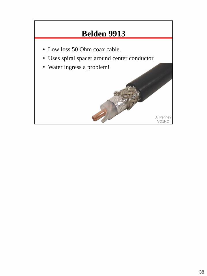
Belden 9913
• Low loss 50 Ohm coax cable.
• Uses spiral spacer around center conductor.
• Water ingress a problem!
38

Hardline Cable
Hard line is used in broadcasting as well as many other forms
of radio communication. It is a coaxial cable constructed using round copper,
silver or gold tubing or a combination of such metals as a shield. Some lower-
quality hard line may use aluminum shielding, aluminum however is easily
oxidized and unlike silver oxide, aluminum oxide drastically loses effective
conductivity. Therefore, all connections must be air and water tight. The
center conductor may consist of solid copper, or copper-plated aluminum.
Since skin effect is an issue with RF, copper plating provides sufficient surface
for an effective conductor. Most varieties of hardline used for external chassis
or when exposed to the elements have a PVC jacket; however, some internal
applications may omit the insulation jacket. Hard line can be very thick, typically at least a half inch or 13 mm and up to several times that, and has low
loss even at high power. These large-scale hard lines are almost always used in the connection between a transmitter on the ground and the antenna or
aerial on a tower.
Hard line may also be known by trademarked names such as Heliax (CommScope), or Cablewave (RFS/Cablewave). Larger varieties of hardline
may have a center conductor that is constructed from either rigid or corrugated
copper tubing. The dielectric in hard line may consist of polyethylene foam, air, or a pressurized gas such as nitrogen or desiccated air (dried air). In gas-

charged lines, hard plastics such as nylon are used as spacers to separate the
inner and outer conductors. The addition of these gases into the dielectric
space reduces moisture contamination, provides a stable dielectric constant, and provides a reduced risk of internal arcing. Gas-filled hardlines are usually
used on high-power RF transmitters such as television or radio broadcasting,
military transmitters, and high-power amateur radio applications but may also
be used on some critical lower-power applications such as those in the microwave bands. However, in the microwave region, waveguide is more
often used than hard line for transmitter-to-antenna, or antenna-to-receiver
applications.
The various shields used in hardline also differ; some forms use rigid tubing, or
pipe, while others may use a corrugated tubing, which makes bending easier,
as well as reduces kinking when the cable is bent to conform. Smaller
varieties of hard line may be used internally in some high-frequency
applications, in particular in equipment within the microwave range, to reduce interference between stages of the device.
39

Al Penney
VO1NO
40

Al Penney
VO1NO
No need for solid center conductors due to skin effect.
Al Penney
VO1NO
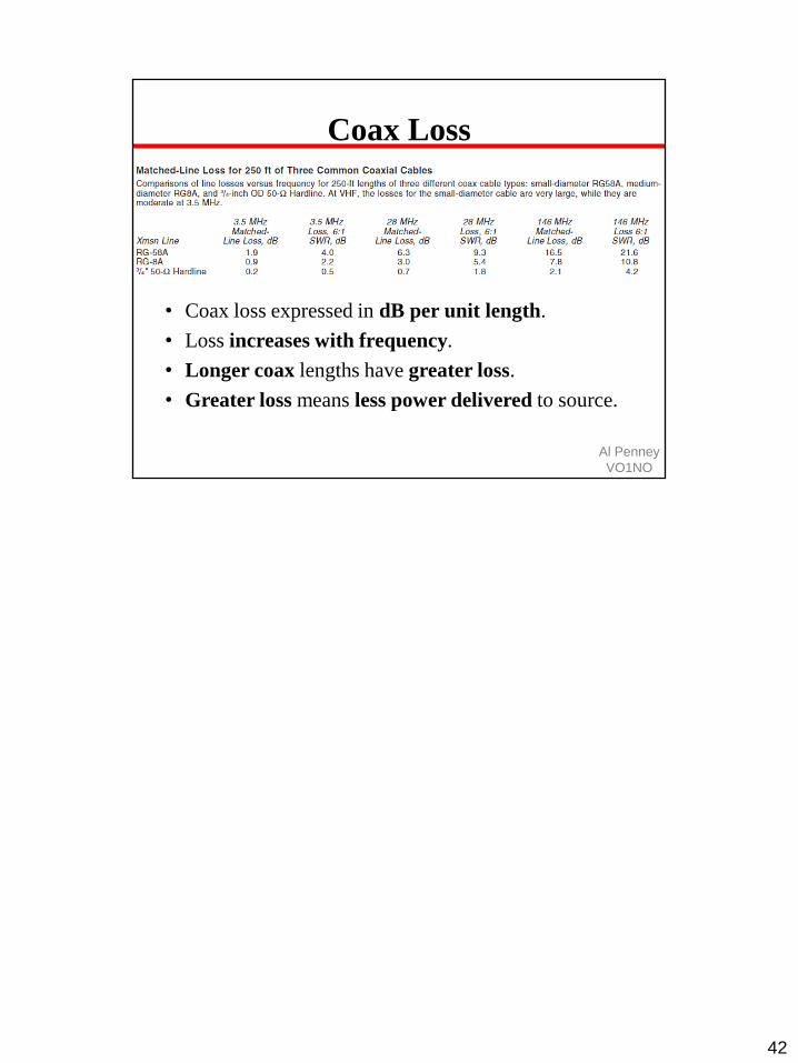
Coax Loss
• Coax loss expressed in dB per unit length.
• Loss increases with frequency.
• Longer coax lengths have greater loss.
• Greater loss means less power delivered to source.
42

Al Penney
VO1NO
43

Al Penney
VO1NO
Note: Coax losses shown above are in dB for 100 feet lengths at specified
frequencies. Loss is a length multiplier, so a 200 ft length would have twice the loss shown above and a 50 ft length would have half the loss.

Coax Connectors
• Enable coax cable to be connected to devices
and antennas.
• Type depends on cable, use and frequency.
• Buy from reputable manufacturers.
• Look for Teflon insulation, silver coating on
parts that must be soldered, and gold plating
on pieces that mate.
Al Penney
VO1NO
45

PL259 and SO239
• Called “UHF” connectors.
• Good on HF, somewhat useful on 2M, not any
higher in frequency however.
• Connects to RG8/U and RG213/U cable.
• PL259 plugs into SO239.
• NOT weatherproof!
Al Penney
VO1NO
The UHF connector is a dated name for a threaded RF connector. The
connector design was invented in the 1930s for use in the radio industry, and is a shielded form of the "banana plug. It is a widely used standard connector
for HF transmission lines on full-sized radio equipment, with BNC connectors
predominating for smaller, hand-held equipment.
The name "UHF" is a source of legitimate confusion, since the name of the
connectors did not change when the frequency ranges were renamed. The
design was named during an era when "UHF" meant frequencies over 30 MHz. Today Ultra high frequency (UHF) instead refers to frequencies
between 300 MHz and 3 GHz and the range of frequencies formerly known
as UHF is now called "VHF". Further adding to the confusion, the so-called
"UHF" connectors are only well suited for the lower-VHF range and lower; they
perform poorly for the higher modern UHF region. A more appropriate name
would be "HF" connectors.
There is no active specification or standard governing the mechanical and
electrical characteristics of the so-called "UHF" connector system making it
effectively a deprecated design.
UHF connectors have a non-constant surge impedance. For this reason, UHF

connectors are generally usable through HF and the lower portion of what is
now known as the VHF frequency range. Despite the name, the UHF
connector is rarely used in commercial applications for today's UHF frequencies, as the non-constant surge impedance creates
measurable electrical signal reflections above 100 MHz.
Better quality UHF connectors can handle RF peak power levels well over one kilowatt based on the voltage rating of 500 Volts peak. In practice, a better
quality UHF connector will handle over 4 kV peak voltage. Manufacturers
typically test UHF jumpers in the 3-5 kV range. UHF connectors are standard
on HF amateur amplifiers rated at 1500+ Watts output.
46

Using PL259 with RG58/U
• An UG175 adaptor is needed to attach a PL259
to RG58/U.
• Get the right one – similar looking adaptors
exist for RG59, but have a different diameter.
Al Penney
VO1NO
47

Al Penney
VO1NO
48

BNC Connectors
• “Bayonet Neill Concelman”
• Quick connect/disconnect.
• Good to 2 GHz or more, but limited in power
handling capability.
• Not weatherproof.
Al Penney
VO1NO
49
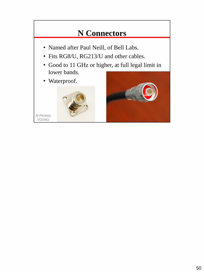
N Connectors
• Named after Paul Neill, of Bell Labs.
• Fits RG8/U, RG213/U and other cables.
• Good to 11 GHz or higher, at full legal limit in
lower bands.
• Waterproof.
Al Penney
VO1NO
50

F Connectors
• Used on RG59 and RG6 for TV applications.
• Some use them for receive antennas.
• Easy to attach, but not very strong or
waterproof.
Al Penney
VO1NO
51

SMA Connectors
• Sub Miniature version A
• Used on Handi-Talkis, WiFi equipment.
• DC to 18 GHz
• 50 Ohms.
Al Penney
VO1NO
SMA (SubMiniature version A) connectors are semi-precision coaxial RF
connectors developed in the 1960s as a minimal connector interface for coaxial
cable with a screw-type coupling mechanism. The connector has a
50 Ω impedance. SMA is designed for use from DC (0 Hz) to 18 GHz, and is
most commonly used in microwave systems, hand-held radio and mobile
telephone antennas, and more recently with WiFi antenna systems and USB software-defined radio dongles. It is also commonly used in radio
astronomy, particularly at higher frequencies (5 GHz+).
SMA connectors must not be confused with the standard household 75-ohm type F coax connector (diameters: Male 7⁄16 inch (11 mm) circular or hex;
female 3⁄8 in (9.5 mm) external threads), as there is only about a 2 mm
difference overall in the specifications. Type F cannot be mated with SMA
connectors without the use of an adapter.

Adaptors
Al Penney
VO1NO
53

Al Penney
VO1NO
54

Al Penney
VO1NO
Always do a continuity check on coax cable after installing connectors (not shown here).

Care of Coax Cable
• Do not kink or bend cable too sharply – the
center conductor can migrate.
• Minimum bend radius is 5-10 times cable
diameter.
• Protect from water ingress!
• Do not drag or step on cable.
Al Penney
VO1NO
56

Drip Loop
Al Penney
VO1NO
57

Al Penney
VO1NO
58

Al Penney
VO1NO
59

Al Penney
VO1NO
60

Coax seal

Al Penney
VO1NO
62

Al Penney
VO1NO
63

Al Penney
VO1NO
64

Al Penney
VO1NO
65

Al Penney
VO1NO
Tape back end of connectors to protect against water ingress and prevent the connector from twisting on the cable.

Al Penney
VO1NO
67

Baluns
• Balanced to Unbalanced
• Enables transition from a balanced feedline to
an unbalanced feedline/antenna and vice versa.
• Can also achieve impedance transformation.
• Can be made with toroid or straight ferrites, air
cores, or coax cable.
• Unun and Balbals are variations.
Al Penney
VO1NO
A balun (portmanteau of "balanced to unbalanced") is an electrical device that
converts between a balanced signal and an unbalanced signal. A balun can
take many forms and may include devices that also transform impedances but
need not do so. Transformer baluns can also be used to connect lines of
differing impedance. Sometimes, in the case of transformer baluns, they use magnetic coupling but need not do so. Common-mode chokes are also
used as baluns and work by eliminating, rather than ignoring, common mode signals.
There are two variations of this device - they are:
•the unun, which transfers signal from one unbalanced line to another.
•the balbal, which transfers signal from one balanced line to another.
A balun is a transformer that matches a balanced load (such as a horizontal dipole or Yagi antenna) to an unbalanced resistive source (such as a transmitter output or a coaxial
feedline).

Why Use Baluns?
• Balanced antenna has equal but opposite currents on center conductor and inside shield.
• Unbalance can result in current flowing on outside of coax shield.
• This causes current imbalance on antenna, changing the transmission pattern of a directional antenna, feedline radiation, etc.
Al Penney
VO1NO
A Balun is used to "balance" unbalanced systems - i.e. those where power flows from
an unbalanced line to a balanced line (hence, balun derives from balance
to unbalanced). As an example, consider a coaxial cable connected to a half-wave
dipole antenna shown above.
In the Figure, a coaxial cable is connected to a dipole antenna. For a dipole antenna to
operate properly, the currents on both arms of the dipole should be equal in magnitude
(I1 equals I2, which should equal I4). When a coaxial cable is connected directly to a
dipole antenna however, the currents will not necessarily be equal. To see this, note
that the current along a transmission line should be of equal magnitude on the inner
and outer conductors, as is typically the case. Observe what happens when the coax is
connected to the dipole. The current on the center conductor (the red/pink center core
of the coax, labeled I1) has no where else to go, so must flow along the dipole arm
that is connected to it. However, the current that travels along the inner side of the
outer conductor (I2) has two options: it can travel down the dipole antenna, or down
the reverse (outer) side of the outer conductor of the coaxial cable (labeled I3 in the
Figure).
Ideally, the current I3 should be zero. In that case, the current along the dipole arm
connected to the outer conductor of the coax will be equal to the current on the other
dipole arm - a desirable antenna characteristic. Because the dipole wants equal or
balanced currents along its arms, it is the balanced section. The coaxial cable does not
necessarily give this however - some of the current may travel down the outside of the

outer coax, leading to unbalanced operation - this is the unbalanced section.
The solution to this problem, however you come up with it, is a balun. A balun forces
an unbalanced transmission line to properly feed a balanced component. In Figure 1,
this would be done by forcing I3 to be zero somehow - this is often called choking the
current or a current choke.
69

Common Mode Choke Balun
• Coil of feedline at feedpoint forms enough
inductance to “choke” off current on outside.
• Can use toroids to increase inductance.
Al Penney
VO1NO
Placing a “common-mode choke” whose reactance is + j1000 ohms at the antenna’s
feed point removes virtually all trace current on the outside of the braid. This is
always true for the simple case where the feedline was dressed symmetrically, directly
down under the feed point. Certain slanted-feedline lengths required additional
common-mode chokes, placed at l/4 intervals down the transmission line from the
feed point.
The simplest method to create a common-mode choke balun with coaxial cable is to
wind up some of it into a coil at the feed point of the antenna. The normal
transmission-line currents inside the coax are
unaffected by the coiled configuration, but commonmode currents trying to flow on
the outside of the coax braid are “choked off” by the reactance of the coil. This coax-
coil choke could also be referred to
as an “air-wound” choke, since no ferrite-core material is used to help boost the
common-mode reactance at low frequencies.
A coax choke can be made like a flat coil— that is, like a coil of rope whose adjacent
turns are carefully placed side-by-side to reduce inter-turn distributed capacity, rather
than in a
“scramble-wound” fashion. Sometimes a coil form made of PVC is used to keep
things orderly.
This type of choke shows a broad resonance due to its inductance and distributed

capacity that can easily cover three amateur bands. See Fig 30. Some geometries are
reasonably effective
over the entire HF range. If particular problems are encountered on a single band, a
coil that is resonant at that band may be added. The coils shown in Table 3 were
designed to have a high
impedance at the indicated frequencies, as measured with an impedance meter. Many
other geometries can also be effective. This construction technique is not effective
with twin-lead because of excessive coupling between adjacent turns.
This choke-type of balan is sometimes referred to as a “current balun” since it has the
hybrid properties of a tightly coupled transmission-line transformer (with a 1:1
transformation ratio) and a coil. The transmission- line transformer forces the current
at the output terminals to be equal, and the coil portion chokes off common-mode
currents.
70

Choke Baluns
Al Penney
VO1NO
71

Ferrite Bead Choke
Ferrite beads are used for RF decoupling and parasitic suppression. When
placed over a wire, cable or coaxial cable they suppresses common mode
current flowing on the wire or wire bundle or the outside of the coax shield but
does not affect the signal inside the coax cable or wire (differential current).

Transformer Baluns
• Two or more windings on an air or ferrite core.
• Can provide a broadband match between
transmission line and antenna.
• In addition to converting balanced to
unbalanced they can provide 1:1, 4:1 and many
other impedance shifts.
• Also provide electrical isolation.
Al Penney
VO1NO
Toroid Impedance Matching Transformers
The toroidal transformer is capable of providing a broadband match between antenna and transmission line, or between transmission line and transmitter or receiver. Many other matching methods are frequency sensitive and must be readjusted whenever the operating frequency is changed by even a small percentage. Although
this problem is of no great concern to fixed frequency radio stations, it is of critical importance to stations that operate on a variety of frequencies or widely separated
bands of frequencies.
In classical transformers, there are two electrically separate windings of wire coils around the transformer's core. The advantage of transformer-type
over other types of balun is that the electrically separate windings for input and
output allow these baluns to connect circuits whose ground-level voltages are subject to ground loops or are otherwise electrically incompatible; for that
reason they are often called isolation transformers.
This type is sometimes called a voltage balun. The primary winding receives
the input signal, and the secondary winding puts out the converted signal. The
core that they are wound on may either be empty (air core) or, equivalently, a

magnetically neutral material like a porcelain support, or it may be a material which is good magnetic conductor like ferrite in modern high-frequency (HF)
baluns, or soft iron as in the early days of telegraphy.
The electrical signal in the primary coil is converted into a magnetic field in the
transformer's core. When the electrical current through the primary reverses, it
causes the established magnetic field to collapse. The collapsing magnetic
field then induces an electric field in the secondary winding.
The ratio of loops in each winding and the efficiency of the coils' magnetic coupling determines the ratio of electrical potential (voltage) to electrical
current and the total power of the output. For idealized transformers, although
the ratio of voltage to current will change in exact proportion to the square of
the winding ratio, the power (measured in watts) remains identical. In real
transformers, some energy is lost inside to heating of the metallic core of the
transformer, and lost outside to the surrounding environment because of
imperfect magnetic coupling between the two coils.
73
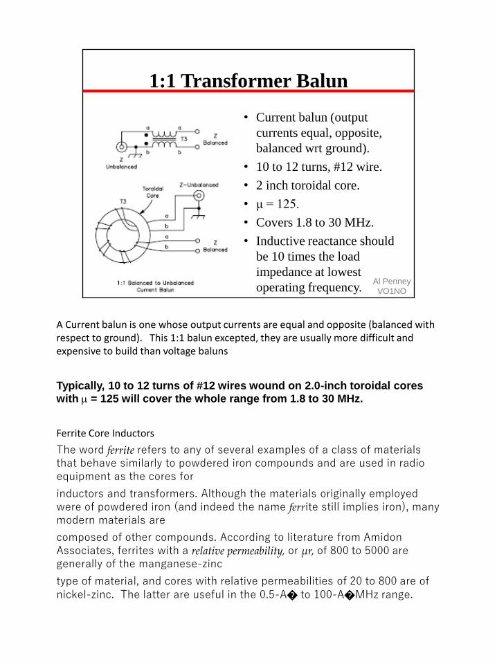
1:1 Transformer Balun
• Current balun (output
currents equal, opposite,
balanced wrt ground).
• 10 to 12 turns, #12 wire.
• 2 inch toroidal core.
• μ = 125.
• Covers 1.8 to 30 MHz.
• Inductive reactance should
be 10 times the load
impedance at lowest
operating frequency.Al Penney
VO1NO
A Current balun is one whose output currents are equal and opposite (balanced with respect to ground). This 1:1 balun excepted, they are usually more difficult and expensive to build than voltage baluns
Typically, 10 to 12 turns of #12 wires wound on 2.0-inch toroidal cores
with m = 125 will cover the whole range from 1.8 to 30 MHz.
Ferrite Core Inductors
The word ferrite refers to any of several examples of a class of materials that behave similarly to powdered iron compounds and are used in radio equipment as the cores for
inductors and transformers. Although the materials originally employed were of powdered iron (and indeed the name ferrite still implies iron), many modern materials are
composed of other compounds. According to literature from Amidon Associates, ferrites with a relative permeability, or μr, of 800 to 5000 are generally of the manganese-zinc
type of material, and cores with relative permeabilities of 20 to 800 are of nickel-zinc. The latter are useful in the 0.5-A� to 100-A�MHz range.

Al Penney
VO1NO
75

1:1 Transformer Balun
• Voltage Balun (output
voltages equal, opposite,
balanced wrt ground).
• Three windings connected in
series.
• Can be air, toroidal or ferrite
bar core.
Al Penney
VO1NO
A Voltage balun is one whose output voltages are equal and opposite (balanced with respect to ground).

Al Penney
VO1NO
77

Al Penney
VO1NO
78

4:1 Transformer Balun
• Voltage balun.
• 4:1 impedance transformation.
• 200 to 50 ohms.
• Can also be air core.
Al Penney
VO1NO
A Voltage balun is one whose output voltages are equal and opposite (balanced with respect to ground).

Al Penney
VO1NO
80

1:1 Transmission Line Balun
• Known as a Folded Balun.
• Quarter wave section of
cable attached to center
conductor and braid at
bottom.
• NOTE: Do NOT use VF to
calculate length.
Al Penney
VO1NO
Folded Balun
aka Pawsey Stub and 1/4 Wave Coaxial BalunFigure shows the idea behind the Pawsey stub which is known in Electrical Engineering circles as a variant of the Folded Balun. While the Gray conductor in the Figure only needs to be a wire of similar size to the coaxial cable feedline, it is often made from a scrap piece of the same cable. Each end of the outer shield of the stub is connected to the feed system. A common thought of many is since this is coaxial cable, we need velocity factor adjustments. Since the electric and magnetic fields (of the stub system) are in air, I think velocity factor does not apply.

4:1 Transmission Line Balun
• Voltage Balun.
• Uses half wavelength section of
coaxial cable (factor in the VF).
• Suitable for one band only.
• Often used on VHF/UHF Yagis.
• 75 ohm cable gives 300 ohms.
Al Penney
VO1NO
82

Al Penney
VO1NO
83

Voltage Standing Wave Ratio
• Abbreviated VSWR, or more commonly SWR.
• Measure of the effectiveness of the coupling
between two transmission lines or between a
transmission line and the source or load.
• If impedances not matched, some energy will be
reflected back, setting up a standing wave in the
transmission line.
• VSWR = Vmax / Vmin
• Expressed as a ratio: 1:1 is perfect, 2:1 acceptable,
5:1 generally too high.Al Penney
VO1NO
VSWR Definition
Voltage standing wave ratio (VSWR) is defined as the ratio between
transmitted and reflected voltage standing waves in a radio frequency (RF)
electrical transmission system. It is a measure of how efficiently RF power is
transmitted from the power source, through a transmission line, and into theload. A common example is a power amplifier connected to an antenna
through a transmission line.
SWR is, thus, the ratio between transmitted and reflected waves. A high SWR
indicates poor transmission-line efficiency and reflected energy, which can
damage the transmitter and decrease transmitter efficiency. Since SWR
commonly refers to the voltage ratio, it is usually known as voltage standing
wave ratio (VSWR).
VSWR and System Efficiency
In an ideal system, 100% of energy is transmitted from the power stages to the
load. This requires an exact match between the source impedance (the
characteristic impedance of the transmission line and all its connectors), and
the load impedance. The signal's AC voltage will be the same from end to end
since it passes through without interference.
In a real system, mismatched impedances cause some of the power to bereflected back toward the source (like an echo). These reflections cause

constructive and destructive interference, leading to peaks and valleys in the
voltage, varying with time and distance along the transmission line. VSWR
quantifies these voltage variances, hence another commonly used definition
for Voltage Standing Wave Ratio is that it is the ratio of the highest voltage to
the lowest voltage, at any point on the transmission line.
For an ideal system, voltage does not vary. Therefore, its VSWR is 1.0 (or
more usually expressed as a ratio of 1:1). When reflections occur, voltages
vary and VSWR is higher, for example 1.2 (or 1.2: 1). Increased VSWR
correlates with reduced transmission line (and therefore overall transmitter)
efficiency.
For a radio (transmitter or receiver) to deliver power to an antenna, the
impedance of the radio and transmission line must be well matched to the antenna's impedance. The parameter VSWR is a measure that
numerically describes how well the antenna is impedance matched to the radio
or transmission line it is connected to.
VSWR stands for Voltage Standing Wave Ratio, and is also referred to as Standing
Wave Ratio (SWR). VSWR is a function of the reflection coefficient, which describes
the power reflected from the antenna.
The VSWR is always a real and positive number for antennas. The smaller the VSWR
is, the better the antenna is matched to the transmission line and the more power is
delivered to the antenna. The minimum VSWR is 1:1 (“one to one”). In this case, no
power is reflected from the antenna, which is ideal.
In radio engineering and telecommunications, standing wave ratio (SWR) is a
measure of impedance matching of loads to the characteristic impedance of
a transmission line or waveguide. Impedance mismatches result in standing
waves along the transmission line, and SWR is defined as the ratio of the
partial standing wave’s amplitude at an antinode (maximum) to the amplitude
at a node (minimum) along the line.
The SWR is usually thought of in terms of the maximum and minimum AC voltages along the transmission line, thus called the voltage standing
wave ratio or VSWR (sometimes pronounced "vizwar". For example, the
VSWR value 1.2:1 denotes an AC voltage due to standing waves along the
transmission line reaching a peak value 1.2 times that of the minimum AC
voltage along that line. The SWR can as well be defined as the ratio of the
maximum amplitude to minimum amplitude of the transmission line's currents, electric field strength, or the magnetic field strength. Neglecting
transmission line loss, these ratios are identical.
84

Voltage Standing Wave Ratio
VSWR = Vmax / Vmin = 1.6 volts / 0.4 volts = 4
Therefore, VSWR = 4:1Al Penney
VO1NO
Standing waves on a transmission line, with the resulting voltages (VNET)
shown in different colors during one complete cycle of the applied voltage. The
generated wave with an amplitude of 1 travels from left to right and is partially reflected by the load at right. SWR = VMAX / VMIN = 1.6 / 0.4 = 4.0. (Graphic
created by Wikipedia contributor, Interferometrist and is used under the
Creative Commons Attribution-Share Alike 4.0 International license.)
VSWR is determined from the voltage measured along a transmission line leading to
an antenna. VSWR is the ratio of the peak amplitude of a standing wave to the
minimum amplitude of a standing wave, as seen in the following Figure:
When an antenna is not matched to the receiver, power is reflected. This causes a
"reflected voltage wave", which creates standing waves along the transmission line.
The result are the peaks and valleys as seen in Figure 1. If the VSWR = 1:1, there
would be no reflected power and the voltage would have a constant magnitude along
the transmission line.

VSWR
VSWR = 4:1
VSWR = 2:1
VSWR = 9:1
Al Penney
VO1NO
Standing waves on transmission line, net voltage shown in different colors
during one period of oscillation. Incoming wave from left (amplitude = 1) is
partially reflected with (top to bottom) Γ = 0.6, −0.333, and 0.8 ∠60°. Resulting SWR = 4, 2, 9.

Al Penney
VO1NO
Incident wave (blue) is fully reflected (red wave) out of phase
at short-circuited end of transmission line, creating a net
voltage (black) standing wave where the SWR = ∞.
Voltage Standing Wave Ratio
Impedance matching
SWR is used as a measure of impedance matching of a load to
the characteristic impedance of a transmission line carrying radio
frequency (RF) signals. This especially applies to transmission lines
connecting radio transmitters and receivers with their antennas, as well as
similar uses of RF cables such as cable television connections to TV receivers
and distribution amplifiers. Impedance matching is achieved when the source
impedance is the complex conjugate of the load impedance. The easiest way
of achieving this, and the way that minimizes losses along the transmission line, is for the imaginary part of the complex impedance of both the source and
load to be zero, that is, pure resistances, equal to the characteristic impedance
of the transmission line. When there is a mismatch between the load
impedance and the transmission line, part of the forward wave sent toward the
load is reflected back along the transmission line towards the source. The
source then sees a different impedance than it expects which can lead to
lesser (or in some cases, more) power being supplied by it, the result being very sensitive to the electrical length of the transmission line.
Such a mismatch is usually undesired and results in standing waves along the
transmission line which magnifies transmission line losses (significant at higher
frequencies and for longer cables). The SWR is a measure of the depth of those standing waves and is, therefore, a measure of the matching of the load

to the transmission line. A matched load would result in an SWR of 1:1
implying no reflected wave. An infinite SWR represents complete reflection by
a load unable to absorb electrical power, with all the incident power reflected
back towards the source.
It should be understood that the match of a load to the transmission line is different from the match of a source to the transmission line or the match of a
source to the load seen through the transmission line. For instance, if there is a
perfect match between the load impedance Zload and the source
impedance Zsource=Z*load, that perfect match will remain if the source and load
are connected through a transmission line with an electrical length of one half
wavelength (or a multiple of one half wavelengths) using a transmission line of any characteristic impedance Z0. However the SWR will generally not be
1:1, depending only on Zload and Z0. With a different length of transmission line,
the source will see a different impedance than Zload which may or may not be a
good match to the source. Sometimes this is deliberate, as when a quarter-
wave matching section is used to improve the match between an otherwise
mismatched source and load.
However typical RF sources such as transmitters and signal generators are
designed to look into a purely resistive load impedance such as 50Ω or 75Ω,
corresponding to common transmission lines' characteristic impedances. In
those cases, matching the load to the transmission line, Zload=Z0, always ensures that the source will see the same load
impedance as if the transmission line weren't there. This is identical to a 1:1 SWR. This condition ( Zload=Z0) also means that the load seen by the source is
independent of the transmission line's electrical length. Since the electrical
length of a physical segment of transmission line depends on the signal
frequency, violation of this condition means that the impedance seen by the
source through the transmission line becomes a function of frequency (especially if the line is long), even if Zload is frequency-independent. So in
practice, a good SWR (near 1:1) implies a transmitter's output seeing the
exact impedance it expects for optimum and safe operation.
87

SWR Meter
• SWR meter compares forward voltage Vf and
reverse voltage Vr on the transmission line
(which are not the same as Vmax and Vmin).
• SWR = Vf + Vr / Vf – Vr
Al Penney
VO1NO
A directional SWR meter measures the magnitude of the forward and reflected waves by sensing each one individually, with directional couplers. A
calculation then produces the SWR.

VSWR Measurements
VSWR = (1+0) / (1-0) = 1:1
VSWR = (1+0.2) / (1-0.2) = 1.5:1
http://www.takuichi.net/hobby/edu/em/standing/onedim/index.html

VSWR Measurements
VSWR = (1+1) / (1-1) = ∞
VSWR = (1+0.5) / (1-0.5) = 3:1
http://www.takuichi.net/hobby/edu/em/standing/onedim/index.html

Al Penney
VO1NO
Power SWR meter, using crossed needles.
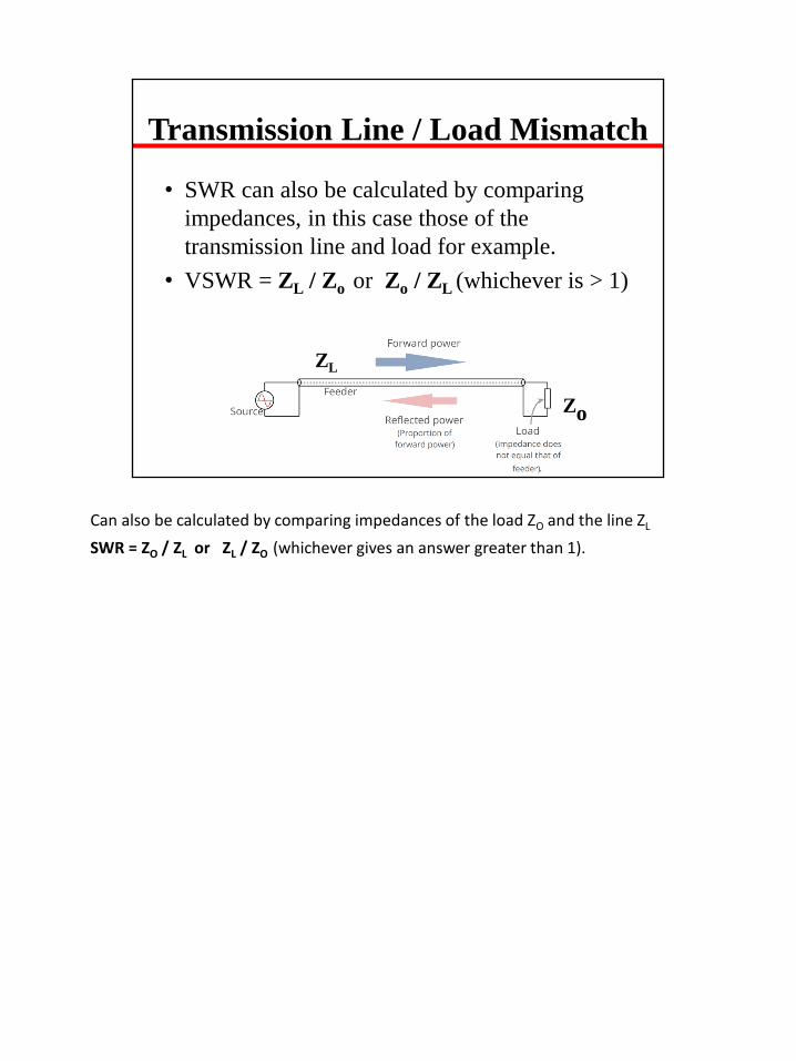
Transmission Line / Load Mismatch
• SWR can also be calculated by comparing
impedances, in this case those of the
transmission line and load for example.
• VSWR = ZL / Zo or Zo / ZL (whichever is > 1)
Zo
ZL
Can also be calculated by comparing impedances of the load ZO and the line ZL
SWR = ZO / ZL or ZL / ZO (whichever gives an answer greater than 1).

Line / Load Mismatch Example
• Driven Element on a 2M Yagi has impedance
of 200 Ohms. What is SWR if fed with 50
Ohm coax cable?
93

Line / Load Mismatch Example
• Driven Element on a 2M Yagi has impedance of 200 Ohms. What is SWR if fed with 50 Ohm coax cable?
• VSWR = ZL / Zo or Zo / ZL (whichever is > 1)
• VSWR = ZL / Zo = 200/50 = 4:1
• Question – How could we feed this antenna with 50 Ohm coax cable and have an acceptable SWR?
94

With a 4:1 Coax Balun Of Course!
95

Impact of SWR
• High SWR may cause the transmitter to load
incorrectly.
• It may cause high voltages to exist in the
transmitter, damaging components.
• Modern solid state radios have SWR sensing
circuits that fold power back when high SWR
exists.
Al Penney
VO1NO
Practical implications of SWR
The most common case for measuring and examining SWR is when installing and tuning transmitting antennas. When a transmitter is connected to an
antenna by a feed line, the driving point impedance of the antenna must match
the characteristic impedance of the feed line in order for the transmitter to see
the impedance it was designed for (the impedance of the feed line, usually 50
or 75 ohms).
The impedance of a particular antenna design can vary due to a number of
factors that cannot always be clearly identified. This includes the transmitter frequency (as compared to the antenna's design or resonant frequency), the
antenna's height above and quality of the ground, proximity to large metal
structures, and variations in the exact size of the conductors used to construct
the antenna.
When an antenna and feed line do not have matching impedances, the
transmitter sees an unexpected impedance, where it might not be able to
produce its full power, and can even damage the transmitter in some cases. The reflected power in the transmission line increases the average
current and therefore losses in the transmission line compared to power actually delivered to the load. It is the interaction of these reflected waves with
forward waves which causes standing wave patterns, with the negative
repercussions we have noted.

Impact of SWR
• High SWR also causes additional losses in
the transmission line.
• These losses are caused by dielectric and
conductor heat losses.
• This means less power gets to antenna.
• In some cases, high SWR can cause the coax
to get hot, especially with lossy coax.
Al Penney
VO1NO
Matching the impedance of the antenna to the impedance of the feed line can
sometimes be accomplished through adjusting the antenna itself, but otherwise is possible using an antenna tuner, an impedance matching device.
Installing the tuner between the feed line and the antenna allows for the feed
line to see a load close to its characteristic impedance, while sending most of
the transmitter's power (a small amount may be dissipated within the tuner) to
be radiated by the antenna despite its otherwise unacceptable feed point
impedance. Installing a tuner in between the transmitter and the feed line can
also transform the impedance seen at the transmitter end of the feed line to
one preferred by the transmitter. However, in the latter case, the feed line still
has a high SWR present, with the resulting increased feed line losses
unmitigated.
The magnitude of those losses are dependent on the type of transmission line,
and its length. They always increase with frequency. For example, a certain
antenna used well away from its resonant frequency may have an SWR of 6:1. For a frequency of 3.5 MHz, with that antenna fed through 75 meters of RG-8A
coax, the loss due to standing waves would be 2.2 dB. However the same 6:1
mismatch through 75 meters of RG-8A coax would incur 10.8 dB of loss at
146 MHz. Thus, a better match of the antenna to the feed line, that is, a lower
SWR, becomes increasingly important with increasing frequency, even if the transmitter is able to accommodate the impedance seen (or an antenna tuner

is used between the transmitter and feed line).
Certain types of transmissions can suffer other negative effects from reflected
waves on a transmission line. Analog TV can experience "ghosts" from
delayed signals bouncing back and forth on a long line. FM stereo can also be
affected and digital signals can experience delayed pulses leading to bit errors.
Whenever the delay times for a signal going back down and then again up the
line are comparable to the modulation time constants, effects occur. For this
reason, these types of transmissions require a low SWR on the feedline, even
if SWR induced loss might be acceptable and matching is done at the
transmitter.
97

Al Penney
VO1NO
ADDITIONAL POWER LOSS DUE TO SWR
The power lost in a given line is least when the line is terminated in a resistance equal
to its characteristic impedance, and as stated previously, that is called the matched-line
loss. There is however an additional loss that increases with an increase in the SWR.
This is because the effective values of both current and voltage become greater on
lines with standing waves. The increase in effective current raises the ohmic losses
(I2R) in the conductors, and the increase in effective voltage increases the losses in
the dielectric (E2/R).
The increased loss caused by an SWR greater than 1:1 may or may not be serious. If
the SWR at the load is not greater than 2:1, the additional loss caused by the standing
waves, as compared with the loss when the line is perfectly matched, does not amount
to more than about 1/2 dB, even on very long lines. One-half dB is an undetectable
change in signal strength. Therefore, it can be said that, from a practical standpoint in
the HF bands, an SWR of 2:1 or less is every bit as good as a perfect match, so far as
additional losses due to SWR are concerned.
However, above 30 MHz, in the VHF and especially the UHF range, where low
receiver noise figures are essential for effective weak-signal work, matched-line losses
for commonly available types of coax can
be relatively high. This means that even a slight mismatch may become a concern
regarding overall transmission line losses. At UHF one-half dB of additional loss may

be considered intolerable!
98

Impact of SWR
In an ideal system, all the RF power is transmitted through based on an exact
match of impedances from the transmitter to the cable and antenna. The signal’s AC voltage sees no interference and no power is reflected. Real life
systems have unexpected impedances from simple items like connectors or
bigger issues like a damaged antenna which cause power to be reflected.
VSWR is a ratio calculated based on the forward and reflected power, with the
ideal system having a VSWR of 1.0 (or 1:1).
VSWR can have a significant impact on through power and continuous
monitoring allows trends to be seen. As shown on this graph for example,
monitoring may allow you to identify when VSWR climbs to just 2.0 which
means 89% of power is still getting through and users may not yet be
significantly impacted. Without VSWR monitoring, the first time you hear of the
problem may be from users when VSWR has reached 4.5 with only 59% of
power getting through.

Matching the Xmitter to the Feedline
• Modern radios use broadband finals designed
to operate into 50 ohms.
• Most will reduce power once SWR is 2:1 or
greater.
• Older tube radios were more forgiving – not so
with modern radios!
• High SWR means voltages and currents that
can destroy solid state finals.
Al Penney
VO1NO
Modern amateur transceivers use broadband, untuned solid-state final amplifiers,
designed to operate into 50 ohms. Such a transmitter is able to deliver its rated output
power—at its rated level of distortion—only when it is operated into the load for
which it was designed. An SSB transmitter that is “splattering” is often being driven
hard into the wrong load impedance.
Further, modern radios often employ protection circuitry to reduce output power
automatically if the SWR rises to more than about 2:1. Protective circuits are needed
because solid-state devices can
almost instantly destroy themselves trying to deliver power into the wrong load
impedance. Modern solid-state transceivers often include built-in antenna tuners
(often at extra cost) to match impedances
when the SWR isn’t 1:1. Older vacuum-tube amplifiers were a lot more forgiving
than solid-state devices—they could survive momentary overloads without being
instantly destroyed. The pi-networks used to tune and load old-fashioned vacuum-tube
amplifiers were able to match a fairly wide range of impedances.

Transmitter Matching
• If impedance of feedline at xmitter differs from 50 ohms then mismatch occurs.
• Large mismatch will create high RF voltages in xmitter, possibly causing damage.
• A Transmatch (Antenna Tuner) will “hide” mismatch from the xmitter, allowing it to transmit without danger.
• Mismatch still exists on feedline!
Al Penney
VO1NO
MATCHING THE LINE TO THE TRANSMITTER
The impedance at the input of a transmission line is uniquely determined by a number
of factors: the frequency, the characteristic impedance Z0 of the line, the physical
length,
velocity factor and the matched-line loss of the line, plus the impedance of the
load (the antenna) at the output end of the line. If the impedance at the input of the
transmission line connected to the transmitter differs appreciably from the load
resistance into which the transmitter output circuit is designed to operate, an
impedance-matching network must be inserted between the transmitter and the line
input terminals.
In older ARRL publications, such an impedance-matching network was often called a
Transmatch. This is a coined word, referring to a “Transmitter Matching” network.
Nowadays, radio amateurs commonly
call such a device an antenna tuner.
The function of an antenna tuner is to transform the impedance at the input end of the
transmission line—whatever it may be—to the 50 ohms needed to keep the transmitter
loaded properly. An antenna
tuner does not alter the SWR on the transmission line going to the antenna. It only
ensures that the transmitter sees the 50-ohm load for which it was designed.

http://www.arrl.org/files/file/Technology/tis/info/pdf/9401070.pdf
101

Antenna Tuner
• Despite name, it does not tune the antenna.
• Network of capacitors and inductors that
eliminate inductive or capacitive reactance,
and transform the resistance to 50 ohms.
• Despite common belief, an antenna tuner does
not provide much harmonic attenuation in most
cases.
Al Penney
VO1NO
What an "antenna tuner" actually tunes
Despite its name, an antenna "tuner" does not actually tune the antenna. It
matches the complex impedance of the transmitter to that of the input end of
the feedline. The input impedance of the transmission line will be different than the characteristic impedance of the feedline if the impedance of the antenna on
the other end of the line does not match the line's characteristic impedance.
The consequence of the mismatch is standing waves on the feedline that alter
the line's impedance at every point along the line.
If both the tuner and the feedline were lossless, tuning at the transmitter end
would indeed produce a perfect match at every point in the transmitter-feedline-antenna system. However, in practical systems lossy feedlines limit
the ability of the antenna tuner to change the antenna's resonant frequency. If
the loss of power is low in the line carrying the transmitter's signal to the
antenna, a tuner at the transmitter end can produce a worthwhile degree of matching and tuning for the antenna and feedline network as a whole. But
with lossy, low-impedance feedlines like the commonly used 50 Ohm coaxial
cable, maximum power transfer only occurs if matching is done at the antenna
in conjunction with a matched transmitter and feedline, producing a match at
both ends of the line.
In any case, regardless of its placement, an ATU does not alter the gain,
efficiency, or directivity of the antenna, nor does it change the internal complex

impedance of the antenna itself.
Efficiency and SWR
If there is still a high standing wave ratio (SWR) in the feedline beyond the
ATU, any loss in that part of the feedline is typically increased by the
transmitted waves reflecting back and forth between the tuner and the
antenna, causing resistive losses in the wires and possibly the insulation of the transmission line. Even with a matching unit at both ends of the feedline – the
near ATU matching the transmitter to the feedline and the remote ATU matching the feedline to the antenna – losses in the circuitry of the two ATUs
will slightly reduce power delivered to the antenna.
Hence, operating an antenna far from its design frequency and compensating
with an ATU between the transmitter and the feedline is not as efficient as using a resonant antenna with a matched-impedance feedline, nor as efficient
as a matched feedline from the transmitter to a remote antenna tuner attached
directly to the antenna.
Harmonic Attenuation in an Antenna Tuner
One potentially desirable characteristic of an antenna tuner is the degree of extra
harmonic attenuation it can provide. While this is desirable in
theory, it is not always achieved in practice. For example, if an antenna tuner is used
with a single, fixed-length antenna on multiple bands, the impedances presented to the
tuner at the fundamental
frequency and at the harmonics will often be radically different, thus attenuating
harmonics. There are some situations in Amateur Radio where the impedance at the
second harmonic is essentially the same as that for the fundamental however,
providing little attenuation to harmonics. This often involves “trapped” antenna
systems or wideband log-periodic designs. For example, a system used by many
amateurs is a “tribander” Yagi that works on 20, 15 and 10 meters. The second
harmonic of a 20-meter transmitter feeding such a tribander can be objectionably
strong for nearby amateurs operating on 10 meters. This is despite the approximately
60 dB of attenuation of the second harmonic provided by the low-pass filters built into
modern solid state transceivers. A linear amplifier can exacerbate the problem, since
its second harmonic may be suppressed only about 46 dB by the typical pi-network
output circuit used in most amplifiers. Even in a trapped antenna system, most
amateur antenna tuners will not attenuate the 10-meter harmonic much at all,
especially if the tuner uses a high-pass T-network. This is the most common network
used commercially because of the wide range of impedances it will match. Some T-
network designs have attempted to improve the harmonic attenuation using parallel
inductors and capacitors instead of a single inductor for the center part of the T.
102

Unfortunately, this often leads to more loss and more critical tuning at the
fundamental, while providing little, if any, additional harmonic suppression in actual
installations.
Harmonics and Pi-Network Tuners
In a trapped antenna system, if a different network is used for an antenna tuner (such
as a lowpass Pi network), there will be additional attenuation of harmonics, perhaps as
much as 30 dB for a
loaded Q of 3. The exact degree of harmonic attenuation, however, is often limited
due to the stray inductance and capacity present in most tuners at harmonic
frequencies. Further, the matching range
for a Pi-network tuner is fairly limited because of the range of input and output
capacitance needed for widely varying loads.
Harmonics and Stubs
Far more reliable suppression of harmonics can be achieved using shorted quarter-
wave transmission- line stubs at the transmitter output. A typical 20-meter l/4
wavelength shorted stub (which looks like an open circuit at 20 meters, but a short
circuit at 10 meters) will provide about 25 dB of attenuation to the second harmonic.
It will handle full legal amateur power too. In short, an antenna tuner that is capable
of matching a wide range of impedances should not be relied on to give additional
harmonic suppression.
102

Influence of Transmission Line
• If the impedance terminating a transmission line differs significantly from the characteristic impedance of the line, then the impedance at input will depend on the lengthof the transmission line.
• Some antenna tuners may not be able to match some impedances, so changing length of transmission line may help.
• Note that the SWR will not change.
If the line impedance and load impedance don’t match, the input will see an impedance value that is a function of the line length. The mathematics to calculate the value of the impedance in this situation is more than a little demanding and then some!
Designers can take advantage of this characteristic by using special lengths of transmission lines of certain impedances to match some types of antennas to 50 Ohm impedance coaxial cable. This topic is beyond what you need to know for the Basic course however!

Al Penney
VO1NO
Common Antenna Tuner Circuit
104

Al Penney
VO1NO
The result of trying to tune an antenna tuner with too much power initially!
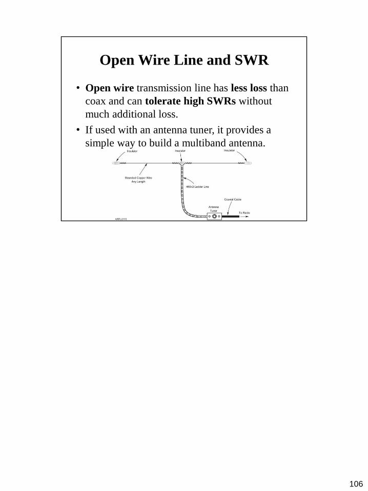
Open Wire Line and SWR
• Open wire transmission line has less loss than
coax and can tolerate high SWRs without
much additional loss.
• If used with an antenna tuner, it provides a
simple way to build a multiband antenna.
106

Questions?
Al Penney
VO1NO
107

The characteristic impedance of a transmission line is determined by the:
• frequency at which the line is operated
• load placed on the line
• physical dimensions and relative positions of the conductors
• length of the line
Review Question 1
Al Penney
VO1NO
108

The characteristic impedance of a transmission line is determined by the:
• frequency at which the line is operated
• load placed on the line
• physical dimensions and relative positions of the conductors
• length of the line
< physical dimensions and relative positions of the conductors >
Review Question 1
Al Penney
VO1NO
109

The characteristic impedance of a 20 metre piece of transmission line is 52 ohms. If 10 metres were cut off, the impedance would be:
• 13 ohms
• 52 ohms
• 26 ohms
• 39 ohms
Review Question 2
Al Penney
VO1NO
110

The characteristic impedance of a 20 metre piece of transmission line is 52 ohms. If 10 metres were cut off, the impedance would be:
• 13 ohms
• 52 ohms
• 26 ohms
• 39 ohms
< 52 ohms >
Review Question 2
Al Penney
VO1NO
111

What commonly available antenna transmission line can be buried directly in the ground for some distance without adverse effects?
• 75 ohm twin-lead
• Coaxial cable
• 300 ohm twin-lead
• 600 ohm open-wire
Review Question 3
Al Penney
VO1NO
112

What commonly available antenna transmission line can be buried directly in the ground for some distance without adverse effects?
• 75 ohm twin-lead
• Coaxial cable
• 300 ohm twin-lead
• 600 ohm open-wire
< Coaxial cable >
Review Question 3
Al Penney
VO1NO
113

The characteristic impedance of a transmission line is:
• equal to the pure resistance which, if connected to the end of the line, will absorb all the power arriving along it
• the impedance of a section of the line one wavelength long
• the dynamic impedance of the line at the operating frequency
• the ratio of the power supplied to the line to the power delivered to the load
Review Question 4
Al Penney
VO1NO
114

The characteristic impedance of a transmission line is:
• equal to the pure resistance which, if connected to the end of the line, will absorb all the power arriving along it
• the impedance of a section of the line one wavelength long
• the dynamic impedance of the line at the operating frequency
• the ratio of the power supplied to the line to the power delivered to the load
< equal to the pure resistance which, if connected to the end of the line, will absorb all the power arriving along it >
Review Question 4
Al Penney
VO1NO
115

A transmission line differs from an ordinary circuit or network in communications or signaling devices in one very important way. That important aspect is:
• capacitive reactance
• inductive reactance
• resistance
• propagation delay
Review Question 5
Al Penney
VO1NO
116

A transmission line differs from an ordinary circuit or network in communications or signaling devices in one very important way. That important aspect is:
• capacitive reactance
• inductive reactance
• resistance
• propagation delay
< propagation delay >
Review Question 5
Al Penney
VO1NO
117

If the impedance terminating a transmission line differs significantly from the characteristic impedance of the line, what will be observed at the input of the line?
• An impedance nearly equal to the characteristic impedance
• Some value of impedance influenced by line length
• An infinite impedance
• A negative impedance
Review Question 6
Al Penney
VO1NO
118

If the impedance terminating a transmission line differs significantly from the characteristic impedance of the line, what will be observed at the input of the line?
• An impedance nearly equal to the characteristic impedance
• Some value of impedance influenced by line length
• An infinite impedance
• A negative impedance
< Some value of impedance influenced by line length >
If the line impedance and load impedance don’t match, the input will see an impedance value that is a function of the line length. The mathematics to calculate the value of the impedance in this situation is more than a little demanding and then some!
Review Question 6
Al Penney
VO1NO
119
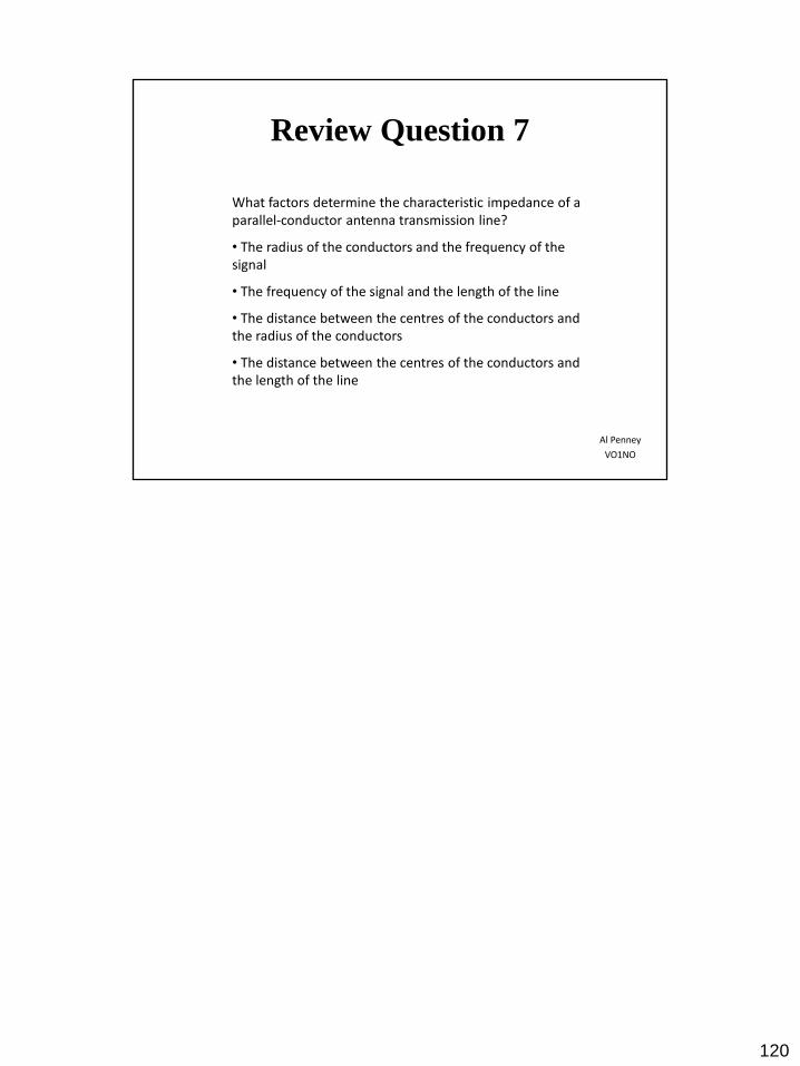
What factors determine the characteristic impedance of a parallel-conductor antenna transmission line?
• The radius of the conductors and the frequency of the signal
• The frequency of the signal and the length of the line
• The distance between the centres of the conductors and the radius of the conductors
• The distance between the centres of the conductors and the length of the line
Review Question 7
Al Penney
VO1NO
120

What factors determine the characteristic impedance of a parallel-conductor antenna transmission line?
• The radius of the conductors and the frequency of the signal
• The frequency of the signal and the length of the line
• The distance between the centres of the conductors and the radius of the conductors
• The distance between the centres of the conductors and the length of the line
< The distance between the centres of the conductors and the radius of the conductors >
Review Question 7
Al Penney
VO1NO
121

What factors determine the characteristic impedance of a coaxial antenna transmission line?
• The ratio of the diameter of the inner conductor to the diameter of the shield
• The diameter of the shield and the length of the line
• The diameter of the shield and the frequency of the signal
• The frequency of the signal and the length of the line
Review Question 8
Al Penney
VO1NO
122

What factors determine the characteristic impedance of a coaxial antenna transmission line?
• The ratio of the diameter of the inner conductor to the diameter of the shield
• The diameter of the shield and the length of the line
• The diameter of the shield and the frequency of the signal
• The frequency of the signal and the length of the line
< The ratio of the diameter of the inner conductor to the diameter of the shield >
Review Question 8
Al Penney
VO1NO
123

What kind of antenna transmission line is made of two conductors held apart by insulated rods?
• Twin lead in a plastic ribbon
• Twisted pair
• Open wire line
• Coaxial cable
Review Question 9
Al Penney
VO1NO
124

What kind of antenna transmission line is made of two conductors held apart by insulated rods?
• Twin lead in a plastic ribbon
• Twisted pair
• Open wire line
• Coaxial cable
< Open wire line >
Review Question 9
Al Penney
VO1NO
125

What does the term “balun” mean?
• Balanced to unbalanced
• Balanced unloader
• Balanced unmodulator
• Balanced antenna network
Review Question 10
Al Penney
VO1NO
126

What does the term “balun” mean?
• Balanced to unbalanced
• Balanced unloader
• Balanced unmodulator
• Balanced antenna network
< Balanced to unbalanced >
Review Question 10
Al Penney
VO1NO
127

Where would you install a balun to feed a dipole antenna with 50-ohm coaxial cable?
• Between the antenna and the ground
• Between the coaxial cable and the ground
• Between the coaxial cable and the antenna
• Between the transmitter and the coaxial cable
Review Question 11
Al Penney
VO1NO
128

Where would you install a balun to feed a dipole antenna with 50-ohm coaxial cable?
• Between the antenna and the ground
• Between the coaxial cable and the ground
• Between the coaxial cable and the antenna
• Between the transmitter and the coaxial cable
< Between the coaxial cable and the antenna >
Review Question 11
Al Penney
VO1NO
129

What is an unbalanced line?
• Transmission line with neither conductor connected to ground
• Transmission line with both conductors connected to ground
• Transmission line with both conductors connected to each other
• Transmission line with one conductor connected to ground
Review Question 12
Al Penney
VO1NO
130

What is an unbalanced line?
• Transmission line with neither conductor connected to ground
• Transmission line with both conductors connected to ground
• Transmission line with both conductors connected to each other
• Transmission line with one conductor connected to ground
< Transmission line with one conductor connected to ground >
Review Question 12
Al Penney
VO1NO
131

A 75 ohm transmission line could be matched to the 300 ohm feed point of an antenna:
• with an extra 250 ohm resistor
• by using a 4 to 1 trigatron
• by inserting a diode in one leg of the antenna
• by using a 4 to 1 impedance transformer
Review Question 13
Al Penney
VO1NO
132

A 75 ohm transmission line could be matched to the 300 ohm feed point of an antenna:
• with an extra 250 ohm resistor
• by using a 4 to 1 trigatron
• by inserting a diode in one leg of the antenna
• by using a 4 to 1 impedance transformer
< by using a 4 to 1 impedance transformer >
Review Question 13
Al Penney
VO1NO
133

What kind of antenna transmission line can be constructed using two conductors which are maintained a uniform distance apart using insulated spreaders?
• Coaxial cable
• 75 ohm twin-lead
• 300 ohm twin-lead
• 600 ohm open wire line
Review Question 14
Al Penney
VO1NO
134

What kind of antenna transmission line can be constructed using two conductors which are maintained a uniform distance apart using insulated spreaders?
• Coaxial cable
• 75 ohm twin-lead
• 300 ohm twin-lead
• 600 ohm open wire line
< 600 ohm open wire line >
Review Question 14
Al Penney
VO1NO
135

What is the best antenna transmission line to use, if it must be put near grounded metal objects?
• Coaxial cable
• Ladder-line
• Twisted pair
• Twin lead
Review Question 15
Al Penney
VO1NO
136

What is the best antenna transmission line to use, if it must be put near grounded metal objects?
• Coaxial cable
• Ladder-line
• Twisted pair
• Twin lead
< Coaxial cable >
Review Question 15
Al Penney
VO1NO
137

What are some reasons not to use parallel-conductor transmission line?
• It is difficult to make at home, and it does not work very well with a high SWR
• It does not work well when tied down to metal objects, and you should use a balun and may have to use an impedance-matching device with your transceiver
• You must use an impedance-matching device with your transceiver, and it does not work very well with a high SWR
• It does not work well when tied down to metal objects, and it cannot operate under high power
Review Question 16
Al Penney
VO1NO
138

What are some reasons not to use parallel-conductor transmission line?
• It is difficult to make at home, and it does not work very well with a high SWR
• It does not work well when tied down to metal objects, and you should use a balun and may have to use an impedance-matching device with your transceiver
• You must use an impedance-matching device with your transceiver, and it does not work very well with a high SWR
• It does not work well when tied down to metal objects, and it cannot operate under high power
< It does not work well when tied down to metal objects, and you should use a balun and may have to use an impedance-matching device with your transceiver >
Review Question 16
Al Penney
VO1NO
139
What common connector usually joins RG-213 coaxial cable to an HF transceiver?
• A PL-259 connector
• An F-type cable connector
• A banana plug connector
• A binding post connector
Review Question 17
Al Penney
VO1NO
140
What common connector usually joins RG-213 coaxial cable to an HF transceiver?
• A PL-259 connector
• An F-type cable connector
• A banana plug connector
• A binding post connector
< A PL-259 connector >
Review Question 17
Al Penney
VO1NO
141

What common connector usually joins a hand-held transceiver to its antenna?
• A PL-259 connector
• An F-type cable connector
• A binding post connector
• A SMA connector
Review Question 18
Al Penney
VO1NO
142
What common connector usually joins a hand-held transceiver to its antenna?
• A PL-259 connector
• An F-type cable connector
• A binding post connector
• A SMA connector
< A SMA connector >
Review Question 18
Al Penney
VO1NO
143

Which of these common connectors has the lowest loss at UHF?
• An F-type cable connector
• A BNC connector
• A PL-259 connector
• A type-N connector
Review Question 19
Al Penney
VO1NO
144
Which of these common connectors has the lowest loss at UHF?
• An F-type cable connector
• A BNC connector
• A PL-259 connector
• A type-N connector
< A type-N connector >
Review Question 19
Al Penney
VO1NO
145

If you install a 6-metre Yagi on a tower 60 metres (200 ft) from your transmitter, which of the following transmission lines provides the least loss?
• RG-58
• RG-213
• RG-174
• RG-59
Review Question 20
Al Penney
VO1NO
146

If you install a 6-metre Yagi on a tower 60 metres (200 ft) from your transmitter, which of the following transmission lines provides the least loss?
• RG-58
• RG-213
• RG-174
• RG-59
< RG-213 >
Review Question 20
Al Penney
VO1NO
147

What commonly available antenna transmission line can be buried directly in the ground for some distance without adverse effects?
• 75 ohm twin-lead
• 600 ohm open wire line
• 300 ohm twin-lead
• Coaxial cable
Review Question 21
Al Penney
VO1NO
148

What commonly available antenna transmission line can be buried directly in the ground for some distance without adverse effects?
• 75 ohm twin-lead
• 600 ohm open wire line
• 300 ohm twin-lead
• Coaxial cable
< Coaxial cable >
Review Question 21
Al Penney
VO1NO
149

TV twin-lead transmission line can be used for a transmission line in an amateur station. The impedance of this line is approximately:
• 50 ohms
• 70 ohms
• 300 ohms
• 600 ohms
Review Question 22
Al Penney
VO1NO
150

TV twin-lead transmission line can be used for a transmission line in an amateur station. The impedance of this line is approximately:
• 50 ohms
• 70 ohms
• 300 ohms
• 600 ohms
< 300 ohms >
Review Question 22
Al Penney
VO1NO
151

Why should you use only good quality coaxial cable and connectors for an UHF antenna system?
• To keep the standing wave ratio of your antenna system high
• To keep RF loss low
• To keep television interference high
• To keep the power going to your antenna system from getting too high
Review Question 23
Al Penney
VO1NO
152

Why should you use only good quality coaxial cable and connectors for an UHF antenna system?
• To keep the standing wave ratio of your antenna system high
• To keep RF loss low
• To keep television interference high
• To keep the power going to your antenna system from getting too high
< To keep RF loss low >
Review Question 23
Al Penney
VO1NO
153

What are some reasons to use parallel-conductor transmission line?
• It has low impedance and works with a high SWR
• It will operate with a high SWR, and it works well when tied down to metal objects
• It has a low impedance, and has less loss than coaxial cable
• It will operate with a high SWR, and has less loss than coaxial cable
Review Question 24
Al Penney
VO1NO
154

What are some reasons to use parallel-conductor transmission line?
• It has low impedance and works with a high SWR
• It will operate with a high SWR, and it works well when tied down to metal objects
• It has a low impedance, and has less loss than coaxial cable
• It will operate with a high SWR, and has less loss than coaxial cable
< It will operate with a high SWR, and has less loss than coaxial cable >
Review Question 24
Al Penney
VO1NO
155

As the frequency of a signal is changed, what happens to signal loss in a transmission line?
• Signal loss is the least when the signal’s wavelength is the same as the transmission line’s length
• Signal loss is the same for any frequency
• Signal loss increases with increasing frequency
• Signal loss increases with decreasing frequency
Review Question 25
Al Penney
VO1NO
156

As the frequency of a signal is changed, what happens to signal loss in a transmission line?
• Signal loss is the least when the signal’s wavelength is the same as the transmission line’s length
• Signal loss is the same for any frequency
• Signal loss increases with increasing frequency
• Signal loss increases with decreasing frequency
< Signal loss increases with increasing frequency >
Review Question 25
Al Penney
VO1NO
157

The lowest loss transmission line on HF is:
• 75 ohm twin-lead
• coaxial cable
• 300 ohm twin-lead
• open wire line
Review Question 26
Al Penney
VO1NO
158

The lowest loss transmission line on HF is:
• 75 ohm twin-lead
• coaxial cable
• 300 ohm twin-lead
• open wire line
< open wire line >
Review Question 26
Al Penney
VO1NO
159

If the length of coaxial transmission line is increased from 20 metres (66 ft) to 40 metres (132 ft), how would this affect the line loss?
• It would be reduced by 10%
• It would be increased by 10%
• It would be reduced to 50%
• It would be increased by 100%
Review Question 27
Al Penney
VO1NO
160

If the length of coaxial transmission line is increased from 20 metres (66 ft) to 40 metres (132 ft), how would this affect the line loss?
• It would be reduced by 10%
• It would be increased by 10%
• It would be reduced to 50%
• It would be increased by 100%
< It would be increased by 100% >
Review Question 27
Al Penney
VO1NO
161

If the frequency is increased, how would this affect the loss on a transmission line?
• It would decrease
• It would increase
• It is independent of frequency
• It depends on the line length
Review Question 28
Al Penney
VO1NO
162

If the frequency is increased, how would this affect the loss on a transmission line?
• It would decrease
• It would increase
• It is independent of frequency
• It depends on the line length
< It would increase >
Review Question 28
Al Penney
VO1NO
163

What does an SWR reading of 1:1 mean?
• The best impedance match has been attained
• An antenna for another frequency band is probably connected
• No power is going to the antenna
• The SWR meter is broken
Review Question 29
Al Penney
VO1NO
164

What does an SWR reading of 1:1 mean?
• The best impedance match has been attained
• An antenna for another frequency band is probably connected
• No power is going to the antenna
• The SWR meter is broken
< The best impedance match has been attained >
Review Question 29
Al Penney
VO1NO
165
What kind of SWR reading may mean poor electrical contact between parts of an antenna system?
• A negative reading
• No reading at all
• A very low reading
• A jumpy reading
Review Question 30
Al Penney
VO1NO
166

What kind of SWR reading may mean poor electrical contact between parts of an antenna system?
• A negative reading
• No reading at all
• A very low reading
• A jumpy reading
< A jumpy reading >
Review Question 30
Al Penney
VO1NO
167

What does a very high SWR reading mean?
• The transmitter is putting out more power than normal, showing that it is about to go bad
• There is a large amount of solar radiation, which means very poor radio conditions
• The signals coming from the antenna are unusually strong, which means very good radio conditions
• The antenna is the wrong length for the operating frequency, or the transmission line may be an open or short circuited
Review Question 31
Al Penney
VO1NO
168

What does a very high SWR reading mean?
• The transmitter is putting out more power than normal, showing that it is about to go bad
• There is a large amount of solar radiation, which means very poor radio conditions
• The signals coming from the antenna are unusually strong, which means very good radio conditions
• The antenna is the wrong length for the operating frequency, or the transmission line may be an open or short circuited
< The antenna is the wrong length for the operating frequency, or the transmission line may be an open or short circuited >
Review Question 31
Al Penney
VO1NO
169
What does standing-wave ratio mean?
• The ratio of maximum to minimum voltages on a transmission line
• The ratio of maximum to minimum inductances on a transmission line
• The ratio of maximum to minimum resistances on a transmission line
• The ratio of maximum to minimum impedances on a transmission line
Review Question 32
Al Penney
VO1NO
170

What does standing-wave ratio mean?
• The ratio of maximum to minimum voltages on a transmission line
• The ratio of maximum to minimum inductances on a transmission line
• The ratio of maximum to minimum resistances on a transmission line
• The ratio of maximum to minimum impedances on a transmission line
< The ratio of maximum to minimum voltages on a transmission line >
Review Question 32
Al Penney
VO1NO
171

If your antenna transmission line gets hot when you are transmitting, what might this mean?
• You should transmit using less power
• The conductors in the transmission line are not insulated very well
• The transmission line is too long
• The SWR may be too high, or the transmission line loss may be high
Review Question 33
Al Penney
VO1NO
172

If your antenna transmission line gets hot when you are transmitting, what might this mean?
• You should transmit using less power
• The conductors in the transmission line are not insulated very well
• The transmission line is too long
• The SWR may be too high, or the transmission line loss may be high
< The SWR may be too high, or the transmission line loss may be high >
Review Question 33
Al Penney
VO1NO
173

The result of the presence of standing waves on a transmission line is:
• perfect impedance match between transmitter and transmission line
• maximum transfer of energy to the antenna from the transmitter
• lack of radiation from the transmission line
• reduced transfer of RF energy to the antenna
Review Question 34
Al Penney
VO1NO
174

The result of the presence of standing waves on a transmission line is:
• perfect impedance match between transmitter and transmission line
• maximum transfer of energy to the antenna from the transmitter
• lack of radiation from the transmission line
• reduced transfer of RF energy to the antenna
< reduced transfer of RF energy to the antenna >
Review Question 34
Al Penney
VO1NO
175

If an antenna is correctly matched to a transmitter, the length of transmission line:
• must be an odd number of quarter-wave
• must be an even number of half-waves
• will have no effect on the matching
• must be a full wavelength long
Review Question 35
Al Penney
VO1NO
176
If an antenna is correctly matched to a transmitter, the length of transmission line:
• must be an odd number of quarter-wave
• must be an even number of half-waves
• will have no effect on the matching
• must be a full wavelength long
< will have no effect on the matching >
Review Question 35
Al Penney
VO1NO
177

For Next Class:
• Review Chapter 7 of Basic Study Guide;
• Read Chapter 8 of Basic Study Guide; and
• Read RBR-4 again:
– https://www.ic.gc.ca/eic/site/smt-gst.nsf/vwapj/rbr-
4-issue2-2014.pdf/$file/rbr-4-issue2-2014.pdf
178

Questions?
Al Penney
VO1NO
179