ADVANCED ANALYSIS AS A NEW DIMENSION FOR STRUCTURAL STEEL...
16
87 ADVANCED ANALYSIS AS A NEW DIMENSION FOR STRUCTURAL STEEL DESIGN S.L. Chan 1 and W.F. Chen 2 1 Department of Civil and Structural Engineering, The Hong Kong Polytechnic University 2 Department of Civil Engineering, Hawaii University, USA Abstract: As an alternative to the prescriptive design based on individual member capacity check, performance- based design by direct simulation of structural system behaviour under ultimate loads is developed, both in concept and in computer implementation. The method has been proposed as an alternative design against the conventional prescriptive design using equations in codes with somewhat unreliable assumptions. This paper discusses the implementation of the method to ultimate design of a benchmark plane frame and a stadium constructed for the East Asian Game 2005 in Macau. The results show the advantages of the method in efficiency, economy and safety. The approach represents a new design practice for engineers in the 21 st century. This practical advanced analysis will result in a more uniform reliability and safety for the designed frames such that redundant members will not be over-designed and key members under-designed. Research along the line of more accurate simulation should be carried out in future rather than refining the prescriptive member-based design formulae. Although general purpose finite element packages developed decades ago are, in principle, able to design steel structures by non-linear analysis using beam-column and shell elements, their daily application to civil engineering structures is impractical as many design code requirements cannot be simulated directly and automatically. Keywords: Second-order analysis, advanced analysis, P-Δ−δ effects, elastic analysis, plastic analysis and design. 1. INTRODUCTION In the conventional structural design, the effective length and bending moment are assumed and determined and then used with the prescriptive design rules. The error connected with the assumption of effective length factor (L e /L) can be very large and the method is limited to types of structures such as those with elastic critical load factor greater than 3 for Eurocode-3 [1], 4 in BS5950 [2] and 5 in AS4100 [3]. Buckling is an interactive member and system behaviour that the buckling strength of a member relies on the member and system stiffness. For example, a wind-cross in a portal frame in Figure 1 assists the whole structure as well as every member against buckling. This characteristic is different from stress computation by a linear analysis where the stress in a column is not much affected by the stress of another member far from this column and the St. Venant principle holds. Elastic and elastic-plastic analysis of steel frames have been carried out extensively by many researchers. Chen and his co-workers [4,5] developed a series of analytical tools for accurate analysis of steel frames with different levels and scope of application. A unified approach was proposed by White and Hajjar [6]. Barreto and Camotim [7] developed a procedure for computer- aided design of steel frames. Liew et al. [8] and Xu [9] formulated design and analysis procedure for general steel frames. Li and Li [10] derived tapered element for non-linear analysis. Goncalves and Camotim [11] suggested a rational method of steel frame analysis and design. Recently, computational research on use of refined element for large deflection, small strain elastic or plastic analysis of slender frames is conducted by Chan and Zhou [12], Chan and Cho [13] and Gu and Chan [14]. The work gradually transforms the research on the topic of advanced analysis to a practical tool used in a typical design office with reasonable computer resource such as personal computers.
Transcript of ADVANCED ANALYSIS AS A NEW DIMENSION FOR STRUCTURAL STEEL...

87
ADVANCED ANALYSIS AS A NEW DIMENSION FOR
STRUCTURAL STEEL DESIGN S.L. Chan1 and W.F. Chen2
1Department of Civil and Structural Engineering, The Hong Kong Polytechnic University 2Department of Civil Engineering, Hawaii University, USA
Abstract: As an alternative to the prescriptive design based on individual member capacity check, performance-based design by direct simulation of structural system behaviour under ultimate loads is developed, both in concept and in computer implementation. The method has been proposed as an alternative design against the conventional prescriptive design using equations in codes with somewhat unreliable assumptions. This paper discusses the implementation of the method to ultimate design of a benchmark plane frame and a stadium constructed for the East Asian Game 2005 in Macau. The results show the advantages of the method in efficiency, economy and safety. The approach represents a new design practice for engineers in the 21st century. This practical advanced analysis will result in a more uniform reliability and safety for the designed frames such that redundant members will not be over-designed and key members under-designed. Research along the line of more accurate simulation should be carried out in future rather than refining the prescriptive member-based design formulae. Although general purpose finite element packages developed decades ago are, in principle, able to design steel structures by non-linear analysis using beam-column and shell elements, their daily application to civil engineering structures is impractical as many design code requirements cannot be simulated directly and automatically. Keywords: Second-order analysis, advanced analysis, P-Δ−δ effects, elastic analysis, plastic analysis and design.
1. INTRODUCTION In the conventional structural design, the effective length and bending moment are assumed and determined and then used with the prescriptive design rules. The error connected with the assumption of effective length factor (Le/L) can be very large and the method is limited to types of structures such as those with elastic critical load factor greater than 3 for Eurocode-3 [1], 4 in BS5950 [2] and 5 in AS4100 [3]. Buckling is an interactive member and system behaviour that the buckling strength of a member relies on the member and system stiffness. For example, a wind-cross in a portal frame in Figure 1 assists the whole structure as well as every member against buckling. This characteristic is different from stress computation by a linear analysis where the stress in a column is not much affected by the stress of another member far from this column and the St. Venant principle holds. Elastic and elastic-plastic analysis of steel frames have been carried out extensively by many researchers. Chen and his co-workers [4,5] developed a series of analytical tools for accurate analysis of steel frames with different levels and scope of application. A unified approach was proposed by White and Hajjar [6]. Barreto and Camotim [7] developed a procedure for computer-aided design of steel frames. Liew et al. [8] and Xu [9] formulated design and analysis procedure for general steel frames. Li and Li [10] derived tapered element for non-linear analysis. Goncalves and Camotim [11] suggested a rational method of steel frame analysis and design. Recently, computational research on use of refined element for large deflection, small strain elastic or plastic analysis of slender frames is conducted by Chan and Zhou [12], Chan and Cho [13] and Gu and Chan [14]. The work gradually transforms the research on the topic of advanced analysis to a practical tool used in a typical design office with reasonable computer resource such as personal computers.

88
In recent years, construction boom in southern part of China including Hong Kong and Macau has lead to the need of application of the latest technology in structural steel design, not only for effective and economical use of material, but also for more accurate assessment of structural strength and stability and efficient design output to meet the demand of architects and project developers, as well as satisfying requirement for sustainable development which meets specific performance and safety requirements without over-designing with unnecessary material wastage.
Figure 1. Wind braces in an end bay stiffens the complete portal indicating system buckling behaviour of frames
As an end product of nonlinear analysis carried out over decades, the performance-based non-linear structural design to ultimate limit state simulating the response of structures for determination of structural resistance is developed. For practical application, frame and member imperfections, which are normally considered implicitly in a first-order linear analysis and design charts, are required to be modelled explicitly in a second-order analysis. This requirement leads to significant more effort in computer program development. It has been noted that second-order P-Δ-only elastic analysis has limited application since the method only assists to reduce the effort for moment amplification in sway frames and individual member design is still needed. As the P-δ effect considered in design curves in most national design codes only accounts for the initial curvature but not normally for the load-induced P-δ moment, the approach is not always on the safe side because of missing of P-δ moment due to load on members. On the other hand, methods allowing for the section capacity check in place of individual member design have the advantages of convenience in use, as well as safety in covering P-δ moment induced by loads along members. As it does not require use of charts in design codes, the design is more efficient. When the extended P-Δ−δ plastic hinge analysis is used, further advantage is gained for full utilization of plastic strength reserve. The greater safety of a robust structure with higher degree of redundancy over a “brittle” determinate structure can only be explored when one uses the plastic analysis and design.

89
From the past observation of steel structure collapses, plastic collapse failure of structural members is uncommon even under extreme loads such as the seismic force during the Northridge earthquake in USA in 1994. Instead, instability, buckling and connection failure was more commonly reported. Thus, it is justifiable to make use of plastic strength reserve in structural members in design and resource should be placed more on checks and design against robustness, buckling and connection fracture. Furthermore, the latest design codes including the AISC code [3], the Eurocode-3 [1] and the Hong Kong codes [15] have provided a legal basis for practical applications. This safety can further be ensured by calibrating of the buckling strength of single members against the results by conventional design, as indicated in a calibrating exercise in this paper. On the other hand, with the availability of the more scientific design method of advanced analysis, the mis-use of “guess” effective length to practical design may lead to professional negligence in case of structural collapse. The extension of the present method to other limit states such as the structural fire engineering and seismic design is natural by modifying the material properties and time dependent nature of loads. So far as the user-friendliness of the new method is concerned, the authors noted that it is more efficient since one needs not assume an effective length factor for all members individually for different load cases. This leads to a significant saving of time and effort spent on designing a structure. Although second-order plastic analysis for seismic design using a time history approach has been advocated for years, its routine use in basic design of member size appears to be uncommon in design office because of lack of robustness in iteration convergence, calibration and reliability, making the method to remain as a checking tool instead of a basic design suite. In contrast to this, the present codified is a candidate for replacing the manual effective length method in basic design for member sizing, affecting the work nature of engineers in their daily design practice. 2. LIMITATION OF THE FIRST-ORDER LINEAR ANALYSIS As the first-order linear analysis considers the equilibrium condition at undeformed stage and ignores any material yielding in the analysis, it cannot detect any nonlinear effects due to buckling and material yield. To safeguard failure against nonlinear geometrical effects or material yield, post-analysis and member-based design must be carried out to ensure adequate member strength. Some types of buckling like snap-through buckling in Figure 2 are due to system instability and the first-order linear analysis and design concept can hardly be applied. Also, partly braced frame such as the one in Figure 3 can hardly be designed economically or safely by the method.
90
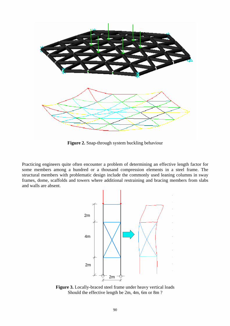
Figure 2. Snap-through system buckling behaviour
Practicing engineers quite often encounter a problem of determining an effective length factor for some members among a hundred or a thousand compression elements in a steel frame. The structural members with problematic design include the commonly used leaning columns in sway frames, dome, scaffolds and towers where additional restraining and bracing members from slabs and walls are absent.
Figure 3. Locally-braced steel frame under heavy vertical loads Should the effective length be 2m, 4m, 6m or 8m ?
2m
2m
2m
4m

91
3. SECOND-ORDER P-Δ-δ ELASTIC OR THE FIRST-PLASTIC HINGE ANALYSIS Second-order analysis can further be classified into P-Δ-only and P-Δ−δ analysis. The former more simple P-Δ−only analysis considers only change of nodal coordinates while the latter second-order P-Δ−δ analysis considers both the P-Δ effect and P-δ effect due to member curvature. In order to permit the section capacity check, one must allow for sway deflection in frames and bowing in members in an analysis. Their imperfections in the form of out-of-plumbness and member initial curvature must also be accounted for. The latest Hong Kong Steel Code [15] and the Eurocode-3 [1] have explicit requirements for these two imperfections. When these imperfections and load-induced second-order effects are considered, effective length and bending moment diagram plots are no longer required in the complete design process. This leads to a significant saving in design effort and in improving design efficiency, as well as a more rational distribution of material to members by realizing the ultimate strength and its influence to overall structural behaviour and stability. In the analysis, every member is checked along its length by the section capacity check as,
1)()(≤=
+Δ++
+Δ++ ϕ
δδ
Zy
zzz
Yy
yyy
y MPPM
MPPM
ApP (1)
where
Δ = nodal displacement due to out-of-plumbness frame imperfections plus sway induced
by loads in the frame
δ = displacement due to member curvature / bowing due to initial imperfection and load
at ends and along member length of a member. This is calculated using a curved
member [12].
A = cross sectional area
py = design strength
MYy, MZy = yield moments about principal Y- and Z-axes (i.e. Miy=py Zi, Z=elastic modulus)
My, Mz = external moments about principal Y- and Z-axes
ϕ = section capacity factor. If ϕ >1, member fails in section capacity check
For first plastic hinge design, the design load is considered to have been reached when φ is equal to 1. For collapse load analysis, a plastic hinge will then be inserted into the member end and the analysis continues until a plastic collapse mechanism is formed. 3.1 Imperfections in general The Eurocode 3 [1] and the Hong Kong Steel Code [15] give detailed guidelines on method of the second-order analysis allowing for initial imperfections in frames and in members. In summary, one must consider frame and member imperfections as follows.

92
3.2 Frame out-of-plumbness imperfection Frame imperfections can be considered by notional force or imperfect structural geometry obtained by an elastic critical analysis, as shown in Figure 4. For permanent structures, notional force equal to 0.5% of vertical force is applied horizontally to the structure to simulate out-of-plumbness. Figure 4a. Out-of-plumbness in actual structure Figure 4b. Equivalent notional forces 4. MEMBER BOWING IMPERFECTION Member imperfections must be considered by use of initially curved element or several straight elements to model a member. In both methods, the direction of curvature of a member should be in the adverse direction which follows the buckling direction. The use of several straight elements to model a member is not only to predict a more accurate buckling load calculation since straight element using cubic Hermite function cannot predict accurately the buckling load by one-element-per-member [16], but it is also used to approximate the location of maximum bending moment in a beam-column. Curved element based on stability function or PEP element allows for changing member curvature under load permits differentiation of shape function to locate the maximum bending moment as,
03
3
=∂∂
=∂
∂=
xv
xMV (2)
in which V is the shear, v is the lateral displacement, M is the bending moment along a member and x is coordinate along the line joining the two end nodes. Note that if displacement v from a cubic function is used, shear force V in Equation 1 becomes a constant and location of zero shear for maximum moment along a member cannot be determined. On the other hand, the stability function for curved members proposed by Gu and Chan [14] allows for the trible differentiation for maximum moment so that the zero shear location can be determined.
2φP P P P
P
φTransformation

93
4.1 Choice of element It is important to select a suitable element for second-order analysis of practical structures of which the number of elements is usually much larger than the examples studied in most research papers. When used for analysis of practical frames, computational truncating error and efficiency become paramount important. The use of several elements to locate approximately the maximum moment is usually not a good approach for steel frame design, in a similar argument as use of a finite element package in modelling a frame by shell elements which can hardly be used in a typical design office. A curved element possessing initial curvature is normally a much better choice in term of efficiency, robustness, reliability and accuracy. Zhou and Chan [16] proposed element suitable for plastic analysis and the element is refined here for plastic hinge analysis which is generally more suitable for large 3-dimensional structures. The PEP element is formulated on a higher order displacement function such that the stiffness matrix can predict the elastic buckling load accurately by one-element-per-member. Unlike the stability function, it does not require separated expressions for force in tension or in compression. The stiffness matrix is expressed as follows (see also Figure 5).
⎥⎦
⎤⎢⎣
⎡⎥⎦
⎤⎢⎣
⎡−
−=⎥
⎦
⎤⎢⎣
⎡
2
1
2212
1211
2
1 b
b
b
b
KKKK
LEI
MM
θθ
(3)
and
( )2
322
2211 80260,123
761800)80(3
q
qqqKK
+
⎟⎠
⎞⎜⎝
⎛+⎟⎠⎞
⎜⎝⎛++
== (4)
( )2
322
12 4842011
52928848
q
qqqK
+
⎟⎠⎞
⎜⎝⎛+⎟
⎠⎞
⎜⎝⎛++
= (5)
in which Mb1 and Mb2 are nodal moments and θb1 and θb2 are conjugate rotations, K11, K12 and K22
are stiffness coefficients. q is the non-dimensional axial force given by EI
PLq2
= , P is the axial force,
EI is the flexural constant and L is the element length. The element with springs at two ends can be written as,
⎥⎥⎥⎥⎥
⎦
⎤
⎢⎢⎢⎢⎢
⎣
⎡
⎥⎥⎥⎥⎥
⎦
⎤
⎢⎢⎢⎢⎢
⎣
⎡
−−+−
−+−−
=
⎥⎥⎥⎥⎥
⎦
⎤
⎢⎢⎢⎢⎢
⎣
⎡
cj
bj
bi
ci
jj
jjjjij
ijiiii
ii
cj
bj
bi
ci
SSSKSK
KKSSSS
M
MMM
θ
θθθ
(6)
in which Mci is the moment at connection and node “i”, Mbi is the moment at end node “i” of the beam. θci is conjugate rotation to moment Mci and Si is the spring stiffness at connection “i” obtained from the simple formula combining the effect of semi-rigid connection and plastic hinge as,
pici
picii SS
SSS
+= (7)
in which Sci and Spi are respectively spring stiffness for semi-rigid connection and plastic hinge at node “i”.

94
, cj
bj
cj
M bj
M cj
M cj
Connectionstiffness, S cj
(b) Additional internal nodes
(Deformed shape)
, biM bi
, ciM ci
, cjM cj
, bjM bj
(a) Element external nodes (Global nodes)
Node i Node j(Undeformed shape)
Figure 5. Beam-column element with end connection springs
After static condensation of Equation (2) for easy programming, the compact stiffness equation can be obtained as,
⎥⎥⎦
⎤
⎢⎢⎣
⎡
⎪⎪
⎭
⎪⎪
⎬
⎫
⎪⎪
⎩
⎪⎪
⎨
⎧
−++
⎥⎦
⎤⎢⎣
⎡⎥⎦
⎤⎢⎣
⎡+−
−+⎥⎦
⎤⎢⎣
⎡
−⎥⎦
⎤⎢⎣
⎡=⎥
⎦
⎤⎢⎣
⎡
cj
ci
c
c
KKSKS
SS
KSKKKS
SS
SS
MM
θθ
212222111
2
1
22212
12111
2
1
2
1
2
1
))((
00
00
00 (8)
In the analysis, the element is monitored on sectional strength using equation (1). Once the section capacity factor (φ) is larger than 1, the plastic hinge stiffness Sp at the end closer to the section with φ larger than 1 is assigned a very small number for simulation of plastic hinge and the analysis is continued until the large deflection plastic collapse mechanism is formed. If higher accuracy is required, the member with φ close to 1 or, in computer implementation, when φ is larger than 0.8, the member is sub-divided into several elements for better modeling of plastic behaviour. However, from several studied numerical examples for practical frames, this sub-division is unnecessary with small difference in most cases. If we consider both the P-δ and P-Δ effects, we then need not assume an effective length and the load capacity of a structure can then be determined by checking the sectional strength along a member.

95
4.2 Calibration against codes It is obvious that the magnitude of imperfection in the proposed method affects the buckling strength of a column or a beam-column. The values of imperfections have been rationally calibrated against the existing buckling curves in design codes and the following values were obtained and used in the new Hong Kong Steel Code [15]. δ0/L = 1/500 for curves “a” = 1/400 for curves “b” = 1/300 for curves “c” = 1/200 for curves “d” Figure 6 below shows an example of buckling design curve of a section against the Hong Kong Steel Code [15] curve “a”. Similar good results can be obtained for other buckling curves or in fact buckling curves in other national codes by adjusting the δ0. Note that δ0 is not only for modelling of geometrical imperfection, but it is also used to consider the equivalent material imperfection due to residual stress and their values are obtained by curve-fitting of various buckling curves in codes or in test series.
0.0
50.0
100.0
150.0
200.0
250.0
300.0
0 50 100 150 200 250 300 350Slenderness Le/r
Buck
ling
stre
ngth
p c
Nida Hong Kong Steel Code (2005) Euler Figure 6. Buckling design curves for Curve “a” for hollow sections
5. EXAMPLES Two examples are given here to demonstrate the application of the design method for hypothetical and real structures. The software Nida is used for all the two examples as most software available in market at the time of article is limited to P-Δ only analysis using straight cubic elements. As mentioned previously, the use of several straight elements can theoretically model a member for accurate but approximated location of section with maximum combined axial force and moment check in Equation 1. This finite element approach was noted to be deficient in many practical applications because of easy divergence due to use of numerous elements leading to truncating numerical error, especially when the limit load is approached. A simple test is suggested for finding of the buckling strength of a pin-fixed imperfect column against the code-permitted load as in the calibration exercise in the last section.

96
Example 1 Design of a portal braced at one storey The example below is an illustrative problem for second-order analysis of a simple plane frame. A similar problem was used in the USA as a benchmark example for verifying the accuracy of a design method since the effective length is not obvious. The size of the members is shown in Figure 7 and the steel grade is taken as 275 N/mm2 and the frame is under a pair of vertical point loads of 500 kN each. Elastic modulus is used for the section capacity check in Equation 1.
Figure 7. Plane frame braced at upper storey
The direct use of hand method is very uneconomical here since the lower storey makes the frame to be classified as sway while the upper storey column use this effective length factor for design. Further, the whole frame has a low elastic critical load factor of 1.77 to prohibit the use of the first-order linear analysis. This type of structure can be common for supporting heavy loads on top and providing high clearance at lower storey. In the analysis, a horizontal notional force of 0.5% of the vertical load is applied to the level of the vertical load. However, for braced system such as the one discussed here, the notional force may not generate an effect as severe as using the buckling mode as imperfection shape, since the force is transferred by braces to other parts of the structure and thus the magnitude of the top deflection is not so significant. The ultimate load of the frame is obtained from Figure 8 as 0.99 which is represented by the peak or limit load in the load vs. deflection plot. If the buckling mode imperfection of magnitude equal to 0.5% of the frame height or 40mm is used, the collapse load as the limit load in the load vs. deflection curve becomes 0.80 which is 19% below the notional force method (see Figure 9). The selected node obtained from a buckling analysis for applying the initial displacement is at the top node. The load vs deflection curves by notional force method and by buckling mode as imperfection are indicated in Figures 9 and 10. The collapse loads are close to the first yield load since it has little redundancy after buckling of the first column. This indicates the plastic strength reserve is
500kN500kN
5m
3m
4m
152x152x30UC grade S275(43)
120x120x10L grade S275(43)
Pin Supports
97
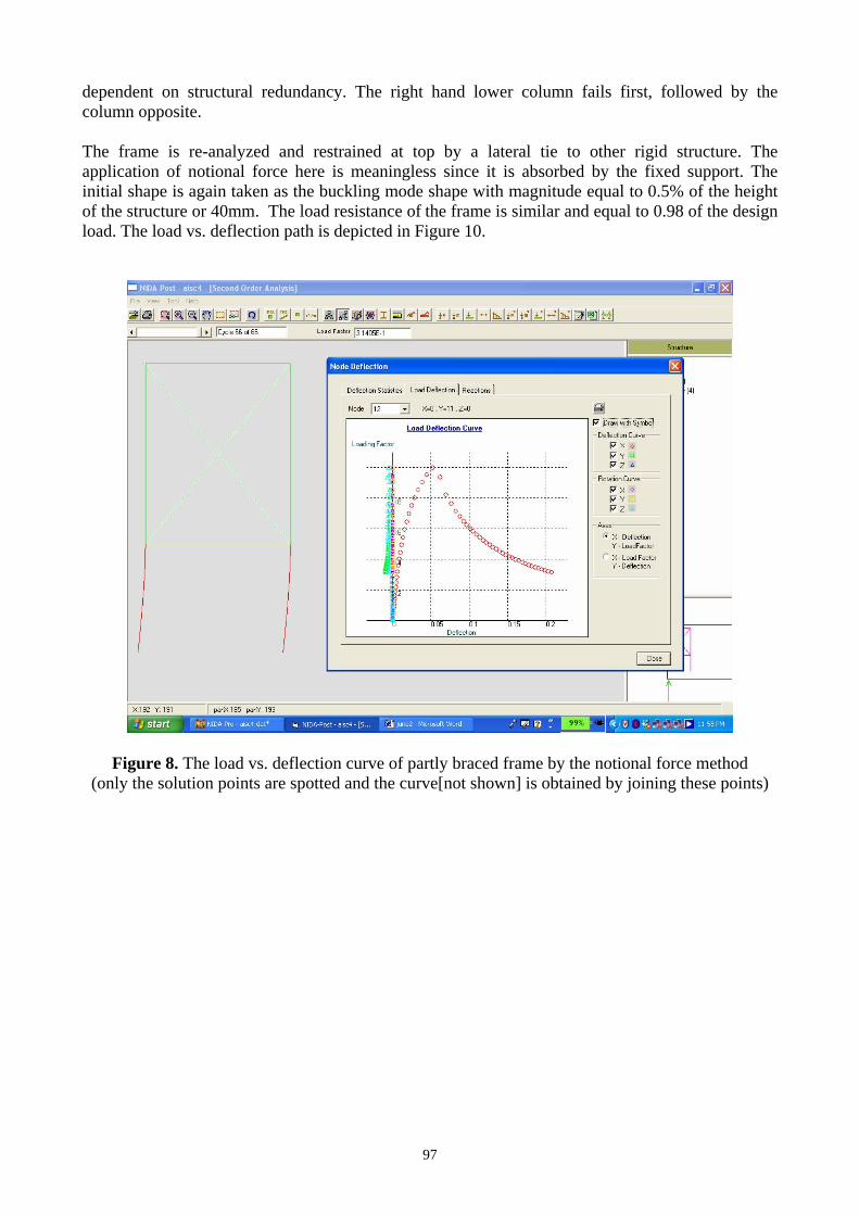
dependent on structural redundancy. The right hand lower column fails first, followed by the column opposite. The frame is re-analyzed and restrained at top by a lateral tie to other rigid structure. The application of notional force here is meaningless since it is absorbed by the fixed support. The initial shape is again taken as the buckling mode shape with magnitude equal to 0.5% of the height of the structure or 40mm. The load resistance of the frame is similar and equal to 0.98 of the design load. The load vs. deflection path is depicted in Figure 10.
Figure 8. The load vs. deflection curve of partly braced frame by the notional force method (only the solution points are spotted and the curve[not shown] is obtained by joining these points)

98
Figure 9. Load vs. deflection path of partly braced frame by the elastic
eigen-buckling mode imperfection
Figure 10. Load vs deflection curve of unbraced but tied-at-top frame

99
From the results of this example, it can be seen that inclusion of initial imperfection is important in determining the resistance of a structure. The recommended use of 0.5% of storey height for permanent structures and 1% for temporary structure are commonly used in practice. Engineers should inspect structures against excessive imperfections to prevent unexpected collapse. Example 2 Advanced analysis of a bracket-ball stadium A bracket ball stadium of 48m(L)x40.4m(W)x16.7m(H) is designed by the advanced analysis. The steel grade used is S355J and all are hollow sections. The computer model of the structure is indicated in Figure 11 with photographs on the structure during early and late construction stages are shown in Figures 12 and 13. All connections between members are welded and assumed rigid in the analysis model.
Figure 11. Computer model of the stadium
For simplicity, only the load case consisted of live loads of 1.5 kPa, dead loads of self weigh plus 0.75 kPa for accessories and wind load parallel to the longer dimension is considered. All load factors used are 1.2. The second-order plastic hinge analysis is used in the present design. Notional force is not applied to the frame as it is smaller than wind load.
Figure 12. Stadium under construction

100
Figure 13. Inside view of the completed stadium
First plastic hinge is formed at 80% of the design load and the deflection curves become flat at a load factor of 1.06 of the design load. This implies around 26% strength reserve can be obtained when advanced or second-order plastic hinge analysis is used. Figure 14 shows the red members possessing plastic hinges at the maximum load factor.
Figure 14. Plot for maximum load of the stadium indicating around 20% plastic strength
reserve after the first plastic hinge

101
When using the elastic or first plastic hinge analysis, engineers are frustrated when an obviously redundant member fails in section capacity check but the first plastic hinge design does not permit further increase in design load. Significant gain in economy can be achieved if we fix the plastic strength of the member and continue the incremental load analysis. More importantly, material used for constructing the frame can be better distributed when the ultimate behaviour is known. This influence of a member yielding may be detrimental for determinate structures such as the frame in example 1 and the level of structural robustness can be assessed scientifically by the present design method. Furthermore, the design speed is significantly improved by the present method since one needs not assume effective length factor (Le/L) for each member for safety and economy. The complete analysis and design process take 2 minutes and 12 seconds for a load case when using a portable personal computer of 1.6 GHz and the computer time will obviously be further reduced when faster computers are used and available. When using the first order linear analysis with all members having an effective length factor (Le/L) of 1.0 which is a normal value adopted by engineers when buckling mode is uncertain, the design load resistance factor is only 0.46 of the design load. This is significantly less than the first-plastic hinge load of 0.80 and the collapse load factor of 1.06. 6. CONCLUSIONS This paper presents an alternative and robust practical design method allowing for moment re-distribution after the first plastic hinge in steel structures. The method has been applied to accurate and reliable buckling analysis and design of real steel structures of moderate size and for design allowing for plastic strength reserve after the first plastic hinge. As all structures have different levels of integrity, robustness and plastic strength reserve, the proposed method can be used to identify the ultimate collapse strength instead of the strength at first-plastic moment in a structure and to improve building scheme, as well as to enhance safety and economy through better understanding of structural behaviour at various limit states. The authors further suggested no yielding and excessive deflection should be allowed at working or serviceability limit load and the structure should not collapse under the factored ultimate limit load. The computer method for determination of this collapse load allowing for the effects of member buckling, system instability, and formation of plastic hinges is detailed in this paper with an illustrative example of practical application. From the authors’ experience designing a number of steel structures, the “advanced analysis” was noted to be more efficient and convenient. The time required for assessing the effective length factor (Le/L) for all compression members is saved. In some cases, the effective length factor (Le/L) may be impossible to determine using code method. However, it appears that most engineers may require to attend an additional course on training of concept and computational skill on non-linear second-order and advanced analysis, which is not covered by general civil engineering courses. 7. ACKNOWLEDMENT The first author would like to express his sincere thanks to Mr. Eddie Wong of Eddie Wong and Associates Limited for his kind permission of using one of the steel structures constructed for the East Asian Game in Macau as the second example as an illustrative example in this paper.
102
REFERENCES [1] European Standard, Eurocode 3, “Design of steel structures”, En1993-3-1-1, 2003. [2] British Standards Institution, BS5950, “Structural Use of Steel in Building”, Part 1, 2000. [3] Australian Standards AS4100, “Steel Structures”, Standards Association of Australia,
Sydney, Australia, 1996. [4] Chen, W.F. and Lui, E.M., “Stability design of steel frames”, CRC, Boca Raton, 1991,
pp.380. [5] Liew, J.Y.R., White, D.W. and Chen, W.F., “National load plastic-hinge method for frame
design”, Journal of Structural Engineering, ASCE, 1990, 120(5), pp.1434-1454. [6] White, D.W. and Hajjar, J.F., “Buckling Models and Stability Design of Steel Frames: a
Unified Approach”, Journal of Constructional Steel Research, 1997, 42(3), pp.171-207. [7] Barreto, V. and Camotim, D., “Computer-Aided Design of Structural Steel Plane Frames
According to Eurocode 3”, Journal of Constructional Steel Research, 1998, 46(1-3), pp.367-368.
[8] Liew, J.Y.R., Chen, W.F., Chen, I.H., “Advanced inelastic analysis of frame structures”, Journal of Constructional Steel Research, 2000, 55(1-3), pp.245-265.
[9] Xu, L., “The buckling loads of unbraced PR frames under non-proportional loading”, Journal of Constructional Steel Research, 2002, 58(4), pp.443-465.
[10] Li, G.Q. and Li, J.J., “A tapered Timoshenko-Euler beam element for analysis of steel portal frames”, Journal of Constructional Steel Research, 2002, 58(12), pp.1531-1544.
[11] Goncalves, R. and Camotim, D., “Design of plane steel frames – towards a rational approach”, Advanced Steel Construction, June, 2005, 1(1), pp.105-128.
[12] Chan, S.L. and Zhou, Z.H., “Non-linear integrated design and analysis of skeletal structures by 1 element per member”, Engineering Structures, 2000, 22, pp.246-257.
[13] Chan, S.L. and Cho, S.H., “Second-order P-delta analysis and design of angle trusses allowing for imperfections and semi-rigid connections”, Advanced Steel Construction, June, 2005, 1(1), pp.151-171.
[14] Gu, J.X. and Chan, S.L., “Design of frames with imperfect members and global geometry by second-order analysis with section capacity check”, International Journal for Numerical Methods in Engineering, 2005, 62, pp.601-615.
[15] Buildings Department, “Code of Practice for the Structural Use of Steel”, Hong Kong, 2005. [16] Zhou, Z.H. and Chan, S.L., “Elastoplastic and large deflection analysis of steel frames by
one element per member. Part 1: One hinge along member”, Journal of Structural Engineering, ASCE, 2004, 130(4), pp.538-544.