Advance Optima Module Uras 14 - ABB Group = IR module Figure 1-3 Outline diagram of fully equipped...
85
Advance Optima Module Uras 14 Service Manual 43/24-1005-0 EN
Transcript of Advance Optima Module Uras 14 - ABB Group = IR module Figure 1-3 Outline diagram of fully equipped...

Advance OptimaModule Uras 14
Service Manual 43/24-1005-0 EN
SDE_U14 Uras 14 Module Service Documentation iii
Table of Contents
PageChapter 1: Description of Functions 1-1
Chapter 2: Analyzer Module Variants 2-1
Chapter 3: Module Components 3-1
Chapter 4: Troubleshooting (being prepared) 4-1
Chapter 5: Testing (being prepared) 5-1
Chapter 6: Component Interchange 6-1
Chapter 7: Calibration (being prepared) 7-1
Chapter 8: Configuration (being prepared) 8-1
Chapter 9: Parts Catalog 9-1
SDE_U14 Chapter 1: Description of Functions 1-1
Chapter 1: Description of functions
Overview
This chapter ... describes the underlying physical principles and provides information on thedetermination of influence values.
Chapter contents You will find the following information in this chapter:
Subject See pagePhysical principles 1-2Determination of influence values 1-6Ex Concept (being prepared) 1-7
1-2 Chapter 1: Description of Functions SDE_U14
Physical principles
Measurementprinciple
• NDIR Technique(Non-Dispersive InfraRed Analysis)
• The measurement effect is based on resonance absorption of gas-specificvibration-rotation bands of gas molecules with differing atoms in the medianinfrared spectrum at wavelengths between 2.8 and 8 µm.
• The individual gases to be measured are identified by their specific absorptionbands. Each gas has such an absorption spectrum (fingerprint).Exceptions:- Monoatomic gases, such as inert gases- Symmetrical gases, such as N2, O2 and H2
- These types of gases cannot be measured with this method.The relationship between measured infrared emission absorption and the samplecomponent is based on the LAMBERT-BEER law:
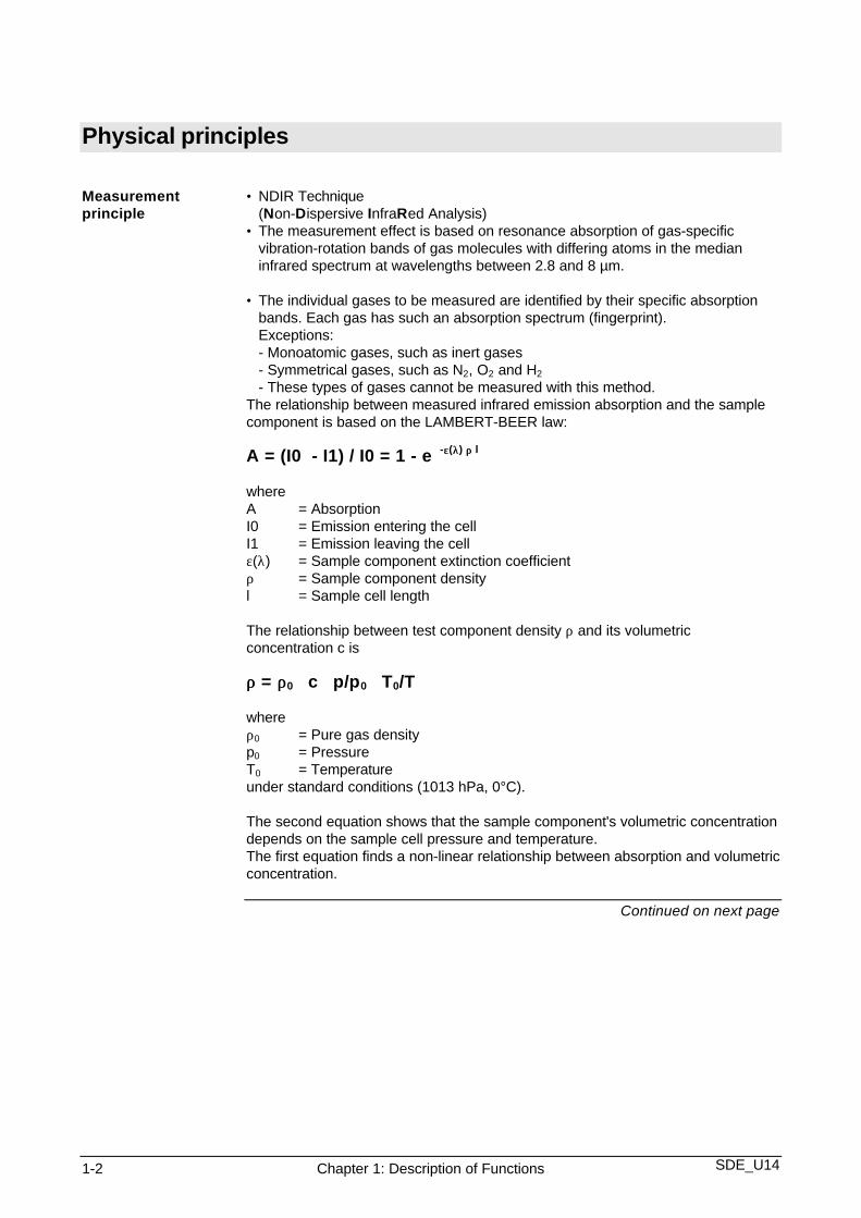
A = (I0 - I1) / I0 = 1 - e -εε(λλ)⋅⋅ρρ⋅⋅l
whereA = AbsorptionI0 = Emission entering the cellI1 = Emission leaving the cellε(λ) = Sample component extinction coefficientρ = Sample component densityl = Sample cell length
The relationship between test component density ρ and its volumetricconcentration c is
ρρ = ρρ0 ⋅⋅ c ⋅⋅ p/p0 ⋅⋅ T0/T
whereρ0 = Pure gas densityp0 = PressureT0 = Temperatureunder standard conditions (1013 hPa, 0°C).
The second equation shows that the sample component's volumetric concentrationdepends on the sample cell pressure and temperature.The first equation finds a non-linear relationship between absorption and volumetricconcentration.
Continued on next page

SDE_U14 Chapter 1: Description of Functions 1-3
Physical principles, continued
Basic design • The Uras 14 analyzer module is a twin-beam NDIR process photometer withno dispersive elements.The module consists of a completely self-contained optical unit with thefollowing elements:
• Infrared source (emitter)• Chopper wheel• Emitter aperture• Sample cell with sample and reference chambers• Infrared detector with diaphragm capacitor
Figure 1-1Measurementprinciple
N2
21 3 4 5 6
COCO
7 8
1 Emitter2 Emitter aperture3 Chopper wheel4 Sample cell5 Sample chamber6 Reference chamber7 Infrared detector8 Diaphragm capacitor
1-4 Chapter 1: Description of Functions SDE_U14
Physical principles, continued
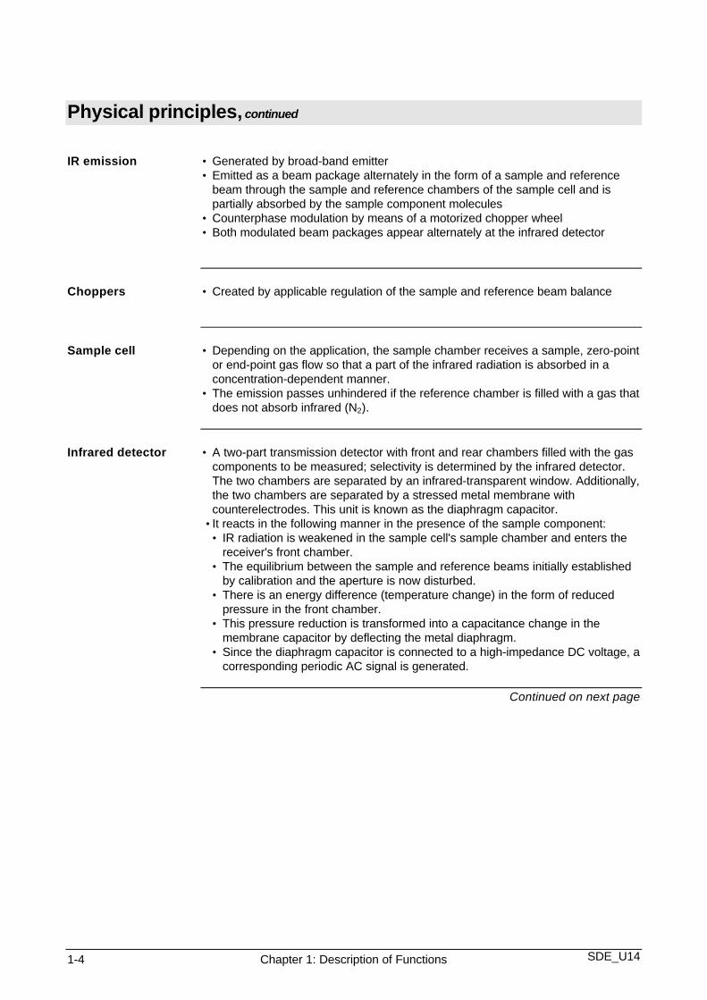
IR emission • Generated by broad-band emitter• Emitted as a beam package alternately in the form of a sample and reference
beam through the sample and reference chambers of the sample cell and ispartially absorbed by the sample component molecules
• Counterphase modulation by means of a motorized chopper wheel• Both modulated beam packages appear alternately at the infrared detector
Choppers • Created by applicable regulation of the sample and reference beam balance
Sample cell • Depending on the application, the sample chamber receives a sample, zero-pointor end-point gas flow so that a part of the infrared radiation is absorbed in aconcentration-dependent manner.
• The emission passes unhindered if the reference chamber is filled with a gas thatdoes not absorb infrared (N2).
Infrared detector • A two-part transmission detector with front and rear chambers filled with the gascomponents to be measured; selectivity is determined by the infrared detector.The two chambers are separated by an infrared-transparent window. Additionally,the two chambers are separated by a stressed metal membrane withcounterelectrodes. This unit is known as the diaphragm capacitor.
• It reacts in the following manner in the presence of the sample component:• IR radiation is weakened in the sample cell's sample chamber and enters the
receiver's front chamber.• The equilibrium between the sample and reference beams initially established
by calibration and the aperture is now disturbed.• There is an energy difference (temperature change) in the form of reduced
pressure in the front chamber.• This pressure reduction is transformed into a capacitance change in the
membrane capacitor by deflecting the metal diaphragm.• Since the diaphragm capacitor is connected to a high-impedance DC voltage, a
corresponding periodic AC signal is generated.
Continued on next page
SDE_U14 Chapter 1: Description of Functions 1-5
Physical principles, continued
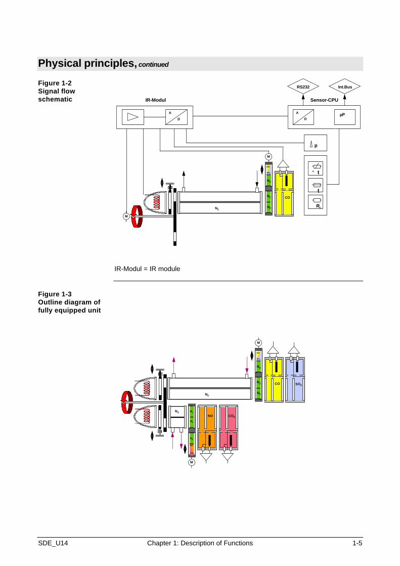
Figure 1-2Signal flowschematic
A
DµP
RS232 Int.Bus
A
D
CO
N2
N2
N2
N2
CO
SO2
M
M
IR-Modul Sensor-CPU
p
t
Rt
t
IR-Modul = IR module
Figure 1-3Outline diagram offully equipped unit
N2
CO SO2
NO
N2
N2
N2
N2
CO
SO2
N2
N2
N2
NO
CO2
CO2
M
M

1-6 Chapter 1: Description of Functions SDE_U14
Determination of influence values
Associated gaseffects
The sample gas is a mixture of the sample component and associated gascomponents. If the infrared absorption bands of one or more associated gascomponents overlap the sample component's bands, the test results will beaffected.The influence of interfering gas components is termed cross sensitivity or carriergas dependence.Cross sensitivity is determined by connecting an inert gas (e.g. N2) which is mixedwith the interfering gas components (corresponding to the test gas).The influence acts on the zero-point measurement value indication.Carrier gas dependence, which is rarely observed, occurs when the physicalproperties of the sample gas differ markedly from those of the test gas. Thisinterference changes the slope of the device's characteristic curve. This curve iscorrected at the end-point.The Uras 14 has the following methods available for interference correction:• Interference filter• Filter cells• Internal electronic cross-sensitivity correction• Internal electronic carrier gas correction
Pressure According to the gas laws, the sample cell's volumetric concentration depends onthe pressure in the sample cell and is thus dependent on the process gas and airpressure. This effect acts on the end-point and amounts to approx. 1% of themeasurement value per 1% of pressure change (therefore, per 10 hPa).An internal pressure sensor reduces this effect to 0.2%.
Flow rate The flow rate affects pressure in the sample cell and the module's T90 times.The flow rate should be between 20 and 100 liters/hour.
Temperature Temperature has a markedly different effect on all optical components in the beampath. This effect is reduced by:• Temperature compensation
A temperature sensor in the first infrared detector's preamplifier measures thetemperature in the module.This signal is used for electronic correction.Zero-point effect: ≤ 1% of the measurement range per 10°CEnd-point effect: ≤ 3% of the measured value per 10°C
• Thermostat (optional)Zero-point effect: ≤ 1% of the measurement range per 10°CEnd-point effect: ≤ 1% of the measured value per 10°C
SDE_U14 Chapter 1: Description of Functions 1-7
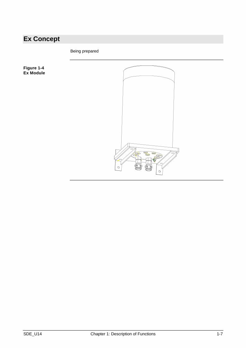
Ex Concept
Being prepared
Figure 1-4Ex Module

SDE_U14 Chapter 2: Analyzer Module Variants 2-1
Chapter 2: Analyzer module variants
Overview
Introduction This chapter describes the individual module variants.
Chapter contents You will find the following information in this chapter
Subject See pageSummary 2-2Module variants 2-4Hose and piping connections 2-6

2-2 Chapter 2: Analyzer Module Variants SDE_U14
Summary
General Depending on the measurement application, the Uras 14 Analyzer can beequipped with the following main components:• 1 to 4 infrared detectors• 1 to 2 beam paths• Up to 2 infrared detectors per beam path• The following elements are permanently installed
•Both emitter inserts are filled •There is hardware support for installation of a thermostat •IR module circuit board •Sensor-CPU circuit board •Pressure sensor circuit board
• Other components are fitted according to the measurement application orconfiguration ordered.
• Any version of the module can be installed in a 19" rack or wall housing withoutspecial conversion.
• The pneumatics module and oxygen analyzer module can be incorporatedtogether in the gas path.
Special components The following components can be fitted according to the option ordered ormeasurement task to be carried out:• 1 to 2 calibration units• 1 to 2 filter cells• Optics filter• Gas paths
• FPM hose• PTFE hose• Stainless steel pipe
Figure 2-1Uras 14Analyzer Module
1 Connection plate with electrical and gas connections2 Sensor electronics3 Optical analyzer components with heat hood
Continued on next page
SDE_U14 Chapter 2: Analyzer Module Variants 2-3
Summary, continued
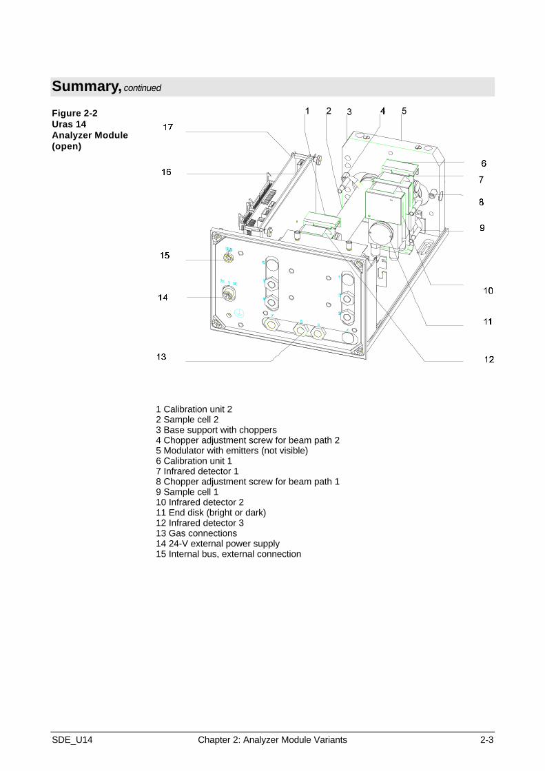
Figure 2-2Uras 14Analyzer Module(open)
1 Calibration unit 22 Sample cell 23 Base support with choppers4 Chopper adjustment screw for beam path 25 Modulator with emitters (not visible)6 Calibration unit 17 Infrared detector 18 Chopper adjustment screw for beam path 19 Sample cell 110 Infrared detector 211 End disk (bright or dark)12 Infrared detector 313 Gas connections14 24-V external power supply15 Internal bus, external connection
2-4 Chapter 2: Analyzer Module Variants SDE_U14
Module variants
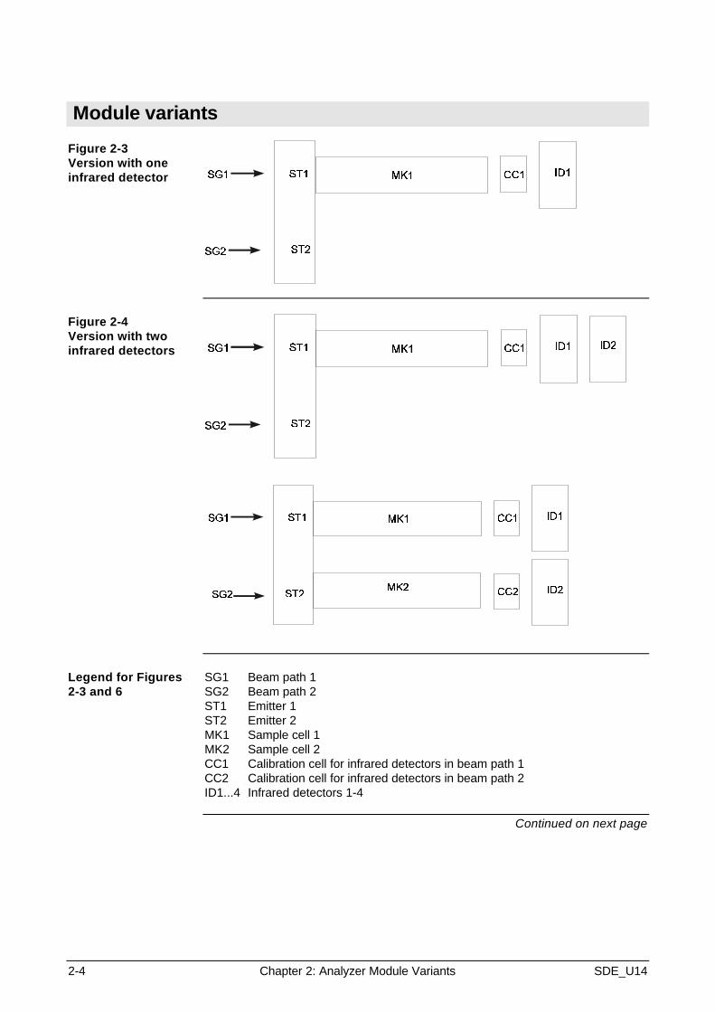
Figure 2-3Version with oneinfrared detector
Figure 2-4Version with twoinfrared detectors
Legend for Figures2-3 and 6
SG1 Beam path 1SG2 Beam path 2ST1 Emitter 1ST2 Emitter 2MK1 Sample cell 1MK2 Sample cell 2CC1 Calibration cell for infrared detectors in beam path 1CC2 Calibration cell for infrared detectors in beam path 2ID1...4 Infrared detectors 1-4
Continued on next page

SDE_U14 Chapter 2: Analyzer Module Variants 2-5
Module variants, continued
Figure 2-5Version with threeinfrared detectors
Figure 2-6Version with fourinfrared detectors
Familiarity with the arrangement of the individual elements is needed for thefollowing tasks:
• Troubleshooting• Configuration• Optical alignment• Phase alignment
2-6 Chapter 2: Analyzer Module Variants SDE_U14
Hose and piping connections (still being supplemented)
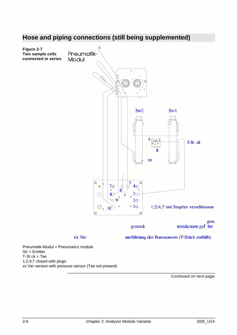
Figure 2-7Two sample cellsconnected in series
Pneumatik-Modul = Pneumatics moduleStr = EmitterT-St ck = Tee1;2;4;7 closed with plugsxx Ver version with pressure sensor (Tee not present)
Continued on next page

SDE_U14 Chapter 2: Analyzer Module Variants 2-7
Hose and piping connections (still being supplemented), Continued
Figure 2-8Two sample cellswith flowingreference gas
Str = EmitterT-St ck = TeeX b … inserted and placed in electronics compartmentTwo cells, reference gas and pressure sensor; No PA module
Continued on next page
2-8 Chapter 2: Analyzer Module Variants SDE_U14
Hose and piping connections (still being supplemented), continued
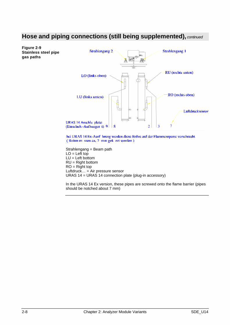
Figure 2-9Stainless steel pipegas paths
Strahlengang = Beam pathLO = Left topLU = Left bottomRU = Right bottomRO = Right topLuftdruck… = Air pressure sensorURAS 14 = URAS 14 connection plate (plug-in accessory)
In the URAS 14 Ex version, these pipes are screwed onto the flame barrier (pipesshould be notched about 7 mm)

SDE_U14 Chapter 3: Module Components 3-1
Chapter 3: Module components
Overview
Introduction This chapter describes the individual assemblies and components.
Chapter contents You will find the following information in this chapter:
Subject See pageEmitter 3-2Modulator 3-3Choppers 3-6Sample cell 3-7Filter cell 3-10Optics filter 3-11Calibration unit 3-12Calibration cell 3-14Infrared detector 3-15IR module circuit board 3-18Sensor-CPU circuit board 3-22Pressure sensor circuit board 3-27Thermostat circuit board 3-28Hood with supplemental heater 3-29Connecting cable 3-30
3-2 Chapter 3: Module Components SDE_U14
Emitter
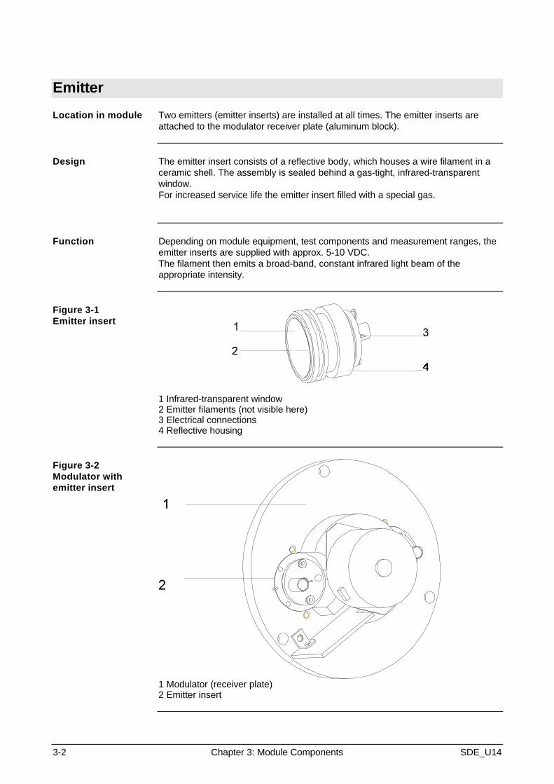
Location in module Two emitters (emitter inserts) are installed at all times. The emitter inserts areattached to the modulator receiver plate (aluminum block).
Design The emitter insert consists of a reflective body, which houses a wire filament in aceramic shell. The assembly is sealed behind a gas-tight, infrared-transparentwindow.For increased service life the emitter insert filled with a special gas.
Function Depending on module equipment, test components and measurement ranges, theemitter inserts are supplied with approx. 5-10 VDC.The filament then emits a broad-band, constant infrared light beam of theappropriate intensity.
Figure 3-1Emitter insert
1 Infrared-transparent window2 Emitter filaments (not visible here)3 Electrical connections4 Reflective housing
Figure 3-2Modulator withemitter insert
1 Modulator (receiver plate)2 Emitter insert

SDE_U14 Chapter 3: Module Components 3-3
Modulator
Location in module The modulator is fastened to the base support with the chopper adjustment.
Design The modulator consists of:• Receiver plate, on which all components are mounted• 2 emitter inserts• Chopper wheel• Synchronous motor to drive the chopper wheel• Coupling between synchronous motor and chopper wheel• Circuit board with
• Emitter power supply connectors• Synchronous motor connector• Split light barrier• O rings to seal the emitter inserts and the entire modulator assembly
Function The computer-controlled synchronous motor drives the chopper wheel.Modulation rate: 7.3 Hz (standard setting).The motorized chopper wheel is designed to alternately cover the test andreference chambers in the sample cell so that infrared light from the emitterspasses alternately through each chamber twice per revolution.This alternating arrangement is assured by the split light barrier fastened to themotor shaft by means of a lug.This design solution creates modulated light which results in a highly stablemeasurement signal.
Figure 3-3Modulator
1 Chopper wheel2 Synchronous motor3 Emitter circuit board4 Emitter inserts5 Receiver plate
Continued on next page

3-4 Chapter 3: Module Components SDE_U14
Modulator, continued
Figure 3-4ModulatorChopper wheel
1 Emitter 22 Chopper wheel aperture to reference chamber3 Emitter 14 Chopper wheel aperture to test chamber
Continued on next page

SDE_U14 Chapter 3: Module Components 3-5
Modulator, continued
Figure 3-5Emitter circuit board
U1 Split light barrier
Inputs/Outputs X1 Connection to IR module circuit boardX2 Synchronous motorX3 Emitter 1X4 Emitter 2
Figure 3-6Pin layout
3-6 Chapter 3: Module Components SDE_U14
Choppers
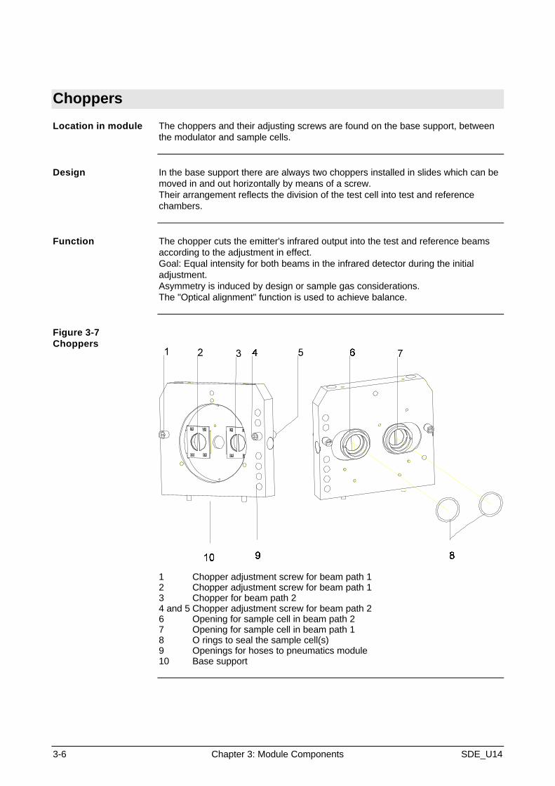
Location in module The choppers and their adjusting screws are found on the base support, betweenthe modulator and sample cells.
Design In the base support there are always two choppers installed in slides which can bemoved in and out horizontally by means of a screw.Their arrangement reflects the division of the test cell into test and referencechambers.
Function The chopper cuts the emitter's infrared output into the test and reference beamsaccording to the adjustment in effect.Goal: Equal intensity for both beams in the infrared detector during the initialadjustment.Asymmetry is induced by design or sample gas considerations.The "Optical alignment" function is used to achieve balance.
Figure 3-7Choppers
1 Chopper adjustment screw for beam path 12 Chopper adjustment screw for beam path 13 Chopper for beam path 24 and 5 Chopper adjustment screw for beam path 26 Opening for sample cell in beam path 27 Opening for sample cell in beam path 18 O rings to seal the sample cell(s)9 Openings for hoses to pneumatics module10 Base support
SDE_U14 Chapter 3: Module Components 3-7
Sample cell
Location in module The sample cell is installed between the base support with modulator and theinfrared detector or calibration unit.
Design The cell consists of a gold-plated, special-section tube. A land divides it into asample and a reference chamber. The chambers are closed off at both ends withinfrared-transparent windows. As standard equipment, the reference chamber isfilled with N2. Two gas inlets allows the sample gas to flow through the samplechamber. The gas inlets are designed for the connection of piping or hoses.Positioning dowels hold the sample cells firmly in the beam path. For designreasons, shorter sample cells have additional N2 -filled chambers in the sampleand reference beams.
Function Cell length depends on the measurement range involved.Since infrared detectors for the components being measured have an assignedsignal output, absorption adjustment according to the Lambert-Beer Law has totake place in the sample cell. Infrared light absorption depends on theconcentration to be measured (measurement range) and the optical path length.The optical path length is the distance between the two windows in the sample andreference chambers.The gold plating on the chamber surfaces serves the following purpose:• Optimal light reflection • Corrosion protection for the cellReflective properties are taken into consideration during optical alignment andcalibration.There are special sample cells for specific applications:• Sample cells with flowing reference gas
In this application the reference chamber can receive a sample gas flow (withoutthe sample component). Result: Absorption of the portion of light in theinterference gas absorption line region. This occurs equally in both chamberportions. There is no cross sensitivity.∆ measurements are another application.
• Sample cell with integrated filter cellHere, both filter chambers (sample and reference side) are filled with theinterference gas component.Here, the light portion in the interfering gas line range is absorbed to suppressthe interfering gas effect (cross sensitivity).
Variants The nominal length is the optical path between the insides of the two windows.
NL (Nominallength)
mm
Hoseconnection
Pipeconnection
Flowingreference gas
0.3 X X -0.6 X X -2 X X -6 X X X
20 X X X60 X X X200 X X X
Continued on next page
3-8 Chapter 3: Module Components SDE_U14
Sample cell, continued
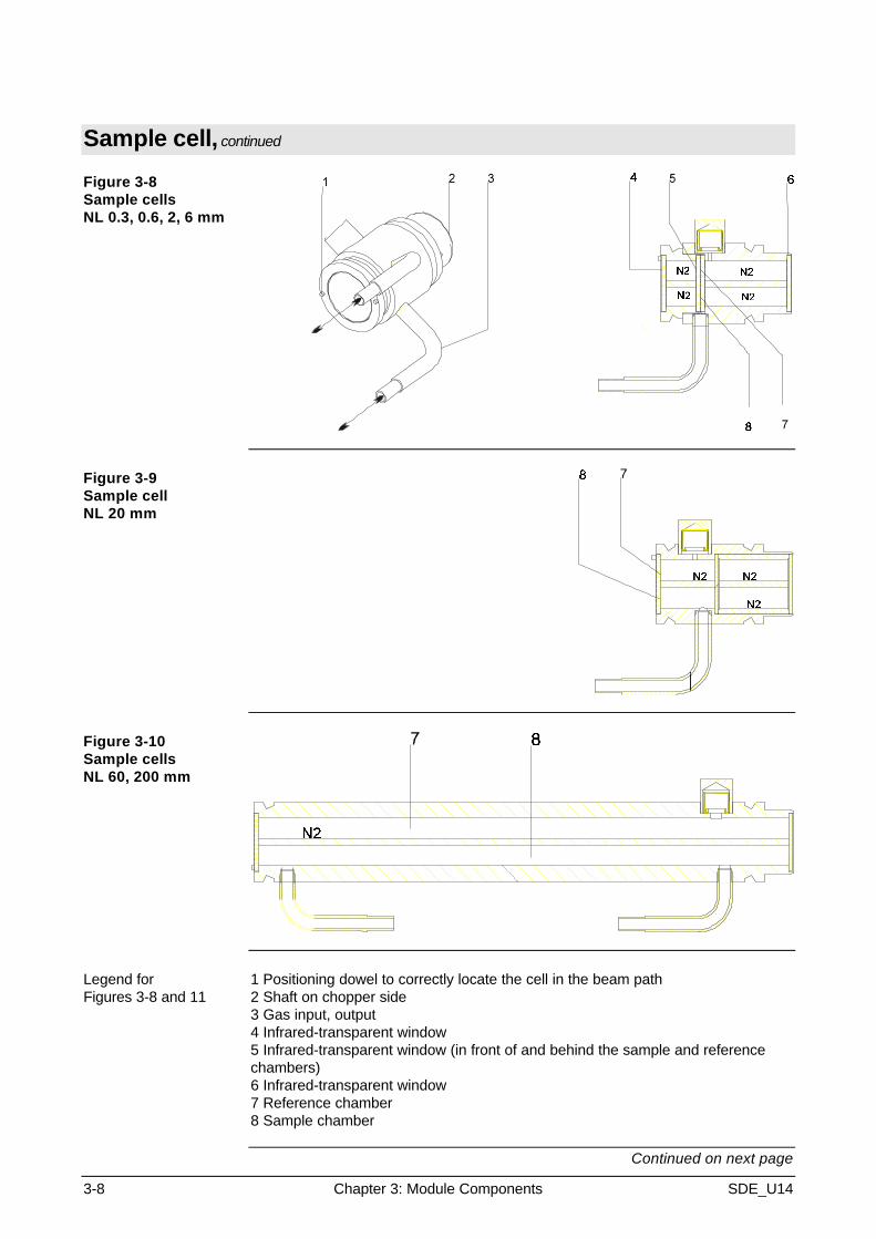
Figure 3-8Sample cellsNL 0.3, 0.6, 2, 6 mm
Figure 3-9Sample cellNL 20 mm
Figure 3-10Sample cellsNL 60, 200 mm
Legend forFigures 3-8 and 11
1 Positioning dowel to correctly locate the cell in the beam path2 Shaft on chopper side3 Gas input, output4 Infrared-transparent window5 Infrared-transparent window (in front of and behind the sample and referencechambers)6 Infrared-transparent window7 Reference chamber8 Sample chamber
Continued on next page
SDE_U14 Chapter 3: Module Components 3-9
Sample cell, continued
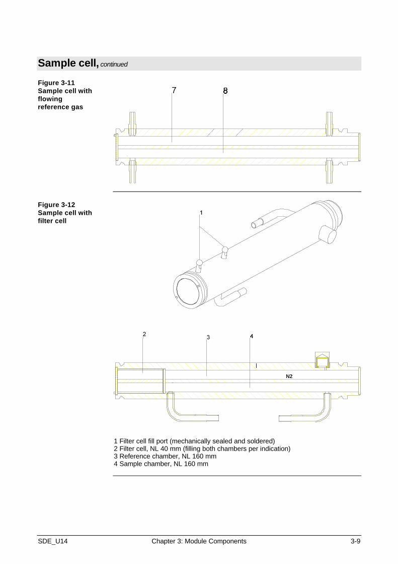
Figure 3-11Sample cell withflowingreference gas
Figure 3-12Sample cell withfilter cell
1 Filter cell fill port (mechanically sealed and soldered)2 Filter cell, NL 40 mm (filling both chambers per indication)3 Reference chamber, NL 160 mm4 Sample chamber, NL 160 mm

3-10 Chapter 3: Module Components SDE_U14
Filter cell
Location in module The filter cell is mounted between the sample cell and the infrared detector orbetween the sample cell and the calibration cell.
Design The filter cell consists of a gold-plated, special section tube.A land divides it into sample and reference chambers with a gas connectionbetween them.The filter cell is closed off at both ends with infrared-transparent windows.Two positioning dowels hold the filter cell properly in the beam path.
Function The sample and reference sides are individually filled with the correspondinginterference gas.This causes absorption of the beam portion within the range of the interfering gasabsorption lines.Result: A marked reduction in cross sensitivity.
Figure 3-13Filter cellNL 60 mm
SDE_U14 Chapter 3: Module Components 3-11
Optics filter
Location in module Depending on the module arrangement and measurement task involved, theoptical filters are placed in the following locations:between Sample cell and infrared detector
Two infrared detectorsCalibration unit and infrared detector
Design The optical filter (interference filter) consists of a silicon disk with varying degreesof metallic dampening depending on the desired properties.The filter is clamped in a metal socket.The design of the sockets varies according to the sites listed above.
Function Emission ranges in the sample and interference band overlap regions arediminished by installing interference filters. This means that certain filter types onlyallow specific wavelengths to pass.For reasons of symmetry, the filter acts on the sample and reference sides of thebeam path.Use of filters is dependent on the following marginal conditions:Combination of gas components in the sample gasComponent concentrationsMeasurement rangesFilters are primarily used for the SO2, NO, N2O, and CnHm components.
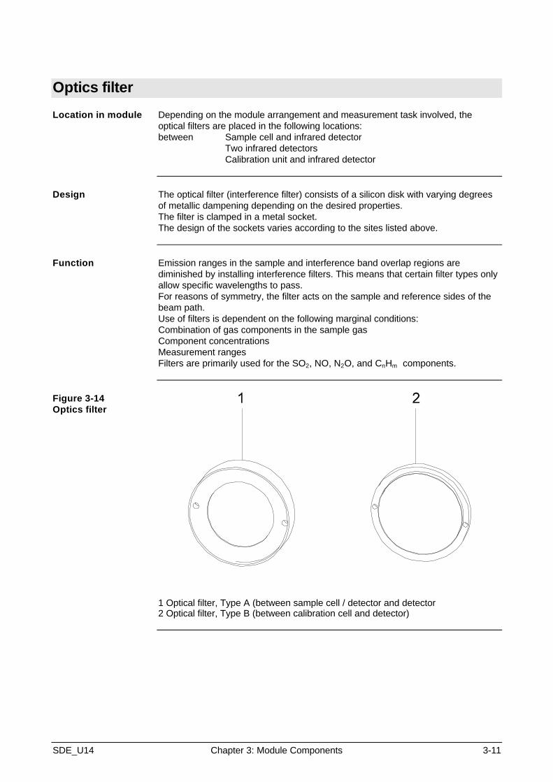
Figure 3-14Optics filter
1 Optical filter, Type A (between sample cell / detector and detector2 Optical filter, Type B (between calibration cell and detector)

3-12 Chapter 3: Module Components SDE_U14
Calibration unit
Location in module The calibration unit is an option.It is installed between the sample cell and infrared detector.
Design The calibration device is a motor-driven slide system for the calibration cell.A small geared motor with a drive pin moves a slide block.Small permanent magnets are used to improve calibration cell positioning andfastening.Two U-clamps are used to attach the cell. Different versions are provided for usewith and without an optical filter.
Figure 3-15Calibration unit
1 Calibration cell2 Connector circuit board3 Geared motor4 & 5 Permanent magnet6 Slide block
Continued on next page
SDE_U14 Chapter 3: Module Components 3-13
Calibration unit, continued
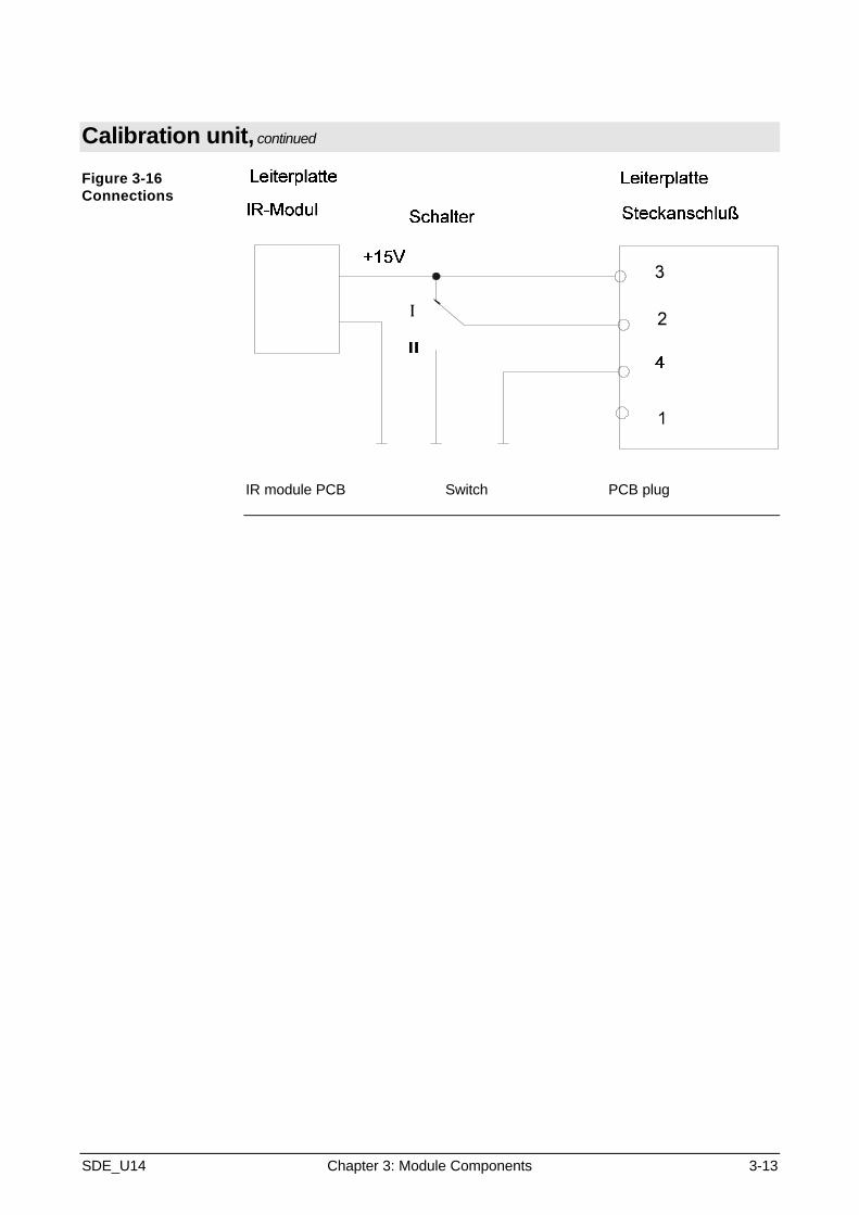
Figure 3-16Connections
IR module PCB Switch PCB plug
3-14 Chapter 3: Module Components SDE_U14
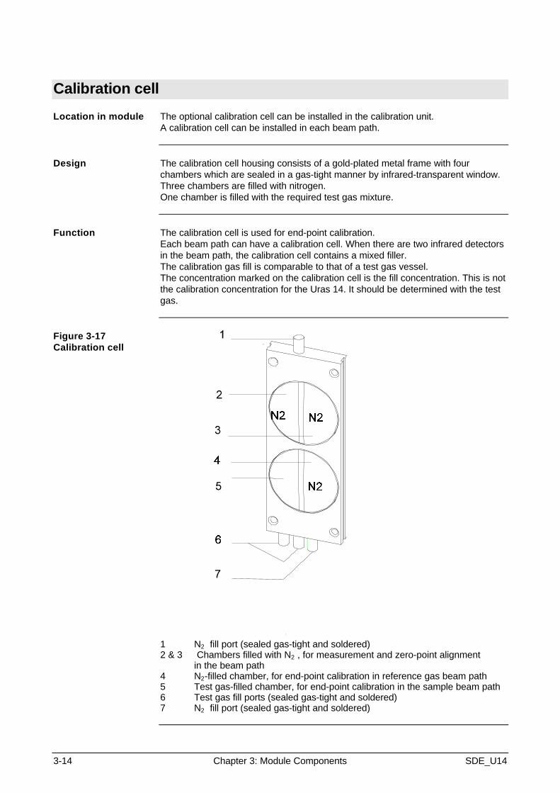
Calibration cell
Location in module The optional calibration cell can be installed in the calibration unit.A calibration cell can be installed in each beam path.
Design The calibration cell housing consists of a gold-plated metal frame with fourchambers which are sealed in a gas-tight manner by infrared-transparent window.Three chambers are filled with nitrogen.One chamber is filled with the required test gas mixture.
Function The calibration cell is used for end-point calibration.Each beam path can have a calibration cell. When there are two infrared detectorsin the beam path, the calibration cell contains a mixed filler.The calibration gas fill is comparable to that of a test gas vessel.The concentration marked on the calibration cell is the fill concentration. This is notthe calibration concentration for the Uras 14. It should be determined with the testgas.
Figure 3-17Calibration cell
1 N2 fill port (sealed gas-tight and soldered)2 & 3 Chambers filled with N2 , for measurement and zero-point alignment
in the beam path4 N2-filled chamber, for end-point calibration in reference gas beam path5 Test gas-filled chamber, for end-point calibration in the sample beam path6 Test gas fill ports (sealed gas-tight and soldered)7 N2 fill port (sealed gas-tight and soldered)
SDE_U14 Chapter 3: Module Components 3-15
Infrared detector
Location in module The infrared detector is placed at the end of the sample cell.Depending on the application, there can be 1-4 detectors. Up to 2 detectors can beinstalled per beam path.
Design The infrared detector consists of the following parts:• Optopneumatic part, consisting of 2 consecutively connected chambers;
these are separated by infrared-transparent windows.The chambers are filled with the gas appropriate for the sample componentinvolved.The emission-free area contains the diaphragm capacitor made up of a gas-tight,metal diaphragm installed between the two chamber portions and a fixedcounterelectrode. Both parts are connected to the preamplifier via gas-tightpassages.
• The preamplifier is an integral part of the detector.The preamplifier incorporates a temperature sensor for temperaturecompensation.
Function The beam reaching the detector is absorbed in the region of the fill gas absorptionline and by means of molecular collision is momentarily changed into a pressurereflecting the heat energy. This pressure change is detected by the diaphragmcapacitor.Via a high-impedance circuit, the 150-volt power supplied now generates acorresponding mV-range DC voltage.Primary absorption of the emission occurs in the front chamber (positivedisplacement). The flank-emphasized light emission portion of the rotation line,which leads to cross sensitivity in case of interfering gas component overlap, actson the rear chamber. Due to the greater depth of the rear chamber this interferingemission is extensively absorbed so that here there is a pressure increase whichcounters the pressure in the front chamber. This results in some suppression ofcross-sensitivity effects.The temperature sensor determines the ambient temperature of the opticalcomponents and thus is part of the measurement signal temperaturecompensation mechanism. Only the sensor of the first infrared detector is involved.
Types All infrared detectors are mechanically identical. The application determines the fill.The detectors are suitable for all measurement ranges permitted according to thedata sheet.Measurement components:CO, NO, SO2, N2O, Frigen/R12, H2O, SF6, CS2, NH3
CH4, C2H2, C2H4, C2H6, C3H6, C3H8, C4H10, C6H6, C6H14
CO2 with 10% fill for small measurement rangesCO2 with 100% fill for large measurement ranges
Continued on next page
3-16 Chapter 3: Module Components SDE_U14
Infrared detector, continued
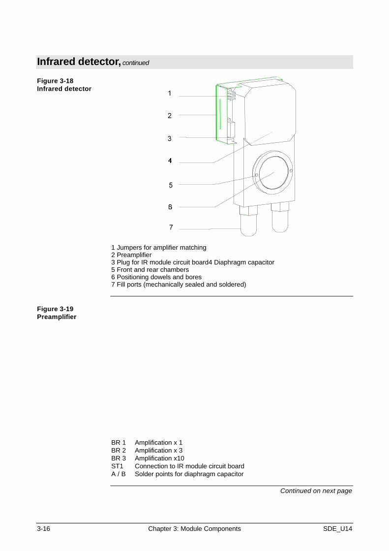
Figure 3-18Infrared detector
1 Jumpers for amplifier matching2 Preamplifier3 Plug for IR module circuit board4 Diaphragm capacitor5 Front and rear chambers6 Positioning dowels and bores7 Fill ports (mechanically sealed and soldered)
Figure 3-19Preamplifier
BR 1 Amplification x 1BR 2 Amplification x 3BR 3 Amplification x10ST1 Connection to IR module circuit boardA / B Solder points for diaphragm capacitor
Continued on next page
SDE_U14 Chapter 3: Module Components 3-17
Infrared detector, continued
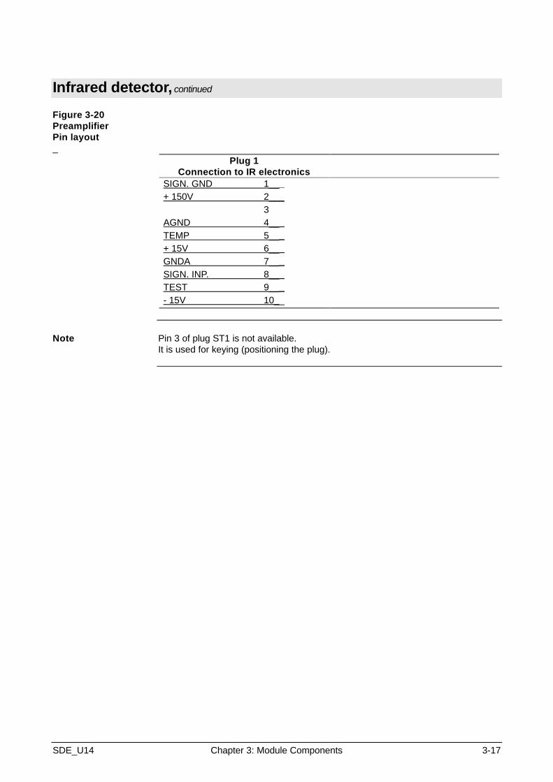
Figure 3-20PreamplifierPin layout_
Plug 1Connection to IR electronics
SIGN. GND 1___+ 150V 2___
3AGND 4___TEMP 5___+ 15V 6___GNDA 7___SIGN. INP. 8___TEST 9___- 15V 10__
Note Pin 3 of plug ST1 is not available.It is used for keying (positioning the plug).
3-18 Chapter 3: Module Components SDE_U14
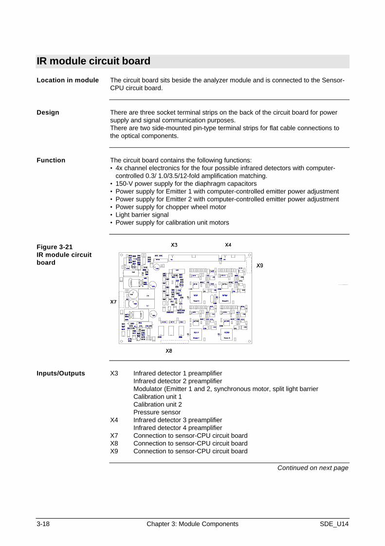
IR module circuit board
Location in module The circuit board sits beside the analyzer module and is connected to the Sensor-CPU circuit board.
Design There are three socket terminal strips on the back of the circuit board for powersupply and signal communication purposes.There are two side-mounted pin-type terminal strips for flat cable connections tothe optical components.
Function The circuit board contains the following functions:• 4x channel electronics for the four possible infrared detectors with computer-
controlled 0.3/ 1.0/3.5/12-fold amplification matching.• 150-V power supply for the diaphragm capacitors• Power supply for Emitter 1 with computer-controlled emitter power adjustment• Power supply for Emitter 2 with computer-controlled emitter power adjustment• Power supply for chopper wheel motor• Light barrier signal• Power supply for calibration unit motors
Figure 3-21IR module circuitboard
Inputs/Outputs X3 Infrared detector 1 preamplifierInfrared detector 2 preamplifierModulator (Emitter 1 and 2, synchronous motor, split light barrierCalibration unit 1Calibration unit 2Pressure sensor
X4 Infrared detector 3 preamplifierInfrared detector 4 preamplifier
X7 Connection to sensor-CPU circuit boardX8 Connection to sensor-CPU circuit boardX9 Connection to sensor-CPU circuit board
Continued on next page

SDE_U14 Chapter 3: Module Components 3-19
IR module circuit board, continued
Figure 3-22.1Pin layoutIR module circuitboard
Plug X 3 Plug X3S1 + 1___ CCVORH 1 39__S1 + 2___ CC 1 40__F1 + 3___ + 15V 41__S1 - 4___ 42__F1 - 5___ 43__S2 - 6___ 44__S2 + 7___ CCVORH 2 45__F2 - 8___ CC 2 46__MOTOR 1 9___ + 15V 47__F2 + 10__ 48__MOTOR 2 11__ 49__
12__ 50__+ 5V 13__L_SCHR 14__+ 15V 15__- 15V 16__
17__BARO 1 18__
19__+ 150V 20__
21__ 22__LN335 - 1 23__+ 15V 24__
25__VV 1 26__VV-Test 27__- 15V 28__
29__+ 150V 30__
31__ 32__
LM 335-2(nc) 33__+ 15V 34__
35__VV 2 36__VV-TEST 37__- 15V 38__
Continued on next page
3-20 Chapter 3: Module Components SDE_U14
IR module circuit board, continued
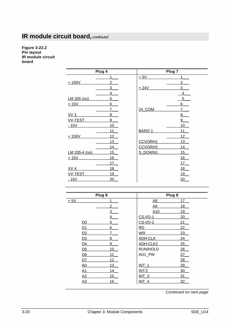
Figure 3-22.2Pin layoutIR module circuitboard
Plug 4 Plug 7 1___ + 5V 1___
+ 150V 2___ 2___ 3___ + 24V 3___ 4___ __4___
LM 335 (no) 5___ __5___+ 15V 6___ 6___
7___ 24_COM 7___VV 3 8___ 8___VV-TEST 9___ 9___- 15V 10__ 10__
11__ BARO 1 11__+ 150V 12__ 12__
13__ CCVORH1 13__ 14__ CCVORH2 14__
LM 335-4 (no) 15__ S_DOWN1 15__+ 15V 16__ 16__
17__ 17__VV 4 18__ 18__VV-TEST 19__ 19__- 15V 20__ 20__
Plug 8 Plug 8+ 5V 1___ A8 17__
2___ A9 18__3___ A10 19__4___ CS-I/O-1 20__
D0 5___ CS-I/O-2 21__D1 6___ RD 22__D2 7___ WR 23__D3 8___ ADH-CLK 24__D4 9___ ADH-CLK2 25__D5 10__ RUN/HOLD 26__D6 11__ AD1_PW 27__D7 12__ 28__A0 13__ INT_1 29__A1 14__ INT:2 30__A2 15__ INT_3 31__A3 16__ INT_4 32__
Continued on next page

SDE_U14 Chapter 3: Module Components 3-21
IR module circuit board, continued
Figure 3-22.3Pin layoutIR module circuitboard
Plug 9+ 15V 1___- 15V 2___
3___NTC 1 4___LM335-1 5___(NTC) 6___RESET 7___ICLK 8___IDAT 9___
10__TFS_77 11__RFS_77 12__DIN_77 13__DOUT_77 14__SCLK_77 15__DRDY_77 16__SYNC_77 17__A=/CS_77 18__
19__20__
3-22 Chapter 3: Module Components SDE_U14
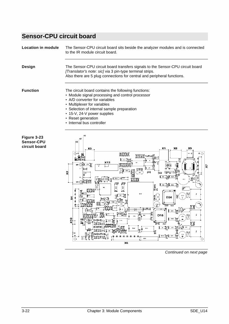
Sensor-CPU circuit board
Location in module The Sensor-CPU circuit board sits beside the analyzer modules and is connectedto the IR module circuit board.
Design The Sensor-CPU circuit board transfers signals to the Sensor-CPU circuit board[Translator's note: sic] via 3 pin-type terminal strips.Also there are 5 plug connections for central and peripheral functions.
Function The circuit board contains the following functions:• Module signal processing and control processor• A/D converter for variables• Multiplexer for variables• Selection of internal sample preparation• 15-V, 24-V power supplies• Reset generation• Internal bus controller
Figure 3-23Sensor-CPUcircuit board
Continued on next page
SDE_U14 Chapter 3: Module Components 3-23
Sensor-CPU circuit board, continued
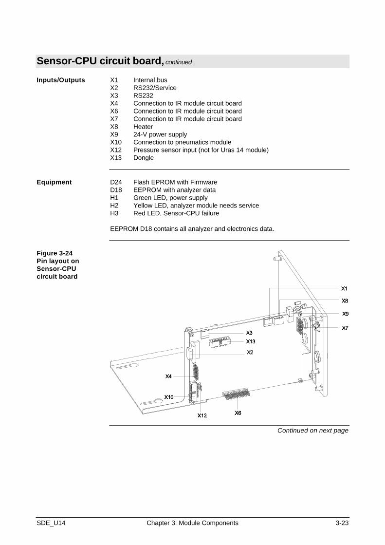
Inputs/Outputs X1 Internal busX2 RS232/ServiceX3 RS232X4 Connection to IR module circuit boardX6 Connection to IR module circuit boardX7 Connection to IR module circuit boardX8 HeaterX9 24-V power supplyX10 Connection to pneumatics moduleX12 Pressure sensor input (not for Uras 14 module)X13 Dongle
Equipment D24 Flash EPROM with FirmwareD18 EEPROM with analyzer dataH1 Green LED, power supplyH2 Yellow LED, analyzer module needs serviceH3 Red LED, Sensor-CPU failure
EEPROM D18 contains all analyzer and electronics data.
Figure 3-24Pin layout onSensor-CPUcircuit board
Continued on next page

3-24 Chapter 3: Module Components SDE_U14
Sensor-CPU circuit board, continued
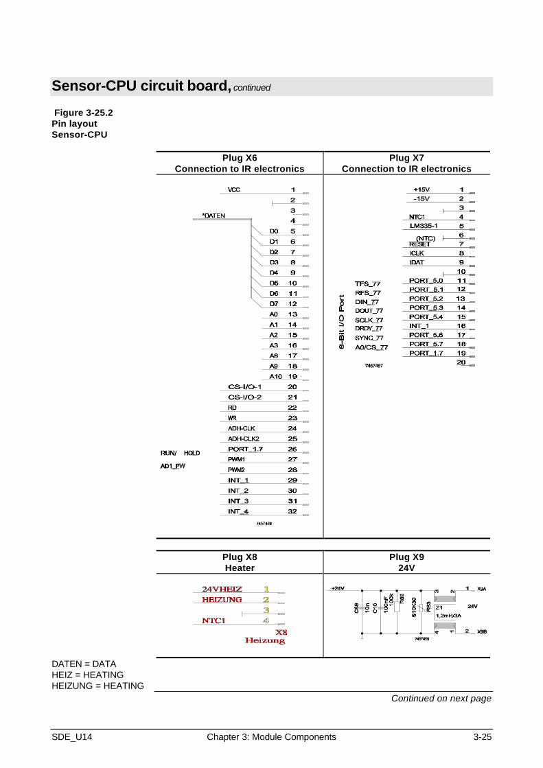
Figure 3-25.1Pin layoutSensor-CPU
Plug X1Internal bus
Socket X2RS232 Service
Plug X3RS232
Plug X4Connection to IR electronics
Continued on next page
SDE_U14 Chapter 3: Module Components 3-25
Sensor-CPU circuit board, continued
Figure 3-25.2Pin layoutSensor-CPU
Plug X6Connection to IR electronics
Plug X7Connection to IR electronics
Plug X8Heater
Plug X924V
DATEN = DATAHEIZ = HEATINGHEIZUNG = HEATING
Continued on next page

3-26 Chapter 3: Module Components SDE_U14
Sensor-CPU circuit board, continued
Figure 3-25.3Pin layoutSensor-CPU
Plug X10Pneumatics module
Plug X12Flow rate sensor
not applicable to Uras 14

SDE_U14 Chapter 3: Module Components 3-27
Pressure sensor circuit board
Location in module The pressure sensor is mounted on the analyzer module base plate.
Design The pressure sensor is fastened to a circuit board with the appropriate circuitry.The circuit board is plug-connected to the IR module circuit board.
Function The pressure sensor measures the pressure in the sample cell.This signal is used for pressure correction of the measurement signal.Optionally the pressure sensor can be connected to measure external pressure viaa separate hose line.Specifications:• Absolute pressure sensor• Working range 700-1300 mbar• Offset calibration required
Figure 3-26Pressure sensorcircuit board
Inputs/Outputs X2 Connection to IR module circuit boardA Gas input (pressure in the sample cell)
Figure 3-27Pin layout
3-28 Chapter 3: Module Components SDE_U14
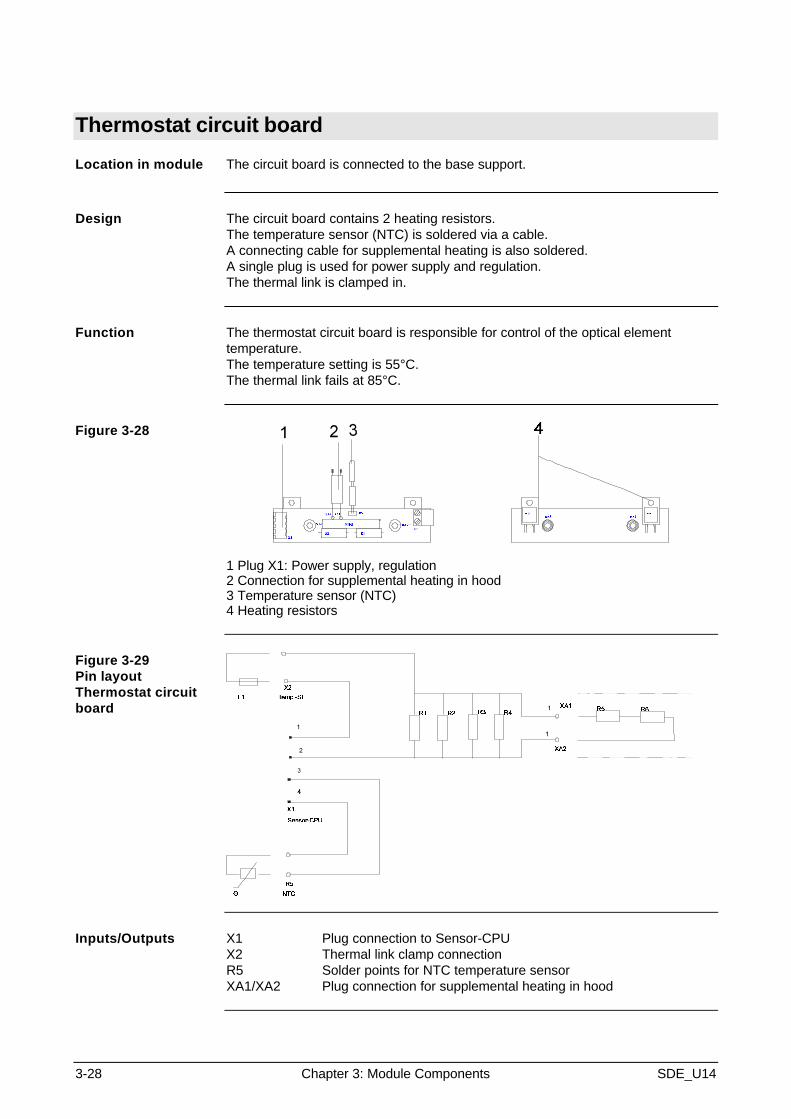
Thermostat circuit board
Location in module The circuit board is connected to the base support.
Design The circuit board contains 2 heating resistors.The temperature sensor (NTC) is soldered via a cable.A connecting cable for supplemental heating is also soldered.A single plug is used for power supply and regulation.The thermal link is clamped in.
Function The thermostat circuit board is responsible for control of the optical elementtemperature.The temperature setting is 55°C.The thermal link fails at 85°C.
Figure 3-28
1 Plug X1: Power supply, regulation2 Connection for supplemental heating in hood3 Temperature sensor (NTC)4 Heating resistors
Figure 3-29Pin layoutThermostat circuitboard
Inputs/Outputs X1 Plug connection to Sensor-CPUX2 Thermal link clamp connectionR5 Solder points for NTC temperature sensorXA1/XA2 Plug connection for supplemental heating in hood

SDE_U14 Chapter 3: Module Components 3-29
Hood with supplemental heater
Location in module This hood covers the optical components.
Design The hood consists of a U-shaped piece of sheet metal with a heating element fittedon each of the side walls.
Function The heated hood works with the base support heating system to control thetemperature of all optical elements. It is plug-connected in parallel with thethermostat circuit board.
Figure 3-30Hood with heater

3-30 Chapter 3: Module Components SDE_U14
Connecting cable
Location in module Connection between IR module circuit board and optical components.
Figure 3-31Connection 1
Figure 3-32Connection 2
Continued on next page

SDE_U14 Chapter 3: Module Components 3-31
Connecting cable, continued
Figure 3-33Pin layoutConnecting cable 1
Strahler=Emitter; VV = Preamplifier; Kanal = Channel; Kalibrierküvette=Calibration cell;IR-Elektronik = IR electronics
Continued on next page

3-32 Chapter 3: Module Components SDE_U14
Connecting cable, continued
Figure 3-34Pin layoutConnecting cable 2
Kanal = ChannelIR-Elektronik = IR electronics
Continued on next page

SDE_U14 Chapter 3: Module Components 3-33
Connecting cable, continued
Figure 3-35Connector position
IR-Modul = IR moduleStr = EmitterStrahler = EmitterBaro-Sensor = Pressure sensor
SDE_U14 Chapter 4: Troubleshooting 4-1
Chapter 4: Troubleshooting
Overview
Introduction This chapter contains information on troubleshooting and repairing the analyzermodule.
Chapter contents In this chapter you will find the following information:
Subject See pageDisplay error messagesDoes not operateUnreliable/wrong measurementsOutput errorInterface problemsOther errors
Being prepared
SDE_U14 Chapter 5: Testing 5-1
Chapter 5: Testing
Overview
Introduction This chapter describes procedures for testing the primary measurement andinfluence values on the analyzer module as well as testing of components.Special accessories will be described where necessary.
Chapter contents In this chapter you will find the following information:
Subject See pageSeal integrity 5-2Flow RateMeasurement signalIR module circuit boardSensor-CPU circuit boardEmitter 5-7ModulatorSample Cell 5-9Calibration unitCalibration cellInfrared detectorPressure sensorTemperature regulation 5-14
Some portions are still being prepared
5-2 Chapter 5: Testing SDE_U14
Checking Gas Path Seal Integrity
Accessories Pressure leak tester
Test method Pressure drop method:• Test pressure p = 50 mbar• Test time t = 180 sec• Pressure drop< 5 mbar
Procedure
Step Action1 Verify hose routing per hose connection diagram.2 Close sample gas outlet.3 Connect the pressure leak tester to the sample gas inlet.

SDE_U14 Chapter 5: Testing 5-3
Flow Rate
Being prepared

5-4 Chapter 5: Testing SDE_U14
Measurement signal
Being prepared
SDE_U14 Chapter 5: Testing 5-5
IR module circuit board
Being prepared
5-6 Chapter 5: Testing SDE_U14
Sensor-CPU circuit board
Being prepared
SDE_U14 Chapter 5: Testing 5-7
Emitter
Accessories Multimeter
Test method Voltage/resistance measurements• Cold resistance: 13 ± 0.5 Ω• Impressed voltage: 5.6 ± 0.5 V 2.2 W emitter output
7.45 ± 0.5 V 3.8 W emitter output 9.5 ± 0.5 V 6.8 W emitter output
Procedure
Step Action1 Voltage test:
• Emitter voltage can be measured at the emitter insert electricalleads.Note: The filament will light visibly at voltages between 7.45 and 9.5V.
2 Resistance test:• Loosen the emitter circuit board connections.• Measure cold resistance at the emitter leads.
5-8 Chapter 5: Testing SDE_U14
Modulator
Being prepared

SDE_U14 Chapter 5: Testing 5-9
Sample cell
Accessories Cleaners as necessary
Test method Visual check
Procedure
Step Action1 Remove the sample cell.2 Visual check;
• The windows should be unobstructed and free of coatings.• The gold-plated interior surfaces should have the typical gleam and
be free of any shading.3 Cleaning:
• Rinse (agitate) with distilled water; if necessary, loosen contaminantswith a small amount of detergent.
• Rinse with distilled water.• Dry with nitrogen (if possible, warmed to approx. 60°C).
5-10 Chapter 5: Testing SDE_U14
Calibration unit
Being prepared

SDE_U14 Chapter 5: Testing 5-11
Calibration cell
Being prepared
5-12 Chapter 5: Testing SDE_U14
Infrared detector
Being prepared

SDE_U14 Chapter 5: Testing 5-13
Pressure sensor
Being prepared

5-14 Chapter 5: Testing SDE_U14
Temperature regulation
Accessories Multimeter
Test method Voltage/resistance measurements• Power supply voltage 24 V• Heat resistors Base support: approx. 12.5 Ω
Hood: approx. 50 Ω• Temperature sensor (NTC) approx. 8 kΩ• Thermal link Check continuity
Procedure
Step Action1 Remove the connecting cable from the board (plug X8 on Sensor-CPU
PCB).2 Remove the electrical connection from the hood.3 Measure resistance at the appropriate connectors.
SDE_U14 Chapter 6: Component Interchange 6-1
Chapter 6: Component Interchange
Overview
Introduction This chapter contains the steps and procedures to be followed when interchangingcomponents.
In order to remove and install components safely and correctly, read and follow allthe instructions and warnings in this chapter.
Caution!The tasks described in this chapter require special training and undercertain conditions involve working on the analyzer while it is open andpowered up. For this reason, these tasks should only be carried out byspecially trained and qualified persons.
Chapter contents You will find the following information in this chapter:
Subject See pageSummary 5-2Remove/install Uras 14 analyzer module 5-3Change emitter insert 5-5Change modulator 5-6Change sample cell 5-7Change calibration cell and calibration unit 5-9Change infrared detector 5-10Change IR module and Sensor-CPU circuit boards 5-11Change thermal link 5-12
6-2 Chapter 6: Component Interchange SDE_U14
Summary
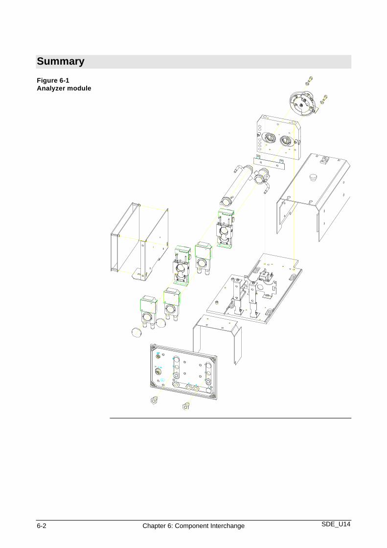
Figure 6-1Analyzer module
SDE_U14 Chapter 6: Component Interchange 6-3
Remove/install Uras 14 analyzer module
Module removal To remove the module, proceed as follows:
Step Action1 Turn off the analyzer power supply.2 Shut off the gas supply (sample gas and, if applicable, reference gas)
to the analyzer.3 Disconnect the gas lines from the analyzer module ports.4 Flush the analyzer module.5 Open the system housing.6 Remove the cables connecting the analyzer module to the central unit.7 Disconnect the hood cable.8 Remove 4 screws (1)9 Remove the hood.10 Remove the analyzer module mounting screws.
4 bolts on the gas connection plate (2).4 nuts on the base plate (3).
11 Remove the analyzer module from the housing
Module installation To install the module, proceed as follows
Step Action1 Place the analyzer module in the system housing.2 Secure the analyzer module with the four bolts and four nuts.3 Install the hood.4 Reconnect the cables.5 Close the system housing.6 Check the analyzer module seal integrity.7 Connect the gas lines to the analyzer module.8 Open the gas supply to the analyzer module.9 Turn on the analyzer system power supply
Continued on the following page

6-4 Chapter 6: Component Interchange SDE_U14
Remove/install Uras 14 analyzer module, continued
Figure 6-2Opening theanalyzer module
Figure 6-3Removing theanalyzer module
SDE_U14 Chapter 6: Component Interchange 6-5
Change emitter insert
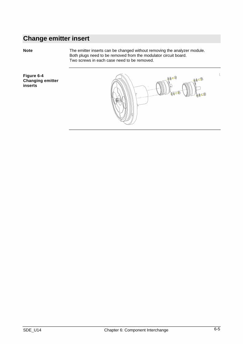
Note The emitter inserts can be changed without removing the analyzer module.Both plugs need to be removed from the modulator circuit board.Two screws in each case need to be removed.
Figure 6-4Changing emitterinserts

6-6 Chapter 6: Component Interchange SDE_U14
Change modulator
Note The modulator can be changed without removing the analyzer module.The connecting cable plug needs to be removed from the modulator circuit board.Remove three screws (1).
Figure 6-5Removing themodulator
Figure 6-6Disassembling themodulator
SDE_U14 Chapter 6: Component Interchange 6-7
Change sample cell
Removing/installingthe sample cell
To remove the sample cell, proceed as follows:
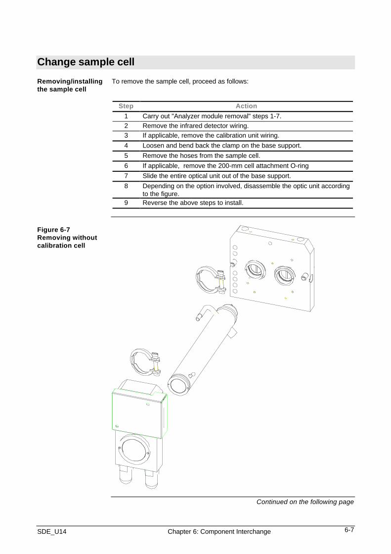
Step Action1 Carry out "Analyzer module removal" steps 1-7.2 Remove the infrared detector wiring.3 If applicable, remove the calibration unit wiring.4 Loosen and bend back the clamp on the base support.5 Remove the hoses from the sample cell.6 If applicable, remove the 200-mm cell attachment O-ring7 Slide the entire optical unit out of the base support.8 Depending on the option involved, disassemble the optic unit according
to the figure.9 Reverse the above steps to install.
Figure 6-7Removing withoutcalibration cell
Continued on the following page

6-8 Chapter 6: Component Interchange SDE_U14
Change sample cell, Continued
Figure 6-8Removing samplecellwith calibration unit
SDE_U14 Chapter 6: Component Interchange 6-9
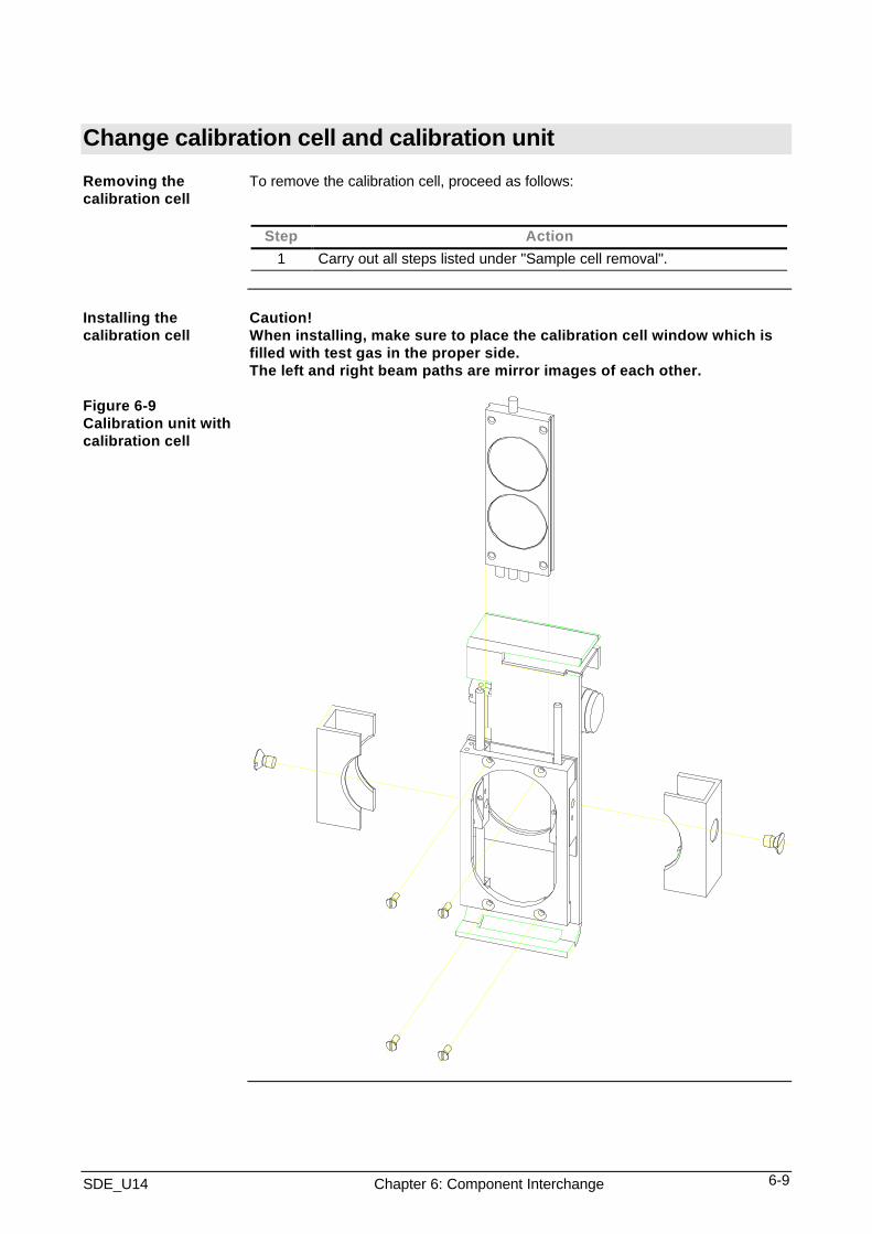
Change calibration cell and calibration unit
Removing thecalibration cell
To remove the calibration cell, proceed as follows:
Step Action1 Carry out all steps listed under "Sample cell removal".
Installing thecalibration cell
Caution!When installing, make sure to place the calibration cell window which isfilled with test gas in the proper side.The left and right beam paths are mirror images of each other.
Figure 6-9Calibration unit withcalibration cell

6-10 Chapter 6: Component Interchange SDE_U14
Change infrared detector
Removing/installingthe infrared detector
To remove the infrared detector, proceed as follows:
Step Action1 Carry out "Analyzer module removal" steps 1-7.2 Remove all wiring connected to the optical components.3 Loosen and bend back the clamp on the base support.4 Remove the hoses from the sample cell.5 If applicable, remove the 200-mm cell attachment O-ring6 Pull the entire optical unit out of the base support.7 Remove the infrared detector per Figure 5-8 and 5-10.8 Reverse the above steps to install
Make sure the proper end disk (bright or dark) is installed behind theinfrared detector.
Figure 6-10Removing theinfrared detector

SDE_U14 Chapter 6: Component Interchange 6-11
Change IR module and Sensor-CPU circuit boards
Removing the circuitboard
To remove the circuit boards, proceed as follows:
Step Action1 Turn off the analyzer power supply.2 Open the large door on the system housing.3 Remove all cable connections from the circuit boards.4 Loosen the two knurled nuts (RS1 and RS2) and remove the IR
module and Sensor-CPU board from the support.5 Remove the four attaching screws (1) and carefully remove the IR
module circuit board from the Sensor-CPU board connector.
Installing the circuitboard
Essentially the installation process is the reverse of the removal process.
Figure 6-11Analyzer moduleview
Caution!The Sensor-CPU circuit board contains the flash EPROM with the modulefirmware and the EEPROM with module-specific data.

6-12 Chapter 6: Component Interchange SDE_U14
Change thermal link
Removing thethermal link
To remove the thermal link, proceed as follows:
Step Action1 Turn off the analyzer power supply.2 Open the large door on the analyzer housing.3 Remove the hood.4 Remove the thermostat circuit board connector.5 Pull the thermal link (T) out of the base support.
Installing thethermal link
Essentially the installation process is the reverse of the removal process.
Figure 6-12Analyzer modulePartial view
SDE_U14 Chapter 7: Calibration 7-1
Chapter 7: Calibration
Overview
Introduction This chapter describes the basic calibration of the analyzer module and theancillary detectors.
Chapter contents In this chapter you will find the following information:
Subject See pageBasic calibration of the Uras 14 7-2Basic calibration of variables
Being prepared
SDE_U14 Chapter 8: Configuration 8-1
Chapter 8: Configuration
Overview
Being prepared
SDE_U14 Chapter 9: Spare Parts List 9-1
Chapter 9: Spare parts list
Overview
Introduction This chapter contains the spare parts list for the Uras 14 analyzer module.It identifies the spare parts with a part number, description and additionalinformation.
Chapter contents You will find the following information in this chapter:
Subject See pageNotes 8-2Spare parts list 8-3
9-2 Chapter 9: Spare Parts List SDE_U14
Notes
being prepared
SDE_U14 Chapter 9: Spare Parts List 9-3
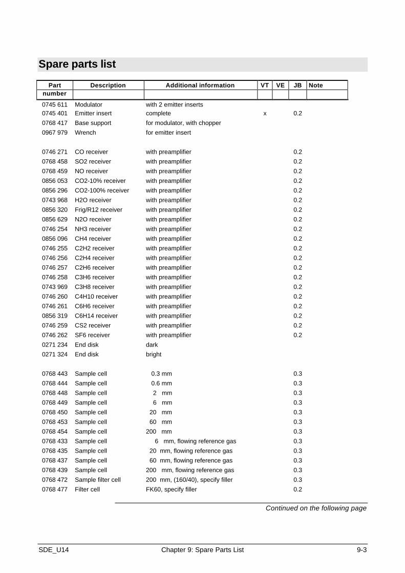
Spare parts list
Partnumber
Description Additional information VT VE JB Note
0745 611 Modulator with 2 emitter inserts0745 401 Emitter insert complete x 0.20768 417 Base support for modulator, with chopper0967 979 Wrench for emitter insert
0746 271 CO receiver with preamplifier 0.20768 458 SO2 receiver with preamplifier 0.20768 459 NO receiver with preamplifier 0.20856 053 CO2-10% receiver with preamplifier 0.20856 296 CO2-100% receiver with preamplifier 0.20743 968 H2O receiver with preamplifier 0.20856 320 Frig/R12 receiver with preamplifier 0.20856 629 N2O receiver with preamplifier 0.20746 254 NH3 receiver with preamplifier 0.20856 096 CH4 receiver with preamplifier 0.20746 255 C2H2 receiver with preamplifier 0.20746 256 C2H4 receiver with preamplifier 0.20746 257 C2H6 receiver with preamplifier 0.20746 258 C3H6 receiver with preamplifier 0.20743 969 C3H8 receiver with preamplifier 0.20746 260 C4H10 receiver with preamplifier 0.20746 261 C6H6 receiver with preamplifier 0.20856 319 C6H14 receiver with preamplifier 0.20746 259 CS2 receiver with preamplifier 0.20746 262 SF6 receiver with preamplifier 0.20271 234 End disk dark0271 324 End disk bright
0768 443 Sample cell 0.3 mm 0.30768 444 Sample cell 0.6 mm 0.30768 448 Sample cell 2 mm 0.30768 449 Sample cell 6 mm 0.30768 450 Sample cell 20 mm 0.30768 453 Sample cell 60 mm 0.30768 454 Sample cell 200 mm 0.30768 433 Sample cell 6 mm, flowing reference gas 0.30768 435 Sample cell 20 mm, flowing reference gas 0.30768 437 Sample cell 60 mm, flowing reference gas 0.30768 439 Sample cell 200 mm, flowing reference gas 0.30768 472 Sample filter cell 200 mm, (160/40), specify filler 0.30768 477 Filter cell FK60, specify filler 0.2
Continued on the following page
9-4 Chapter 9: Spare Parts List SDE_U14
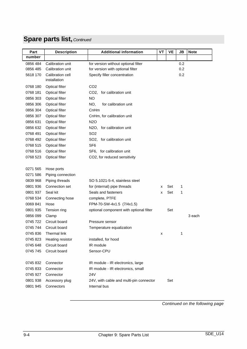
Spare parts list, Continued
Partnumber
Description Additional information VT VE JB Note
0856 484 Calibration unit for version without optional filter 0.20856 485 Calibration unit for version with optional filter 0.25618 170 Calibration cell
installationSpecify filler concentration 0.2
0768 180 Optical filter CO20768 181 Optical filter CO2, for calibration unit0856 303 Optical filter NO0856 306 Optical filter NO, for calibration unit0856 304 Optical filter CnHm0856 307 Optical filter CnHm, for calibration unit0856 631 Optical filter N2O0856 632 Optical filter N2O, for calibration unit0768 491 Optical filter SO20768 492 Optical filter SO2, for calibration unit0768 515 Optical filter SF60768 516 Optical filter SF6, for calibration unit0768 523 Optical filter CO2, for reduced sensitivity
0271 565 Hose ports0271 586 Piping connection0839 968 Piping threads SO 5.1021-5-4, stainless steel0801 936 Connection set for (internal) pipe threads x Set 10801 937 Seal kit Seals and fasteners x Set 10768 534 Connecting hose complete, PTFE0069 841 Hose FPM-70-SW-4x1.5 (7/4x1.5)0801 935 Tension ring optional component with optional filter Set0856 099 Clamp 3 each0745 722 Circuit board Pressure sensor0745 744 Circuit board Temperature equalization0745 836 Thermal link x 10745 823 Heating resistor installed, for hood0745 648 Circuit board IR module0745 745 Circuit board Sensor-CPU
0745 832 Connector IR module - IR electronics, large0745 833 Connector IR module - IR electronics, small0745 927 Connector 24V0801 938 Accessory plug 24V, with cable and multi-pin connector Set0801 945 Connectors Internal bus
Continued on the following page
SDE_U14 Chapter 9: Spare Parts List 9-5
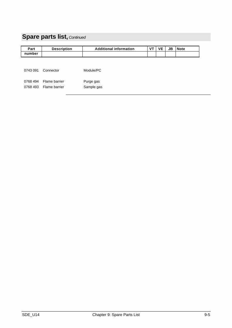
Spare parts list, Continued
Partnumber
Description Additional information VT VE JB Note
0743 091 Connector Module/PC
0768 494 Flame barrier Purge gas0768 493 Flame barrier Sample gas

Subject to technical changesPrinted in the Fed. Rep. of Germany
43/24-1005-0 EN 10.98
![Asset X Management of Toxic Gases (H2S and SO2) in Operations [2]](https://static.fdocuments.in/doc/165x107/577c7c7c1a28abe0549ac985/asset-x-management-of-toxic-gases-h2s-and-so2-in-operations-2.jpg)