Advance Line Following Sensor Bar - robotshop.com · ROBOT . HEAD to TOE Product User’s Manual...
35
Advance Line Following Sensor Bar LSA08 User’s Manual V1.0 September 2011 Information contained in this publication regarding device applications and the like is intended through suggestion only and may be superseded by updates. It is your responsibility to ensure that your application meets with your specifications. No representation or warranty is given and no liability is assumed by Cytron Technologies Incorporated with respect to the accuracy or use of such information or infringement of patents or other intellectual property rights arising from such use or otherwise. Use of Cytron Technologies’s products as critical components in life support systems is not authorized except with express written approval by Cytron Technologies. No licenses are conveyed, implicitly or otherwise, under any intellectual property rights.
Transcript of Advance Line Following Sensor Bar - robotshop.com · ROBOT . HEAD to TOE Product User’s Manual...

Advance Line Following Sensor Bar
LSA08
User’s Manual
V1.0
September 2011
Information contained in this publication regarding device applications and the like is intended through suggestion only and
may be superseded by updates. It is your responsibility to ensure that your application meets with your specifications. No
representation or warranty is given and no liability is assumed by Cytron Technologies Incorporated with respect to the
accuracy or use of such information or infringement of patents or other intellectual property rights arising from such use or
otherwise. Use of Cytron Technologies’s products as critical components in life support systems is not authorized except
with express written approval by Cytron Technologies. No licenses are conveyed, implicitly or otherwise, under any
intellectual property rights.

ROBOT . HEAD to TOE Product User’s Manual – LSA08
Index
1. Introduction and Overview 3
2. Packing List 4
3. Product Specification and Limitations 5
4. Board or Product Layout 8
5. Installation (hardware) 10
6. Getting Started 18
6.1 Output Port 25
6.1.1 PORT A – Analog and UART port 25
6.1.2 PORT B – Digital Output port 32
6.13 PORT C – External LCD 34
7. Warranty (6 months or 1 year) 35
Created by Cytron Technologies Sdn. Bhd. – All Rights Reserved
ROBOT . HEAD to TOE Product User’s Manual – LSA08
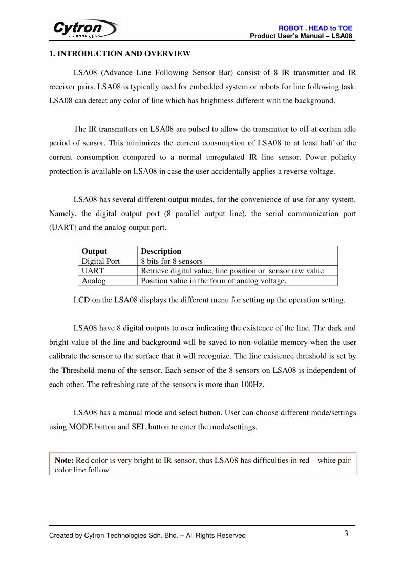
1. INTRODUCTION AND OVERVIEW
LSA08 (Advance Line Following Sensor Bar) consist of 8 IR transmitter and IR
receiver pairs. LSA08 is typically used for embedded system or robots for line following task.
LSA08 can detect any color of line which has brightness different with the background.
The IR transmitters on LSA08 are pulsed to allow the transmitter to off at certain idle
period of sensor. This minimizes the current consumption of LSA08 to at least half of the
current consumption compared to a normal unregulated IR line sensor. Power polarity
protection is available on LSA08 in case the user accidentally applies a reverse voltage.
LSA08 has several different output modes, for the convenience of use for any system.
Namely, the digital output port (8 parallel output line), the serial communication port
(UART) and the analog output port.
Output Description
Digital Port 8 bits for 8 sensors
UART Retrieve digital value, line position or sensor raw value
Analog Position value in the form of analog voltage.
LCD on the LSA08 displays the different menu for setting up the operation setting.
LSA08 have 8 digital outputs to user indicating the existence of the line. The dark and
bright value of the line and background will be saved to non-volatile memory when the user
calibrate the sensor to the surface that it will recognize. The line existence threshold is set by
the Threshold menu of the sensor. Each sensor of the 8 sensors on LSA08 is independent of
each other. The refreshing rate of the sensors is more than 100Hz.
LSA08 has a manual mode and select button. User can choose different mode/settings
using MODE button and SEL button to enter the mode/settings.
Created by Cytron Technologies Sdn. Bhd. – All Rights Reserved 3
Note: Red color is very bright to IR sensor, thus LSA08 has difficulties in red – white pair
color line follow.
ROBOT . HEAD to TOE Product User’s Manual – LSA08
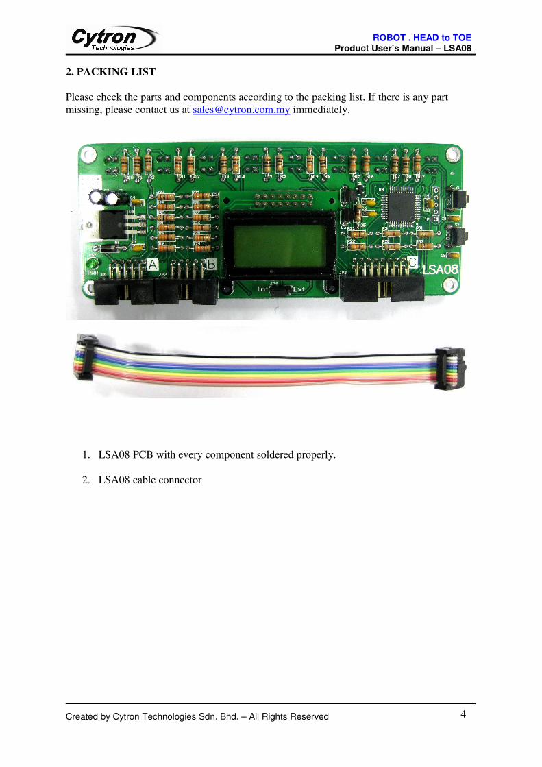
2. PACKING LIST
Please check the parts and components according to the packing list. If there is any part
missing, please contact us at [email protected] immediately.
1. LSA08 PCB with every component soldered properly.
2. LSA08 cable connector
Created by Cytron Technologies Sdn. Bhd. – All Rights Reserved 4

ROBOT . HEAD to TOE Product User’s Manual – LSA08
3. PRODUCT SPECIFICATION AND LIMITATIONS
Dimensions
Created by Cytron Technologies Sdn. Bhd. – All Rights Reserved 5
135
127.38
1518
46
.6654
.3

ROBOT . HEAD to TOE Product User’s Manual – LSA08
Electrical Specifications
Parameter Min Typical Maximum Unit
IR Emission (peak wavelength) 940 nm
Input signal, VIH 2 5 V
Input signal, VIL 0 0.8 V
Output Signal 5 V
Absolute Maximum Rating
Parameter Minimum Typical Maximum Unit
Operating voltage 7.5 12 V
Maximum Current (I/O signal pins) 20 mA
Sensing distance (from board) 1 3 5 cm
LSA08 Setting Menu:
Menu Description
LCD Contrast (LCD CON) Setting the contrast of LCD
Calibration (CALB)Calibrate LSA08 to the colour brightness of the line and
background
Line Mode (LINEMODE)
Setting LSA08 to be Dark On (for dark line and bright
background) or Light On (for bright line and dark
background)
Threshold (THRES)
Offset (OFFSET)
Maximum and minimum reading of sensor adjustment
to eliminate small fluctuation on the bar chart. (set to
zero if not used)
Junction Width (J WIDTH)Junction width, the number of bar chart on LCD for
LSA08 to treat it as a junction crossing.
UART Address (UART ADD) Unique UART address for the LSA08.
UART Baudrate
(BAUDRATE)
Setting the baudrate of the UART Communication
UART Mode (UARTMODE) Setting the UART output mode
LCD Backlight (LCD B/L) Setting the LCD backlight brightness
Exit (EXIT) Exit menu
Exit Menu shortcutPress and hold Mode button on any main menu will exit
the menu
Created by Cytron Technologies Sdn. Bhd. – All Rights Reserved 6
ROBOT . HEAD to TOE Product User’s Manual – LSA08
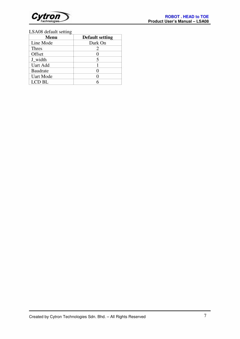
LSA08 default setting
Menu Default setting
Line Mode Dark On
Thres 2
Offset 0
J_width 5
Uart Add 1
Baudrate 0
Uart Mode 0
LCD BL 6
Created by Cytron Technologies Sdn. Bhd. – All Rights Reserved 7
ROBOT . HEAD to TOE Product User’s Manual – LSA08
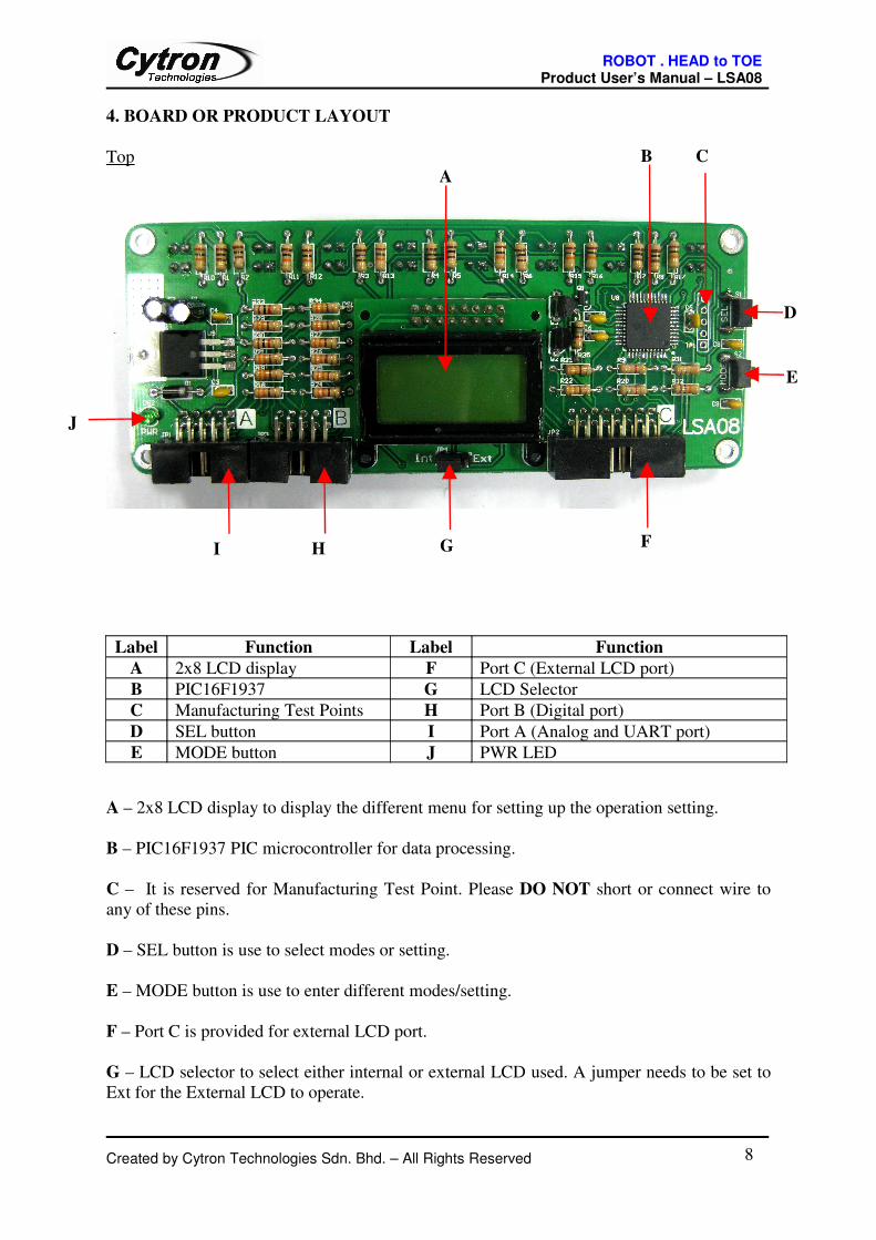
4. BOARD OR PRODUCT LAYOUT
Top
A – 2x8 LCD display to display the different menu for setting up the operation setting.
B – PIC16F1937 PIC microcontroller for data processing.
C – It is reserved for Manufacturing Test Point. Please DO NOT short or connect wire to
any of these pins.
D – SEL button is use to select modes or setting.
E – MODE button is use to enter different modes/setting.
F – Port C is provided for external LCD port.
G – LCD selector to select either internal or external LCD used. A jumper needs to be set to
Ext for the External LCD to operate.
Created by Cytron Technologies Sdn. Bhd. – All Rights Reserved 8
Label Function Label Function
A 2x8 LCD display F Port C (External LCD port)
B PIC16F1937 G LCD Selector
C Manufacturing Test Points H Port B (Digital port)
D SEL button I Port A (Analog and UART port)
E MODE button J PWR LED
F
A
B C
D
E
GHI
J
ROBOT . HEAD to TOE Product User’s Manual – LSA08
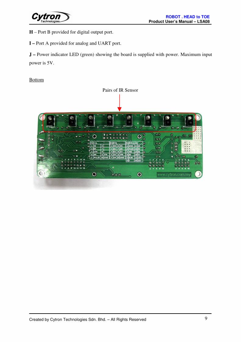
H – Port B provided for digital output port.
I – Port A provided for analog and UART port.
J – Power indicator LED (green) showing the board is supplied with power. Maximum input
power is 5V.
Bottom
Created by Cytron Technologies Sdn. Bhd. – All Rights Reserved 9
Pairs of IR Sensor
ROBOT . HEAD to TOE Product User’s Manual – LSA08
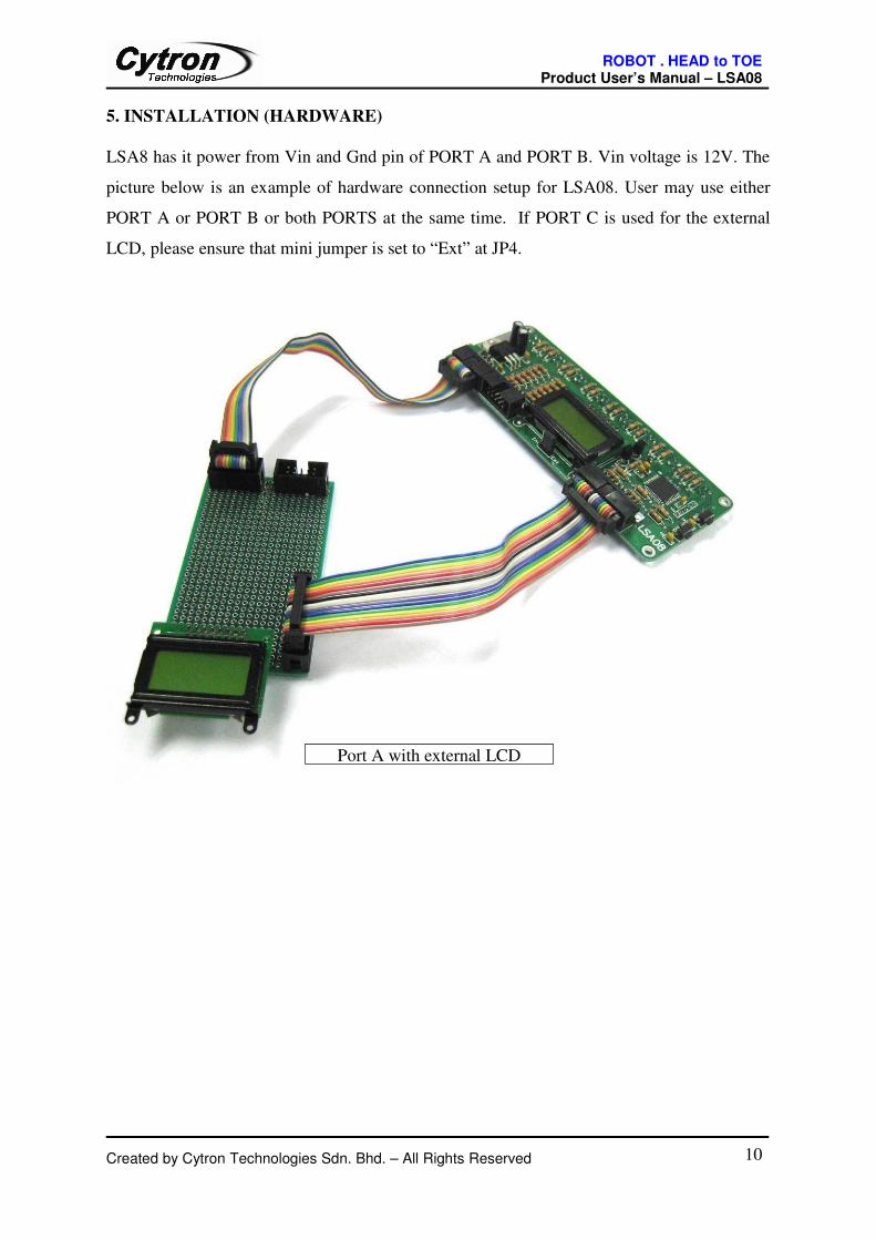
5. INSTALLATION (HARDWARE)
LSA8 has it power from Vin and Gnd pin of PORT A and PORT B. Vin voltage is 12V. The
picture below is an example of hardware connection setup for LSA08. User may use either
PORT A or PORT B or both PORTS at the same time. If PORT C is used for the external
LCD, please ensure that mini jumper is set to “Ext” at JP4.
Created by Cytron Technologies Sdn. Bhd. – All Rights Reserved 10
Port A with external LCD

ROBOT . HEAD to TOE Product User’s Manual – LSA08
Created by Cytron Technologies Sdn. Bhd. – All Rights Reserved 11
'Int' is set to use internal LCD
Port B with external LCD
ROBOT . HEAD to TOE Product User’s Manual – LSA08
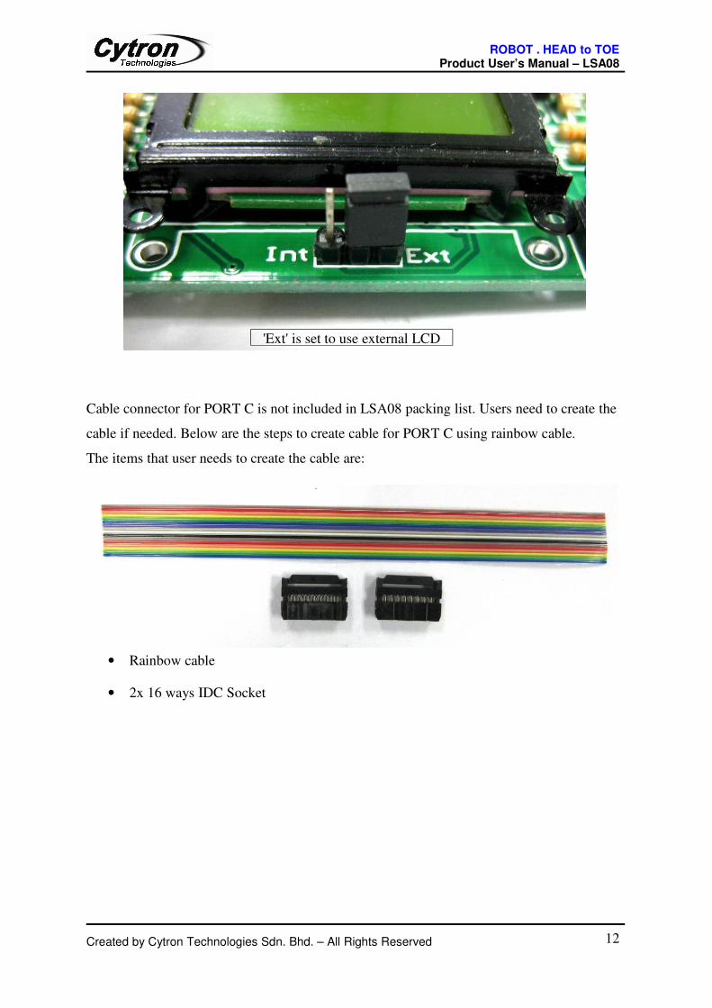
Cable connector for PORT C is not included in LSA08 packing list. Users need to create the
cable if needed. Below are the steps to create cable for PORT C using rainbow cable.
The items that user needs to create the cable are:
• Rainbow cable
• 2x 16 ways IDC Socket
Created by Cytron Technologies Sdn. Bhd. – All Rights Reserved 12
'Ext' is set to use external LCD

ROBOT . HEAD to TOE Product User’s Manual – LSA08
a) Remove the clip from IDC socket
b) Insert rainbow cable into IDC socket shown as figure below.
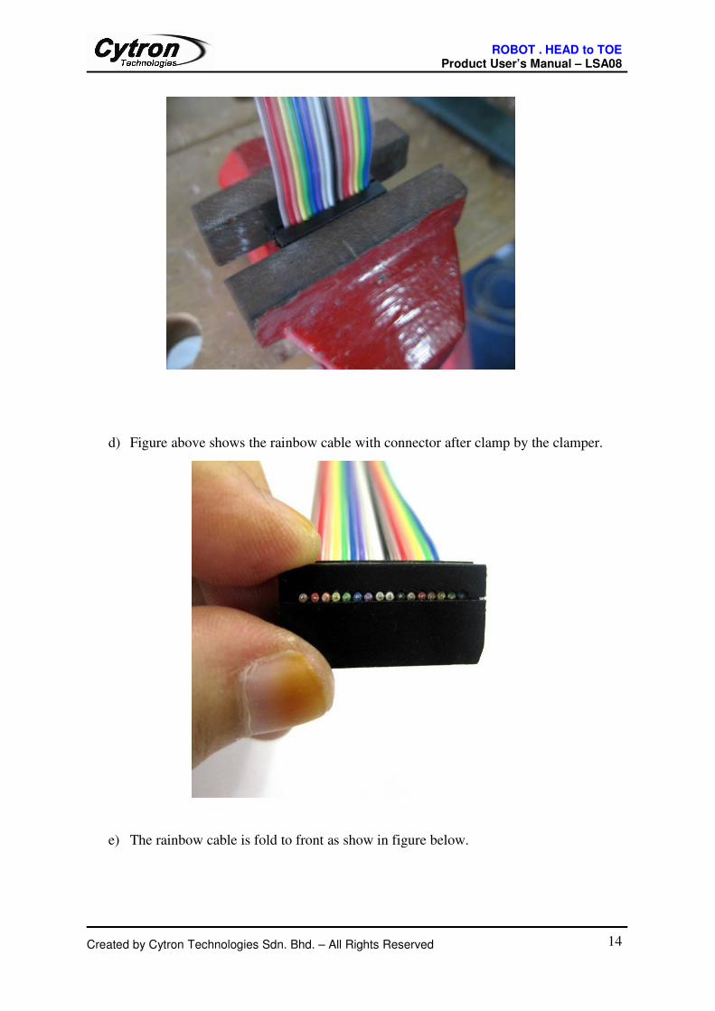
c) Clamp the rainbow cable to IDC socket using clamper.
Created by Cytron Technologies Sdn. Bhd. – All Rights Reserved 13
ROBOT . HEAD to TOE Product User’s Manual – LSA08
d) Figure above shows the rainbow cable with connector after clamp by the clamper.
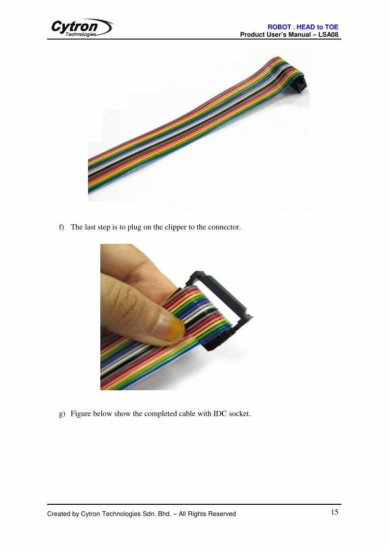
e) The rainbow cable is fold to front as show in figure below.
Created by Cytron Technologies Sdn. Bhd. – All Rights Reserved 14
ROBOT . HEAD to TOE Product User’s Manual – LSA08
f) The last step is to plug on the clipper to the connector.
g) Figure below show the completed cable with IDC socket.
Created by Cytron Technologies Sdn. Bhd. – All Rights Reserved 15

ROBOT . HEAD to TOE Product User’s Manual – LSA08
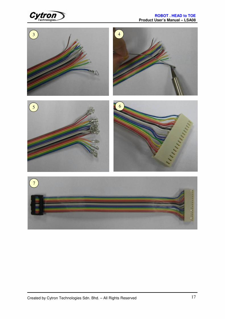
h) To connect LSA08 to main controller, user may use IDC socket for other end of
rainbow cable. It depends on the connector at the main controller side, modifications
can be done to the cable as needed.
Below are example steps for setting up LSA08 cable to connect to main controller using 2510
connector.
Created by Cytron Technologies Sdn. Bhd. – All Rights Reserved 16
1 2
ROBOT . HEAD to TOE Product User’s Manual – LSA08
Created by Cytron Technologies Sdn. Bhd. – All Rights Reserved 17
3 4
65
7

ROBOT . HEAD to TOE Product User’s Manual – LSA08
6. GETTING STARTED
LSA08 need to be calibrated to retrieve the dark and bright value of the surface that it
will do the line follow. Every of the IR sensor pairs need to be exposed to the dark and
bright surface for it to read the value and save it. LSA08 will save the value in EEPROM, it
will retrieve back the data from the EEPROM every time its switch on. Hence, only one time
calibration is needed for the same background and line unless the background and the line
changed, then recalibration is needed. To calibrate LSA08, go into menu setting using MODE
button. Choose CALB and enter the mode using SEL button. Calibration is started by
exposing the sensor to the bright surface and then to the dark surface of the line and
background in the allocated time. Restart the calibration if missed the timing. LSA08 will
save the brightest and darkest value in from the calibration process. User can calibrate by
simply swinging the sensors across the dark and bright surface of the line in order to expose
every sensor to the dark and bright surface. Calibration of every sensor is independent and
value of each sensor will be saved.
Example motions of calibration by crossing the sensor between the lines.
Created by Cytron Technologies Sdn. Bhd. – All Rights Reserved 18

ROBOT . HEAD to TOE Product User’s Manual – LSA08
Once power is supply to LSA08, LCD will display the line position detection and bar chart.
Line position detection is a value to shown which sensor is detect the line. The position on
LCD display is ranging from 0 to 70. When there is no line detected on LCD, the position
value will be shown as “****”. If sensor U0 detected a line, the line position reading shown
on LCD will be “0000”. Likewise if a line is detected on sensor U7 the position shown will
be “0070”. The position value varies in between linearly.
No line detected
Position 00 - U0 detect the dark line
Created by Cytron Technologies Sdn. Bhd. – All Rights Reserved 19
Line position
with no line
detected

ROBOT . HEAD to TOE Product User’s Manual – LSA08
Position 70 - U7 detect the dark line
If a line is at the middle of the LSA08( U3 and U4), the LCD display will show the position
as 35.
Position 35 – U3 and U4 detect the dark line
Created by Cytron Technologies Sdn. Bhd. – All Rights Reserved 20

ROBOT . HEAD to TOE Product User’s Manual – LSA08
Threshold is the value of bar chart on LCD for LSA08 to treat as a valid line. The threshold
value is from 0 to 7. If threshold is set to 7 for example, LSA08 will not detect the line if the
bar chart on LCD is less than 7 LCD also will only display “****” means no line detect.
For this example, the threshold is set to 2 and U1 is detect the dark line because the bar line is
more than 2.
Figure below shown LSA08 cannot detect the line because the threshold value is 7 and the
bar line display on LCD is less than 7.
Created by Cytron Technologies Sdn. Bhd. – All Rights Reserved 21

ROBOT . HEAD to TOE Product User’s Manual – LSA08
LCD on the LSA08 will displays the different menu for setting up the operation setting.
There are 10 setting for LSA08. Users may refer page 6 for menu setting description. For
example, user want to set LCD Backlight for LSA08. To enter menu setting:
1. Press MODE button once. It will bring user to 1st menu setting which is LCD CON.
2. Change the menu by more presses on Mode button until the desired menu appeared, for
example “LCD B/L”.
Created by Cytron Technologies Sdn. Bhd. – All Rights Reserved 22
ROBOT . HEAD to TOE Product User’s Manual – LSA08
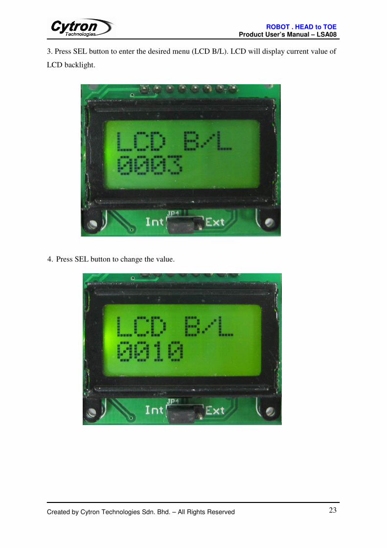
3. Press SEL button to enter the desired menu (LCD B/L). LCD will display current value of
LCD backlight.
4. Press SEL button to change the value.
Created by Cytron Technologies Sdn. Bhd. – All Rights Reserved 23

ROBOT . HEAD to TOE Product User’s Manual – LSA08
5. Press Mode button to return to menu selection
6. Press and Hold Mode button while in menu selection to exit
Created by Cytron Technologies Sdn. Bhd. – All Rights Reserved 24

ROBOT . HEAD to TOE Product User’s Manual – LSA08
6.1 Output Port
LSA08 has 2 output port (Port A and Port B) for 3 types of output mode. The outputs mode
for LSA08 are digital output (8 parallel output line), serial communication (UART) and
analog output. Port A is provided for UART and analog output mode and port B for digital
output mode. User may choose to use either this Port A or Port B or both. Vin and Gnd pin
are for the power of the LSA08. Both Port A and Port B has the pins, either of the port can
provide the power to LSA08.
6.1.1 PORT A - Analog and UART Port
Table below is pin defined for PORT A- Analog and UART port
Analog and UART Port (PORT A)
Pin Description Symbol
1 UART TX (Transmit) Tx
2 UART RX (Receive) Rx
3 UART Output Enable UEN
4 Analog Output AN
5 Junction Pulse JPULSE
6 Not used -
7 Not used -
8 Not used -
9 Vin VIN
10 GND GND
* Junction Pulse is for junction detection, pulse will be generated every time LSA08 crossing
a junction with minimum width determine by Junction Width setting.
Analog Output mode
Analog output pin represents the line position detected in the form of analog voltage. User
read the analog voltage on the pin using Analog to Digital converter to determine the position
of the line. The analog voltage value range from 0 Volt to 4.5 Volt which represents the line
position between sensor 0 to sensor 7. 5 Volt on the analog output pin represents no line
detected.
Created by Cytron Technologies Sdn. Bhd. – All Rights Reserved 25
ROBOT . HEAD to TOE Product User’s Manual – LSA08
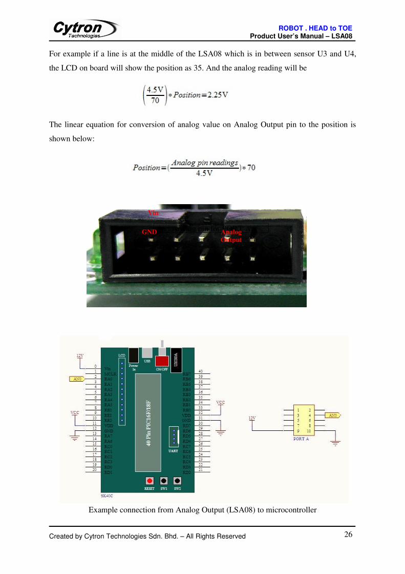
For example if a line is at the middle of the LSA08 which is in between sensor U3 and U4,
the LCD on board will show the position as 35. And the analog reading will be
The linear equation for conversion of analog value on Analog Output pin to the position is
shown below:
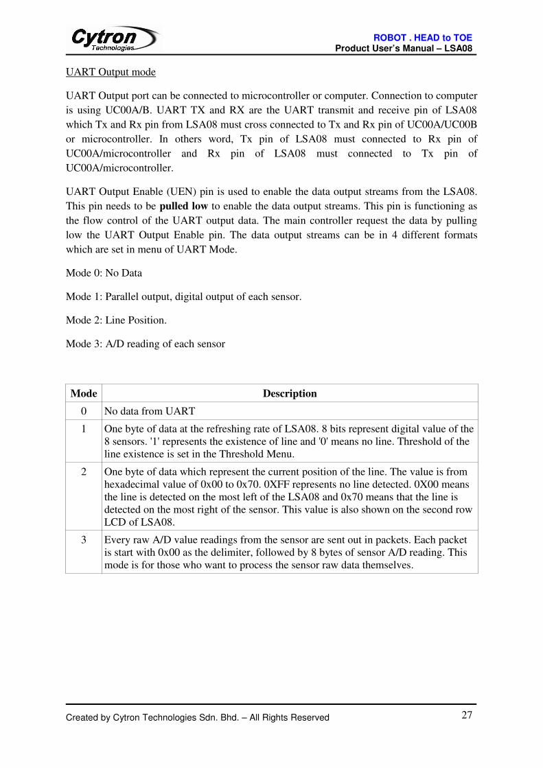
Example connection from Analog Output (LSA08) to microcontroller
Created by Cytron Technologies Sdn. Bhd. – All Rights Reserved 26
Vin
Analog pin for PORT AGND Analog
Output
ROBOT . HEAD to TOE Product User’s Manual – LSA08
UART Output mode
UART Output port can be connected to microcontroller or computer. Connection to computer
is using UC00A/B. UART TX and RX are the UART transmit and receive pin of LSA08
which Tx and Rx pin from LSA08 must cross connected to Tx and Rx pin of UC00A/UC00B
or microcontroller. In others word, Tx pin of LSA08 must connected to Rx pin of
UC00A/microcontroller and Rx pin of LSA08 must connected to Tx pin of
UC00A/microcontroller.
UART Output Enable (UEN) pin is used to enable the data output streams from the LSA08.
This pin needs to be pulled low to enable the data output streams. This pin is functioning as
the flow control of the UART output data. The main controller request the data by pulling
low the UART Output Enable pin. The data output streams can be in 4 different formats
which are set in menu of UART Mode.
Mode 0: No Data
Mode 1: Parallel output, digital output of each sensor.
Mode 2: Line Position.
Mode 3: A/D reading of each sensor
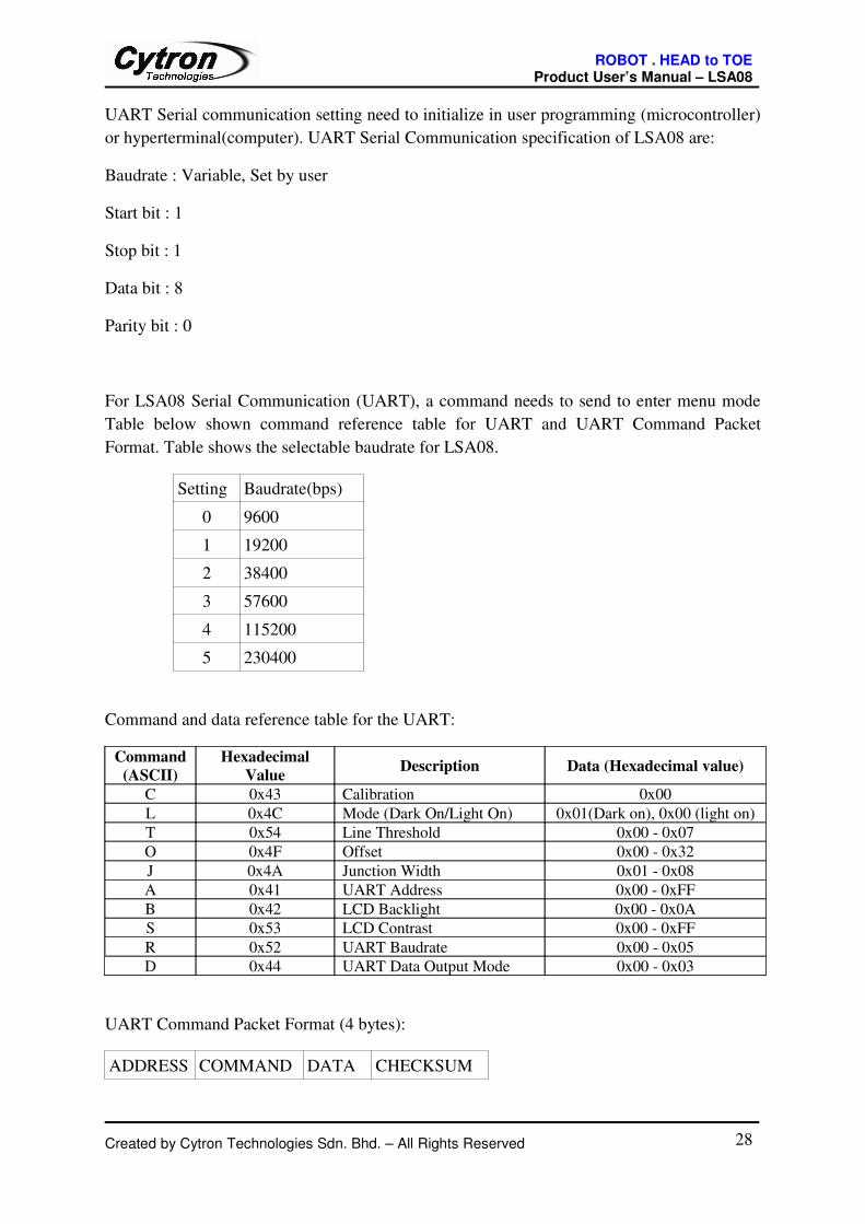
Mode Description
0 No data from UART
1 One byte of data at the refreshing rate of LSA08. 8 bits represent digital value of the
8 sensors. '1' represents the existence of line and '0' means no line. Threshold of the
line existence is set in the Threshold Menu.
2 One byte of data which represent the current position of the line. The value is from
hexadecimal value of 0x00 to 0x70. 0XFF represents no line detected. 0X00 means
the line is detected on the most left of the LSA08 and 0x70 means that the line is
detected on the most right of the sensor. This value is also shown on the second row
LCD of LSA08.
3 Every raw A/D value readings from the sensor are sent out in packets. Each packet
is start with 0x00 as the delimiter, followed by 8 bytes of sensor A/D reading. This
mode is for those who want to process the sensor raw data themselves.
Created by Cytron Technologies Sdn. Bhd. – All Rights Reserved 27
ROBOT . HEAD to TOE Product User’s Manual – LSA08
UART Serial communication setting need to initialize in user programming (microcontroller)
or hyperterminal(computer). UART Serial Communication specification of LSA08 are:
Baudrate : Variable, Set by user
Start bit : 1
Stop bit : 1
Data bit : 8
Parity bit : 0
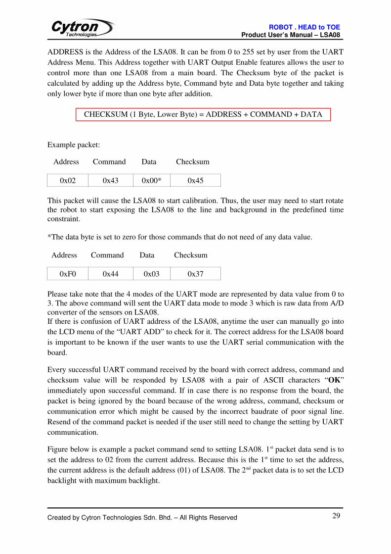
For LSA08 Serial Communication (UART), a command needs to send to enter menu mode
Table below shown command reference table for UART and UART Command Packet
Format. Table shows the selectable baudrate for LSA08.
Setting Baudrate(bps)
0 9600
1 19200
2 38400
3 57600
4 115200
5 230400
Command and data reference table for the UART:
Command
(ASCII)
Hexadecimal
ValueDescription Data (Hexadecimal value)
C 0x43 Calibration 0x00
L 0x4C Mode (Dark On/Light On) 0x01(Dark on), 0x00 (light on)
T 0x54 Line Threshold 0x00 - 0x07
O 0x4F Offset 0x00 - 0x32
J 0x4A Junction Width 0x01 - 0x08
A 0x41 UART Address 0x00 - 0xFF
B 0x42 LCD Backlight 0x00 - 0x0A
S 0x53 LCD Contrast 0x00 - 0xFF
R 0x52 UART Baudrate 0x00 - 0x05
D 0x44 UART Data Output Mode 0x00 - 0x03
UART Command Packet Format (4 bytes):
ADDRESS COMMAND DATA CHECKSUM
Created by Cytron Technologies Sdn. Bhd. – All Rights Reserved 28
ROBOT . HEAD to TOE Product User’s Manual – LSA08
ADDRESS is the Address of the LSA08. It can be from 0 to 255 set by user from the UART
Address Menu. This Address together with UART Output Enable features allows the user to
control more than one LSA08 from a main board. The Checksum byte of the packet is
calculated by adding up the Address byte, Command byte and Data byte together and taking
only lower byte if more than one byte after addition.
Example packet:
Address Command Data Checksum
0x02 0x43 0x00* 0x45
This packet will cause the LSA08 to start calibration. Thus, the user may need to start rotate
the robot to start exposing the LSA08 to the line and background in the predefined time
constraint.
*The data byte is set to zero for those commands that do not need of any data value.
Address Command Data Checksum
0xF0 0x44 0x03 0x37
Please take note that the 4 modes of the UART mode are represented by data value from 0 to
3. The above command will sent the UART data mode to mode 3 which is raw data from A/D
converter of the sensors on LSA08.
If there is confusion of UART address of the LSA08, anytime the user can manually go into
the LCD menu of the “UART ADD” to check for it. The correct address for the LSA08 board
is important to be known if the user wants to use the UART serial communication with the
board.
Every successful UART command received by the board with correct address, command and
checksum value will be responded by LSA08 with a pair of ASCII characters “OK”
immediately upon successful command. If in case there is no response from the board, the
packet is being ignored by the board because of the wrong address, command, checksum or
communication error which might be caused by the incorrect baudrate of poor signal line.
Resend of the command packet is needed if the user still need to change the setting by UART
communication.
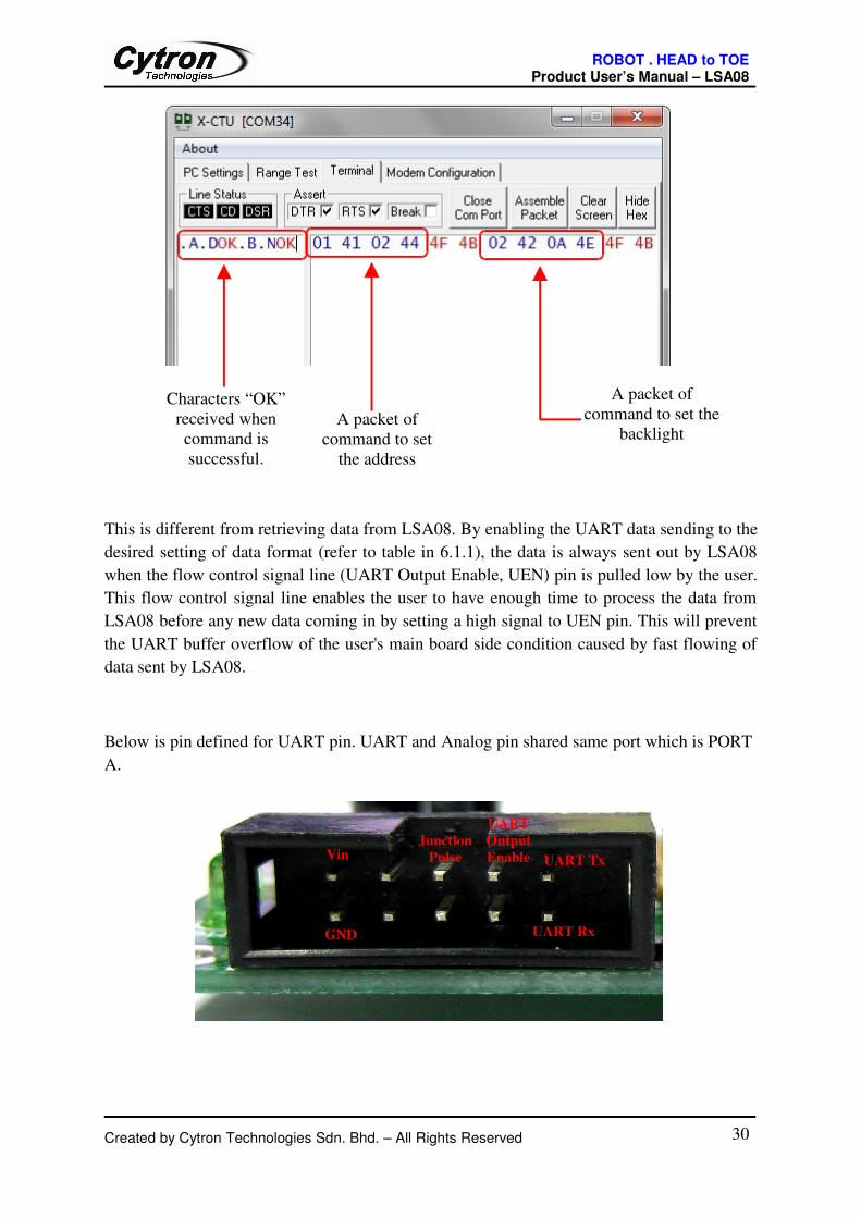
Figure below is example a packet command send to setting LSA08. 1st packet data send is to
set the address to 02 from the current address. Because this is the 1st time to set the address,
the current address is the default address (01) of LSA08. The 2nd packet data is to set the LCD
backlight with maximum backlight.
Created by Cytron Technologies Sdn. Bhd. – All Rights Reserved 29
CHECKSUM (1 Byte, Lower Byte) = ADDRESS + COMMAND + DATA
ROBOT . HEAD to TOE Product User’s Manual – LSA08
This is different from retrieving data from LSA08. By enabling the UART data sending to the
desired setting of data format (refer to table in 6.1.1), the data is always sent out by LSA08
when the flow control signal line (UART Output Enable, UEN) pin is pulled low by the user.
This flow control signal line enables the user to have enough time to process the data from
LSA08 before any new data coming in by setting a high signal to UEN pin. This will prevent
the UART buffer overflow of the user's main board side condition caused by fast flowing of
data sent by LSA08.
Below is pin defined for UART pin. UART and Analog pin shared same port which is PORT
A.
Created by Cytron Technologies Sdn. Bhd. – All Rights Reserved 30
UART Tx
Junction
Pulse
UART Rx
UART
Output
EnableVin
GND
A packet of
command to set
the address
A packet of
command to set the
backlight
Characters “OK”
received when
command is
successful.
ROBOT . HEAD to TOE Product User’s Manual – LSA08
UART output enable signal pin (UEN) is for controlling the flow of data from the LSA08
board. This line will not affect the commands sent into the LSA08 board and responses of
LSA08 to the commands on UART serial communication line. Commands can be sent to the
LSA07 regardless the UEN line signal state either low or high and LSA08 will still response
accordingly. Commands and responses of command have higher priority than the data output
streams. Thus, LSA08 will process the command and response accordingly as soon as it
receives the full correct packet command.
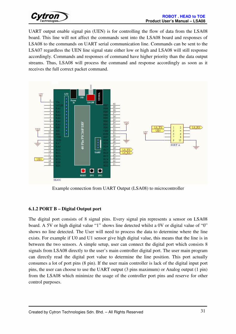
Example connection from UART Output (LSA08) to microcontroller
6.1.2 PORT B – Digital Output port
The digital port consists of 8 signal pins. Every signal pin represents a sensor on LSA08
board. A 5V or high digital value “1” shows line detected whilst a 0V or digital value of “0”
shows no line detected. The User will need to process the data to determine where the line
exists. For example if U0 and U1 sensor give high digital value, this means that the line is in
between the two sensors. A simple setup, user can connect the digital port which consists 8
signals from LSA08 directly to the user’s main controller digital port. The user main program
can directly read the digital port value to determine the line position. This port actually
consumes a lot of port pins (8 pin). If the user main controller is lack of the digital input port
pins, the user can choose to use the UART output (3 pins maximum) or Analog output (1 pin)
from the LSA08 which minimize the usage of the controller port pins and reserve for other
control purposes.
Created by Cytron Technologies Sdn. Bhd. – All Rights Reserved 31

ROBOT . HEAD to TOE Product User’s Manual – LSA08
Table below shows the pins defined for digital output port.
Pin Description Symbol
1 Digital Output 1 (Sensor 1) O0
2 Digital Output 2 (Sensor 2) O1
3 Digital Output 3 (Sensor 3) O2
4 Digital Output 4 (Sensor 4) O3
5 Digital Output 5 (Sensor 5) O4
6 Digital Output 6 (Sensor 6) O5
7 Digital Output 7 (Sensor 7) O6
8 Digital Output 8 (Sensor 8) O7
9 Vin (12V) VIN
10 GND GND
Created by Cytron Technologies Sdn. Bhd. – All Rights Reserved 32
Vin
GND
Digital
Output 1
Digital
Output 2
Digital
Output 3
Digital
Output 4
Digital
Output 6
Digital
Output 8
Digital
Output 5Digital
Output 7
ROBOT . HEAD to TOE Product User’s Manual – LSA08
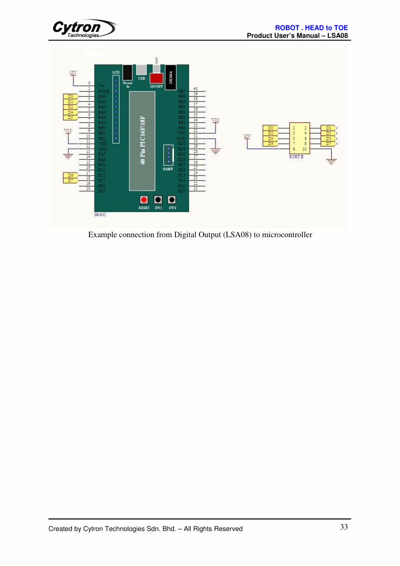
Example connection from Digital Output (LSA08) to microcontroller
Created by Cytron Technologies Sdn. Bhd. – All Rights Reserved 33
ROBOT . HEAD to TOE Product User’s Manual – LSA08
6.1.3 PORT C – External LCD
Another port provided is PORT C which is for the use of external LCD. Jumper on LSA08
needs to be set to Ext for the External LCD to operate. The contrast value for the LCD need
to be readjusted because every LCD has different voltage range for the liquid crystal in order
to display properly. The contrast is the second menu of the LSA08.
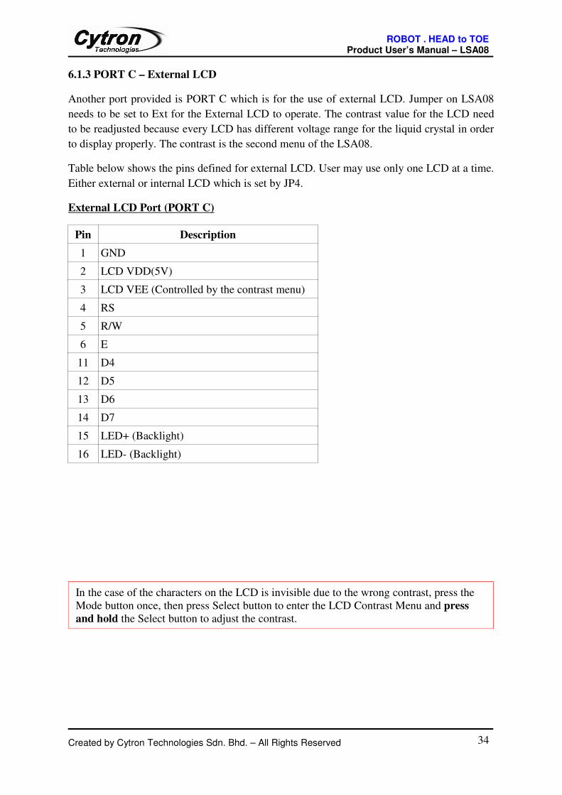
Table below shows the pins defined for external LCD. User may use only one LCD at a time.
Either external or internal LCD which is set by JP4.
External LCD Port (PORT C)
Pin Description
1 GND
2 LCD VDD(5V)
3 LCD VEE (Controlled by the contrast menu)
4 RS
5 R/W
6 E
11 D4
12 D5
13 D6
14 D7
15 LED+ (Backlight)
16 LED- (Backlight)
Created by Cytron Technologies Sdn. Bhd. – All Rights Reserved 34
In the case of the characters on the LCD is invisible due to the wrong contrast, press the
Mode button once, then press Select button to enter the LCD Contrast Menu and press
and hold the Select button to adjust the contrast.
ROBOT . HEAD to TOE Product User’s Manual – LSA08
7. WARRANTY
� Product warranty is valid for 6 months.
� Warranty only applies to manufacturing defect.
� Damage caused by misuse is not covered under warranty.
� Warranty does not cover freight cost for both ways.
Created by Cytron Technologies Sdn. Bhd. – All Rights Reserved 35
Prepared by
Cytron Technologies Sdn. Bhd.
19, Jalan Kebudayaan 1A,
Taman Universiti,
81300 Skudai,
Johor, Malaysia.
Tel: +607-521 3178
Fax: +607-521 1861
URL: www.cytron.com.my
Email: [email protected]