Adv. Funct. Mater., 20
17
www.afm-journal.de FEATURE ARTICLE © 2010 WILEY-VCH Verlag GmbH & Co. KGaA, Weinheim Adv. Funct. Mater. 2010, 20, 3818–3834 3818 www.MaterialsViews.com wileyonlinelibrary.com By Hyun-Kon Song, Kyu Tae Lee, Min Gyu Kim, Linda F. Nazar,* and Jaephil Cho* 1. Introduction Applications of Li-ion cells have been diversified from mobile devices such as cell phones and laptop computers to electric vehicles, power tools, and stationary energy storage. To satisfy the needs of new applications, cells are required to be enhanced in terms of performance quadrilogy (energy density, power den- sity, cyclability, and safety). Depending on applications, some performance properties are relatively more emphasized than others, for example, high power densities for power tools, power densities as well as safety for hybrid electric vehicles, and energy density as well as cost for stationary energy storage. The best and most direct strategy to achieve the desired performances is to use materials that possess the desired properties, while cell perform- ances can be improved only in a limited way by optimizing cell structures. Mixed metal oxides with layered structure, manga- nese oxides with spinel structure, and polyanion-based materials with olivine structure have been highlighted as cathode materials for new applications, even if LiCoO 2 still prevails over alternatives in mobile elec- tronics (e.g., smart phones). Each material has its own merits and demerits compared with other candidates. Therefore, research and development focuses on improving upon material demerits From this point of view, nanostructuring electrode mate- rials has been proved to be one of the most helpful strategies. Layered mixed metal oxides are pre- pared from a series of solid solutions from Li 2 MnO 3 (Li[Li 1/3 Mn 2/3 ]O 2 ) to LiMO 2 (M = Cr, Ni, and Co) at high firing temperature ( >700 °C). For example, Li[Li 0.2 Cr 0.4 Mn 0.4 ] O 2 is equivalent to the solid solution of Li 2 MnO 3 and LiCrO 2 . Li 2 MnO 3 , one end of the spectrum of solid solutions, is electro- chemically inactive since Mn 4 + in Li 2 MnO 3 cannot be oxidized beyond the 4 + oxidation state in order to extract Li from its lat- tice. [1–7] Hence, substitution of redoxable transition metals into the Mn 4 + sites is essential to make Li 2 MnO 3 electrochemically active. Cells based on the cathode materials exhibited an irre- versible capacity at around 4.5 to 4.7 V when charged to ∼4.8 V. After the first charge process, the materials were reversibly cycled with a high capacity over 200 mAh g −1 . [8] The spinel Li x Mn 2 O 4 with a strong edge-shared [Mn 2 ]O 4 octa- hedral framework exhibits good structural stability during the charge/discharge process. [9–12] However, 80% of Li + is revers- ibly inserted and extracted at ∼4 V versus Li/Li + , which limits its capacity to <120 mAh g −1 . [13,14] The additional insertion of Li + into the empty octahedral sites of the [Mn 2 ]O 4 framework at ∼3 V versus Li/Li + accompanies a macroscopic structural transition from cubic to tetragonal symmetry due to the Jahn–Teller distor- tion associated with the high spin Mn 3 + :t 2 g 3 e g 1 ions, resulting in a huge volume change and severe capacity fade. [15] Therefore, the capacity in the 3 V region could not be used in practical cells. Following the introduction of LiFePO 4 by Goodenough et al., [16] polyanion (XO 4 y − : X = P, S, Si, As, Mo, W)-based materials have been extensively studied as cathode materials in lithium- ion batteries. In particular, PO 4 2 − and SO 4 2 − polyanions have been a focus of studies because of the favorable increase of redox potential—and hence energy density—these anions display owing to their strong inductive effect. Iron- and manganese- based polyanion compounds are particularly promising candi- dates due to their advantages of being abundant, environmen- tally benign, and inexpensive. However, polyanion materials have critical disadvantages of poor electronic and ionic conductivities. Power density (rate capability) of these cathode materials with bulk sizes is generally low due to the high level of polarization Recent Progress in Nanostructured Cathode Materials for Lithium Secondary Batteries Diversified and extended applications of lithium-ion batteries demand the development of more enhanced materials that can be achieved by sophis- ticated synthetic methods. Combination of novel materials with strategic design of their shape on the nanometer scale enables a breakthrough to overcome problems experienced by present technologies. In this feature article, an overview is given of Mn-based and polyanion-based cathode materials with nanoscale features for lithium-ion batteries as materials to replace conventional bulk cathode materials. Various synthetic methods coupled with nanostructuring as well as the benefits obtained from the nanostructure are described. DOI: 10.1002/adfm.201000231 [∗] Prof. H.-K. Song, Prof. K. T. Lee, Prof. J. Cho Interdisciplinary School of Green Energy Ulsan National Institute of Science & Technology (UNIST) Ulsan 689–798, Korea E-mail: [email protected] Prof. L. F. Nazar University of Waterloo Department of Chemistry 200 University Avenue west Waterloo, Ontario, Canada N2L 3G1 E-mail: [email protected] Dr. M. G. Kim Beamline Research Division Pohang Accelerator Laboratory Pohang 790–784, Korea
-
Upload
nguyenthuan -
Category
Documents
-
view
242 -
download
0
Transcript of Adv. Funct. Mater., 20

www.afm-journal.de
FEATU
RE
ARTI
CLE
3818
www.MaterialsViews.com
Recent Progress in Nanostructured Cathode Materials for Lithium Secondary Batteries
By Hyun-Kon Song , Kyu Tae Lee , Min Gyu Kim , Linda F. Nazar , * and Jaephil Cho *
Diversifi ed and extended applications of lithium-ion batteries demand the development of more enhanced materials that can be achieved by sophis-ticated synthetic methods. Combination of novel materials with strategic design of their shape on the nanometer scale enables a breakthrough to overcome problems experienced by present technologies. In this feature article, an overview is given of Mn-based and polyanion-based cathode materials with nanoscale features for lithium-ion batteries as materials to replace conventional bulk cathode materials. Various synthetic methods coupled with nanostructuring as well as the benefi ts obtained from the nanostructure are described.
1. Introduction
Applications of Li-ion cells have been diversifi ed from mobile devices such as cell phones and laptop computers to electric vehicles, power tools, and stationary energy storage. To satisfy the needs of new applications, cells are required to be enhanced in terms of performance quadrilogy (energy density, power den-sity, cyclability, and safety). Depending on applications, some performance properties are relatively more emphasized than others, for example, high power densities for power tools, power densities as well as safety for hybrid electric vehicles, and energy density as well as cost for stationary energy storage. The best and most direct strategy to achieve the desired performances is to use materials that possess the desired properties, while cell perform-ances can be improved only in a limited way by optimizing cell structures. Mixed metal oxides with layered structure, manga-nese oxides with spinel structure, and polyanion-based materials with olivine structure have been highlighted as cathode materials
© 2010 WILEY-VCH Verlag GmbH & Co. KGaA, Weinhewileyonlinelibrary.com
DOI: 10.1002/adfm.201000231
[∗] Prof. H.-K. Song , Prof. K. T. Lee , Prof. J. Cho Interdisciplinary School of Green Energy Ulsan National Institute of Science & Technology (UNIST) Ulsan 689–798, Korea E-mail: [email protected] Prof. L. F. Nazar University of Waterloo Department of Chemistry 200 University Avenue west Waterloo, Ontario, Canada N2L 3G1 E-mail: [email protected] Dr. M. G. Kim Beamline Research Division Pohang Accelerator Laboratory Pohang 790–784, Korea
for new applications, even if LiCoO 2 still prevails over alternatives in mobile elec-tronics (e.g., smart phones). Each material has its own merits and demerits compared with other candidates. Therefore, research and development focuses on improving upon material demerits From this point of view, nanostructuring electrode mate-rials has been proved to be one of the most helpful strategies.
Layered mixed metal oxides are pre-pared from a series of solid solutions from Li 2 MnO 3 (Li[Li 1/3 Mn 2/3 ]O 2 ) to LiMO 2 (M = Cr, Ni, and Co) at high fi ring temperature ( > 700 ° C). For example, Li[Li 0.2 Cr 0.4 Mn 0.4 ]
O 2 is equivalent to the solid solution of Li 2 MnO 3 and LiCrO 2 . Li 2 MnO 3 , one end of the spectrum of solid solutions, is electro-chemically inactive since Mn 4 + in Li 2 MnO 3 cannot be oxidized beyond the 4 + oxidation state in order to extract Li from its lat-tice. [ 1–7 ] Hence, substitution of redoxable transition metals into the Mn 4 + sites is essential to make Li 2 MnO 3 electrochemically active. Cells based on the cathode materials exhibited an irre-versible capacity at around 4.5 to 4.7 V when charged to ∼ 4.8 V. After the fi rst charge process, the materials were reversibly cycled with a high capacity over 200 mAh g − 1. [ 8 ]
The spinel Li x Mn 2 O 4 with a strong edge-shared [Mn 2 ]O 4 octa-hedral framework exhibits good structural stability during the charge/discharge process. [ 9–12 ] However, 80% of Li + is revers-ibly inserted and extracted at ∼ 4 V versus Li/Li + , which limits its capacity to < 120 mAh g − 1 . [ 13,14 ] The additional insertion of Li + into the empty octahedral sites of the [Mn 2 ]O 4 framework at ∼ 3 V versus Li/Li + accompanies a macroscopic structural transition from cubic to tetragonal symmetry due to the Jahn–Teller distor-tion associated with the high spin Mn 3 + :t 2 g 3 e g 1 ions, resulting in a huge volume change and severe capacity fade. [ 15 ] Therefore, the capacity in the 3 V region could not be used in practical cells.
Following the introduction of LiFePO 4 by Goodenough et al., [ 16 ] polyanion (XO 4 y − : X = P, S, Si, As, Mo, W)-based materials have been extensively studied as cathode materials in lithium-ion batteries. In particular, PO 4 2 − and SO 4 2 − polyanions have been a focus of studies because of the favorable increase of redox potential—and hence energy density—these anions display owing to their strong inductive effect. Iron- and manganese-based polyanion compounds are particularly promising candi-dates due to their advantages of being abundant, environmen-tally benign, and inexpensive. However, polyanion materials have critical disadvantages of poor electronic and ionic conductivities.
Power density (rate capability) of these cathode materials with bulk sizes is generally low due to the high level of polarization
im Adv. Funct. Mater. 2010, 20, 3818–3834

FEATU
RE A
RTIC
LE
www.afm-journal.dewww.MaterialsViews.com
Linda Nazar is Professor of Chemistry at the University of Waterloo, Canada. She received her Ph.D. in Chemistry from the University of Toronto (Canada) in 1984. She was a recent member of a Department of Energy (US) panel to chart new direc-tions for Electrochemical Energy Storage. She is the 2009–10 Moore Distinguished
Scholar at the California Institute of Technology. Her current research is focused on nanomaterials for Li-ion and Na-ion batteries, Li-sulfur and Li-air batteries, and fuel cell catalysts.
Jaephil Cho is a pro-fessor and a dean in Interdisciplinary School of Green Energy at Ulsan National Institute of Science and Technology (Korea). He received his Ph. D. (1995) in Ceramic Engineering from Iowa State University (USA). He is a director of Converging Research Center for Innovative Battery
Technologies supported by Ministry of Eduation, Scienec & Technology in Korea. His current research is focused mainly on nanomaterials for energy conversion and storage, nanos-cale coating, and safety enhancement of the Li-ion batteries.
at high charge/discharge rates (above 2 C). This high polari-zation is believed to result from slow lithium diffusion or low electric conductivity in the active material. Therefore, the nanostructured approach was introduced to overcome these shortcomings by decreasing diffusion paths for mass trans-port and increasing the surface area for charge transfer. This strategy was highly effective in greatly enhancing their electro-chemical performance.
This review provides an overview of the synthesis, the nanoscale-size effect, and a survey of promising candidates based on nanostructured materials for lithium-ion batteries in recent years. Mixed metal oxides with layered structure, man-ganese oxides with spinel structure, and polyanion-based mate-rials with olivine structure are focused upon. Various synthetic methods coupled with nanostructuring are described, empha-sizing the benefi ts obtained from the nanostructure.
2. Nanostructured Layered Mixed Metal Oxides
Layered mixed metal oxides as cathode materials (e.g., LiNi 0.8 Co 0.15 Al 0.05 O 2 or LiNi 1/3 Co 1/3 Al 1/3 O 2 ) have been prepared conventionally by solid state reactions at relatively high tem-perature (above 700 ° C), resulting in micrometer-sized particles ( > 5 μ m). [ 17–20 ] However, the macroscopic dimensions of conven-tionally synthesized particles lead to the demerits of limited kinetics of lithium insertion/extraction. Nanoparticles with various mor-phologies ( < 100 nm) are kinetically more favorable so that good performances are achieved at high rates with the cathode mate-rials. To synthesize the nanometer-sized particles, a low temper-ature synthetic method via soft chemistry has been extensively studied. [ 21–25 ] The ion exchange method is an example of soft chemistry that can provide well-controlled nanoparticles with a narrow particle size distribution even below 150 ° C.
Layered transition metal oxide bronzes synthesized via the ion exchange method below 300 ° C showed poor crystallinity due to the imperfect stoichiometries caused by water molecules and protons as impurities, leading to unstable structures during charge/discharge cycles. [ 26,27 ] Anhydrous and stoichiometric LiMnO 2 , analogous to LiCoO 2 , was obtained by exchanging Na + in NaMnO 2 with Li + through refl uxing an excess of LiCl or LiBr in n-hexanol at 145 to 150 ° C for 6 to 8 h. [ 28,29 ] The Mn 3 + disorder was estimated at 10% Mn 3 + in Li + sites in the layered LiMnO 2 . A phase transition from the layered structure to a spinel-like one during Li intercalation/deintercalation was caused by the movement of disordered Mn 3 + to adjacent layers, resulting in capacity fading.
Birnessites (A x MnO 2 ± x (H 2 O) y ) have reportedly been used as precursors for the synthesis of layered materials because of rel-ativley easy ion-exchanges of A and Mn ions with Li and other transition metals at < 200 ° C without disturbing its pristine structure. Their two-dimensional layered structure consists of edge-shared MnO 6 octahedra with cations and water molecules that occupy the interlayer region. [ 30–34 ] The temperature deter-mines the structure of the fi nal products from birnnesite in hydrothermal processes: spinel at 150 ° C and layered α -NaFeO 2 at 200 ° C. Also, the morphology of particles can be controlled by lithium salt reacted with the layered α -NaFeO 2 : nanowires from LiNO 3 and nanoplates from LiOH.
© 2010 WILEY-VCH Verlag GAdv. Funct. Mater. 2010, 20, 3818–3834
2.1. Ni–Mn-Based System
In the solid solution series (Li[Mn (2−x)/3 M x Li (1−x)/3 ]O 2 or Li[Mn (2/3−x) M x Li (1/3–2x/3) ]O 2 ) between Li 2 MnO 3 and LiMO 2 (M = Ni, Co, and Cr), lithium is extracted from the solid solution in two steps during the initial charge: i) from the LiMO 2 component below 4.5 V with oxidation of M-ion and then ii) from the Li 2 MnO 3 component above 4.5 V with a simultaneous release of oxygen. The latter step leads to a loss of Li 2 O from the Li 2 MnO 3 compo-nent to yield an electrochemically active MnO 2 component. [ 35 ] For instance, Li[Ni 0.2 Li 0.2 Mn 0.6 ]O 2 , which was an isostructure to O3-LiCoO 2 , showed a charge capacity as high as 320 mAh g − 1 upon charging to 4.8 V. [ 36 ] Since the theoretical capacity of this cathode, based solely upon oxidation of the Ni, is 126 mAh g − 1 , the additional capacity contribution was reported to be from a net loss of lithium and oxygen from the cathode at voltages above 4.5 V. Accordingly, a large irreversible capacity loss occured due to the partial loss of the lithium ions extracted during the fi rst cycle. In spite of their high capacity, these bulk materials showed rapid capacity fade and poor rate capability. To enhance such capacity retention and rate performances, dimensional control is essential.
mbH & Co. KGaA, Weinheim 3819wileyonlinelibrary.com

FEATU
RE
ARTI
CLE
3820
www.afm-journal.dewww.MaterialsViews.com
Figure 1 . a,b) SEM images of [Ni 0.25 Li 0.15 Mn 0.6 ]O 2 nanoplates (a) and nanowires (b) obtained from hydrothermal heating at 200 ° C at different pH (2 and 10, respectively) for 5 h. c) Charge and discharge curves for the nanowires. d) Discharge capacity obatained at various rates. Reproduced with permission. [ 39 ] Copyright 2009, Royal Society of Chemistry.
A layered Ni 0.3 Mn 0.7 O 2 precursor has been obtained through the ion-exchange reaction of birnessite K 0.32 MnO 2 with NiCl 2 · 2H 2 O in aqueous solution at room temperature for 5 days. [ 37,38 ] Depending on pH controlled by altering the ratio of Li precursor (LiOH · H 2 O or LiNO 3 ) to water content, Li[Ni 0.25 Li 0.15 Mn 0.6 ]O 2 derivatives of different phases and morphologies were synthe-sized after fi ring. At pH 10, as shown in Figure 1a , the layered Li[Ni 0.25 Li 0.15 Mn 0.6 ]O 2 phase at 200 ° C shows a nanoplate-shape with ∼ 10 nm thick basal planes of ∼ 100 nm dimension. [ 39 ] At pH 2, pure nanowires of the same phase were obtained with diam-eters of ∼ 30 nm and lengths more than 1 μ m (Figure 1b ). High-resolution transmission electron microscopy (TEM) images showed that the distance between neighboring lattice fringes has an approximate d -spacing value of 4.7 Å, which corresponds to the (003) plane of the hexagonal layered phase. [ 37,38 ] The Brun-auer–Emmett–Teller (BET) surface area of the nanowires was 65 m 2 g − 1 . [ 37,38 ] Li[Ni 0.25 Li 0.15 Mn 0.6 ]O 2 can grow with an aniso-tropic crystal structure as one-dimensional nanowires in high chemical potential surroundings, which were created by the release of the stored energy in the pre-nucleated metastable phase during heating at the appropriate temperature. [ 40 ]
Figure 1c shows the voltage profi les of Li[Ni 0.25 Li 0.15 Mn 0.6 ]O 2 nanowires after 1, 30, 50, and 80 cycles between 2 and 4.8 V at a rate of 0.3 C ( = 120 mA g − 1 ) in coin-type half cells. The fi rst charge and discharge capacities are 367 mAh g − 1 and 311 mAh g − 1 , respectively, showing a coulombic effi ciency of 85%. The extraction of the Li + ions remaining in the Li layer and the concomitant oxygen leads to an irreversible capacity loss in the initial cycle, as clearly demonstrated in the cycling plot. Such extensive removal of Li 2 O from the cathode can lead to physical damage on the electrode surface during cycling and then an increase of cell impedance. Figure 1d shows cycle life performance and rate capabilities of the nanoplates and
© 2010 WILEY-VCH Verlag GmbH & Co. KGaA, Weiwileyonlinelibrary.com
nanowires at different C rates between 4.8 and 2.0 V in coin-type half cells. The rate capabilities of the nanowires are also far superior to those of their nanoplate counter-parts, which exhibit over 50% capacity loss at a 7 C rate cycling. When using bulk par-ticles, the phenomenon resulted in severe capacity fading at higher current rates. In the nanostructured electrode, however, better rate capabilities were due to the decreased distance over which Li + must diffuse in the solid state.
2.2. Co–Mn-Based System
Depending on the composition of the pre-cursors (Co 0.35 Mn 0.65 O 2 and LiOH · H 2 O), a spinel or a layered phase of Co–Mn-based sys-tems was obtained. [ 37,38 ] A spinel phase was developed at 150 ° C with the weight ratio of Co 0.35 Mn 0.65 O 2 to LiOH · H 2 O = 1:1. On the other hand, a major layered hexagonal phase of Li 0.93 [Li 0.21 Co 0.27 Mn 0.51 ]O 2 nanoplates was obtained at 200 ° C by increasing the concentra-tion of LiOH · H 2 O fourfold. Rate performance
of the Li 0.93 [L 0.21 Co 0.27 Mn 0.51 ]O 2 cathodes between 0.1 C and 4 C rate was superior to that of a nanocrystalline Li[Li 0.2 Ni 0.2 Mn 0.6 ]O 2 cathode (particle size = 80 to 200 nm mixed with 1 to 20 μ m) prepared by a combustion method. [ 36 , 41 ] The improved rate capa-bility of the Li 0.93 [Li 0.21 Co 0.27 Mn 0.51 ]O 2 cathode is believed to be due to its nanoplate-like morphology with a thickness of 20 nm that enables the shorter Li diffusion length.
To investigate structural changes of the layered Li 0.93 [Li 0.21 Co 0.27 Mn 0.51 ]O 2 phase during charging, Co and Mn K-edge XANES (X-ray absorption near edge spectra) features were traced by potential energy and intensity at edge, pre-edge, and shoulder as shown in Figure 2 . In terms of potential energy, the peaks A and C (corresponding to pre-edge and edge) for Co were predominantly shifted toward the higher energy region while the Mn K-edge peaks did not change. The trivalent Co 3 + low-spin state was gradually oxidized to Co 4 + during delithia-tion (charge) due primarily to the higher energy shift of pre-edge peak A while that of the Mn K-edge were relatively con-stant. In terms of intensity, delithiation increases the intensity of peak A and decreases that of peak C in all Co and Mn K-edge XANES. This phenomenon is indicative of a gradual evolution of more distorted octahedral sites. [ 42 ] The systematic tendencies of the peak features are closely associated with the change of the ground state for the oxygen ion because the peak indicated the existence of a | 3d n + 1 L ⟩ state ( L indicates a hole state in the oxygen 2p band) in the ground state. A more oxidative and cov-alent O − 2 + δ d state in the uncycled sample is changed to a more reduced O 2 − state. Because delithiation gives rise to a decrease of the hole state ( L ) in the oxygen ion, the hole site is transferred to the TM site for charge compensation. [ 19 ] In delithiation, the | 3d 5 ⟩ states of Co 4 + -O 2 − , as other hole states, are newly evolved and then become more dominant than the corresponding | 3d 6 L ⟩ state of the ligand-to-metal charge transfer (LMCT) process.
nheim Adv. Funct. Mater. 2010, 20, 3818–3834

FEATU
RE A
RTIC
LE
www.afm-journal.dewww.MaterialsViews.com
Figure 2 . a,b) Co and Mn K-edge XANES spectra of the layered Li 0.93 [L 0.21 Co 0.27 Mn 0.51 ]O 2 phase during charge. c,d) Change of peak potential at pre-edge, shoulder and edge with potential during charge and discharge.
This means that the hole states are relatively localized at the Co 4 + atomic site under the local structural distorted environ-ment by the delithiation. [ 35 ] It should be noted that the constant peak variations above 4.5 V of the Co K-edge XANES indicate that the extraction of the oxygen from the materials played a major role in contributing to the capacity increase.
In the discharge process (lithiation), the XANES features for a fully relithiated state return to that of the electrochemical untreated sample. This means that the fi rst charge-discharge process is electrochemically reversible from the point of view of
© 2010 WILEY-VCH Verlag GmbH & Co. KGaA, WeinhAdv. Funct. Mater. 2010, 20, 3818–3834
the electronic structure of the Co ion and the local structures of the octahedra. The oxida-tion state of Mn ion did not change during the charge/discharge. The evidence for this is supported by the lack of spectral change of the pre-edge peak position for the 1 s → 3 d transition. Although some changes in the shape of the Mn K-edge were observed, these are ascribed to the rearrangement of the Mn local structure with no signifi cant zchange in oxidation state of the Mn ions. [ 19 ]
3. Nanostructured LiMn 2 O 4 Spinels
3.1. One- and Three-Dimensional Spinel Cathodes
A wide variety of synthetic approaches for the synthesis of LiMn 2 O 4 nanoparti-cles (nanotubes, nanorods, nanowires, and hollow morphologies) have been developed to improve the rate capabilities of spinel LiMn 2 O 4 at room temperature. The rate-determining step in the electrodes of lithium ion batteries is supposed to be a solid state diffusion. The faster kinetics are expected with the smaller particle size because diffu-sion length is shorter. [ 43–45 ] It has been dem-onstrated that capacity of LiMn 2 O 4 can be enhanced by decreasing the average grain size of the oxide. [ 46,47 ] Therefore, nanotubular LiMn 2 O 4 would show possible advantages such as faster diffusion kinetics over nano-particle electrodes. Improvement of charge/discharge performance was achieved with the electrode of LiMn 2 O 4 /polypyrrole composite nanotubes. [ 48 ] After dissolving the Al 2 O 3 tem-plate membrane, the resulting nanotubule array of LiMn 2 O 4 was coated with polypyrrole to investigate the galvanostatic charge/dis-charge characteristics. The polypyrrole-coated LiMn 2 O 4 tubule electrodes exhibited higher capacities than the thin-fi lm counterpart pre-pared under the same conditions. Discharge capacity was signifi cantly improved by 12 times at the discharge rate of 1 mA cm − 2 , compared to its thin fi lm counterpart. The observed
he tubule electrode resulted from two effects:
high capacity of ta decrease in real current density of high specifi c surface area at the tubule electrode and a decrease in thickness of LiMn 2 O 4 solid phase for Li ions to diffuse through during the charging and discharging reactions. A similar method using Al 2 O 3 template membrane was reported by Li et al. and they have demonstrated that open-ended nanotubes of spinel LiMn 2 O 4 were prepared on the basis of the obtained bulk by combined template syn-thesis and thermal decomposition of the sol–gel precur-sors within the pores of AAO membrane (with 200 nm pore,eim 3821wileyonlinelibrary.com

FEATU
RE
ARTI
CLE
3822
www.afm-journal.dewww.MaterialsViews.com
Figure 3 . Change in capacity with charge/discharge cycles at 30 mAg − 1 (0.3 C) between 3 V and 4.3 V at 50 ° C: for mesoporous and bulk Li 1.12 Mn 1.88 O 4 ; bulk and nanoparticulate Li 1.05 Mn 1.95 O 4 ; nanoparticu-late Li 1.12 Mn 1.88 O 4 . A TEM image of mesoporous Li 1.12 Mn 1.88 O 4 after 30 cycles was included. Reproduced with permission. [ 52 ] Copyright 2008, Wiley-VCH.
from Whatman). [ 49 ] The templates were dipped into the sol for 10 min and taken out for heating at 500 ° C for 8 h in air atmosphere. The entire “dip-anneal-dip” process was repeated three times for each sample, resulting in the formation of nanotubes within the template pores. The discharge capacities were 140 mAh g − 1 and 103 mAh g − 1 at a rate of 10 mA g − 1 and 40 mA g − 1 , respectively.
Zhang et al. only reported the synthesis of LiMn 2 O 4 spinel nanobelts from the spinel powder. [ 50 ] The synthetic procedure was as follows: LiMn 2 O 4 and sodium bis(2-ethylhexyl)sulfosucci-nate (NaAOT) were mixed with deionized water in a Tefl on-lined stainless autoclave. The autoclave was maintained at 160 ° C for 24 h and then air cooled to room temperature. The resulting product was collected and washed thoroughly with deionized water and ethanol, and fi nally dried at 80 ° C in an oven. The presence of NaAOT was reported to be crucial for the forma-tion of LiMn 2 O 4 nanobelts. Without NaAOT or in the presence of other surfactants, such as triblock copolymers poly(ethylene glycol)-block-poly(propylene glycol)-block-poly(ethylene glycol) and cetyltrimethylammonium bromide (CTAB), the nanobelt materials were not reported to be obtained.
Recently, LiMn 2 O 4 spinel nanowires were prepared by ion-exchanging Na 0.44 MnO 2 . As the fi rst step, Na 0.44 MnO 2 nanowires were obtained by dispersing commercial Mn 3 O 4 powders in aqueous NaOH solution in the Tefl on-lined autoclave at 180 ° C for 4 days. [ 51 ] Then, the resultant nanowires were ion-exchnaged with Li by using LiNO 3 and LiCl at 450 ° C for 1 h. Finally, LiMn 2 O 4 with cubic spinel nanowires were obtained after the sample was sintered at 800 ° C for 1 h. The capacity of the nanowires at 5 A g − 1 were superior to that of commercial counterparts (by Honjyo Chemical, Mitsui Metal, and Aldrich), even if all samples showed good capacity retention at least up to 100 cycles.
The mesoporous spinel cathode shown in Figure 3 was pre-pared by reducing mesoporous Mn 2 O 3 . [ 52 ] Mesoporous Mn 3 O 4 obtained from reduction of Mn 2 O 3 at 280 ° C for 3 h under a H 2 atmosphere (H 2 /Ar = 5:95) was mixed with LiOH · H 2 O in water, stirred until dry, and then was heated slowly at 350 ° C for 1 h. The resulting material was washed with water then dried at 120 ° C. An ordered mesoporous Li 1.12 Mn 1.88 O 4 spinel showed higher rate capability than the corresponding bulk material (50% higher specifi c capacity at a rate of 30 C, 3000 mAg − 1 ) at ambient temperature with good stability at 50 ° C, despite a high surface area of 90 m 2 g − 1 and no need for deliberate coating or doping with foreign ions. Similarly, well-ordered mesoporous spinel-structured LiMn 2 O 4 has been successfully prepared by annealing the lithiated mesoporous MnO 2 at a low tempera-ture of 350 ° C, in which the lithiated MnO 2 was obtained by the chemical lithiation of LiI with mesoporous MnO 2 . [ 53 ] Both low-temperature heat treatment [ 52 ] and chemical lithiation processes [ 53 ] could preserve the mesoporous structure of MnO 2 . In spite of high surface area of the mesoporous spinel, the capacity retention at 50 ° C is better than the others (Figure 3 ). Nanoparticles of Li 1.05 Mn 1.95 O 4 (BET surface area of 40 m 2 g − 1 compared with 1.5 m 2 g − 1 for the bulk material) result in even more severe capacity fading. Nanoparticles of Li 1.12 Mn 1.88 O 4 (40 m 2 g − 1 ) show lowering of the capacity to some extent presumably because of the higher average oxidation state leading to a higher Mn 4 + /Mn 3 + ratio at the surface. Thus, the Mn 3 + disproportiona-tion reaction is lowered leading to lesser Mn 2 + dissolution in
© 2010 WILEY-VCH Verlag Gwileyonlinelibrary.com
the electrolyte. [ 53,54 ] However, the mesoporous Li 1.12 Mn 1.88 O 4 material exhibited roughly comparable capacity retention to the corresponding bulk material (surface area 1.5 m 2 g − 1 ), despite the former having a surface area twice that of the Li 1.12 Mn 1.88 O 4 nanoparticles (90 m 2 g − 1 compared with 40 m 2 g − 1 ). These results demonstrated that the mesoporous Li 1.12 Mn 1.88 O 4 was more stable at elevated temperatures than the other materials. However, there were no cycling data at 60 ° C, at which Mn 3 + dissolution was reported to be more accelerated than at 50 ° C.
Three-dimensionally ordered macroporous (3DOM) LiMn 2 O 4 spinel was prepared by a colloidal templating process. [ 55 ] An opal structure consisting of monodispersed poly[styrene- co -methacrilic acid] beads (380 nm in diameter) was used as the template. After infi ltration of Li and Mn nitrates, the assembly was calcined in air at temperatures between 500 and 700 ° C. Void spaces between particles were fi lled with the fl uid precur-sors that were converted to a solid before removal of the tem-plate material. Intermediate reaction products formed when nitrates were used as precursors seem to play a key role in stabilizing the inorganic skeleton during the elimination of the template. Below 100 ° C, nitrates fi rst oxidize Mn(II) to form
mbH & Co. KGaA, Weinheim Adv. Funct. Mater. 2010, 20, 3818–3834

FEATU
RE A
RTIC
LE
www.afm-journal.dewww.MaterialsViews.com
Figure 4 . a) Schematic diagram of preparation of metal-oxide coated LiMn 2 O 4 nanoparticles using PVP. SEM images of the b) MnO 2 nanowires, c) LiMn 2 O 4 spinel nanorods, and d,e) ZrO 2 -coated spinel nanoparticles (1 wt% coating). Reproduced with permission. [ 64 ] Copyright 2008, Elsevier.
Mn 2 O 3 , which proved to be suffi ciently rigid to form 3DOM materials that retained the shape of the template when this became fl uid. Between 150 and 350 ° C, most Mn is converted to MnO 2 . Finally, Li nitrates react with MnO 2 to form spinel LiMn 2 O 4 around 400 ° C. At higher temperatures, direct conver-sion of Mn 2 O 3 to LiMn 2 O 4 and elimination of structural dis-order in LiMn 2 O 4 were observed.
Electrode density should be considered as one of the factors to affect energy density: higher electrode density leads to higher energy density. The higher electrode density can be easily achieved by using large particles of active materials: about 3.5 g cc − 1 from 10 μ m LiCoO 2 powders while 3.7 g cc − 1 from 20 μ m. Also, the large dimension of particles provides an additional advan-tage to minimize their surface area leading to reduce side reac-tions and irreversible capacity. In consequence, two-fold benefi ts can be obtained by increasing the size of LiMn 2 O 4 particles: high electrode density and low Mn dissolution. On the other hand, large size particles can conversely deteriorate the high rate capa-bility (power). Hence, the best way to improve both the charging time and the electrode density is to use bulk particles that con-sist of aggregated submicron-sized particles ( < 1 μ m).
3.2. Nanoclusted Spinel Cathodes
One of the important issues regarding the use of spinels (e.g., LiMn 2 O 4 ) as cathode materials is their large capacity loss observed during storage and cycling at elevated temperatures. [ 10 ] Self-dis-charge above 55 ° C and electrolyte decomposition at high voltages catalyzed by the electrode surface drastically affect cathode per-formance. [ 25 ] Also, capacity fade upon cycling depends largely on Mn dissolution through the following reaction due to the presence of trace acids, especially HF: 2Mn 3 + → Mn 4 + + Mn 2 + (with Mn 2 + going into the solution). [ 56,57 ] This reaction is accecerated with increasing BET surface area. A solution to this problem is to trap HF by means of HF scavengers as soon as it has been formed.
A solution alternative to scavenging HF is to creat a shell of inert and Li + -conductive materials around each LiMn 2 O 4 par-ticle for minimizing the interfacial area between cathodic mate-rials and electrolyte because the Mn dissolution occurs at the interface. In this regard, Al 2 O 3 , B 2 O 3 , ZnO, CoO, MgO, and LiCoO 2 -coated spinels have been reported. [ 58–63 ] The formation of such an inorganic passivation layer provides a two-fold ben-efi t in that it reduces disproportion/dissolution reactions and also minimizes electrolyte decomposition on the surface of the spinel. However, bulk spinels demontrated deteriorated rate capabilities, compared to nanostructuered counterparts.
Recently, more uniform coating method for the spinel nan-oparticles has been proposed to minimize the Mn dissolution ( Figure 4 a) Polyvinyl pyrrolidone (PVP) is fi rst capped onto the spinel nanorods prepared from the MnO 2 template, and metal cations from the coating precursor are then entangled in the backbone of the PVP-capped nanorods in the aqueous solution. Upon annealing at 600 ° C, the coated nanorods are divided into nanoparticles. Figure 4b to 4c show the scanning electron micro-scopy (SEM) images of b) the nanowire MnO 2 template with a diameter of ∼ 50 nm and a length of > 1 μ m and c) the LiMn 2 O 4 nanorod clusters prepared by the MnO 2 template. After reacting MnO 2 with Li acetate at 700 ° C for 10 h, the pristine primary
© 2010 WILEY-VCH Verlag GmAdv. Funct. Mater. 2010, 20, 3818–3834
particles consisting of nanowire clusters turned into nanorod clusters with individual nanorods ∼ 100 nm in diameter, and overall particle size was 5 to 10 μ m. Figure 4d and 4e show the SEM images of spinels after annealing 1wt.% ZrO 2 -coated spinel nanorods capped with PVP at 600 ° C (ZrC 2 O 4 precursor was used for ZrO 2 coating); the nanorods completely disappear and nanoparticles with ∼ 100 nm rock-shaped particles are observed.
When the spinel nanoclusters were coated with same con-centration of ZrC 2 O 4 precursor without using PVP to the coated samples, the coating thickness is not uniform, and coating thickness varies from 10 to 100 nm ( Figure 5 a). Depending on PVP amount used, the coating thickness can be controlled. When the amounts of metal oxide precursors were increased from 1 wt% to 2 wt%, the coating thickness increased from 6 nm (Figure 5c ) 12 nm (Figure 5d ). Because an increased
bH & Co. KGaA, Weinheim 3823wileyonlinelibrary.com

FEATU
RE
ARTI
CLE
3824
www.afm-journal.dewww.MaterialsViews.com
Figure 5 . TEM images of ZrO 2 -coated LiMn 2 O 4 spinel cathodes a) without using PVP, b) with using PVP and with coating concentrations of c) 1 wt%, where (c) is an expanded image from (b), and d) 2 wt%. e) Plot of discharge capacity vs. cycle number in the coin-type half cells containing uncoated, coated (1 and 2 wt%), and bulk LiMn 2 O 4 electrodes (particle size of bulk sample was ∼ 10 μ m).
surface area enhances the catalytic reactivity of the spinel sur-face with the electrolytes, the nanostructured materials show sig-nifi cantly decreased capacity retention above 50 ° C cycling com-pared to their bulk counterpart, which has a BET surface area of < 2 m 2 g − 1 . [ 64,65 ] Figure 5e provides discharge capacities of the uncoated and 1 and 2 wt% ZrO 2 -coated LiMn 2 O 4 and bulk counterpart as a function of cycle number at 60 ° C. However, when the coating concentration increases to 2 wt% (that is, the coating thickness is 12 nm), capacities decreases, but capacity retention is better than uncoated and bulk counterparts. How-ever, compared to the 1 wt% coated sample, capacities at each rates decreases, and this effect may be due to the thicker coating layer which impedes Li ion diffusivity (that is, a higher interfa-cial resistance). [ 53 , 64,65 ]
Sol–gel-driven Vox-coated LiMn 2 O 4 spinel nanorod clusters (clusterd partic size > 5 μ m) demonstrated rate capabilities
© 2010 WILEY-VCH Verlag Gwileyonlinelibrary.com
comparable to bare clusters at room temperature, but showed signifi cantly decreased Mn dissolution during storage at 80 ° C. [ 66 ] Using a MnO 2 template, uncoated and VOx-coated LiMn 2 O 4 spinel nanorod clusters were successfully prepared at 700 ° C. The coated spinels showed a fi rst discharge capacity of 130 and 127 mAh g − 1 , respectively, and showed 87% capacity retention at a high C rate of 7C. Furthermore, in spite of the high BET surface area of > 15 m 2 g − 1 , a higher V concentration at the particle surface signifi cantly decreased the dissolution of Mn under storage at 80 ° C.
As described in section 2.2, spinel nanowires were prepared from Co 0.35 Mn 0.65 O 2 nanowires. After stirring a solution con-taining 4 g of KMnO 4 and 100 mL of distilled water for 1 h at 40 ° C, we added the solution to 1 g of fumaric acid, resulting in the for-mation of a brown gel. This gel was annealed at 700 ° C for 8 h. The resultant dark black powders were washed with water three times and vacuum-dried at 200 ° C overnight. By using induc-tively coupled plasma (ICP)-mass spectrometry (MS) to analyze the sample, we confi rmed the presence of K 0.33 MnO 2 . The as-prepared K-birnessite was mixed with CoCl 2 · 6H 2 O: K 0.33 MnO 2 with a weight ratio of 17:1 in 100 mL distilled water at 21 ° C. The mixture was stirred for 8 days at room temperature and fi nally washed with water four times in order to remove any residues that did not participate in the reaction. Mixture of LiOH · H 2 O and Co 0.35 Mn 0.65 O 2 with a weight ratio of 1:1 at 150 ° C for 48 h led to formation of Li 1.01 Co 0.7 Mn 1.3 O 4 nanowires.
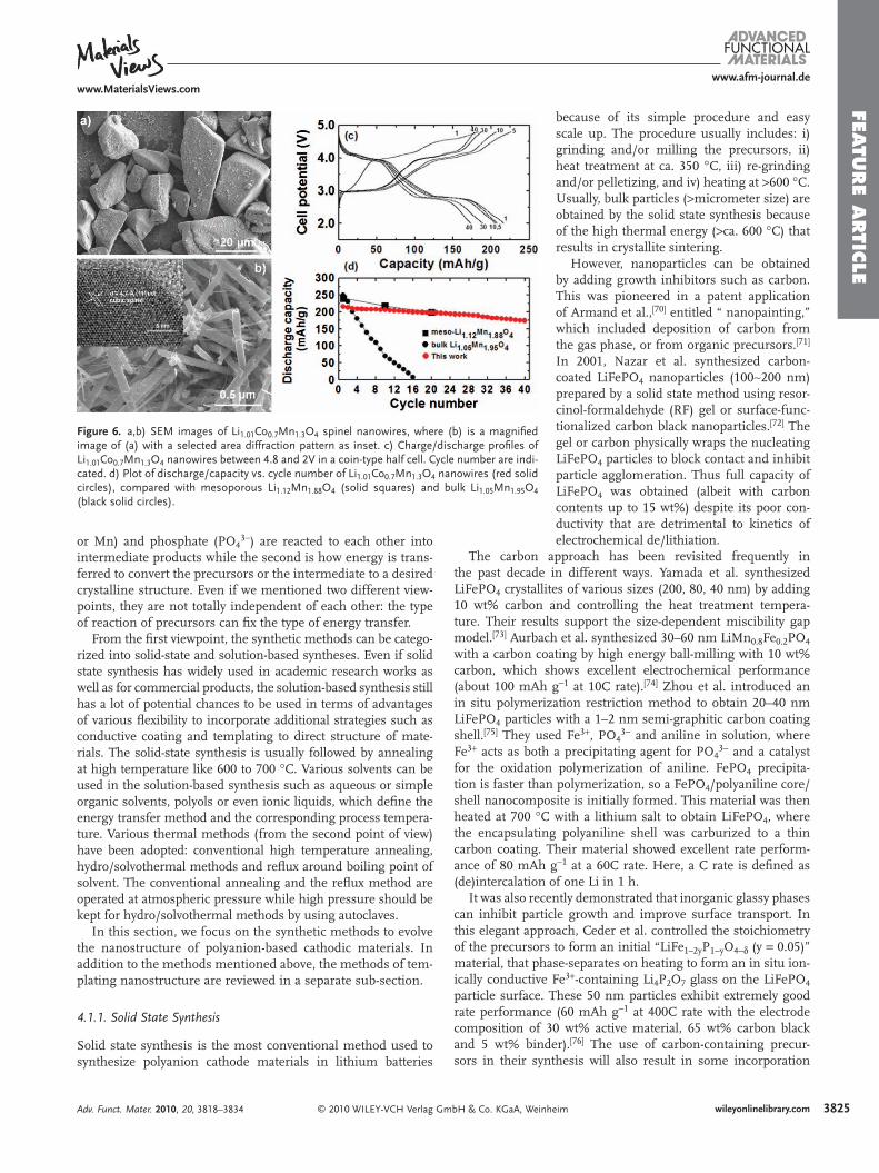
Although spinel materials are technologically relevant in 4 V region, it is interesting to explore the effect of the nanostruc-tured nanowires between 2 and 4.5 V region. The variation of the discharge capacity with the cycle number, where cycling is carried out between 2 and 4.5 V, is shown in Figure 6 for the bulk and nanowire Li 1.01 Co 0.7 Mn 1.3 O 4 and reference mesopo-rous Li 1.12 Mn 1.88 O 4 . [ 52 ] Even within 10 cycles the severe capacity fading of the bulk materials is evident, whereas the nanowire exhibits much better capacity retention. It is known that the capacity loss suffered on cycling bulk spinel with the composi-tion Li 1.05 Mn 1.95 O 4 between 3 and 4 V plateaus is related to the diffi culty of reversing the cubic (LiMn 2 O 4 )/tetragonal-(Li 2 Mn 2 O 4 ) phase transition associated with the 3 V plateau. [ 67 ] As a result, although capacity lowering occurs at both 3 and 4 V, the most severe loss of capacity is associated with the 3 V plateau, where the capacity retention is far better than for either of the bulk materials and mesoporous Li 1.12 Mn 1.88 O 4 spinel, implying that the cubic/tetragonal phase transformation is far more facile for the mesoporous material than the bulk. The capacity retention at 4 V is also somewhat better for the mesoporous material. As the nanometer-sized materials lead to the relief of strain during the structural phase transitions, these materials undergo the transi-tions in a more facile fashion than their bulk counterparts. [ 68,69 ]
4. Nanostructured Polyanion-Based Cathode Materials
4.1. Synthesis
Synthetic methods of polyanion-based cathodic materials can be classifi ed in terms of two different viewpoints. The fi rst point of view is related to how precursors of lithium, metal (M = Fe
mbH & Co. KGaA, Weinheim Adv. Funct. Mater. 2010, 20, 3818–3834
FEATU
RE A
RTIC
LE
www.afm-journal.dewww.MaterialsViews.com
Figure 6 . a,b) SEM images of Li 1.01 Co 0.7 Mn 1.3 O 4 spinel nanowires, where (b) is a magnifi ed image of (a) with a selected area diffraction pattern as inset. c) Charge/discharge profi les of Li 1.01 Co 0.7 Mn 1.3 O 4 nanowires between 4.8 and 2V in a coin-type half cell. Cycle number are indi-cated. d) Plot of discharge/capacity vs. cycle number of Li 1.01 Co 0.7 Mn 1.3 O 4 nanowires (red solid circles), compared with mesoporous Li 1.12 Mn 1.88 O 4 (solid squares) and bulk Li 1.05 Mn 1.95 O 4 (black solid circles).
or Mn) and phosphate (PO 4 3 − ) are reacted to each other into intermediate products while the second is how energy is trans-ferred to convert the precursors or the intermediate to a desired crystalline structure. Even if we mentioned two different view-points, they are not totally independent of each other: the type of reaction of precursors can fi x the type of energy transfer.
From the fi rst viewpoint, the synthetic methods can be catego-rized into solid-state and solution-based syntheses. Even if solid state synthesis has widely used in academic research works as well as for commercial products, the solution-based synthesis still has a lot of potential chances to be used in terms of advantages of various fl exibility to incorporate additional strategies such as conductive coating and templating to direct structure of mate-rials. The solid-state synthesis is usually followed by annealing at high temperature like 600 to 700 ° C. Various solvents can be used in the solution-based synthesis such as aqueous or simple organic solvents, polyols or even ionic liquids, which defi ne the energy transfer method and the corresponding process tempera-ture. Various thermal methods (from the second point of view) have been adopted: conventional high temperature annealing, hydro/solvothermal methods and refl ux around boiling point of solvent. The conventional annealing and the refl ux method are operated at atmospheric pressure while high pressure should be kept for hydro/solvothermal methods by using autoclaves.
In this section, we focus on the synthetic methods to evolve the nanostructure of polyanion-based cathodic materials. In addition to the methods mentioned above, the methods of tem-plating nanostructure are reviewed in a separate sub-section.
4.1.1. Solid State Synthesis
Solid state synthesis is the most conventional method used to synthesize polyanion cathode materials in lithium batteries
© 2010 WILEY-VCH Verlag GmbH & Co. KGaA, WeinhAdv. Funct. Mater. 2010, 20, 3818–3834
because of its simple procedure and easy scale up. The procedure usually includes: i) grinding and/or milling the precursors, ii) heat treatment at ca. 350 ° C, iii) re-grinding and/or pelletizing, and iv) heating at > 600 ° C. Usually, bulk particles ( > micrometer size) are obtained by the solid state synthesis because of the high thermal energy ( > ca. 600 ° C) that results in crystallite sintering.
However, nanoparticles can be obtained by adding growth inhibitors such as carbon. This was pioneered in a patent application of Armand et al., [ 70 ] entitled “ nanopainting,” which included deposition of carbon from the gas phase, or from organic precursors. [ 71 ] In 2001, Nazar et al. synthesized carbon-coated LiFePO 4 nanoparticles (100 ∼ 200 nm) prepared by a solid state method using resor-cinol-formaldehyde (RF) gel or surface-func-tionalized carbon black nanoparticles. [ 72 ] The gel or carbon physically wraps the nucleating LiFePO 4 particles to block contact and inhibit particle agglomeration. Thus full capacity of LiFePO 4 was obtained (albeit with carbon contents up to 15 wt%) despite its poor con-ductivity that are detrimental to kinetics of electrochemical de/lithiation.
The carbon approach has been revisited frequently in the past decade in different ways. Yamada et al. synthesized LiFePO 4 crystallites of various sizes (200, 80, 40 nm) by adding 10 wt% carbon and controlling the heat treatment tempera-ture. Their results support the size-dependent miscibility gap model. [ 73 ] Aurbach et al. synthesized 30–60 nm LiMn 0.8 Fe 0.2 PO 4 with a carbon coating by high energy ball-milling with 10 wt% carbon, which shows excellent electrochemical performance (about 100 mAh g − 1 at 10C rate). [ 74 ] Zhou et al. introduced an in situ polymerization restriction method to obtain 20–40 nm LiFePO 4 particles with a 1–2 nm semi-graphitic carbon coating shell. [ 75 ] They used Fe 3 + , PO 4 3 − and aniline in solution, where Fe 3 + acts as both a precipitating agent for PO 4 3 − and a catalyst for the oxidation polymerization of aniline. FePO 4 precipita-tion is faster than polymerization, so a FePO 4 /polyaniline core/shell nanocomposite is initially formed. This material was then heated at 700 ° C with a lithium salt to obtain LiFePO 4 , where the encapsulating polyaniline shell was carburized to a thin carbon coating. Their material showed excellent rate perform-ance of 80 mAh g − 1 at a 60C rate. Here, a C rate is defi ned as (de)intercalation of one Li in 1 h.
It was also recently demonstrated that inorganic glassy phases can inhibit particle growth and improve surface transport. In this elegant approach, Ceder et al. controlled the stoichiometry of the precursors to form an initial “LiFe 1–2y P 1 − y O 4 − δ (y = 0.05)” material, that phase-separates on heating to form an in situ ion-ically conductive Fe 3 + -containing Li 4 P 2 O 7 glass on the LiFePO 4 particle surface. These 50 nm particles exhibit extremely good rate performance (60 mAh g − 1 at 400C rate with the electrode composition of 30 wt% active material, 65 wt% carbon black and 5 wt% binder). [ 76 ] The use of carbon-containing precur-sors in their synthesis will also result in some incorporation
eim 3825wileyonlinelibrary.com

FEATU
RE
ARTI
CLE
3826
www.afm-journal.dewww.MaterialsViews.com
Figure 7 . a,b) Schematic diagrams of synthesis of LiFePO 4 via two different strategy of pre-cipitation. The resultant precipitation consists of Li 3 PO 4 and Fe 3 (PO 4 ) 2 in a different ratio depending on the methods. c–h) Electron microscopy images of LiFePO 4 particles prepared by two different precipitation methods: c–e) by co-precipitation; f–h) by sequential precipita-tion. c,f) Obtained using SEM. d,e,g,h) Obtained using TEM. 1.2 M LiOH, 0.4 M FeSO 4 , and 0.4 M H 3 PO 4 were used in the presence of 0.16 M CTAB.
of carbon in the glassy layer. A very recent report demonstrates that such nanoscale sur-face fi lms exhibit an interesting self-selecting or “equilibrium” thickness. [ 77 ] The exact mechanism of the apparent enhancement of ion transport of the surface is not yet fully understood, but is anticipated to be subject of further studies.
4.1.2. Precipitation Methods (Co-Precipitation Versus Sequential Precipitation)
Majority of solution-based synthesis methods is based on precipitation, independent of which kind of thermal method (high temper-ature annealing, hydro/solvothermal method, refl ux around boiling points of solvent or microwave heating) is used to convert an intermediate material to a desired crystalline structure. Precursors as Li + , Fe 2 + and PO 4 3 − sources are mixed together and lead to pre-cipitation usually in aqueous solution. The precipitates consist of two different phosphate salts insoluble in aqueous solvent: Li 3 PO 4 and Fe 3 (PO 4 ) 2 where Fe 2 + exists. The degree of precipitation of precursors is determined by equilibrium between ions in aqueous phase and insoluble precipitates, which is quanti-fi ed by solubility products ( K sp ): K sp = 3.2 × 10 − 9 for Li 3 PO 4 and 1.0 × 10 − 36 for Fe 3 (PO 4 ) 2 . The very small values of solubility products indicate that only small amount of ions can exist in aqueous phase and the most of Li + , Fe 2 + and PO 4 3 − sources precipitates.
Precipitation methods can be classifi ed in terms of the order of adding precursors: co-precipitation and sequential precipita-tion ( Figure 7a and 7b ). In co-precipitation, the intermediate precipitates, Li 3 PO 4 and Fe 3 (PO 4 ) 2 , are formed simultaneously by adding LiOH in presence of Fe 2 + and PO 4 3 − . The addition of LiOH leads to increasing pH and converting protonated phosphates
− 2 − 3 −
(H 3 PO 4 , H 2 PO 4 , HPO 4 ) to free one (PO 4 ). The free phos-phate forms the insoluble salts with Fe 2 + and Li + . On the other hand, the intermediate precipitates are formed sequentially {Li 3 PO 4 and then Fe 3 (PO 4 ) 2 } in the sequential precipitation. From the mixture of LiOH and H 3 PO 4 , the fi rst precipitate Li 3 PO 4 is obtained due to high pH of the solution. Then, the second precipitate Fe 3 (PO 4 ) 2 is formed by adding Fe 2 + precursor into the fi rst solution. Some portion of Li 3 PO 4 is dissociated again into Li + and PO 4 3 − , and the free PO 4 3 − is used for making Fe 3 (PO 4 ) 2 because K sp of the second precipitate is much smaller than that of the fi rst one.Micrometer-sized fl at or diamond-shaped particles of LiFePO 4 were obtained from co-precipitation by annealing the mixture of precipitates at 600 to 800 ° C under inert atmosphere [ 78 ] as well as by hydrothermal methods at > 175 ° C. [ 79 ] Poor rate capability at high rates ( > 1C) is expected due to their large particle size
© 2010 WILEY-VCH Verlag Gwileyonlinelibrary.com
even if only capacities at low rates were reported: 160 mAh g − 1 at C/20 to 145 mAh g − 1 at C/2 for 4.0 V to 2.9 V [ 78 ] ; 145 mAh g − 1 at C/20 for 4.3 V to 2.5 V. [ 79 ] To reduce the size of LiFePO 4 and wrap the particles with carbon, a carbon-containing surfactant molecule, CTAB (cetyltrimethylammonium bromide or hexa-decyltrimethylammonium bromide) was used with co-precipi-tation method. [ 80 ] 50 nm spherical particles were obtained via hydrothermal process at 120 ° C for 5 h followed by fi ring at 600 ° C for 12 h, showing slight decrease of capacity at high rate (from 135 mAh g − 1 for 0.5C to 110 mAh g − 1 for 10C).
Sequential precipitation was used to obtain a mixture of Li 3 PO 4 and Fe 3 (PO 4 ) 2 , which is hydrothermally treated at 170 ° C for 12 h and then annealed at 400 ° C for 1 h [ 81 ] or hydrother-mally treated at 120 ° C for 12 h and then annealed at 750 ° C for 6 h. [ 82 ] Even if 500 nm particles were obtained for both cases, electrochemical performance was different in terms of discharge
mbH & Co. KGaA, Weinheim Adv. Funct. Mater. 2010, 20, 3818–3834

FEATU
RE A
RTIC
LE
www.afm-journal.dewww.MaterialsViews.com
capacity: 120 mAh g − 1 for the former and 150 mAh g − 1 for the latter at 0.1C with 2.5 V cut-off.
Carbon-coated nanoparticles of LiFePO 4 were synthesized with CTAB by using co- and sequential precipitation. [ 83 ] The function of CTAB is threefold: i) a structure-directing agent to induce the formation of nanoparticles, ii) an antioxidant or carbo-reducing agent to prevent oxidation of Fe 2 + to Fe 3 + during high tempera-ture annealing, and iii) a carbon source to wrap the nanoparti-cles after annealing. To compare between co-precipitation and sequential precipitation, we fi xed all conditions including con-centration of precursor solutions and energy transfer methods for both precipitation routes. The precipitates was heated in an autoclave at 120 ° C for 5 h and then annealed at 700 ° C for 6 h in an inert atmosphere. Figure 2 shows that the morphology or particle structure of synthesized LiFePO 4 depends on the type of precipitation method. Only primary particles ( ∼ 50 nm) were obtained in co-precipitation (Figure 7c to 7e ). On the other hand, in the sequential precipitation (Figure 7f to 7h ), the sec-ondary particles ( ∼ 300 nm) were developed in a shape of hollow sphere with their shell consisting of the primary particles ( ∼ 32 nm). The unique featured shape of the sequential pre-cipitation results from the formation of Fe 3 (PO 4 ) 2 particles on a sphere of the pre-formed Li 3 PO 4 followed by scarifying the Li 3 PO 4 . It should be noted that each primary particle was carbon-coated for both cases, guaranteeing better electric con-ductivity and higher capacities at fast discharge rates.
4.1.3. Hydro/Solvothermal Synthesis
Hydrothermal synthesis has advantages of low cost and low energy utilization because it requires lower temperature (ca. 100 ∼ 200 ° C) than solid state synthesis. The solvent, water is contained within an autoclave at high pressure. Since the boiling point of water is dependent upon pressure the reaction temperature can be increased to higher than 100 ° C. This method is particularly desirable for the synthesis of metastable compounds. Solvo-thermal synthesis operates on a similar principle except it uses organic solvents such as dimethoxyethane, ethanol, tetraethylene glycol, etc., which are especially advantageous if the product or reactants are sensitive to water.
LiFePO 4 was hydrothermally (HDT) synthesized at high pres-sure and temperature (400 ° C, 968 atm) in 1981. [ 84 ] The approach was revisited for the preparation of LiFePO 4 for lithium ion bat-teries by Whittingham et al. in 2001, but using much milder conditions of 120 ° C and autogeneous pressure. [ 85 ] It was shown by Rietveld refi nement of X-ray diffraction (XRD) data that 7–8 at% anti-site mixing occurs at these low temperatures, defi ned by switching of the Fe 2 + and Li ions normally located at the Li (M1) and Fe (M2) sites. This results in poor electrochem-ical performance due to the blockage of Li + ion diffusion in the transport channels by the Fe 2 + ion, which has much higher acti-vation energy for mobility. Anti-site mixing can be overcome by additional heat treatment, or by carrying out HDT at higher temperatures – it is reported that 3.6% mixing results at 150 ° C and 0.6% mixing 190 ° C). [ 79 ] The surface of LiFePO 4 is easily oxidized in the aqueous environment so reducing agents such as ascorbic acid, sucrose and citric acid are benefi cial. [ 86 ] HDT has also been used to synthesize other LiMPO 4 materials in the olivine family (M = Co, Mn, Ni, Mn 0.5 Fe 0.5 ). [ 87 ]
© 2010 WILEY-VCH Verlag GmAdv. Funct. Mater. 2010, 20, 3818–3834
The morphology of HDT LiFePO 4 is dependent on the pH (large rectangular and diamond-shaped thin platelets are formed at pH 6 and 10, respectively), [ 86 ] which is different from the more isotropic shape generated by solid state synthesis. The large basal surface of the platelets is the [101] plane, [ 88 ] and the growth mechanism is governed by its lower surface energy as shown by fi rst principle calculations. [ 89 ] Despite the large (typically 0.5–1 μ m) basal crystallite size arising from HDT syn-thesis, the dimensions along the facile ion transport direction (the [010] direction) are fortunately much less. However, the two-phase nature of the redox process LiMPO 4 ↔ MPO 4 is still affected, as it is governed by mobility of the interface along the bc plane. Hence nanodimensions are important to achieving good rate capability. Recently, Nazar et al. obtained nanocrystal-lites of LiMPO 4 (M = Fe (100 nm), Mn (80 nm)) by HDT using water-soluble polyacrylic acid and ascorbic acid as reducing agents. [ 90 ] The polymer acts as a strong coordinating agent that binds to the growing crystal faces, inhibiting growth and nucle-ation steps. HDT synthesis is used on a large scale to obtain commercial quantities of battery-grade LiFePO 4 , [ 91 ] where size and morphology control have been carefully established.
Microwave-assisted solvothermal synthesis was introduced to obtain nanocrystallites of LiMPO 4 (M = Fe, Mn, Co, Ni) by Manthiram et al. [ 92–94 ] It requires much shorter reaction times (5–15 min) to complete a reaction at 300 ° C, compared to conventional hydro/solvothermal reactions (5–24 h). Another advantage is the uniform reaction conditions. Hydro/solvo-thermal synthesis transfers heat convectively in a reactor, but the microwave method utilizes dielectric microwave for heating of the total volume of the reactants, by transferring energy selec-tively to microwave absorbing materials. This results in reduced thermal gradients in the reactor. The obtained particles are nanorods with dimensions on the order of tens of nm, which is similar to the product of the polyol method [ 95 ] (vide infra).
4.1.4. Low Temperature Precipitation Method
Conventional sol-gel and precipitation methods often require a further heating step at high temperature ( > 500 ° C) to obtain crystalline phases, following initial gelation or pre-cipitation. [ 78 , 96–98 ] Therefore, it is diffi cult to obtain very small particle sizes ( < 100 nm) by this route. Recently, the low tem-perature precipitation method has been extensively studied by Masqulier et al. [ 99–102 ] Their route directly produces nanocrystal-lites without need for further heat treatment, owing to precise control of crystallization of the LiMPO 4 (M = Mn, Fe) phases by modifying the pH and precursor concentrations based on gen-eration of a “phase diagram.” [ 100 ] By determining the optimum conditions by this approach the solution was slowly adjusted to a pH of 10.7, and then refl uxed at ca. 100 ° C to obtain the pure crystalline LiMnPO 4 phase. The formation of LiMnPO 4 is not straightforward, but passes through at least two intermediate phases, Mn 3 (PO 4 ) 2 · 3H 2 O and Mn 5 (HPO 4 ) 2 (PO 4 ) 2 · 4H 2 O. The particle size can be controlled by changing the concentration. As the precursor concentration increases, the nucleation rate increases, resulting in an increase of the number of nuclei and decrease of the particle size (down to ca. 100 nm).
LiFePO 4 was also precipitated at neutral pH conditions in the form of nanoparticles about ca. 140 nm in size. [ 99 ] Solutions
bH & Co. KGaA, Weinheim 3827wileyonlinelibrary.com

FEATU
RE
ARTI
CLE
3828
www.afm-journal.dewww.MaterialsViews.com
Figure 8 . Characterization of the 40 nm nanosized LiFePO 4 sample. a) Volumetric PSD and cumulative distribution. b) SEM image. c) HRTEM image combined with the Fourier transform of one box showing the orientation of the crystallite. Reproduced with permission. [ 102 ] Copyright 2008, Nature Publishing Group.
of FeSO 4 · 7H 2 O and H 3 PO 4 were neutralized by slow addition of LiOH, and refl uxed. However, the LiFePO 4 is easily oxidized under these conditions. Mössbauer spectroscopy revealed 15–20 at% Fe 3 + in the product and the presence of OH was detected by FTIR spectroscopy—suggesting amorphous LiFePO 4 (OH) as a co-product. As shown in Figure 8 , further modifi cation of the nucleation/growth rate in the precipitation conditions for LiFePO 4 enabled the synthesis of 40 nm sized LiFePO 4 . [ 102 ] As the particle size decreases from 140 to 40 nm, the amount of Fe 3 + increases from 12 to 22 at%. However, the low synthesis temperature resulted in 6.2% of anti-site mixing between the M1 and M2 sites and cation vacancies for the 40 nm crystallites. A formula of ( � 0.15 Li 0.79 Fe 0.06 ) M1 ( � 0.10 Fe 0.90 ) M2 PO 4 was deter-mined by Rietveld refi nement of XRD data. The “LiFePO 4 ” showed a sloping voltage profi le characteristic of a single-phase behavior owing to the high defect concentration, as confi rmed by in situ XRD analysis. However, its electrochemical perform-ance is not satisfactory because the disordered structure par-tially blocks Li ion diffusion.
4.1.5. Polyol Synthesis
Another promising route to nanostructured metastable com-pounds is by polyol synthesis. The polyol method uses polyalcohol media such as tetraethylene glycol (TTEG), and employs a tem-perature that is intermediate between solid state and hydro-thermal methods (ca. 200–400 ° C, based on the boiling point of the solvent: 314 ° C for TTEG, 285 ° C for triethylene glycol, and 245 ° C for diethylene glycol). This method is similar to the solvothermal case except the reaction is controlled under refl ux at atmospheric pressure. The polyol method usually yields nanoparticles because the medium acts both as a solvent to dis-solve the precursors and a stabilizer to inhibit particle growth. Another advantage is that more highly crystalline materials are obtained compared to hydrothermal synthesis, because the reaction temperature is higher. However, commercial scale-up is diffi cult. Kim et al. synthesized LiMPO 4 (M = Fe, Mn) nanoc-rystallites by this route, [ 95 ] using TTEG as a solvent at 335 ° C.
© 2010 WILEY-VCH Verlag GmbH & Co. KGaA, Weinwileyonlinelibrary.com
The product has an elongated rectangular morphology with crystallite dimensions of 20 × 20 × 50 nm 3 . Growth was along the [100] direction (Pnma space group), resulting in a relatively large area of (010) plane benefi cial to mass transport of Li ions as mentioned previously. About 47% reversible capacity was achieved at a 60C rate. They compared several polyol media (ethylene glycol (EG), diethylene glycol (DEG), triethylene glycol (TEG), and tetraethylene glycol (TTEG)) as a solvent. [ 103 ] The boiling point, and hence reac-tion temperature increases in the sequence EG < DEG < TEG < TTEG. Both particle size (from 20 to 50 nm) and the crystallinity of the obtained particles increased in the same direction, resulting in an increase in rate performance. Clearly, crystallinity is another important factor that determines the electro-chemical performance of LiFePO 4 . They also reported the synthesis of LiMnPO 4 by this
rystallized as thin platelets about 150 nm in
method, which cbasal dimensions. [ 104 ] This is different from other polyol derived materials that formed as nanorods: i.e., LiFePO 4 , [ 95 ] or LiMnPO 4 prepared using TTEG at 320 ° C. [ 105 ] Subtle changes in concen-tration, pH, polyol media, and reaction temperature exert sub-stantial morphological control, similar to HDT synthesis.This has been used to create LiMnPO 4 that exhibits very good properties. It was previously believed the material would be overwhelmingly limited due to much lower conductivity than LiFePO 4 , coupled with Jahn-Teller distortion of Mn 3 + formed on redox cycling. However, recently, High Power Lithium Company demonstrated excellent electrochemical performance for nano-particle LiMnPO 4 in collaborative work with Aurbach et al. [ 106 ] and Gratzel et al. [ 107 ] Platelets 20–30 nm in thickness were syn-thesis by a modifi ed polyol method using a mixture of DEG and water as a solvent at 100 ° C. The material delivered a capacity of 113 mAh g − 1 at a 1C rate. This appears to be the best result for LiMnPO 4 to our knowledge. The improved properties compared to other LiMnPO 4 polyol syntheses seem to be the result of the polyol medium. When TTEG is used as a solvent, some poly-meric fi lm remains on the surface even after washing, and gives rise to high charge transfer resistance.
4.1.6. Ionothermal Synthesis
Recently, ionothermal synthesis was introduced by Armand, Tarascon, et al. to obtain nanostructured polyanion compounds, such as LiFePO 4 , [ 108 ] Na 2 MPO 4 F (M = Fe, Mn, Fe 1 − x Mn x ), [ 109 ] LiFePO 4 F (tavorite), [ 110 ] and LiFeSO 4 F. [ 111 ] This new, and very interesting method has been recently reviewed in detail and hence is only briefl y mentioned here. [ 112 ] The method is similar to the inorganic molten salt synthetic approach except it uses ionic liquids as a synthetic medium. Ionic liquids (ILs) are room temperature molten salts, an example being 1-ethyl-3-methylimidazolium bis-(trifl uoromethanesulfonyl) imide (EMI-TFSI) that is a common electrolyte solvent. One of advantages of ionothermal synthesis is high thermal stability and negli-gible volatility of the ILs. Reactors such as autoclaves or refl ux
heim Adv. Funct. Mater. 2010, 20, 3818–3834

FEATU
RE A
RTIC
LE
www.afm-journal.dewww.MaterialsViews.com
Figure 9 . A) TEM images of LiFePO 4 nanowires. B) TEM image of (A). C) An expanded image of (B). D) EDX spectra of regions 1 and 2 in (B). Reproduced with permission. [ 117 ] Copyright 2008, American Chemical Society.
condensers are not required. Most ionic liq-uids are (somewhat) stable up to 250–300 ° C. In addition, the hydrophobicity (polarity), interaction with the inorganic reactants, vis-cosity and melting point can be adjusted with choice of organic cation and anion. It has been shown that different ionic liquids induce different particle morphology, and some addi-tives such as diol can also be used for con-trol although this is not well understood at present. ILs such as EMI-TFSI have a disad-vantage of rather high cost (about $ 600 g − 1 at present), but are in principle, recyclable.
4.1.7. Template Method
The template method is one of the most well-developed synthetic methods used to obtain nanostructured materials. There are two strategies; one is the soft template method requiring the self-assembly of surfactants such as CTAB, sodium dodecyl sulfate (SDS), or nonionic surfactants such as P123 (EO20-PO70-EO20), and the other is the hard tem-plate method that uses ordered mesoporous carbon (e.q., CMK-3) or silica (e.q., SBA-15).
The synthesis of polyanion materials such as nanostructured metal phosphates using these methods have been extensively studied. [ 113–115 ] However, most syntheses were not developed for energy storage material applications, and only a little research has been introduced in the area of lithium ion batteries.In 2004, Zhou et al. synthesized ordered mesoporous amor-phous Li 3 Fe 2 (PO 4 ) 3 with a two-dimensional hexagonal meso-structure (pore size: 3.2 nm, surface area: 177 m 2 g − 1 , pore volume: 0.18 cm 3 g − 1 ) by a soft template route. [ 116 ] They used cetyltrimethylammonium chloride (CTMACl) as a template, and added HF to enhance the interaction between surfactant and precursor, and thus direct the self-assembly process. This mate-rial showed reasonably good rate performance (107 mAh g − 1 at a current density of 200 mA g − 1 ). In 2008, Cho et al. reported on the synthesis of nanowire and hollow crystalline LiFePO 4 mate-rials using a hard template route—namely ordered mesoporous silica. Two mesostructures were employed: SBA-15 (consisting of parallel cylindrical pores arranged with hexagonal symmetry) and KIT-6 (encompassing a three-dimensional cubic arrangement of pores). [ 117 ] They impregnated LiFePO 4 precursors in the pores, followed by a heat treatment at 300 ° C. The silica templates were removed by dissolution with aqueous sodium hydroxide and the residue was heated to 700 ° C. LiFePO 4 nanowires (of ca. 20 nm thickness) were obtained due to the cylindrical pore structure of SBA-15 although additional growth occurred ( Figure 9 ), and these delivered very good rate performance (147 mAh g − 1 at a 15C rate).
4.2. Nanosize Effect
4.2.1. Rate Capability
In lithium-ion batteries, the overall processes are partially gov-erned by ionic transport: namely ion conduction within the
© 2010 WILEY-VCH Verlag GmAdv. Funct. Mater. 2010, 20, 3818–3834
electrolyte, the charge-transfer reaction at the surface of elec-trode materials in contact with the electrolyte, and solid state diffusion of lithium ions in electrode materials. It is generally believed that the rate-determining step is solid state diffusion. Therefore, the most simple way to enhance kinetic properties is to decrease the diffusion path by decreasing particle size. [ 118 ] This strategy is especially useful in case of materials having a high activation energy for transport. In the initial report of LiFePO 4 by Goodenough et al., for example, the material was able to only sustain a reversible capacity ca. 0.8 Li at a very low current density of 2 mA g − 1 (C/85 rate). [ 16 ] However, with adop-tion of the nanostructured approach, close-to theoretical specifi c capacities at moderate current densities ( ∼ C/10) were fairly rap-idly achieved, [ 72 ] and a few research groups have demonstrated that it exhibits extremely high capacity ( > 100 mAh g − 1 ) even at very high C rates. [ 75–76 ] From the simple calculation of [dif-fusion length] 2 /diffusivity, it will take < 1 ms for the diffusion of Li + ion in a particle when the diffusion path is decreased to 50 nm, assuming the diffusivity is ∼ 10 − 8 cm 2 s − 1 . [ 76 ] LiMnPO 4 has more severe limitations compared to LiFePO 4 as described above. Nonetheless, as shown in Figure 10 , LiMnPO 4 nanocrys-tallites can exhibit reasonably good rate performance in combi-nation with a carbon coating [ 106 ] or by partial Fe substitution for Mn, [ 74 ] even though it is not clear how the latter helps improve the electrochemical performance. The major question in many of these studies is whether the rate improvement exhibited by nanocrystallites is primarily due to diminished path length, or whether more subtle factors come to play. Overwhelmingly, there is growing evidence for the latter.
4.2.2. Reaction Mechanism
It was originally thought that LiFePO 4 adopts a two phase reaction on oxidation to FePO 4 , in the full range of Li x FePO 4
bH & Co. KGaA, Weinheim 3829wileyonlinelibrary.com

FEATU
RE
ARTI
CLE
3830
www.afm-journal.dewww.MaterialsViews.com
Figure 10 . a) Typical voltage profi les of C-LiMn 0.8 Fe 0.2 PO 4 composite electrodes measured galvanostatically at various discharge rates at 30 ° C in the standard electrolyte solution. b) Comparison of rate capa-bilities (discharge capacity versus discharge rate) for C-LiMn 0.8 Fe 0.2 PO 4 , C-LiMnPO4, LiNi 0.33 Mn 0.33 Co 0.33 O 2 , LiNi 0.4 Mn 0.4 Co 0.2 O 2 , LiNi 0.5 Mn 0.5 O 2 , and LiNi 0.8 Co 0.15 Al 0.05 O 2 (NCA) cathodes in similar experiments (galva-nostatic cycling at 30 ° C in standard electrolyte solutions). Reproduced with permission. [ 74 ] Copyright 2009, Wiley-VCH.
(0 < x < 1), based on the core-shell model. [ 16 ] However, Yamada et al. experimentally proved the miscibility gap of LiFePO 4 decreases with particle size. [ 73 , 119 ] They reported that the end members of Li x FePO 4 are the partial solid solution phases (Li 1− β FePO 4 and Li α FePO 4 where β ≤ 0.89, and α ≥ 0.05, in the case of 100 nm particles) based on neutron diffraction and heat capacity data. The cell volumes of Li 1 − β FePO 4 (290.7 Å 3 ) and Li α FePO 4 (272.6 Å 3 ) are smaller and larger than those of LiFePO 4 (291.1 Å 3 ) and FePO (271.9 Å 3 ), respectively, consistent with Vegard’s law. Therefore, to improve electrochemical per-formance, reduction of the LiFePO 4 particle size has been long sought, in order to increase the number of charge carriers by increasing the span of the solid solution region. Such behavior in the full range of Li x FePO 4 (0 ≤ x ≤ 1) at room temperature was apparently achieved with LiFePO 4 prepared by low temperature precipitiation as described above. [ 102 , 120 ] However, its solid solu-tion behavior is intriguingly correlated to the disordered struc-ture formed by this route—namely a highly defective LiFePO 4 (with high level of antisite mixing (6% Fe on Li (M1) sites), and 15% and 10% vacancies on the M1 and M2 sites, respec-tively). Thus, in this case, the very synthesis methods necessary to generate “ultra“ nanocrystallites also generate a high level of defects, which appear necessary to stabilize the structure.
© 2010 WILEY-VCH Verlag Gwileyonlinelibrary.com
Several reports confi rmed that two phases of Li x FePO 4 (0 < x < 1) exist within a single particle based on TEM observa-tions [ 88 ] and electron energy loss spectroscopy (EELS) studies [ 121 ] of Li x FePO 4 , although there was a debate about the structure of the LiFePO 4 -FePO 4 interface. However, from ex situ XRD and TEM analysis, Delmas et al. recently suggested a domino-cascade model [ 122 ] for LiFePO 4 nanoparticles. It was proposed that only one phase (LiFePO 4 or FePO 4 ) exists in a single par-ticle for Li x FePO 4 (0 < x < 1) because the nucleation rate is the rate-determining step. Nonetheless, it was also separately reported that intercrystallite ionic transport can occur between different sized particles during equilibrium process, because the redox potential is dependent upon crystallite size. [ 105 ] This phenomenon also could explain why one phase exists in a single particle in the ex situ TEM observation, as most prepara-tions do not yield monodisperse particle size distributions.
4.2.3. Oxidative Stability (Storage Effect)
Yamada et al. have shown that nano-sized LiFePO 4 exhibits sig-nifi cant surface oxidation when it is exposed to air. [ 73 , 123 ] From Mössbauer analysis, the amount of Fe 3 + increased as the oxida-tive environment became more pronounced (0% (no exposure) < 6% (1 day under air at RT) < 11% (1 day under air at 120 ° C)). XRD refi nement revealed that the LiFePO 4 volume contracts, with the a and b lattice parameters following Vegard’s law. This suggests that oxidized LiFePO 4 may form a solid solution of Li x FePO 4 at the surface, with the Fe 3 + content compensated by lithium extraction. This was confi rmed by electrochemical studies. After exposure to air, LiFePO 4 showed a lower charge than discharge capacity in the fi rst cycle, but on the subsequent cycles, the capacities were similar. Furthermore, the voltage pro-fi les look similar to that of unexposed samples. This oxidation phenomenon of LiFePO 4 is naturally more noticeable as the particle size decreases, owing to the larger surface area.
Masquelier et al. also studied the effect of exposure to air on LiFePO 4 nanoparticles prepared by the low temperature pre-cipitation method. [ 124 ] They also obtained similar XRD results as Yamada et al., and demonstrated that the volume con-tracts with partial oxidization. However, their interpretation is different. Their Mössbauer and IR data did not detect Fe 3 + (as heterosite FePO 4 ) nor any traces of Li 2 CO 3 and/or LiOH, suggesting Li is not extracted from the LiFePO 4 surface. There-fore, they proposed that the oxidation that occurs between 25 and 200 ° C is caused by Fe migration from the core struc-ture towards the surface of the particles, where it reacts with oxygen to form a very thin layer of iron oxide. As the heating temperature in air increases, the charge capacity by Fe 2 + decreases in the fi rst cycle. Thus, in summary, the specifi c capacity of LiFePO 4 nanoparticles decreases due to oxidation when they are exposed to air, although this can be partially recoverable upon reduction.
4.3. Promising Polyanion-Structured Materials
The strategy of creating nanostructured materials has been well established and successfully adopted in LiMPO 4 cathode materials for lithium ion batteries, resulting in their recent
mbH & Co. KGaA, Weinheim Adv. Funct. Mater. 2010, 20, 3818–3834
FEATU
RE A
RTIC
LE
www.afm-journal.dewww.MaterialsViews.com
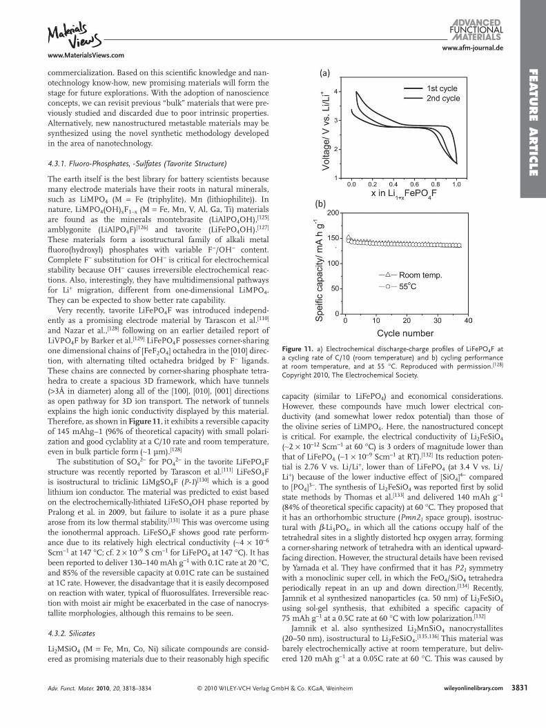
Figure 11 . a) Electrochemical discharge-charge profi les of LiFePO 4 F at a cycling rate of C/10 (room temperature) and b) cycling performance at room temperature, and at 55 ° C. Reproduced with permission. [ 128 ] Copyright 2010, The Electrochemical Society.
commercialization. Based on this scientifi c knowledge and nan-otechnology know-how, new promising materials will form the stage for future explorations. With the adoption of nanoscience concepts, we can revisit previous “bulk” materials that were pre-viously studied and discarded due to poor intrinsic properties. Alternatively, new nanostructured metastable materials may be synthesized using the novel synthetic methodology developed in the area of nanotechnology.
4.3.1. Fluoro-Phosphates, -Sulfates (Tavorite Structure)
The earth itself is the best library for battery scientists because many electrode materials have their roots in natural minerals, such as LiMPO 4 (M = Fe (triphylite), Mn (lithiophilite)). In nature, LiMPO 4 (OH) x F 1 − x (M = Fe, Mn, V, Al, Ga, Ti) materials are found as the minerals montebrasite (LiAlPO 4 OH), [ 125 ] amblygonite (LiAlPO 4 F) [ 126 ] and tavorite (LiFePO 4 OH). [ 127 ] These materials form a isostructural family of alkali metal fl uoro(hydroxyl) phosphates with variable F − /OH − content. Complete F − substitution for OH − is critical for electrochemical stability because OH − causes irreversible electrochemical reac-tions. Also, interestingly, they have multidimensional pathways for Li + migration, different from one-dimensional LiMPO 4 . They can be expected to show better rate capability.
Very recently, tavorite LiFePO 4 F was introduced independ-ently as a promising electrode material by Tarascon et al. [ 110 ] and Nazar et al., [ 128 ] following on an earlier detailed report of LiVPO 4 F by Barker et al. [ 129 ] LiFePO 4 F possesses corner-sharing one dimensional chains of [FeF 2 O 4 ] octahedra in the [010] direc-tion, with alternating tilted octahedra bridged by F − ligands. These chains are connected by corner-sharing phosphate tetra-hedra to create a spacious 3D framework, which have tunnels ( > 3Å in diameter) along all of the [ 100], [010], [001] directions as open pathway for 3D ion transport. The network of tunnels explains the high ionic conductivity displayed by this material. Therefore, as shown in Figure 11 , it exhibits a reversible capacity of 145 mAhg − 1 (96% of theoretical capacity) with small polari-zation and good cyclablity at a C/10 rate and room temperature, even in bulk particle form ( ∼ 1 µm). [ 128 ]
The substitution of SO 4 2 − for PO 4 2 − in the tavorite LiFePO 4 F structure was recently reported by Tarascon et al. [ 111 ] LiFeSO 4 F is isostructural to triclinic LiMgSO 4 F ( P-1 ) [ 130 ] which is a good lithium ion conductor. The material was predicted to exist based on the electrochemically-lithiated LiFeSO 4 OH phase reported by Pralong et al. in 2009, but failure to isolate it as a pure phase arose from its low thermal stability. [ 131 ] This was overcome using the ionothermal approach. LiFeSO 4 F shows good rate perform-ance due to its relatively high electrical conductivity ( ∼ 4 × 10 − 6 Scm − 1 at 147 ° C; cf. 2 × 10 − 9 S cm − 1 for LiFePO 4 at 147 ° C). It has been reported to deliver 130–140 mAh g − 1 with 0.1C rate at 20 ° C, and 85% of the reversible capacity at 0.01C rate can be sustained at 1C rate. However, the disadvantage that it is easily decomposed on reaction with water, typical of fl uorosulfates. Irreversible reac-tion with moist air might be exacerbated in the case of nanocrys-tallite morphologies, although this remains to be seen.
4.3.2. Silicates
Li 2 MSiO 4 (M = Fe, Mn, Co, Ni) silicate compounds are consid-ered as promising materials due to their reasonably high specifi c
© 2010 WILEY-VCH Verlag GAdv. Funct. Mater. 2010, 20, 3818–3834
capacity (similar to LiFePO 4 ) and economical considerations. However, these compounds have much lower electrical con-ductivity (and somewhat lower redox potential) than those of the olivine series of LiMPO 4 . Here, the nanostructured concept is critical. For example, the electrical conductivity of Li 2 FeSiO 4 ( ∼ 2 × 10 − 12 Scm − 1 at 60 ° C) is 3 orders of magnitude lower than that of LiFePO 4 ( ∼ 1 × 10 − 9 Scm − 1 at RT). [ 132 ] Its reduction poten-tial is 2.76 V vs. Li/Li + , lower than of LiFePO 4 (at 3.4 V vs. Li/Li + ) because of the lower inductive effect of [SiO 4 ] 4 − compared to [PO 4 ] 3 − . The synthesis of Li 2 FeSiO 4 was reported fi rst by solid state methods by Thomas et al. [ 133 ] and delivered 140 mAh g − 1 (84% of theoretical specifi c capacity) at 60 ° C. They proposed that it has an orthorhombic structure ( Pmn2 1 space group), isostruc-tural with β -Li 3 PO 4 , in which all the cations occupy half of the tetrahedral sites in a slightly distorted hcp oxygen array, forming a corner-sharing network of tetrahedra with an identical upward-facing direction. However, the structural details have been revised by Yamada et al. They have confi rmed that it has P2 1 symmetry with a monoclinic super cell, in which the FeO 4 /SiO 4 tetrahedra periodically repeat in an up and down direction. [ 134 ] Recently, Jamnik et al synthesized nanoparticles (ca. 50 nm) of Li 2 FeSiO 4 using sol-gel synthesis, that exhibited a specifi c capacity of 75 mAh g − 1 at a 0.5C rate at 60 ° C with low polarization. [ 132 ]
Jamnik et al. also synthesized Li 2 MnSiO 4 nanocrystallites (20–50 nm), isostructural to Li 2 FeSiO 4 . [ 135,136 ] This material was barely electrochemically active at room temperature, but deliv-ered 120 mAh g − 1 at a 0.05C rate at 60 ° C. This was caused by
mbH & Co. KGaA, Weinheim 3831wileyonlinelibrary.com
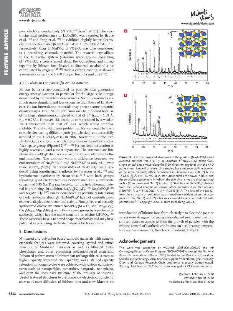
FEATU
RE
ARTI
CLE
3832
www.afm-journal.dewww.MaterialsViews.com
Figure 12 . XRD patterns and structures of the pristine (Na 2 FePO 4 F) and oxidized material (NaFePO 4 F). a) Structure of Na 2 FePO 4 F taken from single-crystal data shown along the [100] direction, together with the XRD pattern and Rietveld analysis of a single-phase microcrystalline powder of the same material; lattice parameters in Pbcn are a = 5.2200(2) Å, b = 13.8540(6) Å, c = 11.7792(5) Å. Iron octahedral are shown in blue, and the phosphate tetrahedra in yellow; the two alkali sites are distinguished as Na (1) in green and Na (2) in pink. b) Structure of NaFePO 4 F derived from the Rietveld analysis as shown; lattice parameters in Pbcn are a = 5.1047(9) Å, b = 14.1326(2) Å, c = 11.3655(1) Å. The loss of the Na (2) from the structure on oxidation was immediately evident when the occu-pancy of the Na (1) and (2) sites was allowed to vary. Reproduced with permission. [ 141 ] Copyright 2007, Nature Publishing Group.
poor electrical conductivity ( < 1 × 10 − 14 Scm − 1 at RT). The elec-trochemical performance of Li 2 CoSiO 4 was reported by Bruce et al. [ 137 ] and Yang et al. [ 138 ] It exhibited slightly better electro-chemical performance (60 mAh g − 1 at 50 ° C, 75 mAh g − 1 at 30 ° C, respectively) than Li 2 MnPO 4 . Li 2 VOSiO 4 was also considered to a promising electrode material. The material crystallizes in the tetragonal system ( P4/nmm space group), consisting of [VOSiO 4 ] n sheets stacked along the c-direction, and linked together by lithium ions located at distorted octahedral sites coordinated by oxygen. [ 139,140 ] With a carbon coating, it showed a reversible capacity of 0.5–0.6 Li per formula unit at 25 ° C.
4.3.3. Polyanion Compounds for Na Ion Batteries
Na ion batteries are considered as possible next generation energy storage systems, in particular for the large-scale storage demanded by renewable energy sources. Sodium resources are much more abundant and less expensive than those of Li. How-ever, Na ion intercalation materials may present some potential disadvantages. First, Na ion diffusion may be hindered because of its larger dimension compared to that of Li + (r Na + = 1.02 Å, r Li + = 0.76Å). However, this could be compensated by a weaker Na-O interaction than that of Li-O, which would improve mobility. The slow diffusion problem of Na ion could be over-come by decreasing diffusion path (particle size), as successfully adopted in the LiFePO 4 case. In 2007, Nazar et al. introduced Na 2 FePO 4 F, a compound which crystallizes in the orthorhombic Pbcn space group ( Figure 12 ). [ 141,142 ] Na ion de/intercalation is highly reversible, and almost topotactic. The intermediate line phase Na 1.5 FePO 4 F displays a structure almost identical to the end members. The unit cell volume difference between two end members of Na 2 FePO 4 F and NaFePO 4 F is only 4%, lower than LiFePO 4 (6.7%). Nanocrystallites of Na 2 FePO 4 F were pro-duced using ionothermal synthesis by Tarascon et al., [ 109 ] and hydrothermal synthesis by Nazar et al., [ 142 ] with both groups reporting good electrochemical performance and a reversible capacity of 0.85 Na. The rate behavior for the hydrothermal mate-rial is promising. In addition, Na 3 V 2 (PO 4 ) 2 F 3 , [ 143 ] Na 2 CoPO 4 F [ 144 ] and Na 2 MnPO 4 F [ 145 ] can be considered as potentially interesting cathode materials although Na 2 MnPO 4 F has not currently been shown to display electrochemical activity. Finally, Lee et al. recently synthesized olivine-structured NaMPO 4 (M = Fe, Mn, Mn 0.5 Fe 0.5 , Ca 0.2 Mn 0.8 , Mg 0.2 Mn 0.8 ) with Pnma space group by topochemical synthesis, which has the same structure as olivine LiFePO 4 . [ 146 ] These materials have a nanorod-shape morphology and may have potential as promising electrode materials for Na ion cells.
5. Conclusions
Mn-based and polyanion-based cathodic materials with nanom-eter-scale features were reviewed, covering layered and spinel structure of Mn-based materials as well as lithiated metal phosphates and other promising polyanion-based materials. Enhanced peformances of lithium ion rechargeable cells such as higher capacity, improved rate capability, and sustained capacity retention for longer cycles were achieved with various nanostruc-tures such as nanoparicles, nanotubes, nanorods, nanoplates, and even the secondary structure of the primary nano-units. Useful featured structures to overcome low electroic conductivity, slow solid-state diffusion of lithium ions and slow kinetics on
© 2010 WILEY-VCH Verlag Gwileyonlinelibrary.com
introduction of lithium ions from electrolyte to electrode (or vice versa) were designed by using nano-shaped precursors, hard or soft templates or agents to limit the growth of paricles with the minute control of synthetic conditions such as heating tempera-ture and environments, the choice of solvent, and pH.
Acknowledgements This work was supported by WCU/R31–2008-000–20012-0 and the Converging Research Center Program (2009–0082083) through the National Research Foundation of Korea (NRF) funded by the Ministry of Education, Science and Technology. Also, fi nancial support from NSERC (the Discovery Grant and Canada Research Chair programs) is greatly acknowledged. Pohang Light Sources (PLS) is also acknowledged for XAS measurements
Received: February 4, 2010Revised: April 20, 2010
Published online: October 5, 2010
mbH & Co. KGaA, Weinheim Adv. Funct. Mater. 2010, 20, 3818–3834

FEATU
RE A
RTIC
LE
www.afm-journal.dewww.MaterialsViews.com
[ 1 ] Z. Lu , D. D. MacNeil , J. R. Dahn , Electrochem. Solid-State Lett. 2001 , 4 , A191 .
[ 2 ] Z. H. Lu , L. Y. Beaulieu , R. A. Donaberger , C. L. Thomas , J. R. Dahn , J. Electrochem. Soc. 2002 , 149 , A778 .
[ 3 ] Z. H. Lu , J. R. Dahn , J. Electrochem. Soc. 2002 , 149 , A1454 . [ 4 ] Z. Lu , D. D. MacNeil , J. R. Dahn , Electrochem. Solid-State Lett.
2001 , 4 , A200 . [ 5 ] D. D. MacNeil , Z. Lu , J. R. Dahn , J. Electrochem. Soc. 2002 , 149 ,
A1332 . [ 6 ] B. Ammundsen , J. Paulsen , Adv. Mater. 2001 , 13 , 943 . [ 7 ] J. Cho , B. Park , Electrochem. Solid-State Lett. 2000 , 3 , 355 . [ 8 ] Y. J. Park , Y. S. Hong , X. L. Wu , M. G. Kim , K. S. Ryu , S. H. Chang ,
J. Electrochem. Soc. 2004 , 151 , A720 . [ 9 ] M. M. Thackeray , Prog. Solid State Chem. 1997 , 25 , 1 . [ 10 ] A. Blyr , C. Sigala , G. Amatucci , D. Guyomard , Y. Chabre ,
J. M. Tarascon , J. Electrochem. Soc. 1998 , 145 , 194 . [ 11 ] R. J. Gummow , A. Dekock , M. M. Thackeray , Solid State Ionics
1994 , 69 , 59 . [ 12 ] Y. Xia , M. Yoshio , Lithium Batteries Science and Technology (Eds.:
G.-A. Nazri , G.-A. Pistoia ), Kluwer , Boston 2004 , 361 . [ 13 ] J. Cho , Y. J. Kim , B. Park , Solid State Ionics 2001 , 138 , 221 . [ 14 ] M. Wakihara , G. Li , H. Ikuta , Lithium Batteries Fundmentals and
Performance (Eds.: M. Wakihara , O. Yamamoto ), Kodansha , Japanand Wiley-VCH , Germany 1998 , p. 26 .
[ 15 ] A. Manthiram , A. Murugan , A. Sarkar , T. Muraliganth , EnergyEnviron. Sci. 2008 , 1 , 621 .
[ 16 ] A. K. Padhi , K. S. Nanjundaswamy , J. B. Goodenough , J. Electro-chem. Soc. 1997 , 144 , 1188 .
[ 17 ] J. Eom , K. S. Ryu , J. Cho , J. Electrochem. Soc. 2008 , 155 , A228 . [ 18 ] Y. Kim , J. Eom , M. G. Kim , Y. K. Sun , C. S. Yoon , J. P. Cho ,
J. Electrochem. Soc. 2007 , 154 , A561 . [ 19 ] Y. Cho , J. Cho , J. Electrochem. Soc. 2010 , 157 , A625 . [ 20 ] J. Cho , G. Kim , H. S. Lim , J. Electrochem. Soc. 1999 , 146 , 3571 . [ 21 ] P. G. Bruce , B. Scrosati , J. M. Tarascon , Angew. Chem. Int. Ed.
2008 , 47 , 2930 . [ 22 ] M. Winter , R. J. Brodd , Chem. Rev. 2004 , 104 , 4245 . [ 23 ] S. Lee , J. Cho , Chem. Commu. 2010 , 2444 . [ 24 ] M. G. Kim , J. Cho , Adv. Funct. Mater. 2009 , 19 , 1497 . [ 25 ] D. Deng , M. G. Kim , J. Y. Lee , J. Cho , Energy Environ. Sci. 2009 , 2 , 818 . [ 26 ] C. Fouassier , C. Delmas , P. Hagenmuller , Mater. Res. Bull. 1975 ,
10 , 443 . [ 27 ] F. Leroux , D. Guyomard , Y. Piffard , Solid State Ionics 1995 , 80 , 299 . [ 28 ] F. Capitaine , P. Gravereau , C. Delmas , Solid State Ionics 1996 , 89 , 197 . [ 29 ] P. G. Bruce , A. R. Armstrong , R. L. Gitzendanner , J. Mater. Chem.
1999 , 9 , 193 . [ 30 ] R. Chen , P. Zavalij , M. S. Whittingham , Chem. Mater. 1996 , 8 , 1275 . [ 31 ] S. Ching , D. J. Petrovay , M. L. Jorgensen , S. L. Suib , Inorg. Chem.
1997 , 36 , 883 . [ 32 ] S. Ching , J. A. Landrigan , M. L. Jorgensen , N. G. Duan , S. L. Suib ,
C. L. Oyoung , Chem. Mater. 1995 , 7 , 1604 . [ 33 ] P. LeGoff , N. Baffi er , S. Bach , J. P. PereiraRamos , Mater. Res. Bull.
1996 , 31 , 63 . [ 34 ] Y. F. Shen , S. L. Suib , C. L. Oyoung , J. Am. Chem. Soc. 1994 , 116 ,
11020 . [ 35 ] A. R. Armstrong , M. Holzapfel , P. Novak , C. S. Johnson , S. H. Kang ,
M. M. Thackeray , P. G. Bruce , J. Am. Chem. Soc. 2006 , 128 , 8694 . [ 36 ] Y. S. Hong , Y. J. Park , K. S. Ryu , S. H. Chang , M. G. Kim , J. Mater.
Chem. 2004 , 14 , 1424 . [ 37 ] J. Cho , Y. Kim , M. G. Kim , J. Phys. Chem. C 2007 , 111 , 3192 . [ 38 ] M. G. Kim , M. Jo , Y. S. Hong , J. Cho , Chem. Commun. 2009 , 218 . [ 39 ] Y. Kim , Y. Hong , M. G. Kim , J. Cho , Electrochem. Commun. 2007 , 9 ,
1041 . [ 40 ] I.V. Markov , Crystal Growth for Beginners, Fundamentals of Nuclea-
tion, Crystal Growth and Epitaxy, 1st ed., World Scientifi c PublishingCo ., River Edge, NJ 1995 .
© 2010 WILEY-VCH Verlag GmAdv. Funct. Mater. 2010, 20, 3818–3834
[ 41 ] Y. J. Lee , M. G. Kim , J. Cho , Nano Lett. 2008 , 8 , 957 . [ 42 ] M. Balasubramanian , J. McBreen , I. J. Davidson , P. S. Whitfi eld ,
I. Kargina , J. Electrochem. Soc. 2002 , 149 , A176 . [ 43 ] L. H. Yu , H. X. Yang , X. P. Ai , Y. L. Cao , J. Phys. Chem. B 2005 , 109 ,
1148 . [ 44 ] M. Jo , Y. Lee , K. Kim , J. Cho , J. Electrochem. Soc. 20 10 , 157 , A841 . [ 45 ] D. K. Kim , P. Muralidharan , H. W. Lee , R. Ruffo , Y. Yang ,
C. K. Chan , H. Peng , R. A. Huggins , Y. Cui , Nano Lett. 2008 , 8 , 3948 . [ 46 ] J. M. Tarascon , E. Wang , F. K. Shokoohi , W. R. Mckinnon ,
S. Colson , J. Electrochem. Soc. 1991 , 138 , 2859 . [ 47 ] V. G. Kumar , J. S. Gnanaraj , S. Ben-David , D. M. Pickup ,
E. R. H. Van-Eck , A. Gedanken , D. Aurbach , Chem. Mater. 2003 , 15 , 4211 .
[ 48 ] M. Nishizawa , K. Mukai , S. Kuwabata , C. R. Martin , H. Yoneyama , J. Electrochem. Soc. 1997 , 144 , 1923 .
[ 49 ] X. X. Li , F. Y. Cheng , B. Guo , J. Chen , J. Phys. Chem. B 2005 , 109 , 14017 .
[ 50 ] L. Z. Zhang , J. C. Yu , A. W. Xu , Q. Li , K. W. Kwong , L. Wu , Chem. Commun. 2003 , 2910 .
[ 51 ] E. Hosono , T. Kudo , I. Honma , H. Matsuda , H. S. Zhou , Nano Lett. 2009 , 9 , 1045 .
[ 52 ] F. Jiao , J. L. Bao , A. H. Hill , P. G. Bruce , Angew. Chem. Int. Ed. 2008 , 47 , 9711 .
[ 53 ] J.-Y. Luo , Y.-G. Wang , H.-M. Xiong , Y.-Y. Xia , Chem. Mater. 2007 , 19 , 4791 .
[ 54 ] K. M. Shaju , P. G. Bruce , Chem. Mater. 2008 , 20 , 5557 . [ 55 ] D. Tonti , M. J. Torralvo , E. Enciso , I. Sobrados , J. Sanz , Chem.
Mater. 2008 , 20 , 4783 . [ 56 ] D. Aurbach , Y. Gofer , J. Electrochem. Soc. 1991 , 138 , 3529 . [ 57 ] D. Aurbach , A. Zaban , A. Schechter , Y. Eineli , E. Zinigrad ,
B. Markovsky , J. Electrochem. Soc. 1995 , 142 , 2873 . [ 58 ] G. G. Amatucci , A. Blyr , C. Sigala , P. Alfonse , J. M. Tarascon ,
Solid State Ionics 1997 , 104 , 13 . [ 59 ] J. Cho , T. J. Kim , Y. J. Kim , B. Park , Chem. Commun. 2001 , 1074 . [ 60 ] J. M. Han , S. T. Myung , Y. K. Sun , J. Electrochem. Soc. 2006 , 153 ,
A1290 . [ 61 ] Q. Cao , H. P. Zhang , G. J. Wang , Q. Xia , Y. P. Wu , H. Q. Wu ,
Electrochem. Commun. 2007 , 9 , 1228 . [ 62 ] C. Li , H. P. Zhang , L. J. Fu , H. Liu , Y. P. Wu , E. Ram , R. Holze ,
H. Q. Wu , Electrochim. Acta 2006 , 51 , 3872 . [ 63 ] J. W. Fergus , J. Power Sources 2010 , 195 , 939 . [ 64 ] S. Lim , J. Cho , Electrochem. Commun. 2008 , 10 , 1478 . [ 65 ] S. Lim , J. Cho , Chem. Commun. 2008 , 4472 . [ 66 ] J. Cho , J. Mater. Chem. 2008 , 18 , 2257 . [ 67 ] H. F. Wang , Y. I. Jang , Y. M. Chiang , Electrochem. Solid-State Lett.
1999 , 2 , 490 . [ 68 ] H. Kim , J. Cho , Chem. Mater. 2008 , 20 , 1679 . [ 69 ] H. Kim , J. Cho , J. Mater. Chem. 2008 , 18 , 771 . [70] N. Ravet , S. Besner , M. Simoneau , A. Vallee , M. Armand ,
J. F. Magnan , US Patent Application 2002, 20020195591 . [ 71 ] N. Ravet , Y. Chouinard , J. F. Magnan , S. Besner , M. Gauthier ,
M. Armand , J. Power Sources 2001 , 97–8 , 503 . [ 72 ] H. Huang , S. C. Yin , L. F. Nazar , Electrochem. Solid-State Lett.
2001 , 4 , A170 . [ 73 ] G. Kobayashi , S. I. Nishimura , M. S. Park , R. Kanno , M. Yashima ,
T. Ida , A. Yamada , Adv. Funct. Mater. 2009 , 19 , 395 . [ 74 ] S. K. Martha , J. Grinblat , O. Haik , E. Zinigrad , T. Drezen ,
J. H. Miners , I. Exnar , A. Kay , B. Markovsky , D. Aurbach , Angew. Chem. Int. Ed. 2009 , 48 , 8559 .
[ 75 ] Y. G. Wang , Y. R. Wang , E. J. Hosono , K. X. Wang , H. S. Zhou , Angew. Chem. Int. Ed. 2008 , 47 , 7461 .
[ 76 ] B. Kang , G. Ceder , Nature 2009 , 458 , 190 . [ 77 ] A. Kayyar , H. J. Qian , J. Luo , Appl. Phys. Lett. 2009 , 95 , 221905 . [ 78 ] G. Arnold , J. Garche , R. Hemmer , S. Strobele , C. Vogler ,
A. Wohlfahrt-Mehrens , J. Power Sources 2003 , 119 , 247 .
bH & Co. KGaA, Weinheim 3833wileyonlinelibrary.com
FEATU
RE
ARTI
CLE
3834
www.afm-journal.dewww.MaterialsViews.com
[ 79 ] J. J. Chen , M. S. Whittingham , Electrochem. Commun. 2006 , 8 , 855 . [ 80 ] G. Meligrana , C. Gerbaldi , A. Tuel , S. Bodoardo , N. Penazzi ,
J. Power Sources 2006 , 160 , 516 . [ 81 ] K. Shiraishi , K. Dokko , K. Kanamura , J. Power Sources 2005 , 146 , 555 . [ 82 ] X. Ou , S. Z. Xu , G. C. Liang , L. Wang , X. Zhao , Sci. China, Ser. E:
Technol. Sci. 2009 , 52 , 264 . [ 83 ] M. H. Lee , J. Y. Kim , H.-K. Song , Chem. Commun. 2010 , 46 , 6795. [ 84 ] N. V. Belov , E. N. Matvienko , A. N. Ivashchenko , O. V. Yakubovich ,
O. K. Mel’nikov , M. A. Simonov , Mineralogicheskii Zhurnal 1981 , 3 , 56 .
[ 85 ] S. F. Yang , P. Y. Zavalij , M. S. Whittingham , Electrochem. Commun. 2001 , 3 , 505 .
[ 86 ] J. Chen , S. Wang , M. S. Whittingham , J. Power Sources 2007 , 174 , 442 . [ 87 ] J. J. Chen , M. J. Vacchio , S. J. Wang , N. Chernova , P. Y. Zavalij ,
M. S. Whittingham , Solid State Ionics 2008 , 178 , 1676 . [ 88 ] G. Y. Chen , X. Y. Song , T. J. Richardson , Electrochem. Solid-State
Lett. 2006 , 9 , A295 . [ 89 ] D. Morgan , A. Van Der Ven , G. Ceder , Electrochem. Solid-State Lett.
2004 , 7 , A30 . [ 90 ] B. Ellis , W. H. Kan , W. R. M. Makahnouk , L. F. Nazar , J. Mater.
Chem. 2007 , 17 , 3248 . [ 91 ] M. Gauthier , Plug-in Hybrid and Electric Vehicle Conference , 2009 . [ 92 ] A. V. Murugan , T. Muraliganth , A. Manthiram , Electrochem.
Commun. 2008 , 10 , 903 . [ 93 ] A. V. Murugan , T. Muraliganth , A. Manthiram , J. Phys. Chem. C
2008 , 112 , 14665 . [ 94 ] A. V. Murugan , T. Muraliganth , P. J. Ferreira , A. Manthiram , Inorg.
Chem. 2009 , 48 , 946 . [ 95 ] D. H. Kim , J. Kim , Electrochem. Solid-State Lett. 2006 , 9 , A439 . [ 96 ] T. Drezen , N. H. Kwon , P. Bowen , I. Teerlinck , M. Isono , I. Exnar ,
J. Power Sources 2007 , 174 , 949 . [ 97 ] K. S. Park , K. T. Kang , S. B. Lee , G. Y. Kim , Y. J. Park , H. G. Kim ,
Mater. Res. Bull. 2004 , 39 , 1803 . [ 98 ] D. Choi , P. N. Kumta , J. Power Sources 2007 , 163 , 1064 . [ 99 ] C. Delacourt , P. Poizot , M. Morcrette , J. M. Tarascon , C. Masquelier ,
Chem. Mater. 2004 , 16 , 93 . [ 100 ] C. Delacourt , C. Wurm , P. Reale , M. Morcrette , C. Masquelier ,
Solid State Ionics 2004 , 173 , 113 . [ 101 ] C. Delacourt , P. Poizot , S. Levasseur , C. Masquelier , Electrochem.
Solid-State Lett. 2006 , 9 , A352 . [ 102 ] P. Gibot , M. Casas-Cabanas , L. Laffont , S. Levasseur , P. Carlach ,
S. Hamelet , J. M. Tarascon , C. Masquelier , Nat. Mater. 2008 , 7 , 741 .
[ 103 ] D. H. Kim , J. S. Kim , J. W. Kang , E. J. Kim , H. Y. Ahn , J. Kim , J. Nanosci. Nanotechnol. 2007 , 7 , 3949 .
[ 104 ] T. R. Kim , D. H. Kim , H. W. Ryu , J. H. Moon , J. H. Lee , S. Boo , J. Kim , J. Phys. Chem. Solids 2007 , 68 , 1203 .
[ 105 ] K. T. Lee , W. H. Kan , L. F. Nazar , J. Am. Chem. Soc. 2009 , 131 , 6044 . [ 106 ] S. K. Martha , B. Markovsky , J. Grinblat , Y. Gofer , O. Haik ,
E. Zinigrad , D. Aurbach , T. Drezen , D. Wang , G. Deghenghi , I. Exnar , J. Electrochem. Soc. 2009 , 156 , A541 .
[ 107 ] D. Y. Wang , H. Buqa , M. Crouzet , G. Deghenghi , T. Drezen , I. Exnar , N. H. Kwon , J. H. Miners , L. Poletto , M. Graetzel , J. Power Sources 2009 , 189 , 624 .
[ 108 ] N. Recham , L. Dupont , M. Courty , K. Djellab , D. Larcher , M. Armand , J. M. Tarascon , Chem. Mater. 2009 , 21 , 1096 .
[ 109 ] N. Recham , J. N. Chotard , L. Dupont , K. Djellab , M. Armand , J. M. Tarascon , J. Electrochem. Soc. 2009 , 156 , A993 .
[ 110 ] N. Recham , J. N. Chotard , J. C. Jumas , L. Laffont , M. Armand , J. M. Tarascon , Chem. Mater. 2010 , 22 , 1142 .
[ 111 ] N. Recham , J. N. Chotard , L. Dupont , C. Delacourt , W. Walker , M. Armand , J. M. Tarascon , Nat. Mater. 2010 , 9 , 68 .
[ 112 ] J. M. Tarascon , N. Recham , M. Armand , J. N. Chotard , P. Barpanda , W. Walker , L. Dupont , Chem. Mater. 2010 , 22 , 724 .
© 2010 WILEY-VCH Verlag Gwileyonlinelibrary.com
[ 113 ] X. F. Guo , W. P. Ding , X. G. Wang , Q. J. Yan , Chem. Commun. 2001 , 709 .
[ 114 ] B. Z. Tian , X. Y. Liu , B. Tu , C. Z. Yu , J. Fan , L. M. Wang , S. H. Xie , G. D. Stucky , D. Y. Zhao , Nat. Mater. 2003 , 2 , 159 .
[ 115 ] A. Bhaumik , S. Inagaki , J. Am. Chem. Soc. 2001 , 123 , 691 . [ 116 ] S. M. Zhu , H. S. Zhou , T. Miyoshi , M. Hibino , I. Honma ,
M. Ichihara , Adv. Mater. 2004 , 16 , 2012 . [ 117 ] S. Lim , C. S. Yoon , J. Cho , Chem. Mater. 2008 , 20 , 4560 . [ 118 ] M. Gaberscek , R. Dominko , J. Jamnik , Electrochem. Commun. 2007 ,
9 , 2778 . [ 119 ] A. Yamada , H. Koizumi , S. I. Nishimura , N. Sonoyama , R. Kanno ,
M. Yonemura , T. Nakamura , Y. Kobayashi , Nat. Mater. 2006 , 5 , 357 . [ 120 ] C. Delacourt , P. Poizot , J. M. Tarascon , C. Masquelier , Nat. Mater.
2005 , 4 , 254 . [ 121 ] L. Laffont , C. Delacourt , P. Gibot , M. Y. Wu , P. Kooyman ,
C. Masquelier , J. M. Tarascon , Chem. Mater. 2006 , 18 , 5520 . [ 122 ] C. Delmas , M. Maccario , L. Croguennec , F. Le Cras , F. Weill ,
Nat. Mater. 2008 , 7 , 665 . [ 123 ] J. F. Martin , A. Yamada , G. Kobayashi , S. I. Nishimura , R. Kanno ,
D. Guyomard , N. Dupre , Electrochem. Solid-State Lett. 2008 , 11 , A12 . [ 124 ] S. Hamelet , P. Gibot , M. Casas-Cabanas , D. Bonnin , C. P. Grey ,
J. Cabana , J. B. Leriche , J. Rodriguez-Carvajal , M. Courty , S. Levasseur , P. Carlach , M. van Thournout , J. M. Tarascon , C. Masquelier , J. Mater. Chem. 2009 , 19 , 3979 .
[ 125 ] W. H. Baur , Beitr. Mineral. Petrol. 1959 , 6 , 399 . [ 126 ] V. I. Simonov , N. V. Belov , Krist. 1958 , 3 , 429 . [ 127 ] A. C. Roberts , P. J. Dunn , J. D. Grice , D. E. Newbury , E. Dale ,
W. L. Roberts , Powder Diffr. 1988 , 3 , 93 . [ 128 ] T. N. Ramesh , K. T. Lee , B. Ellis , L. F. Nazar , Electrochem.
Solid-State Lett. 2010 , 13 , A43 . [ 129 ] J. Barker , M. Y. Saidi , J. L. Swoyer , J. Electrochem. Soc. 2003 , 150 ,
A1394 . [ 130 ] L. Sebastian , J. Gopalakrishnan , Y. Piffard , J. Mater. Chem. 2002 ,
12 , 374 . [ 131 ] M. A. Reddy , V. Pralong , V. Caignaert , U. V. Varadaraju , B. Raveau ,
Electrochem. Commun. 2009 , 11 , 1807 . [ 132 ] R. Dominko , D. E. Conte , D. Hanzel , M. Gaberscek , J. Jamnik ,
J. Power Sources 2008 , 178 , 842 . [ 133 ] A. Nyten , S. Kamali , L. Haggstrom , T. Gustafsson , J. O. Thomas ,
J. Mater. Chem. 2006 , 16 , 2266 . [ 134 ] S. I. Nishimura , S. Hayase , R. Kanno , M. Yashima , N. Nakayama ,
A. Yamada , J. Am. Chem. Soc. 2008 , 130 , 13212 . [ 135 ] R. Dominko , M. Bele , A. Kokalj , M. Gaberscek , J. Jamnik , J. Power
Sources 2007 , 174 , 457 . [ 136 ] A. Kokalj , R. Dominko , G. Mali , A. Meden , M. Gaberscek , J. Jamnik ,
Chem. Mater. 2007 , 19 , 3633 . [ 137 ] C. Lyness , B. Delobel , A. R. Armstrong , P. G. Bruce , Chem.
Commun. 2007 , 4890 . [ 138 ] Z. L. Gong , Y. X. Li , Y. Yang , J. Power Sources 2007 , 174 , 524 . [ 139 ] A. S. Prakash , P. Rozier , L. Dupont , H. Vezin , F. Sauvage ,
J. M. Tarascon , Chem. Mater. 2006 , 18 , 407 . [ 140 ] M. Dompablo , P. Rozier , M. Morcrette , J. M. Tarascon , Chem.
Mater. 2007 , 19 , 2411 . [ 141 ] B. L. Ellis , W. R. M. Makahnouk , Y. Makimura , K. Toghill ,
L. F. Nazar , Nat. Mater. 2007 , 6 , 749 . [ 142 ] B. Ellis , W. R. M. Makahnouk , W. N. Rowan-Weetaluktuk ,
D. H. Ryan , L. F. Nazar , Chem. Mater. 2010 , 22 , 1059 . [ 143 ] J. Barker , R. K. B. Gover , P. Burns , A. J. Bryan , Electrochem.
Solid-State Lett. 2006 , 9 , A190 . [ 144 ] F. Sanz , C. Parada , C. Ruiz-Valero , J. Mater. Chem. 2001 , 11 , 208 . [ 145 ] O. V. Yakubovich , O. V. Karimova , O. K. Melnikov , Acta Crystallogr.,
Sect. C: Cryst. Struct. Commun. 1997 , 53 , 395 . [146 ] K. T. Lee , T. N. Ramesh , W. H. Kan , H. W. Park , B. Ellis , F . Nan ,
G. Botton , L. F. Nazar , unpublished.
mbH & Co. KGaA, Weinheim Adv. Funct. Mater. 2010, 20, 3818–3834