Adson Thumb Forceps for use in Challenging · PDF fileAdson Thumb Forceps for use in...
62
Adson Thumb Forceps for use in Challenging Conditions Michigan State University ECE 480 – Design Team 1 Spring 2015 Project Sponsor: Dr. Satish Udpa Project Facilitator: Dr. Wen Li Team Members: Adam Stowe Jose Carmona Kasey Durkin Parker Mojsiejenko Stephanie Le
Transcript of Adson Thumb Forceps for use in Challenging · PDF fileAdson Thumb Forceps for use in...

Adson Thumb Forceps for use in Challenging Conditions
Michigan State University
ECE 480 – Design Team 1
Spring 2015
Project Sponsor:
Dr. Satish Udpa
Project Facilitator:
Dr. Wen Li
Team Members:
Adam Stowe
Jose Carmona
Kasey Durkin
Parker Mojsiejenko
Stephanie Le

2
Acknowledgments
Dr. Satish Udpa: As the sponsor for the project from Michigan State University College of
Engineering, Dr. Udpa provided an exceptional project allowing us to make an impact on
improving the health and safety of patients in underdeveloped countries. We truly appreciate all
the time spent meeting with the group to discuss specifications, various design ideas and
progression of the project.
Dr. Wen Li: As the faculty facilitator, Dr. Li assisted by providing the team with guidance and
feedback while completing project deliverables. Her positive attitude translated to the group
members allowing us to successfully collaborate and remain focused as a team.
Dr. Timothy Grotjohn, Dr. Lalita Udpa, and all guest speakers during Spring, 2015: We would
like to thank the above individuals for all the knowledge shared throughout the semester. This
information helped us throughout the semester and will continue to be utilized within our
professional careers.
MSU ECE Shop and Mrs. Roxanne Peacock: Thank you for your continued assistance
throughout the semester by supplying the necessary equipment and obtaining project materials in
a timely manner.
Dr. Helene Pazak and the MSU College of Veterinary Medicine: Dr. Pazak and her staff
provided vital information which was utilized in the design of the project. Their assistance and
feedback allowed the team to create a low cost self-suffusing surgical tool system.

3
Executive Summary
Surgical environments in developing countries lack the proper sanitization practices
causing an increase in infections experienced by a patient. This can lead to extended recovery
times, and often an increase in mortality rates. The development of a surgical tool capable of
remaining sterile throughout a surgery in these challenging settings is currently unavailable in
the market.
The goal of this project is to create Adson thumb forceps capable of suffusing
antimicrobials continuously throughout a surgery to help improve the sanitization of the tool and
reduce surgical infections experienced by a patient. An air compressor powered by a battery will
inflate a pressure bag encasing an IV bag containing the antimicrobial. It will be transported to
the Adson thumb forceps with tubing and utilize micro-channels to deliver the desired fluid to
the surface of the tool. The tool will be capable of functioning for a minimum of six hours and
will be able to run for the duration of the surgery, minimizing the growth of bacteria. This
project can reduce patient recovery times along with reducing mortality rates caused by
unsanitary surgical settings.

4
Table of Contents
Chapter 1- Introduction ……………………………………………………………………….. 6
1.1 Project Description ………………………………………………………………...… 6
1.2 Project Solution ……………………………………………………………………… 6
1.3 Background ………………………………………………………………………….. 6
Chapter 2 – Project Design Overview ………………………………………………………… 8
2.1 Proposed Solutions ………………………………………………………………….. 8
2.1.1 Design One ………………………………………………………………… 8
2.1.2 Design Two …………………………………………………………….….. 8
2.2 RFD22102 RFDuino Dip ……………………………………………………………. 9
2.3 FAST Diagram …………………………………………………………………...… 11
2.4 Gantt Chart …………………………………………………………………………. 11
2.5 Budget ……………………………………………………………………………… 14
2.6 House of Quality …………………………………………………………………… 15
Chapter 3 – Technical Description …………………………………………………………... 16
3.1 Power Supply ………………………………………………………………………. 16
3.2 Microcontroller Hardware …………………………………………………………. 17
3.3 Microcontroller Software …………………………………………………………... 18
3.4 Integration of Android Application ………………………………………………... 21
3.5 Microchannel Forceps Design ……………………………………………………... 24
Chapter 4 – Test Data ………………………………………………………………………… 26
4.1 Manual Testing …………………………………………………………………….. 26
4.1.1 Suffusion Due to Pressure ………………………………………………... 26
4.1.2 Pressure Drop Related to Time and Fluid Suffused ……………………… 27
4.2 Testing of Current ………………………………………………………………….. 28
4.3 Power Consumption ………………………………………………………………... 29
4.4 Additional Testing …………………………………………………………………. 30
Chapter 5 – Surgical Tool: Final System Integration ………………………………………. 31
5.1 Summary ………………………………………………………………………….... 31
5.2 Budget Management ……………………………………………………………….. 32
5.3 Time Management …………………………………………………………………. 33

5
5.4 Lessons Learned ……………………………………………………………………. 33
5.5 Future Improvements ………………………………………………………………. 34
5.5.1 Continuously Powered Pump ……………………………………………. 34
5.5.2 Bluetooth Controlled Sensor ……………………………………………... 34
5.5.3 Multi-Tool System ……………………………………………………….. 34
5.5.4 Modifications Suggested by MSU College of Veterinary Medicine …….. 35
Chapter 6 – Appendix 1 ………………………………………………………………………. 36
6.1 Technical and Non-Technical Roles and Responsibilities …………………………. 36
6.1.1 Adam Stowe ……………………………………………………………… 37
6.1.2 Jose Carmona …………………………………………………………….. 37
6.1.3 Kasey Durkin …………………………………………………………….. 38
6.1.4 Parker Mojsiejenko ………………………………………………………. 38
6.1.5 Stephanie Le ……………………………………………………………… 39
Chapter 7 – Appendix 2 ………………………………………………………………………. 40
7.1 References ………………………………………………………………………….. 40
Chapter 8 – Appendix 3 ………………………………………………………………………. 41
8.1 Project Block Diagram ……………………………………………………………... 41
8.2 Component Images ……………………………………………………………….... 42
8.3 Adson Thumb Forceps Schematics ………………………………………………… 45
8.4 Source Code ………………………………………………………………………... 48
8.4.1 RFduino Code ……………………………………………………………. 48
8.4.2 Android Code …………………………………………………………….. 50
8.4.3 RFduino Service ………………………………………………………….. 57
8.5 Power Consumption Calculations …………………………………………………. 62
8.6 Links to Data Sheets ……………………………………………………………….. 62

6
Chapter 1 - Introduction
1.1 Project Description
The task presented to the group was to create a surgical tool capable of continuous
suffusion of an antimicrobial. This new class of surgical tool would be especially useful in
underdeveloped countries where sufficient health care and sanitary surgical settings are nearly
nonexistent. The suggested surgical tool to be used was forceps, however the final decision was
left to the group. The tool needed to interface with a smartphone application which would
control the amount of antimicrobial supplied to the tool. The constraints include a battery
capable of lasting the duration of a six hour surgery and continuous suffusion of the tool for a
minimum of three hours.
1.2 Project Solution
The solution for this project devised by the team is to develop Adson thumb forceps
which are capable of continuously suffusing antimicrobials, increasing the cleanliness of the
surface of the tool. This will be implemented through creating microchannels within the tool to
transport the antimicrobial. Once the device is designed, it can be created through the use of an
advanced 3D printer. The antimicrobial selected is chlorhexidine which will be transported to
the thumb forceps through tubes connected to a typical saline bag commonly found within the
medical field. The saline bag containing the correct concentration of chlorhexidine is surrounded
by a pressure bag. An air compressor will supply an increase in pressure which will then cause
the antimicrobial to be transported and suffuse the tool. Algorithms will be calculated to
determine the correct flow rate of the fluid from the bag to disinfect the entire surface of the tool
for the required period of time. The successful completion of this improved surgical tool can
help reduce the occurrence of surgical site infections within patients in unsanitary operating
settings and ultimately save lives.
1.3 Background
Surgical Site Infections (SSI) occur at the location where the surgery was performed and
can be a result of unsanitary surgical settings and practices. These infections can lead to extended
hospitalization, treatment, and even death. In a study conducted by the Center for Disease
Control (CDC) in the United States from 2006-2008, there were over 16,000 surgical site

7
infections which equated to an overall rate of 1.9% of all operative procedures. However, the
prevalence of these infections drastically increases when compared with underdeveloped
countries. A similar study conducted in India in 2007 showed 21.6% of patients suffered from
surgical site infections. The infection control practices such as sterilization methods, operating
room ventilation, and availability of antimicrobials in these countries are not comparable to that
of the United States.
The current methods of sanitization of surgical tools are performed prior to the surgery
allowing time for the tool to become unsanitary before contact with a patient. These approaches
include mechanical or automatic devices such as ultrasonic cleaners or washer-disinfectors,
however these machines are not available in underdeveloped countries. Therefore the most
common procedure used in these areas of the world is simply manually cleaning the surgical
tools. In addition, the settings of operating rooms do not consist of a fully sterile environment.
As a result any time a tool is placed on a surface in the room, it becomes susceptible to the
surrounding bacteria. Since the proposed project solution consists of a constant suffusion of
antimicrobial, it eliminates any time for bacteria to collect on the surgical tool.

8
Chapter 2 - Project Design Overview
2.1 Proposed Solutions
The team developed two design options, each utilizing different methods of
antimicrobial delivery to the surgical tool. The proposed designs are described below.
2.1.1 Design One
The use of a micropump was the key factor in the initial proposed idea. This was part of
the idea originally mentioned by the team’s project sponsor, Dr. Satish Udpa. The lithium-ion
battery would be connected by wire to the circuit board and would function as the voltage input
for the circuit. The power would then be stepped down and connected to the microcontroller to
supply power. The other output would be used to power the micropump and then be connected
back to ground in the circuit. The micropump, with the container of the diluted fluid, pumps the
fluid into the tubing. The tubing then flows into the microchannels and eventually to the surface
of the tool. A sensor detects the flow at the end of the tubing before the microchannel and inputs
the data into it and adjusts the micropump on how much pressure to use.
2.1.2 Design Two
The second design idea was inspired by the information gathered on a trip to the
Michigan State University College of Veterinary Medicine. Because the cost of procedures on
animals is all out of pocket payment by the owners, veterinarians work to keep costs low. This
principle is also important to implement when creating a surgical tool to be used in
underdeveloped countries. Many patients lack the necessary money to pay for sufficient health
care and often must undergo vital surgeries in unsanitary surgical settings.
This design would use the same initial setup with the battery and the battery circuit
powering the pump and the microcontroller. However in this case, an air pump would be used to
inflate a pressure bag. Any type of air pump can be used as long as it is able to be connected to
the programmed microcontroller and the pressure bag. The pressure bag will apply force on the
IV bag filled with the diluted solution. This will force the solution into the tubing, through the
microchannels and finally to the surface of the tool. A desired pressure will be necessary in the
surgical room in order to achieve the correct flow rate. This will be set with the microcontroller

9
that will input the signal to the air pump. It will tell the pressure bag when to inflate to add more
air and when to deflate to reduce the pressure.
The solution design matrix below shows the comparison of these two methods of
delivering the antimicrobial to the surface of the tool. There were also two different types of
surgical tools being analyzed for creation within the SolidWorks software. These consisted of a
Lancet scalpel or Adson thumb forceps. One of the disadvantages associated with the scalpel is
that both the tip and the edge of the blade are used throughout a surgery. This means the
suffusion of the blade would be difficult to ensure.
Table 1 - Solution Design Matrix
As shown in the matrix above, the design with the Adson thumb forceps which utilizes
the IV bag surrounded by a pressure bag is the best design option to achieve the desired solution.
This design has a much lower cost than purchasing a micropump which can be upwards of three
to four hundred dollars for a device necessary to achieve the desired flow rate.
2.2 RFD22102 RFDuino Dip
For this project, the microcontroller plays an integral part in the suffusion of the tool. Not
only does it monitor the pressure and the flow-rate, but it communicates with the smart phone
application. According to the project specifications, the system had to connect with the user
interface via Bluetooth. Therefore, the microcontroller had to have Bluetooth capability either
built in or attained via an attachable module. Upon thorough investigation, the RFD22102
RFDuino Dip was chosen.

10
This board is a low energy BLE RF module with built-in ARM Cortex M0
Microcontroller for rapid development and prototyping projects. It is a very small board, about
the size of a fingertip, and is completely compatible with the Arduino interface, as seen in Figure
1. The RFduino can be programmed using the Arduino IDE by using the USB module shown in
Figure 2. This microcontroller was chosen specifically for its low energy usage and its Bluetooth
capabilities. It is also small in size and will allow for a compact system.
Figure 1 - RFduino BLE RF Module with Built-In ARM Cortex M0 Microcontroller
Figure 2 - RFduino USB Attachment Module

11
For the tool to be fully utilized, it must being running for the full duration of a surgery.
This means that the battery would have to power the system for at least six hours, to last for the
duration of longer surgeries. This prolonged run-time requires that the power used by the system
be as low as possible. This makes the RFDuino the ideal microcontroller.
The RFDuino has a built in Bluetooth module and can transmit its own Bluetooth signal,
that the user interface can connect to. When transmitting the Bluetooth signal, the
microcontroller consumes 4dBm, which equates to 2.5 mW of power. With this low power
consumption and Bluetooth capabilities, it fits the criteria given for the project. Furthermore it is
small in size and would contribute to the mobility of the system.
2.3 FAST Diagram
Figure 3 - FAST Diagram
The Function Analysis System Technique (FAST) Diagram shown in Figure 3
discusses the basic primary and secondary functions of the surgical tool. The final goal shown
on the left is to sanitize the forceps. As you move to the left, this shows the various aspects
involved in order for this to be accomplished.
2.4 Gantt Chart
Creating a schedule is an important task in the process of engineering design. It creates a
timetable that each of the group members acknowledge. The project timeline is shown in the
Gantt chart in Table 2. The Gantt chart illustrated each day and what the group was trying to
accomplish on that specific day. More importantly, it showed each of the upcoming assignments
and when the due dates for these specific assignments in the design class were. This kept the
group informed and able to have ample time to accomplish each task.

12
Table 2 – Gantt Chart List of Tasks
The tasks can be broken into six sections. These include research, finalize prototype
design on paper, construction of prototype, testing and revision, work on final report, and work
on the final oral presentation. During the research section, the group had meetings with the
facilitator, Dr. Wen Li, and the sponsor, Dr. Satish Udpa. This was to create a complete
understanding of the constraints of the design project. Also, buying the parts needed to produce a
working power circuit and pump was included in this section. All team members read the data
sheets thoroughly for all the circuit components before making an informed decision on what
was needed.
In the finalize design on paper section, all team members met together and discussed
different design ideas. This was followed by designing the prototype. During this time, different
tasks in the design were given to all team members. This included construction of the circuit,
creation of the surgical tool, Bluetooth implementation and coding, application construction, and
integration of all aspects. In the testing and revision section, the design was rigorously tested to
be able to optimize the final design. The last two sections required all group members to come

13
together to work on the final report and presentation. The Gantt chart provided a detailed
guideline to accomplish all the specific tasks and delegate these tasks between all team members
within the allotted timeline.
Figure 4 – Gantt Chart Timeline

14
2.5 Budget
The initial estimation of costs was created using the second design developed which was
proven to be a better option to meet project constraints. The primary components are shown in
Table 3 along with the quantity associated with each. The estimated cost shown is the total cost
for the entire quantity of a specific part. The total estimated cost for the project was $168.00
which fell within the allotted budget of $500 provided by the MSU College of Engineering.
Table 3 – Initial Estimation of Project Costs

15
2.6 House of Quality
Table 4 – House of Quality

16
Chapter 3 – Technical Description
The concept of this senior design project is to completely suffuse a surgical tool with an
anti-microbial solution. Two different designs were investigated and researched to achieve this
goal, the antimicrobial distribution through a micro pump and the distribution through a pressure
infusion bag. Both methods supply the drug to a series of microchannels, where the flow rate was
controlled and monitored by a pressure sensor that fed back to the microcontroller. The whole
system was controlled by a graphical user interface, located on a phone app which allowed users
to start the tool and monitor fluid in the bag. Since the project is medically influenced, the team
contacted doctors and technicians in the College of Veterinary Medicine for guidance and
information. The following is the description of the development and design of the final product.
3.1 Power Supply
The design implements two power regulators, the LM2940 and LM3940. The LM2940
converts the 9 volt battery voltage to provide a five volt output while the LM3940 creates a 3.3
volt output from a 5 volt input. The 3.3 volt regulator provides the power to the microcontroller
and the pressure sensor. Due to the size of current microcontrollers, the power requirements
have dropped from the traditional 5 volts to a lower 3.3 volts to prevent damage to the
components. While this decrease in size is welcomed, careful consideration must be taken to
ensure the 3.3 volt components are not fed any higher voltage than what they require. The 5 volt
regulator provides the motor with the power it requires to provide the pressure bag with
sufficient air pressure for operation. Figure 5 shows the circuit diagram for the power regulation
portion of the design. Below are the specific components represented in the circuit design.
C13 and C15- 0.1 μF capacitor C12, C14 and C16- 47 μF capacitor Polarized
D1- 1N5819 diode D2- Orange LED
SW2- Breadboard SPDT Power off/on switch U2- LM2940CT 5 V, 1 A voltage regulator
U3- LM3940IT 3.3 V, 1 A voltage regulator

17
Figure 5 – Power Supply Circuit
Originally the design implemented multiple LM317 variable regulators that each
provided a discrete voltage that would be fed to the pump motor to then provide different levels
of operation. This idea was replaced with a motor driver however, for the final design a single
voltage source was implemented. The reasoning for this change was the pressure was not
linearly related to the flow of the antimicrobial and it was observed during testing that the flow
rate remains approximately constant within a pressure range of 70 to 100 mmHg. Therefore, the
variable input to the pump motor was replaced with a single voltage being applied to the motor
when the pressure drops below this value.
3.2 Microcontroller Hardware
The design is controlled almost entirely by a RFD22102 RFduino DIP microcontroller
which implements a Bluetooth Low Energy transceiver and a prototype friendly physical
interface. This controller also shares its software with the Arduino family of microcontrollers.
This not only eliminates the need to familiarize the team with a new IDE and potentially a new
programming language but also give access the large online support community and the third
party libraries that are available.
In the mass produced final design an alternate MCU will be used that fits the exact
needs of the design. The RFduino branded controller is designed to be a prototyping
microcontroller and is too large for a practical solution. The microcontroller that will be used in
the final design will be a RFD22301 and provide all that the RFD22102 offered in a small SoC
(System on Chip).

18
The full code for the MCU is provided in the appendix but to aid in explaining the
code, fragments will be shown when necessary and may not show all that is needed to run the
fragment displayed. The MCU runs its Bluetooth broadcast at the highest power setting at 4dB
which equates to 2.5 mW to provide the signal the most reliability along with helping to
eliminate any disconnects between the controller and the user. The controller then takes a sensor
reading using the I2C bus protocol every second and relays the data to another part of the code
which, if the reading is under a set threshold, sets an output pin to high and activates a MOSFET
transistor which feeds the pump motor with the 5 volt supply. The pressure is then allowed to
build up to a value determined to be safe and then triggers another bit of code to set the pin to
low and deactivate the MOSFET.
The code, when first run will turn on the pump for a set period of time to inflate the
pressure bag. This process takes approximately 30 seconds depending on the amount of fluid
contained in the IV bag during startup. There is also a safety feature that allows the device to
continue to run in an effective manner in the event of a loss of connection. When connected a
green LED is lit to show the user the microcontroller has established a connection and when
there is a loss of connection a red LED is lit. This provides the user visual confirmation of the
Bluetooth connection status without needing to open their cellphone to check.
There was concern with the selected MCU while developing the device as the pins on
the controller have unusually low allowable current limits, set at 15mA whereas many alternates
had limits as high as 50mA. This limited the methods available to switch on the pump motor.
While direct control via the output pin was never an option, the use of a transistor needed more
than the available 3.3 volts for a reliable switch. MOSFETs with lower “on” threshold voltages
were available for purchase but the parts that were available on site required more voltage to
switch on. In the end, the necessary N-channel MOSFET (60V 30A) was purchased but the
delay in shipping halted progress and proved to be a challenge in the design process.
3.3 Microcontroller Software
Safety was a key focus when programming the microcontroller. A surgeon is
responsible for the lives of all patients who undergo surgery and any additional distractions are
unwelcomed. This ensured the tool was programmed to run in a fully autonomous manner,

19
giving the surgeon nothing more to be responsible for beyond controlling the start and stop of the
tool.
The majority of the product functionality is embedded into the microcontroller’s code.
This was done to preserve battery life on both the host and client of the Bluetooth connection. In
the following paragraphs, the core design code will be broken down and explained. It is
important to note the application developed was created to serve as a proof of concept to the
capabilities available with our current set of technology. The final design would include an
application tailored to whatever the customer or target group required and new features would be
added as seen necessary.
The majority of the operation specific programming was done on the microcontroller and
not the mobile application. This allows the core functions to be programmed to the device itself
while specific features can be implemented in the mobile application that target the market the
product will be used by. Not only does this allow smooth operation of the tool by constricting
the written code to only one specific device, the RFD22102 ensures any key functions are
present and will run as intended.
The microcontroller utilizes the C programming language with the custom libraries it
provides. The full code, just as the Android code, is available for review in Appendix 3. The
controller runs a setup function when powered on and then runs a loop of code for the remainder
of its operation. This loop begins when the pump is triggered on by a pressure value which was
established during testing. When the pressure reads above 70 mmHg, the tool suffuses the
antimicrobial solution at a rate to fully suffuse the surface of the tool with antimicrobial and
prevent post-surgery infections. When the pressure reaches the upper threshold value of 100
mmHg, the pump is turned off to prevent over inflation of the pressure infusion cuff and any
excessive load to the pump motor, which would draw a large current and potentially cause
damage to the circuit and drain the battery.
There are six general input/output pins available on the RFD22102 and five are utilized in
the current design. Figure 6 gives a visual view of the pins and explains their basic functions of
the pins used can be found below.

20
Figure 6 – Pinout of RFD22102
Each GIOP will now be described further to explain its purpose in the design:
GIOP2 - Provides a visual indication of the devices connection state. When set to
‘HIGH’, a green LED will be lit indicating a device is connected to the microcontroller.
GIOP3 - Provides a visual indication of the devices connection state. When set to
‘HIGH’ a red LED will be lit indicating there is no device connected to the
microcontroller.
GIOP4 - Controls the pump motor through the use of a MOSFET switch. When set to
‘HIGH’ the MOSFET will be set to the ‘ON’ state and a five volt power supply will be
fed to the pump motor.
GIOP5 - Used for I2C data transfer. Takes a SCL input used to control the
communication clock.
GIOP6 - Used for I2C data transfer. Takes a SDA input which provides the pressure
sensor data to the microcontroller in a 4 byte digital format.
While unimportant to the overall operation of the tool, it is necessary to provide further
explanation of how the controller communicates with the mobile application. A simple, but

21
effective switch function was implemented which receives either a 1 (digital “ON”) or a 0
(digital “OFF”) to enable the looped code. This serves as the switch for the tool starting the
sensor readings and controlling the pump motor as the code dictates. There also exists a safety
feature that turns off the motor when connection is lost preventing the pressure infusion cuff
from over inflating after a lost connection. Other safety features are programmed to ensure the
user of the tool can focus on their job without any additional concern from the tool being used.
3.4 Integration of Android Application
With cellular applications becoming so common, it was decided the tool should be
controlled through an application running on a mobile device. For demonstration purposes an
Android application was developed to control the project. The app was to control the start and
stop of the microcontroller and offer a user interface that provided helpful information such as
the surgery time, the amount of antimicrobial to add to the bag, and helpful alerts for critical
information such as the fluid levels.
Android requires the Java programming language be implemented and modified with
custom libraries that make the code compatible with all devices running the Android operating
system. All code used to make the application is available in Appendix 3 at the end of this
document.
The user interface is shown in Figure 7. Michigan State’s College of Veterinary
Medicine provided suggestions that were taken into account, allowing the implementation of a
useful set of information without overfilling the screen with unnecessary data. This interface can
be easily adapted to fill the needs of any target market.

22
Figure 7 – User Interface Implemented on Mobile Device
The user interface features “START” and “STOP” buttons and at the top of the screen, an
indication of the connection status. Also, important data such as the additional amount of
Chlorhexidine to be injected in order to obtain the correct dilution is shown. The interface also
features a timer displaying the current duration of surgery.
The backend of the application handles the Bluetooth connection in a fully autonomous
manner. The tool contains a Bluetooth transceiver that the application looks for and will always
connect to when available. The scan function is performed periodically instead of continuously
to prevent unnecessary battery usage.
To further prevent unnecessary power consumption, Bluetooth 4.0 will be used which is
also known as Bluetooth Low Energy. As the name implies this version of Bluetooth uses less
power than previous versions and therefore extends the lifetime of the battery. With a mobile
device, the battery use is important but not a critical issue. However, the tool is meant to be a
portable device and therefore utilizes a smaller battery to operate. Since the tool being developed
will be used in the medical field, battery life is critical to the success of the product.
The method Android requires to connect to a device through Bluetooth is beyond the
scope of this document and will not be discussed in great detail. All source code related to the
Bluetooth connection can be found in Appendix 3. The majority of the code written for the
application deals with the connection to a Bluetooth network. Many of the features presented to

23
the user are simple additions to the application. For example, the timer uses a built in method
provided by Google for Android applications that takes a ‘total_time’ parameter and an ‘interval’
parameter as shown in Figure 8.
The total time used for the current version of the application is six hours although a future
feature may be to offer the user to select an estimated surgery time. The interval is a set value
that when reached, calls a set of code to be ran. This set of code increments a timer which is
displayed on the screen every second. This timer function was implemented to allow an easy
way to add timed functions to the design. This may be used to add testing functionality, for
example, or possibly offer better control of the pump motor.
Figure 8 – Implementation of Timer

24
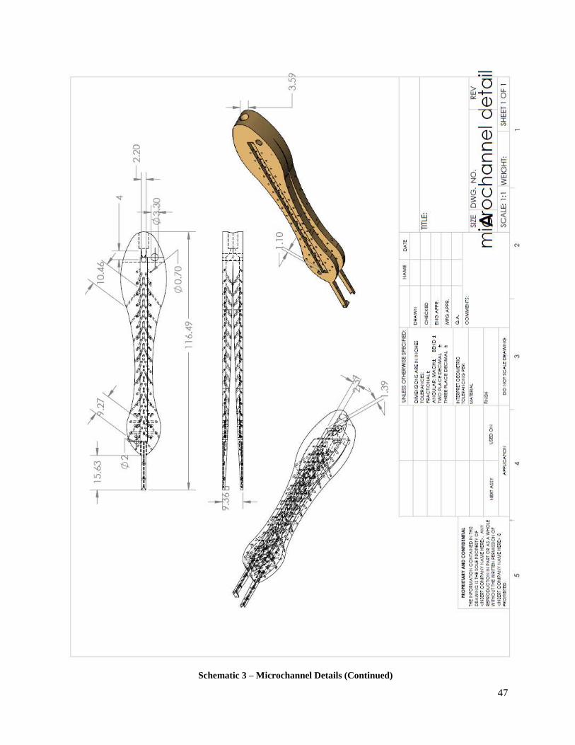
3.5 Microchannel Forceps Design
The next piece of hardware that will be discussed will be the forceps with
microchannels. In order to have a functioning tool, it was established that the size of the holes
would comply with the size of a typical sweat gland which ranges from a size of 500 to 700
micrometers. According to Salvo in the text “Wearable technologies for Sweat rate and
Conductivity Sensors”, sweat is excreted by the eccrine glands at a rate of 2-20nL/min or up to
8,000 mL/day, depending on the amount of activity. The tool was made under the assumption of
maximum excretion of sweat with holes at a diameter of 700 micrometers. Most of the solution
that will be used with the anti-microbial will be an aqueous NaCl which means a lot of the same
properties of the liquid compared to the composition of sweat will be maintained. Under a worst
case scenario of maximum suffusion from the tool, the estimated NaCl solution is theorized to
suffuse at a rate of 333 mL/Hour. This is why a 1000 mL bag was obtained to guarantee a
surgery of at least 3 hours without obtaining the attention of the surgeon. The tool was made in
mind of the currently existing materials that can easily be purchased in a wholesale manner such
as IV bags, spikes and pressure infusion bags.
The construction of the tools mentioned above was achieved with the 2013 version of
SolidWorks. After obtaining an authentic pair of Adson thumb forceps, the dimensions were
copied and modified to be able to insert a microchannel system within the tool. The process
began with extruding a solid boss base as pictured in Figures 9 and 10. Additional details and
dimensions of tool are included in Appendix 3.
Figure 9 – Trimetric View of Tool Main Body

25
Figure 10: Back View of Tool Body
The main problem encountered in this section was being able to clean the holding
material that was left behind in the holes of the tool. This material is left back in order to have a
sturdy structure while the 3D printing is constructing. Initially the tool was made as a single
piece which meant the holding material between each forcep would be nearly impossible to
remove. The solution that took care of the problem consisted of making a lid to the front and
back of the tool. When the lid is removed and the inner network of channels is displayed, the
holding material is successfully removed.

26
Chapter 4 –Test Data
After building the prototype, Design Team 1 implemented various testing methods to
ensure the tool had the desired functionality. The team wanted to test each part independently of
each other and then piece by piece integrate the separate modules into a whole system, testing
each integration along the way. This gave the team valuable data to validate if the instrument
was working properly or not. It also allowed the team to easily isolate any errors and
miscalculations that occurred during the design process.
The multiple testing methods included testing the pressure infusion bag with a hand
pump to record suffusion rate due to pressure, testing the motor with the power supply to ensure
the motor does not overdraw current, testing the Bluetooth connection at different levels with the
smart phone application, and testing the sensor feedback calibration on the microcontroller. The
following chapter gives an in-depth explanation of the different methods used to check the
accuracy of the proposed design and the conclusions drawn from the collected data.
4.1 Manual Testing
This testing involved the use of the hand pump and the pressure infusion bag. It was used
to measure the pressure range for optimal fluid suffusion independently from all other modules
of the system. The results of the testing are discussed in detail in the following subsections.
4.1.1 Suffusion Due to Pressure
In order for the tool to function properly, the group had to account for the movement of
the solution caused by gravity. This was compensated by setting the opening of the choke to a
distance of .32 inches. The tool was then tested by manually applying air to the pressure
infusion bag through an air pump. The initial starting pressure with the bag at the start up
settings was 50 mmHg and the tool was only suffusing a minor amount of fluid. The team then
began applying air to the bag at a rate of 2 pumps per minute and began taking a reading of the
pressure at this time. The members also observed the effect the change in pressure caused on the
suffusion of fluid on the surface of the tool.

27
Table 5 – Test Data Relating Suffusion of Fluid to Pressure
As shown in Table 5, the pressure increased approximately 4 mmHg per 2 pumps applied
to the pressure infusion bag. During the first 10 pumps the bottom of the tool became saturated
with fluid, however the top remained mostly dry. As the test continued, the tool became fully
suffused with antimicrobial at a sufficient rate. This is shown during pumps 12-18 which
produced a pressure roughly between 70 and 100 mmHg. This proved to be the ideal pressure
for the tool to function since the additional pumps performed resulted in an oversaturation of the
surgical tool leading to fluid dripping off the tool at an increased rate. The pressure bag also
appeared to be fully inflated and did not want to surpass the threshold pressure rated at
325mmHg. The information gathered from this test allowed the group to accurately implement
the feedback from the pressure sensor into the microcontroller and guaranteed the pressure limits
discovered above were met.
4.1.2 Pressure Drop Related to Time and Fluid Suffused
During this test the choke was slightly altered to .35 inches to determine if such a small
change would have an effect on the amount of fluid being suffused. The test was started with the
initial pressure reading of 100 mmHg and the timer was started. The time (in seconds) was
recorded each time the pressure reading dropped by 2 mmHg. At this time, the amount of fluid
being suffused through the tool was collected into a graduated cylinder and the difference was
recorded. The results are shown below in Table 6.

28
Table 6 – Test Data Relating Pressure Drop to Time and Amount of Fluid Suffused
A total collection of 2.3 mL was suffused through the tool after 6 minutes. This showed
that as the pressure decreased over time, the fluid continued to suffuse at a constant rate. This
indicates that as long as the pressure remains between 100 and 70 mmHg, the tool will be
properly suffused with the correct amount of antimicrobial.
4.2 Testing of Current
In order to power the motor, two options were considered. The first was a motor diver
which would be used to provide discrete voltages and the second consisted of powering the
circuit with one voltage supplied when the transistor is activated. To decide between these
choices, a simple test was conducted to determine the maximum current output produced based
on the voltage applied to motor. The results can be observed in the following graph.

29
Graph 1 – Results of Voltage Application to Motor
As the graph indicates, the maximum current recorded was .18 Amps. Since this was the
maximum voltage intended to run the motor, the low current allowed the option using the
transistor to be the lowest cost solution. If the current was greater than the maximum current
allowed by the 30N06Ltransistor, the motor diver with multiple input voltage options would
have been implemented. Subsequently by utilizing the transistor design, Team 1 reduced the
overall cost by $23.
4.3 Power Consumption
In order to identify the battery life, the system was turned on and the current was
measured at various points. The data collected is listed below.
System Powered on and Searching for Bluetooth Connection: 50 mA
After Bluetooth Connected to Mobile Device: ≈ 40-50 mA
Motor Running: 230 mA
As shown above, the system runs at approximately 50 mA when searching and connected to the
Bluetooth on the cellular application. This falls much lower than when the motor begins running
and draws 230 mA of current. The group concluded from this information that through
minimizing the amount of time the motor is running, the battery would be preserved longer.
0
0.02
0.04
0.06
0.08
0.1
0.12
0.14
0.16
0.18
0.2
0 1 2 3 4 5 6
Cu
rre
nt
(Am
ps)
Voltage (Volts)
Current Output of Motor
Current

30
Given that the battery has 565mAh of stored energy and using the data collected above,
the team was able to calculate the allotted run-time of the motor if the battery was to last six
hours. To achieve functionality for the duration of the surgery the motor would only be able to be
running 24% of the total time equating to 1 hour and 26 minutes. All calculations can be found in
Appendix 3.
4.4 Additional Testing
Although the team was able to conduct multiple tests related to the pressure, power
consumption, and suffusion rate, it would have been beneficial to continue with additional
testing in other areas. Such testing could include testing the sanitization of the tool through
applying bacteria to the surface and evaluating if the tool is capable to eliminating infection.
Other options could include a method to study and calculate the flow rate of solution entering
into the tool. This would allow an exact measurement of the amount of antimicrobial being
delivered to the forceps. Due to unforeseen circumstances resulting in limited time remaining,
Team 1 was unable to implement these desired experiments. In future iterations of the project, it
would be valuable to perform these tests to provide additional documentation to support the
proof of concept.

31
Chapter 5 – Surgical Tool: Final System Integration
Design Team 1 was tasked with the goal to create a self-suffusing surgical tool to be
utilized in unsanitary conditions. By using microchannels and pressure induced flowrates, the
team was successful in reaching the goals of the project. Furthermore by taking advantage of
readily available medical equipment and low cost electrical parts, the final prototype could be
produced at $139.80 per unit as shown in Table 8. This price falls well within the budget range
for the target consumer which is developing economies, and can be utilized to prevent surgical
site infections in patients. This means not only does the tool completely suffuse with the
antimicrobial, but it can be produced at a low cost such that it could be easily attained by
surgeons in third-world countries in need of such a product.
5.1 Summary
For the final prototype, the Adson Thumb Forceps are continuously suffused with
antimicrobials for the duration of up to six hours. This is accomplished through a series of
microchannels running through the tool supplying the drug to the surface. The drug delivery is
controlled by a pump and a pressure infusion bag and monitored by a pressure sensor. The
complete suffusion of the tool prevents any bacteria from growing on the surface. This in turn
ensures a clean tool and lowers the risk of infection greatly. This tool is to be utilized in
unsanitary environments, such as operating rooms in third-world countries.
Throughout the design process Design Team 1 had to overcome many obstacles. One
significant obstacle was setting up the microcontroller to receive feedback from the sensor and
placement of the sensor itself. To get an accurate reading of the pressure and the flow rate, the
sensor had to be placed as close to the mouth of the tool as possible which impairs mobility of
the tool. Another set-back the team faced was powering the pump with the microcontroller. Since
the microcontroller was low power, its output voltage of 3.3V was too low to power the pump
directly. Therefore the team had to figure out a way to turn the pump on and off according to the
values supplied by the sensor. These problems were described in detail along with Design Team
1’s solutions in the previous Chapters.
Overall Design Team 1 delivered a successful product to MSU College of Engineering
for implementation and further development. Team 1 is grateful to have been assigned such an

32
influential ECE 480 Design Project and proud to deliver a product that could save lives and
improve the quality of living for many.
5.2 Budget Management
Design Team 1 was allotted $500 at the beginning of the semester for the development
and creation of the final prototype. The team tried to utilize the budget as efficiently as possible
and exhausted all design ideas to decide which one was optimal for the system. This included
buying different parts and testing them against the system. The team also bought duplicate parts
to back up the more integral hardware in the system (e.g. the microcontroller, the pressure
sensor) in case any unforeseen accidents occurred. Upon the completion of the final prototype,
Design Team 1 has spent $407.12 total on the entire project, leaving $92.88 left in the budget
which can be seen in Table 7 below.
Table 7 – Total Money Spent for the Overall Project Components (Without Shipping)
If an individual would like to reproduce the final project created, the cost per tool would
be a total of $139.80. This unit cost is reasonable as the tool would be able to be reused for
many surgeries without the concern of contamination of the tool in the unsanitary environment.

33
Table 8 – Cost to Manufacture 1 Adson Thumb Forceps Self-Suffusing System
5.3 Time Management
The predicted schedule was slightly altered during the semester. The team had to adjust
the design after meeting with doctors at the College of Veterinary Medicine who proposed a new
cheaper design as outlined in Chapter 2. Despite the change in the proposed design, the team was
still able to complete the tool as scheduled.
5.4 Lessons Learned
When presented with set-backs and obstacles, it is important to learn from each instance
especially in engineering. Designing this tool, Team 1 was presented with many obstacles and
set-backs and gained valuable experience and knowledge of the design process. Some lessons
learned are as follows:
When scheduling, leave extra space for unexpected setbacks
Always budget and order back up parts for prototyping in case one part burns out
Pressure dissipation across a bendy tube is variable and pressure readings must be done
close to the output
Research all parts thoroughly and order in advance.

34
5.5 Future Improvements
The work that Design Team 1 has implemented is just the beginning. Different ECE 480
teams can continue to develop and improve the initial design. Moving forward, many
improvements could be made including but not limited to the following:
5.5.1 Continuously Powered Pump
Currently the microcontroller receives feedback from the sensor and then controls the pump
through discrete voltages. In future iterations of the project, the pump could be powered
continuously, changing the voltage levels depending on the feedback from the sensor. To
implement this, a PID controller will have to be applied to continuously get data and adjustments
from the sensor. Since the microcontroller currently doesn’t supply enough voltage to power the
pump directly, future teams will have to create a circuit that will step up the voltage while
assuring that the pins of the microcontroller aren’t burned out. This would be a good adjustment
to make to the current system because this would increase the accuracy of the pressure applied,
improving the distribution of the drug.
5.5.2 Bluetooth Controlled Sensor
The sensor is an integral part of the system. It calculates the pressure and sends feedback to
the microcontroller to adjust to the desired pressure. As stated in previous chapters, for the most
accurate reading the pressure sensor must be places as close to the output as possible. This
creates a mobility problem because with the sensor so close to the tool there has to be wires
running from the sensor back to the microcontroller. This limits the mobility of the surgeon and
the ability to operate on the patient. Having a sensor that connected via Bluetooth would allow
the surgeon to move freely without worrying about electrical wires running back a forth between
the sensor and the microcontroller. If implemented, this would have to be calibrated and tested
heavily. A fail safe would also have to be added in-case the sensor lost connection and stopped
sending feedback to the microcontroller.
5.5.3 Multi-Tool System
Lastly the system could be expanded to support more than one tool. This would include
the creation of different surgical instruments with microchannels running from the base to the

35
surface, having the different tools hook up to the same bag of antimicrobial without limiting the
mobility of the surgeon and incorporating all different tools on a minimal amount of
microcontrollers to control the power usage of the system. Incorporating more than one tool
presents many problems including keeping cost low and power usage low. By simultaneously
suffusing more than one tool, the microcontroller will have to receive feedback from multiple
sensors which would drive power and costs up. Future teams would have to alter the design and
devise a method to keep the product low cost while supplying the correct functionality.
5.5.4 Modifications Suggested by MSU College of Veterinary Medicine
Once the project was completed, it was demonstrated before Dr. Helene Pazak, who is
the Assistant Dean for Undergraduate Programs at MSU’s College of Veterinary Medicine. She
was extremely pleased with the overall Adson Thumb Forceps system created by the group. She
did however offer some suggestions to the group to implement with future iterations. The first is
to account for surgeons with longer hands by increasing the length of the surgical tool so it
would also fit comfortably in their hands. The second suggestion is to devise a method of
attaching the wires and tubing to the upper forearm of the surgeon. This would eliminate any
interference with the operating procedure and also would prevent the possibility of the surgeon
dropping the tool off the operating surface. Lastly, she emphasized the importance of a portable
system so it can easily be transported with the patient throughout a hospital.

36
Chapter 6 – Appendix 1
6.1 Technical and Non-Technical Roles and Responsibilities
In order to successfully complete the project within the allotted time, the group divided
work among team members. Below is a description of the technical and non-technical roles
carried out by each person.
Design team one members from left to right: Adam Stowe, Kasey Durkin, Parker Mojsiejenko,
Stephanie Le, and Jose Carmona

37
6.1.1 Adam Stowe
Mr. Adam Stowe’s non-technical role was the project
manager. Adam is responsible for creating the Gantt chart and
making sure the group is staying on schedule. He also is
responsible for staying in contact with the facilitator and
sponsor of the project and setting up the meetings. Adam
worked on the completion of the power circuit with Mr. Parker
Mojsiejenko. He researched individual parts that could be
implemented in the circuit to be able to get power to the
components along with the feedback loop with the sensor. The
circuit was first designed on paper utilizing voltage regulators to step the input 9 volt battery
down to 5 volts and 3.3 volts. He and Parker set up the 5 volt to go to the motor and then the
drain of the transistor at the end. The 3.3 was set up to go to the microcontroller and the gate of
the transistor. Adam designed tests for the surgical tool that were outlined to find any defect in
the tool or software to be able to fix the problem. He discovered flaws in the app and helped find
solutions. He also went around to other members and assisted with any problems that they were
having. This included soldering of the circuit on the board.
6.1.2 Jose Carmona
Mr. Jose Carmona’s technical role is the tool design
manager. Mr. Carmona is responsible for the construction and
modification of a working tool and its appendages. In order to be
successful in this matter, a basic knowledge of micro-fluidics
and its applications were learned. Additionally Jose developed
tests to observe the complete suffusion of the tool by taking note
of how different pressures affected the output of the
antimicrobial.
In addition of being the tool design manager, Mr.
Carmona was also appointed as the Presentation Manager for the
team. This consisted of taking other people’s section of the
presentation and consolidated and revised all presentations into one.

38
6.1.3 Kasey Durkin
Kasey Durkin assisted with various technical aspects of
the project throughout the semester. This began with the initial
research for the project design. This included learning more
about microchannels, microfluidics, and identifying the
constraints of the project. This continued with browsing the
internet for materials for the project which were then discussed
with the team and ordered.
She also assisted with the creation of design iterations
and evaluations of the positive features along with areas of
improvement for the future. Kasey participated in the testing of
the project with various pressure readings being taken in relation to the amount of fluid being
suffused through the tool. She tested the project in order to verify the completed implementation
of the self-suffusing surgical tool would meet the project constraints established at the beginning
of the semester.
Kasey also functioned as the team’s document editor and was responsible for the division
of reports and assignments along with reviewing the overall document prior to submission. She
assisted the group through creating outlines and ensuring each deadline was met with a well
written report.
6.1.4 Parker Mojsiejenko
Mr. Parker Mojsiejenko managed the programming and
purchasing for the team. Programming was done for the
microcontroller and Android application and included
interfacing a Bluetooth channel between the application and
controller. He also integrated the pressure sensor via an I2C
bus protocol. In addition to this, he also participated in circuit
design and offered assistance whenever a team decision needed
to be made.

39
6.1.5 Stephanie Le
Stephanie Le contributed to the final product in multiple ways. She presented ideas and
participated in the initial design conception. She also heavily researched and studied various
microcontrollers, eventually picking the microcontroller used in the final product. She assisted
Parker Mojsiejenko with the coding of the smart-phone
application and the microcontroller. Together they debugged
and calibrated the pressure sensor to feedback information to
the microcontroller and set up the user interface to control the
whole system. She also took part in all testing procedures and
data collection.
Along with those technical contributions, Stephanie was
also tasked as the website manager. This included designing
and creating the team webpage and all the information on it.
She also contributed to all written reports and presentations.

40
Chapter 7 - Appendix 2
7.1 References
A. O'Dwyer, "PID control: the early years," in Dublin Institute of Technology, Dublin,
2005."RFduino Datasheet," RFduino, Hermosa Beach, 2013.
N/A, "Tecnologic UK," [Online]. Available: http://www.t-uk.co.uk/articles/history-pid-
controllers. [Accessed 3 April 2015].
[Online]. Available: http://www.rfduino.com/wp-
content/uploads/2014/03/RFD22102.Prospective.Top_.png.
[Online]. Available: http://stm32f4-discovery.com/wp-content/uploads/pid-controller-
diagram.png.
[Online]. Available: http://www.rfduino.com/wp-
content/uploads/2014/03/RFD22121.Prospective.Top_.png.
“Surgical Site Infection (SSI) Event,” n. pag, Center for Disease Control. CDC, Jan. 2015. Web.
6 Feb. 2015.
Setty, Naveen, Manjunatha Nagaraja, Dinesh Nagappa, Chandrakumar Giriyaiah, Naveen
Gowda, and Revathi Naik. “A Study on Surgical Site Infections (SSI) and Associated
Factors in a Government Teritary Care Teaching Hospital in Mysory,
Karnataka.” International Journal of Medicine and Public Health. SCIBIOLMED, 26
May 2014. Web. 6 Feb. 2015.

41
Chapter 8 – Appendix 3
8.1 Project Block Diagram
8.2 Component Images
RFD22102 Microcontroller

42
Board Mount Pressure Sensor
Power Circuit Diagram

43
Power Circuit Image
IV Bag Encased in Pressure Infusion Bag

44
Adson Thumb Forceps- Design Iterations (from left to right, Make I, Make II, Make III,
and Make IV)

45
8.3 Adson Thumb Forceps Schematics
Schematic 1 – Prototype Lid

46
Schematic 2 – Microchannel Details
47
Schematic 3 – Microchannel Details (Continued)

48
8.4 Source Code
8.4.1 RFduino Code
// ECE480 RFduino code // Parker Mojsiejenko // // Operates a pump motor controlled via Bluetooth Low Energy. // A '1' starts the operation and a '0' stops it while a '3' requests information.
#include <Wire.h> #include <RFduinoBLE.h> boolean running = false; int seconds = 0; // time of operation // set pin numbers (5 and 6 are used for I2C) int pin2 = 2; // green LED int pin3 = 3; // red LED int pin4 = 4; // motor switch void RFduinoBLE_onReceive(char *data, int len) { // Serial.print("Data: "); Serial.println(data); // show recieved data int dataInt = atof(data); // turn data into int // handles the data recieved over BLE switch(dataInt) { case 0: running = false; Serial.println("Off Command Received"); break; case 1: running = true; Serial.println("On Command Received"); break; case 3: // sent when app starts RFduinoBLE.sendInt(seconds); Serial.println("Sent Seconds (loops) run"); break; default: break; } } // runs on BLE connection void RFduinoBLE_onConnect(){ Serial.println("Connected"); if(!running) { RFduinoBLE.sendInt(0); Serial.println("Sent Command 'Not Running' (0)"); } else { RFduinoBLE.sendInt(seconds); Serial.println("Sent Seconds (loops) run" + seconds); } digitalWrite(pin2,HIGH); // turn on GREEN LED digitalWrite(pin3,LOW); // turn off RED LED }

49
void RFduinoBLE_onDisconnect(){ digitalWrite(pin3,HIGH); // turn on RED LED digitalWrite(pin2,LOW); // turn off GREEN LED digitalWrite(pin4,LOW); // turn off motor Serial.println("Disconnected"); } void setup() { Wire.begin(); // turn on the I2C digitalWrite(pin3,HIGH); // turn on RED LED at startup pinMode(pin2,OUTPUT); // set pin2 as an output pinMode(pin3,OUTPUT); // set pin3 as an output pinMode(pin4,OUTPUT); // set pin4 as an output Serial.begin(9600); // start debugging serial communication Serial.println("Started"); RFduinoBLE.deviceName = "ECE480"; // name of your RFduino. Will appear when other BLE
enabled devices search for it RFduinoBLE.begin(); // start BLE stack RFduinoBLE.txPowerLevel = +2; // (2 dBs) power needed to ensure a quick connection } void loop() { while(running) { // run only if phone sends running command byte aa,bb,cc,dd,ee; // byte data from the sensor float pressure = 0; // initialize the pressure decimal Wire.requestFrom(0x28,4); // request 4 bytes of data from the sensor aa = Wire.read(); // first byte recieved stored here bb = Wire.read(); // second byte recieved stored here cc = Wire.read(); // third byte recieved stored here dd = Wire.read(); // forth byte recieved stored here /* // serial debugging code Serial.print("byte 1: "); Serial.println(aa,BIN); Serial.print("byte 2: "); Serial.println(bb,BIN); Serial.print("byte 3: "); Serial.println(cc,BIN); Serial.print("byte 4: "); Serial.println(dd,BIN); */ unsigned int c = aa*256+bb; //combines byte 1 and byte 2 //Serial.print("Combined byte: "); Serial.println(c,BIN); //Serial.print("Count #: "); Serial.println(c,DEC); // Conversion found from sensor technical notes pressure = (((c - 1623)*(160))/(14746-1639)); // display the pressure for debugging //Serial.print("Pressure: "); Serial.print(pressure); Serial.println(" mbar"); // run the pressure check code which is simpler than a PI controller and works just as
well if(pressure < 106 || pressure > 500) { // when pressure is under 106 mbar or over 500 mbar
which occours when sensor malfunction digitalWrite(pin4,HIGH); // turn 'on' transistor // Serial.println("TURN ON MOTOR"); } else if(pressure > 146) { digitalWrite(pin4,LOW); // turn 'off' transistor

50
// Serial.println("TURN OFF MOTOR"); } delay(1000); // 1 second delay between pressure readings seconds++; // increment the second counter //Serial.println(seconds); } }
8.4.2 Android Code
package com.mojo.pumpcontrol; import android.app.ActivityManager; import android.bluetooth.BluetoothAdapter; import android.bluetooth.BluetoothDevice; import android.bluetooth.BluetoothManager; import android.bluetooth.le.ScanCallback; import android.bluetooth.le.ScanFilter; import android.bluetooth.le.ScanResult; import android.bluetooth.le.ScanSettings; import android.content.BroadcastReceiver; import android.content.ComponentName; import android.content.Context; import android.content.Intent; import android.content.IntentFilter; import android.content.ServiceConnection; import android.os.Bundle; import android.os.CountDownTimer; import android.os.IBinder; import android.support.v7.app.ActionBarActivity; import android.util.Log; import android.view.Menu; import android.view.MenuItem; import android.view.View; import android.widget.Button; import android.widget.TextView; import java.util.ArrayList; import java.util.List;
public class MainActivity extends ActionBarActivity { // State machine final private static int STATE_BLUETOOTH_OFF = 1; final private static int STATE_DISCONNECTED = 2; final private static int STATE_CONNECTING = 3; final private static int STATE_CONNECTED = 4; private int state; private android.view.ViewGroup dataLayout; private boolean scanStarted; private CountDownTimer timer; private boolean scanning; private static RFduinoService rfduinoService; private TextView connectionStatusText; private TextView surgeryTimer; private Button startButton; private Button stopButton; private Button connectButton;

51
private Long seconds = (long) 0; private Long minutes = (long) 0; private String startOn = "1"; private String startOff = "0"; private List<ScanFilter> filterList = new ArrayList<ScanFilter>(); private boolean connected = false; private boolean running = false; private Intent rfduinoIntent; private final static String TAG = MainActivity.class.getSimpleName(); private BluetoothAdapter bluetoothAdapter; private BluetoothDevice bluetoothDevice; private final BroadcastReceiver bluetoothStateReceiver = new BroadcastReceiver() { @Override public void onReceive(Context context, Intent intent) { int state = intent.getIntExtra(BluetoothAdapter.EXTRA_STATE, 0); if (state == BluetoothAdapter.STATE_CONNECTED) { updateState(STATE_CONNECTED); } else if (state == BluetoothAdapter.STATE_CONNECTING) { updateState(STATE_CONNECTING); } else if (state == BluetoothAdapter.STATE_DISCONNECTED) { updateState(STATE_DISCONNECTED); } else if (state == BluetoothAdapter.STATE_OFF) { updateState(STATE_BLUETOOTH_OFF); } } }; private final ServiceConnection rfduinoServiceConnection = new ServiceConnection() { @Override public void onServiceConnected(ComponentName name, IBinder service) { // set the local service variable to the running service rfduinoService = ((RFduinoService.LocalBinder) service).getService(); // if the service initializes okay (references the BLE adapter) then connect to
the device if (rfduinoService.initialize()) { try { if (rfduinoService.connect(bluetoothDevice.getAddress())) { updateState(STATE_CONNECTING); Log.v(TAG, "Service Connected"); } } catch (NullPointerException e) { Log.e(TAG, "Service Connection Error"); } } } @Override public void onServiceDisconnected(ComponentName name) { // rfduinoService = null; updateState(STATE_DISCONNECTED); Log.v(TAG, "Service Disconnected"); } }; public void sendData(byte[] data) { if (!rfduinoService.send(data)) { scan();

52
} } private final BroadcastReceiver rfduinoReceiver = new BroadcastReceiver() { @Override public void onReceive(Context context, Intent intent) { final String action = intent.getAction(); if (RFduinoService.ACTION_CONNECTED.equals(action)) { connectButton.setEnabled(false); updateState(STATE_CONNECTED); } else if (RFduinoService.ACTION_DISCONNECTED.equals(action)) { connectButton.setEnabled(true); connected = false; updateState(STATE_DISCONNECTED); } else if (RFduinoService.ACTION_DATA_AVAILABLE.equals(action)) { addData(intent.getByteArrayExtra(RFduinoService.EXTRA_DATA)); } } }; public void scan() { scanStarted = true; updateUi(); ScanCallback scanCallback = new ScanCallback() { @Override public void onScanResult(int callbackType, ScanResult result) { //super.onScanResult(callbackType, result); bluetoothAdapter.getBluetoothLeScanner().stopScan(this); bluetoothDevice = result.getDevice(); if (!connected) { connectionStatusText.setText("Device found, connecting..."); startService(rfduinoIntent); bindService(rfduinoIntent, rfduinoServiceConnection, BIND_AUTO_CREATE); connected = true; } } }; /* if (Build.VERSION.SDK_INT < Build.VERSION_CODES.LOLLIPOP) { scanStarted = true; bluetoothAdapter.startLeScan( new UUID[]{RFduinoService.UUID_SERVICE}, MainActivity.this); connectionStatusText.setText("Connecting..."); if(!connected) { Intent rfduinoIntent = new Intent(MainActivity.this, RFduinoService.class); bindService(rfduinoIntent, rfduinoServiceConnection, BIND_AUTO_CREATE); connected = true; } } else if(Build.VERSION.SDK_INT >= Build.VERSION_CODES.LOLLIPOP) { */ ScanSettings scanSettings = new
ScanSettings.Builder().setScanMode(ScanSettings.CALLBACK_TYPE_ALL_MATCHES).build(); bluetoothAdapter.getBluetoothLeScanner().startScan(filterList, scanSettings,
scanCallback); // } }

53
@Override protected void onPause() { super.onPause(); //unbindService(rfduinoServiceConnection); } @Override protected void onResume() { super.onResume(); } @Override protected void onCreate(Bundle savedInstanceState) { super.onCreate(savedInstanceState); setContentView(R.layout.activity_main); rfduinoIntent = new Intent(MainActivity.this, RFduinoService.class); // initializes Bluetooth adapter final BluetoothManager bluetoothManager = (BluetoothManager) getSystemService(Context.BLUETOOTH_SERVICE); bluetoothAdapter = bluetoothManager.getAdapter(); // if(android.os.Build.VERSION.SDK_INT >= Build.VERSION_CODES.LOLLIPOP) { // clear and add a filter for the device scan filterList.clear(); filterList.add(new ScanFilter.Builder().setDeviceName("ECE480").build()); // } connectionStatusText = (TextView) findViewById(R.id.connectionStatus); // run the device scan scan(); // get UI components surgeryTimer = (TextView) findViewById(R.id.timer); startButton = (Button) findViewById(R.id.begin_button); stopButton = (Button) findViewById(R.id.stop_button); connectButton = (Button) findViewById(R.id.connect); connectButton.setEnabled(true); connectButton.setOnClickListener(new View.OnClickListener() { @Override public void onClick(View v) { scan(); } });
// start button on click listener startButton.setOnClickListener(new View.OnClickListener() { @Override public void onClick(View v) { if (startButton.getText().equals("Start")) { stopButton.setEnabled(true); startButton.setText("PAUSE"); startTimer(); if (!running) { sendData(startOn.getBytes());

54
running = true; } else { sendData(startOff.getBytes()); running = false; } } else if (startButton.getText().equals("PAUSE")) { startButton.setText("RESUME"); if (!running) { sendData(startOn.getBytes()); running = true; } else { sendData(startOff.getBytes()); running = false; } timer.cancel(); } else { if (!running) { sendData(startOn.getBytes()); running = true; } else { sendData(startOff.getBytes()); running = false; } startTimer(); //(int) pauseTime startButton.setText("PAUSE"); }
} }); // stop button on click listener stopButton.setOnClickListener(new View.OnClickListener() { @Override public void onClick(View v) { if (running) { sendData(startOff.getBytes()); running = false; } surgeryTimer.setText("0:00"); startButton.setText("START"); timer.cancel(); minutes = (long) 0; seconds = (long) 0; } }); if (isMyServiceRunning(RFduinoService.class)) { rfduinoService.send("3".getBytes()); } } private boolean isMyServiceRunning(Class<?> serviceClass) { ActivityManager manager = (ActivityManager)
getSystemService(Context.ACTIVITY_SERVICE); for (ActivityManager.RunningServiceInfo service :
manager.getRunningServices(Integer.MAX_VALUE)) { if (serviceClass.getName().equals(service.service.getClassName())) { return true; } } return false; }

55
public void setTime(int s) { Log.v(TAG, Integer.toString(s)); minutes = Long.valueOf(s / 60); seconds = Long.valueOf(s % 60); } public void startTimer() { // counts up timer = new CountDownTimer(1000 * 60 * 60 * 6, 1000) { // total time is 6 hours @Override public void onTick(long millisUntilFinished) { seconds++; seconds = seconds % 60; // increment the minutes if seconds has 0 remainder if (seconds == 0) { minutes++; } surgeryTimer.setText(String.format("%d:%02d", minutes, seconds)); } @Override public void onFinish() { surgeryTimer.setText("0:00");
} }.start(); }
@Override protected void onStart() { super.onStart(); // register the broadcast recievers registerReceiver(bluetoothStateReceiver, new
IntentFilter(BluetoothAdapter.ACTION_STATE_CHANGED)); registerReceiver(rfduinoReceiver, RFduinoService.getIntentFilter()); // figure out what this does updateState(bluetoothAdapter.isEnabled() ? STATE_DISCONNECTED :
STATE_BLUETOOTH_OFF); } private void updateState(int newState) { state = newState; updateUi(); }
@Override protected void onStop() { super.onStop(); // scan callback for stopScan() method // if (android.os.Build.VERSION.SDK_INT >= Build.VERSION_CODES.LOLLIPOP) { ScanCallback scanCallback = new ScanCallback() { @Override

56
public void onScanFailed(int errorCode) { super.onScanFailed(errorCode); } };
// stop the scanner to free the resources bluetoothAdapter.getBluetoothLeScanner().stopScan(scanCallback); // } else if(android.os.Build.VERSION.SDK_INT < Build.VERSION_CODES.LOLLIPOP) { // bluetoothAdapter.stopLeScan(this); // } }
protected void onDestroy() { super.onDestroy(); // unregister the broadcast receivers unregisterReceiver(bluetoothStateReceiver); unregisterReceiver(rfduinoReceiver); } private void updateUi() { //boolean on = state > STATE_BLUETOOTH_OFF; // update the connection text if (state == STATE_CONNECTING) { connectionStatusText.setText("Connecting..."); } else if (state == STATE_CONNECTED) { connected = true; connectionStatusText.setText("Connected"); } else { connectionStatusText.setText("Disconnected"); } } // change to a method that takes the data and process it like I need private void addData(byte[] data) { Log.v(TAG, "Data received: " + data); if (byteArrayToInt(data) == 0) { running = false; Log.v(TAG, "device is not running"); stopButton.setEnabled(false); } else { running = true; setTime(byteArrayToInt(data)); startTimer(); Log.v(TAG, "device is running"); startButton.setText("PAUSE"); stopButton.setEnabled(true); } } public static int byteArrayToInt(byte[] b) { return b[3] & 0xFF | (b[2] & 0xFF) << 8 | (b[1] & 0xFF) << 16 | (b[0] & 0xFF) << 24; } @Override public boolean onCreateOptionsMenu(Menu menu) { // Inflate the menu; this adds items to the action bar if it is present.

57
getMenuInflater().inflate(R.menu.menu_main, menu); return true; } @Override public boolean onOptionsItemSelected(MenuItem item) { // Handle action bar item clicks here. The action bar will // automatically handle clicks on the Home/Up button, so long // as you specify a parent activity in AndroidManifest.xml. int id = item.getItemId(); //noinspection SimplifiableIfStatement if (id == R.id.action_settings) { return true; } return super.onOptionsItemSelected(item); } }
8.4.3 RFduinoService
package com.mojo.pumpcontrol; import android.Manifest; import android.app.Service; import android.bluetooth.BluetoothAdapter; import android.bluetooth.BluetoothDevice; import android.bluetooth.BluetoothGatt; import android.bluetooth.BluetoothGattCallback; import android.bluetooth.BluetoothGattCharacteristic; import android.bluetooth.BluetoothGattDescriptor; import android.bluetooth.BluetoothGattService; import android.bluetooth.BluetoothManager; import android.bluetooth.BluetoothProfile; import android.content.Context; import android.content.Intent; import android.content.IntentFilter; import android.os.Binder; import android.os.IBinder; import android.util.Log; import java.util.UUID; /* * Adapted from: *
http://developer.android.com/samples/BluetoothLeGatt/src/com.example.android.bluetoothlegat
t/BluetoothLeService.html */ public class RFduinoService extends Service { private final static String TAG = RFduinoService.class.getSimpleName(); private BluetoothManager mBluetoothManager; private BluetoothAdapter mBluetoothAdapter; private String mBluetoothDeviceAddress; private BluetoothGatt mBluetoothGatt; private BluetoothGattService mBluetoothGattService; public final static String ACTION_CONNECTED = "com.rfduino.ACTION_CONNECTED"; public final static String ACTION_DISCONNECTED =

58
"com.rfduino.ACTION_DISCONNECTED"; public final static String ACTION_CONNECTING = "com.rfduino.ACTION_CONNECTING"; public final static String ACTION_DATA_AVAILABLE = "com.rfduino.ACTION_DATA_AVAILABLE"; public final static String EXTRA_DATA = "com.rfduino.EXTRA_DATA"; public final static UUID UUID_SERVICE = BluetoothHelper.sixteenBitUuid(0x2220); public final static UUID UUID_RECEIVE = BluetoothHelper.sixteenBitUuid(0x2221); public final static UUID UUID_SEND = BluetoothHelper.sixteenBitUuid(0x2222); public final static UUID UUID_DISCONNECT = BluetoothHelper.sixteenBitUuid(0x2223); public final static UUID UUID_CLIENT_CONFIGURATION =
BluetoothHelper.sixteenBitUuid(0x2902); // Implements callback methods for GATT events that the app cares about. For example, // connection change and services discovered. private final BluetoothGattCallback mGattCallback = new BluetoothGattCallback() { @Override public void onConnectionStateChange(BluetoothGatt gatt, int status, int newState) { if (newState == BluetoothProfile.STATE_CONNECTED) { Log.i(TAG, "Connected to RFduino."); Log.i(TAG, "Attempting to start service discovery:" + mBluetoothGatt.discoverServices()); } else if (newState == BluetoothProfile.STATE_DISCONNECTED) { Log.i(TAG, "Disconnected from RFduino."); broadcastUpdate(ACTION_DISCONNECTED); } else if (newState == BluetoothProfile.STATE_CONNECTING) { Log.i(TAG, "Connecting to RFduino."); broadcastUpdate(ACTION_CONNECTING); } } @Override public void onServicesDiscovered(BluetoothGatt gatt, int status) { if (status == BluetoothGatt.GATT_SUCCESS) { mBluetoothGattService = gatt.getService(UUID_SERVICE); if (mBluetoothGattService == null) { Log.e(TAG, "RFduino GATT service not found!"); return; } BluetoothGattCharacteristic receiveCharacteristic = mBluetoothGattService.getCharacteristic(UUID_RECEIVE); if (receiveCharacteristic != null) { BluetoothGattDescriptor receiveConfigDescriptor = receiveCharacteristic.getDescriptor(UUID_CLIENT_CONFIGURATION); if (receiveConfigDescriptor != null) { gatt.setCharacteristicNotification(receiveCharacteristic, true); receiveConfigDescriptor.setValue( BluetoothGattDescriptor.ENABLE_NOTIFICATION_VALUE); gatt.writeDescriptor(receiveConfigDescriptor); } else { Log.e(TAG, "RFduino receive config descriptor not found!"); } } else { Log.e(TAG, "RFduino receive characteristic not found!"); } broadcastUpdate(ACTION_CONNECTED); } else { Log.w(TAG, "onServicesDiscovered received: " + status);

59
} } @Override public void onCharacteristicRead(BluetoothGatt gatt, BluetoothGattCharacteristic characteristic, int status) { if (status == BluetoothGatt.GATT_SUCCESS) { broadcastUpdate(ACTION_DATA_AVAILABLE, characteristic); } } @Override public void onCharacteristicChanged(BluetoothGatt gatt, BluetoothGattCharacteristic characteristic) { broadcastUpdate(ACTION_DATA_AVAILABLE, characteristic); } }; // connection state broadcast private void broadcastUpdate(final String action) { final Intent intent = new Intent(action); sendBroadcast(intent, Manifest.permission.BLUETOOTH); } // data transfer broadcast private void broadcastUpdate(final String action, final BluetoothGattCharacteristic characteristic) { if (UUID_RECEIVE.equals(characteristic.getUuid())) { final Intent intent = new Intent(action); intent.putExtra(EXTRA_DATA, characteristic.getValue()); sendBroadcast(intent, Manifest.permission.BLUETOOTH); } } // returns the service public class LocalBinder extends Binder { RFduinoService getService() { return RFduinoService.this; } } @Override public IBinder onBind(Intent intent) { return mBinder; } @Override public boolean onUnbind(Intent intent) { // After using a given device, you should make sure that BluetoothGatt.close() is
called // such that resources are cleaned up properly. In this particular example, close()
is // invoked when the UI is disconnected from the Service. // close(); return super.onUnbind(intent); } private final IBinder mBinder = new LocalBinder(); /** * Initializes a reference to the local Bluetooth adapter. *

60
* @return Return true if the initialization is successful. */ public boolean initialize() { // For API level 18 and above, get a reference to BluetoothAdapter through // BluetoothManager. if (mBluetoothManager == null) { mBluetoothManager = (BluetoothManager)
getSystemService(Context.BLUETOOTH_SERVICE); if (mBluetoothManager == null) { Log.e(TAG, "Unable to initialize BluetoothManager."); return false; } } mBluetoothAdapter = mBluetoothManager.getAdapter(); if (mBluetoothAdapter == null) { Log.e(TAG, "Unable to obtain a BluetoothAdapter."); return false; } return true; } /** * Connects to the GATT server hosted on the Bluetooth LE device. * * @param address The device address of the destination device. * @return Return true if the connection is initiated successfully. The connection
result * is reported asynchronously through the * {@code BluetoothGattCallback#onConnectionStateChange(android.bluetooth.BluetoothGatt,
int, int)} * callback. */ public boolean connect(final String address) { if (mBluetoothAdapter == null || address == null) { Log.w(TAG, "BluetoothAdapter not initialized or unspecified address."); return false; } // Previously connected device. Try to reconnect. if (mBluetoothDeviceAddress != null && address.equals(mBluetoothDeviceAddress) && mBluetoothGatt != null) { Log.d(TAG, "Trying to use an existing mBluetoothGatt for connection."); return mBluetoothGatt.connect(); } final BluetoothDevice device = mBluetoothAdapter.getRemoteDevice(address); // We want to directly connect to the device, so we are setting the autoConnect // parameter to false. mBluetoothGatt = device.connectGatt(this, false, mGattCallback); Log.d(TAG, "Trying to create a new connection."); mBluetoothDeviceAddress = address; return true; } /** * Disconnects an existing connection or cancel a pending connection. The disconnection
result * is reported asynchronously through the * {@code BluetoothGattCallback#onConnectionStateChange(android.bluetooth.BluetoothGatt,
int, int)} * callback. */
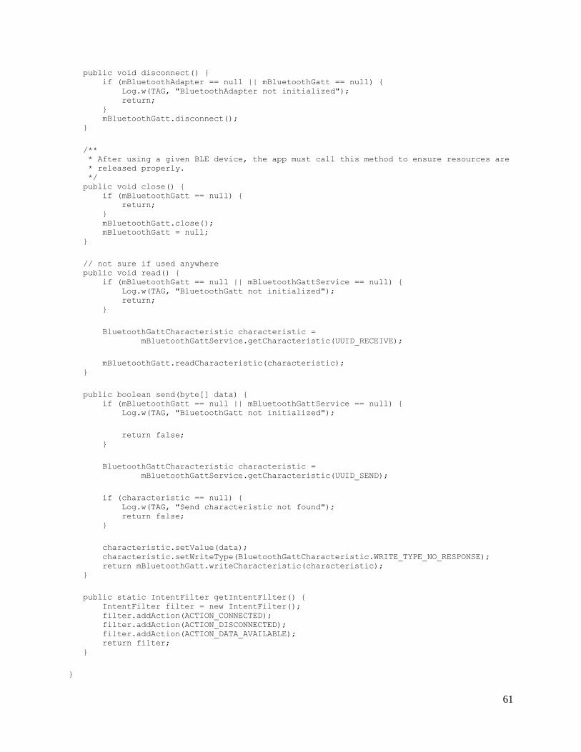
61
public void disconnect() { if (mBluetoothAdapter == null || mBluetoothGatt == null) { Log.w(TAG, "BluetoothAdapter not initialized"); return; } mBluetoothGatt.disconnect(); } /** * After using a given BLE device, the app must call this method to ensure resources are * released properly. */ public void close() { if (mBluetoothGatt == null) { return; } mBluetoothGatt.close(); mBluetoothGatt = null; } // not sure if used anywhere public void read() { if (mBluetoothGatt == null || mBluetoothGattService == null) { Log.w(TAG, "BluetoothGatt not initialized"); return; } BluetoothGattCharacteristic characteristic = mBluetoothGattService.getCharacteristic(UUID_RECEIVE); mBluetoothGatt.readCharacteristic(characteristic); } public boolean send(byte[] data) { if (mBluetoothGatt == null || mBluetoothGattService == null) { Log.w(TAG, "BluetoothGatt not initialized"); return false; } BluetoothGattCharacteristic characteristic = mBluetoothGattService.getCharacteristic(UUID_SEND); if (characteristic == null) { Log.w(TAG, "Send characteristic not found"); return false; } characteristic.setValue(data); characteristic.setWriteType(BluetoothGattCharacteristic.WRITE_TYPE_NO_RESPONSE); return mBluetoothGatt.writeCharacteristic(characteristic); } public static IntentFilter getIntentFilter() { IntentFilter filter = new IntentFilter(); filter.addAction(ACTION_CONNECTED); filter.addAction(ACTION_DISCONNECTED); filter.addAction(ACTION_DATA_AVAILABLE); return filter; } }

62
8.5 Power Consumption Calculations
Given the stored energy of the battery to be 565mAh, power consumption of the circuit
when the motor is off to be 50mA, power consumption when the motor is on to be 230mA and
the desired runtime of 6 hours, the runtime of the motor was calculated as follows
565𝑚𝐴ℎ
6 ℎ𝑜𝑢𝑟𝑠= 94.166𝑚𝐴
94.166 = 50𝑥 + 230𝑦
𝑦 = 1 − 𝑥
∴ 94.166 = 50𝑥 + 230(1 − 𝑥)
135.834 = 180𝑥
𝑥 = .76 𝑎𝑛𝑑 𝑦 = .24
With x representing the percentage of time the motor is off, the motor can be running a
maximum of 24% of the allotted runtime. This equals 1 hour and 26 minutes of the total 6 hours.
8.6 Links to Data Sheets
30N06L:
http://dlnmh9ip6v2uc.cloudfront.net/datasheets/Components/General/FQP30N06L.pdf
Board Mount Pressure Sensor SMT:
http://sensing.honeywell.com/index.php?ci_id=151133
LEDs: https://www.sparkfun.com/datasheets/Components/YSL-R596CR3G4B5C-
C10.pdf
LM2940: http://www.ti.com/lit/ds/symlink/lm2940c.pdf
LM3940: http://www.ti.com/lit/ds/symlink/lm3940.pdf
RFD22102: http://www.rfduino.com/wp-content/uploads/2014/03/rfduino.datasheet.pdf
RFD22301: http://www.rfduino.com/wp-
content/uploads/2014/03/RFD22301.Data_.Sheet_.11.24.13_11.38PM.pdf