ADSC/University of Arkansas/AHTD · array of laboratory test data and field load test data from...
5
Transcript of ADSC/University of Arkansas/AHTD · array of laboratory test data and field load test data from...


This is the second in a series of articles that chronicles thejoint ADSC-University of Arkansas-Arkansas AHTD DrilledShaft Research Project. ADSC Members are supplying signifi-cant “Contributions-in-Kind,” and the association’s IndustryAdvancement Fund is providing financial support. The first ar-ticle appeared in the January 2014 edition of FoundationDrilling magazine. See page 23 of that issue. We will continuethis reporting as the multi-phased project moves along. (Editor)
The Arkansas Highway and Transportation Department(AHTD) has adopted the classic, and often stated, “Mis-souri-like approach” when it comes to using drilled shaftfoundations for state transportation projects. Despite a vastarray of laboratory test data and field load test data fromdrilled shaft projects around the world, AHTD officialshave said, “Show me.” Historically, drilled shaft foundationshave been used for state transportation projects inArkansas onlywhen hard rock is present. AHDT policy hasmaintained that information regarding soil strength param-eters in the state has not been sufficiently reliable to permitsafe and economical installation of structures supported bydrilled shafts. This lack of trust in drilled shafts has beenparticularly strong in the northeastern portion of the statewhere the New Madrid Fault presents significant seismicrisks.
Dr. Rick Coffman, of the University of Arkansas, hastaken on the challenge to prove that drilled shaft founda-tions can be designed and constructed in an efficient andeconomical manner. (Foundation Drilling, January, 2014).With the help of ADSC Contractor Members, Aldridge
Construction, Inc., Frisco, Texas, and McKinney Drilling,Memphis, Tennessee, drilled shafts are being installed atthree sites across the state. Those sites were selected as rep-resenting the predominant subsurface conditions inArkansas.
The first portion of the project involved comparativesubsurface investigations at the three sites. Coffman andUniversity of Arkansas students explored each site usingstandard penetration testing with a California split spoon
sampler, Shelby tube sampling, and rock coring. TheAHDT explored the sites using only a standard split spoonsampler. The Missouri Department of Transportation(MODOT) participated by performing cone penetrationtesting, but no rock was cored. The in-depth subsurfaceexploration program was used to provide sufficient data toevaluate soil and rock strength for design.
Aldridge Construction is a contractor with extensiveexperience installing electrical and communicationstructure foundations. Aldridge drilled three shafts at thefirst test site in Siloam Springs in the northwestern partof the state. This location had been chosen because of
FOUNDATION DRILLING July 2014 Page 2
(Continued on page 30)
Feature
Dr. Rick Coffman, of the University of Arkansas, hastaken on the challenge to prove that drilled shaftfoundations can be designed and constructed in anefficient and economical manner. (FoundationDrilling, January, 2014).
ADSC/University of Arkansas/AHTDDrilled Shaft Research Project, Phase I
By Peggy Hagerty Duffy, P.E., ADSC Technical Advisor
Two cranes and two drill rigs being utilized by McKinney Drilling at the Turrell, Arkansas, site prior to adding the bottom section of therebar cage to the 1.8 meter diameter drilled shaft.
Page 3 FOUNDATION DRILLING July 2014
the presence of high strength limestone throughout the area.Two of the shafts were 1.2 meters in diameter, and the third was1.8 meters in diameter.
The quality of the limestone became evident very quickly whenrock coring times continued well past the duration originally es-timated. Aldridge was forced to shorten the length of two of theshafts in order to fit the project into the time they had allotted forthis generous donation of in-kind labor and equipment use. Thefinal lengths of the rock sockets were 3.0 meters (1.2-meter diam-eter), 1.5 meters (1.8-meter diameter), and 2.1 meters (1.2-meterdiameter).
Each excavation was equipped with four strain gauges, fourcrosshole sonic logging (CSL) tubes, five telltale pipes, and a bi-directional load cell (O-cell®) provided by ADSC Associate Mem-ber Loadtest, Inc., of Gainesville, Florida. Instrumentation wasinstalled by Aldridge and by members of the research team.
Construction methods were uniform for all three shafts, withone notable exception. While concrete was placed immediatelyafter completion of drilling for the two 1.2-meter diameter shafts,a delay of two and a half days occurred before concrete was placedfor the 1.8-meter diameter shaft.
GEI Consultants, of Libertyville, Illinois, led by Past ADSCBoard Member Bernie Hertlein, conducted CSL testing after con-crete was placed. Test results indicated that concrete was contin-uous and that no significant voids were present within the portionsof the shafts studied.
Full-scale load testing was executed using the O-cells installedduring shaft construction. Movement at the tops and bottoms ofthe O-cells were calculated, and mobilized load transfer charac-teristics for the shafts were obtained from strain gauge data. Thepredetermined axial capacities were met or were exceeded for allthree shafts.
Differences in movement were recorded between the shafts,with the 1.8-meter diameter shaft experiencing significantly moreupward movement than the other two shafts. Possible entrapmentof debris below the O-cell plate in one of the 1.2-meter diametershafts and retrofits to the instrumentation in the shortened shaftswere two possible reasons for the variations in the data. However,the delay in concrete placement was considered to be a likely causeof greater movement perhaps due to the possibility of changes to
(Continued on page 33)
RESEARCH Contd.
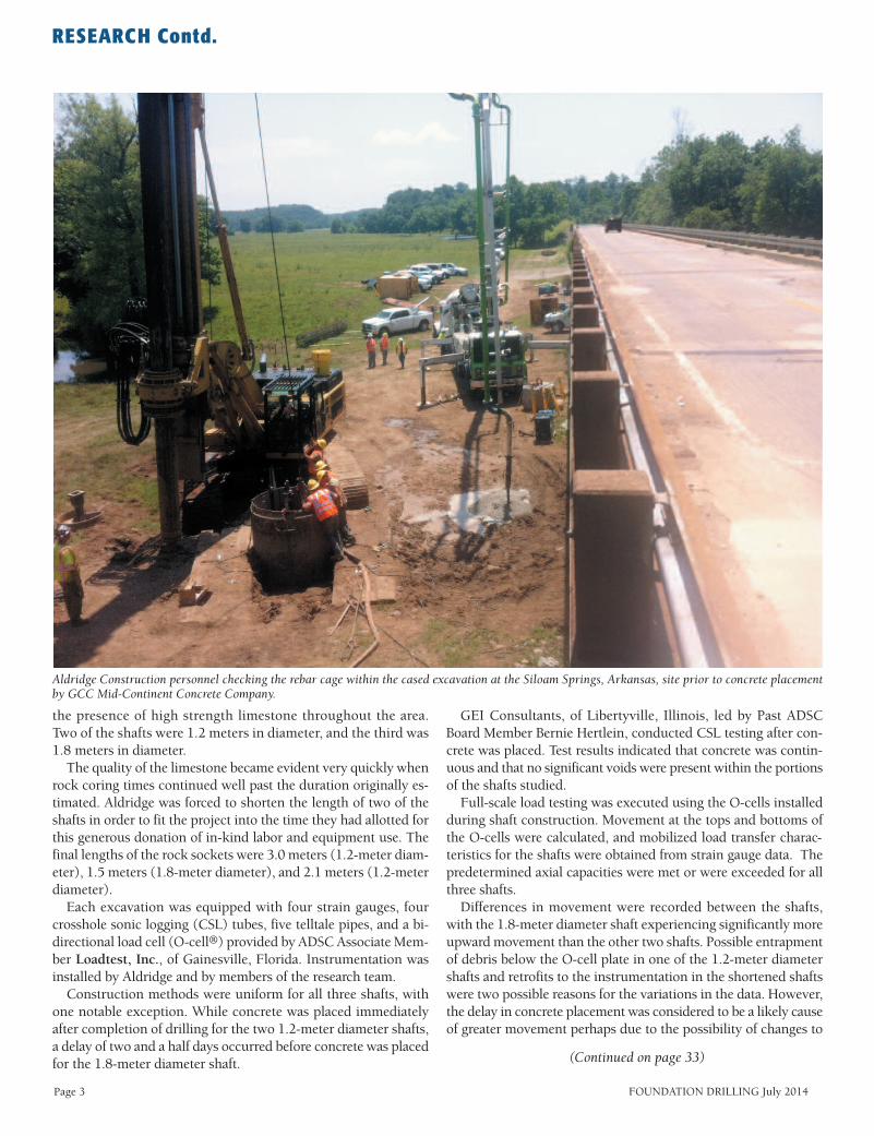
Aldridge Construction personnel checking the rebar cage within the cased excavation at the Siloam Springs, Arkansas, site prior to concrete placementby GCC Mid-Continent Concrete Company.

the rock socket sides while they were exposed to the elements dur-ing the delay. The data were also affected by the shortening ofplanned shaft diameters caused by extended drilling duration. Thesockets were not sufficiently deep in two of the shafts to facilitateapplication of pressure equal to 2.5 times the unconfined com-pressive strength of the limestone.
Based on load test results in the hard limestone, Coffman andhis team concluded that unit base resistance should be increasedto ten percent of the compressive strength of rock for strong lime-stone. This value was 10 MPa at the Siloam Springs site.
The second site was located at Turrell, in the northeastern por-tion of Arkansas and within the New Madrid seismic zone. Stratig-raphy at this site consisted of almost 10 meters of clay and siltunderlain by sand.
Contractor McKinney Drilling Co. was required to deal with ac-cess issues before drilling even began. The site was located in aninterstate median with drainage channels on both sides and soft,poorly drained surface conditions. Fill was placed to bridge thedrainage channel and to permit construction materials to be un-loaded. The poor drainage conditions came into play as tempera-tures dropped and ice formed at the ground surface complicating
movement around the site and creating safety hazards.Two 1.2-meter diameter drilled shafts and one 1.8-meter drilled
shaft were constructed at the project location. Instrumentation in-
cluded strain gauges, O-cells provided by Loadtest, CSL tubes, andfive telltale pipes. Some variations in progress were encounteredduring drilling the three shafts, most were functions of badweather and equipment issues.
A sheared pin on the drill rig and movement problems causedby icing on the drill mats caused several delays during completionof the first shaft. Concrete was placed 15 days after drilling beganfor that shaft.
Water was used in the second shaft to allow sonic borehole test-ing, and the completed excavation was left open overnight after
FOUNDATION DRILLING July 2014 Page 4
(Continued on page 34)
RESEARCH Contd.
Based on load test results in the hard limestone, Coffman and his team concluded that unit base resistance should beincreased to ten percent of the compressive strength of rockfor strong limestone. This value was 10 MPa at the SiloamSprings site.
McKinney Drilling personnel overseeing concrete placement within the 1.8-meter drilled shaft foundation excavation at the Turrell, Arkansas, site.

Page 5 FOUNDATION DRILLING July 2014
testing was complete and the reinforcing steel cage had been low-ered into place. The following morning, McKinney personnel ob-served a collapse of silt at the bottom of the shaft below the bottomof the temporary casing. Silt had slumped into the shaft, partiallycovering the steel cage. It was necessary to remove the cage andre-drill the shaft before concrete placement took place. As a resultof voids created by the collapse, approximately 9 cubic meters ofadditional concrete were needed to complete this shaft. The theo-retical volume of silt collapsing into the excavation was 19.9 cubicmeters.
CSL testing was again performed by Bernie Hertlein. Test resultsindicated that the concrete was free of significant discontinuities,although a small volume of possible sediment was detected wherethe collapse had taken place. Complications in the testing sug-gested that the collapse may have affected the instrumentation,however, Hertlein concluded from the overall data that the shaftconcrete was suitable to perform full-scale load testing.
Full-scale load testing demonstrated that the collapse in theshaft excavation had a significant effect on side shear and axial ca-pacity of that shaft, nonetheless design capacity of the shaft wasachieved. Test results indicated that side shear values were reducedfor the completed shaft where the collapse had occurred, and agreater percentage of the load was transferred to end bearing. Inaddition, movement in the shaft was three times that of the other
shaft where no collapse occurred.Unit side resistance increased with depth in the clay layers in
both shafts. The maximum value of side resistance within the claywas greater for the shaft where the collapse had occurred. This in-crease was assumed to be associated with the greater displacementassociated with filling the void left by the collapse. Conversely, theunit side resistance was significantly higher in the shaft in the sandlayers where no collapse occurred.
The research team concluded that collapses during shaft exca-vations may not necessarily lead to insufficient capacity. Re-drilling
the excavation and extending the shaft just past the original exca-vation bottom appeared to be suitable remedial measures toachieve adequate side shear and end bearing in the completedshaft.
The team also concluded that reductions in unit weights werenecessary when modeling collapsed shaft load-displacement be-havior. The percentage reduction varied from 10 percent to 30 per-cent for the modeling programs used in the research program.Appropriate reductions will depend on the program employed.
The University of Arkansas/AHTD research program is contin-uing with drilling activities at the third site in Monticello, in thesoutheastern part of the state. This is scheduled to begin in thesummer of 2014. Data obtained thus far have provided valuableinsights into factors affecting design, construction and perform-ance of drilled shafts in the specific conditions present within the
state of Arkansas. Many of these conclusions can be applied tosimilar geologic conditions elsewhere in the world, and many ofthe “takeaways” relative to drilling and concrete placement pro-cedures can be applied in most project settings. More detailed find-ings and conclusions will be in given a series of publications byDr. Coffman and his research team.
The AHTD has demonstrated their commitment to understand-ing drilled shafts for possible future use in transportation projectsby approving an additional phase of this research project involvingperformance of drilled shafts in seismic conditions. Field-testingwill take place at the Turrell site.
It is anticipated that the final storehouse of improved informa-tion will be utilized in specifying drilled shaft foundations for someportion of the nearly $10 billion in transportation projects slatedfor the next ten years.
RESEARCH Contd.
The AHTD has demonstrated their commitment to understanding drilled shafts for possible future use in transportation projects by approving an additional phase ofthis research project involving performance of drilled shaftsin seismic conditions.
It is anticipated that the final storehouse of improved information will be utilized in specifying drilled shaft foundations for some portion of the nearly $10 billion intransportation projects slated for the next ten years.
The 1.2-meter diameter by 8.8-meter long rebar cage being lifted into placeby Aldridge Construction after affixing the LoadTest O-Cell to the bottomof the rebar cage at the Siloam Springs, Arkansas, site.


![[MS-ADSC-Diff]: Active Directory Schema Classes... · 2 / 134 [MS-ADSC-Diff] - v20160714 Active Directory Schema Classes Copyright © 2016 Microsoft Corporation Release: July 14,](https://static.fdocuments.in/doc/165x107/6034874437704a05821ff686/ms-adsc-diff-active-directory-schema-classes-2-134-ms-adsc-diff-v20160714.jpg)


![[MS-ADSC]: Active Directory Schema Classes€¦ · 2 / 134 [MS-ADSC] - v20150630 Active Directory Schema Classes Copyright © 2015 Microsoft Corporation Release: June 30, 2015 Revision](https://static.fdocuments.in/doc/165x107/5f079c437e708231d41dd832/ms-adsc-active-directory-schema-classes-2-134-ms-adsc-v20150630-active.jpg)