ADS-SE1/2C-18 ADS-SE1/2 Controller 1. Follow as below when adjusting wiring length. Cut off the...
6
C-16 ADS-SE1/2 Features ● Long sensing distance: 0 to 10m ● High ambient intensity of illumination: Max. 100,000lx of sunlight ● Easy to connect sensor head to controller ● Easy sensitivity setting (automatic sensitivity setting by one push method) ● Self-diagnosis function ● Compact Size (W77×L44×H24mm) : minimized max. 20% than existing product (based on depth) Model ADS-SE1 (1-channel) ADS-SE2 (2-channel) Sensing type Through-beam type Sensing distance 0 to 10m Power supply 12-24VAC ±10% 50/60Hz / 12-24VDC ±10% (Ripple P-P: Max. 10% ) Power consumption/Current AC: Max. 2VA, DC: Max. 50mA Control output ※1 Contact capacity: 50VDC 0.3A (resistive load) Contact composition: 1c Relay life cycle: Mechanical- Min. 5,000,000 operations, Electrical- Min. 100,000 operations Response time Approx. 50ms (from light OFF) Output holding time Approx. 500ms (from light ON) Available sensor set 1 channel 2 channels Indicator OUT1 indicator: red, OUT2 indicator: green (Refer to C-20 for the display status in operation) Light source Infrared LED (850nm modulated) Vibration 1.5mm amplitude at frequency of 10 to 55Hz (for 1min.) in each X, Y, Z direction for 2 hours Shock 500m/s 2 (approx. 50G) in each X, Y, Z direction for 3 times Environ- ment Ambient illumination Sunlight: Max. 100,000lx (Receiver illumination) Ambient temperature -20 to 55℃, storage: -25 to 60℃ Ambient humidity 35 to 85% RH, storage: 35 to 85% RH Protection structure IP30 (IEC standard) Sensor cable length 5m Sensor cable Ø2.4mm, 1-wire, length: 5m (AWG26, core diameter: 0.16mm, number of cores: 7, insulator out diameter: Ø1.32mm) Material Case: ABS, Lens: PMMA Accessory Sensor 1set (ADS-SHP), Fixing bolt (M4×20) for controller: 2EA Approval Weight ※2 Approx. 450g (approx. 300g) Please read “Caution for your safety” in operation manual before using. Door Side Sensor Specifications ※1: Do not use Load which is beyond the rated capacity of contact point of Relay. It can cause bad insulation, contact fusion, bad contact, relay breakdown, and fire etc. ※2: The weight includes packaging. The weight in parentheses is for unit only. ※Please purchase 1 set of sensor separately when mounting 2 sets of sensor. ※The mounting bracket of sensor (ADS-SB12, ADS-SB10) is sold separately. ※ It is enable to purchase a controller (ADS-SEC1/2) separately. ※The temperature or humidity mentioned in Environment indicates a non freezing or condensation environment.
Transcript of ADS-SE1/2C-18 ADS-SE1/2 Controller 1. Follow as below when adjusting wiring length. Cut off the...

C-16
ADS-SE1/2
Features● Long sensing distance: 0 to 10m ● High ambient intensity of illumination: Max. 100,000lx of sunlight ● Easy to connect sensor head to controller ● Easy sensitivity setting (automatic sensitivity setting by one push method) ● Self-diagnosis function ● Compact Size (W77×L44×H24mm) : minimized max. 20% than existing product (based on depth)
Model ADS-SE1 (1-channel) ADS-SE2 (2-channel)
Sensing type Through-beam type
Sensing distance 0 to 10m
Power supply 12-24VAC ±10% 50/60Hz / 12-24VDC ±10% (Ripple P-P: Max. 10% )
Power consumption/Current AC: Max. 2VA, DC: Max. 50mA
Control output ※1 Contact capacity: 50VDC 0.3A (resistive load) Contact composition: 1c Relay life cycle: Mechanical- Min. 5,000,000 operations, Electrical- Min. 100,000 operations
Response time Approx. 50ms (from light OFF)
Output holding time Approx. 500ms (from light ON)
Available sensor set 1 channel 2 channels
Indicator OUT1 indicator: red, OUT2 indicator: green (Refer to C-20 for the display status in operation)
Light source Infrared LED (850nm modulated)
Vibration 1.5mm amplitude at frequency of 10 to 55Hz (for 1min.) in each X, Y, Z direction for 2 hours
Shock 500m/s2 (approx. 50G) in each X, Y, Z direction for 3 times
Environ-ment
Ambient illumination Sunlight: Max. 100,000lx (Receiver illumination)
Ambient temperature -20 to 55℃, storage: -25 to 60℃
Ambient humidity 35 to 85% RH, storage: 35 to 85% RH
Protection structure IP30 (IEC standard)
Sensor cable length 5m
Sensor cable Ø2.4mm, 1-wire, length: 5m (AWG26, core diameter: 0.16mm, number of cores: 7, insulator out diameter: Ø1.32mm)
Material Case: ABS, Lens: PMMA
Accessory Sensor 1set (ADS-SHP), Fixing bolt (M4×20) for controller: 2EA
Approval
Weight※2 Approx. 450g (approx. 300g)
Please read “Caution for your safety” in operation manual before using.
Door Side Sensor
Specifications
※1: Do not use Load which is beyond the rated capacity of contact point of Relay. It can cause bad insulation, contact fusion, bad contact, relay breakdown, and fire etc. ※2: The weight includes packaging. The weight in parentheses is for unit only.※Please purchase 1 set of sensor separately when mounting 2 sets of sensor. ※The mounting bracket of sensor (ADS-SB12, ADS-SB10) is sold separately. ※It is enable to purchase a controller (ADS-SEC1/2) separately.※The temperature or humidity mentioned in Environment indicates a non freezing or condensation environment.
C-17
Economical Door Side Sensor
(A) Photoelectric Sensors
(B) FiberOpticSensors
(C) Door/AreaSensors
(D) ProximitySensors
(E) PressureSensors
(F) RotaryEncoders
(G) Connectors/Sockets
(H)TemperatureControllers
(I)SSRs / PowerControllers
(J) Counters
(K) Timers
(L) PanelMeters
(M)Tacho /Speed / PulseMeters
(N)DisplayUnits
(O)SensorControllers
(P)SwitchingMode PowerSupplies
(Q)Stepper Motors & Drivers & Controllers
(R)Graphic/LogicPanels
(S)FieldNetworkDevices
(T) Software
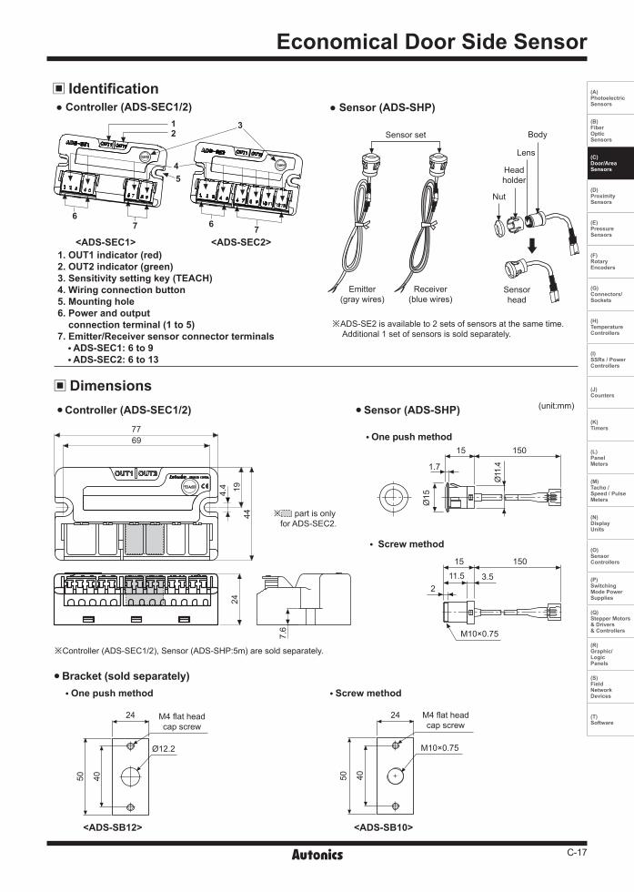
※ADS-SE2 is available to 2 sets of sensors at the same time. Additional 1 set of sensors is sold separately.
(unit:mm)
One push method
One push method Screw method
Screw method
<ADS-SB12> <ADS-SB10>
Controller (ADS-SEC1/2) Sensor (ADS-SHP)
Bracket (sold separately)
Ø12.2
24 M4 flat headcap screw
50 40
24
M10×0.75
M4 flat headcap screw
50 40
※Controller (ADS-SEC1/2), Sensor (ADS-SHP:5m) are sold separately.
※ part is only for ADS-SEC2.
Body
Sensorhead
Lens
Nut
Headholder
Sensor set
Emitter(gray wires)
Receiver(blue wires)
<ADS-SEC1> <ADS-SEC2>1. OUT1 indicator (red)2. OUT2 indicator (green)3. Sensitivity setting key (TEACH)4. Wiring connection button5. Mounting hole6. Power and output connection terminal (1 to 5)7. Emitter/Receiver sensor connector terminals ADS-SEC1: 6 to 9 ADS-SEC2: 6 to 13
Ø15
15 150
1.7
Ø11
.4
M10×0.75
15
3.511.5
150
2
Identification ● Controller (ADS-SEC1/2) ● Sensor (ADS-SHP)
Dimensions
12
4
3
5
77 66
7769
194.4
44
7.6
24

C-18
ADS-SE1/2
Controller1. Follow as below when adjusting wiring length. Cut off the wiring length as much as user needs. Connect the wire to the terminal after taking off the wire covering. It is easy to connect if soldering the end of the wires.
※Be sure of connecting wires in power off.※Follow the figure when cutting off the wires of sensor
head. If the cover of wire is taken off too much, it may cause damage to this product as the end of both wires is shorted.
Sensor1. Make a hole on the side post of auto door as
follows.
When not using the mounting bracket① One push method • Mounting hole for sensor head: Ø12.2±0.1mm • Panel thickness for sensor head: 1.5±0.5 mm② Screw method • Mounting hole for sensor head: M10×0.75mm • Panel thickness for sensor head: 1.5±0.5 mm
When using the mounting bracket① One push method • Through hole for sensor head: Ø13 to 14mm • Fixing screw hole for bracket: M4 Tap or Ø3.5mm② Screw method • Through hole for sensor head: Ø13 to 14mm • Fixing screw hole for bracket: M4 Tap or Ø3.5mm
※Check the mounting holes for the head of emitter and receiver are in parallel for the optical axes.
※Grind around the mounting holes drilled smoothly. It may hurt by sharp parts and cause malfunction by the inclined sensor head.
Caution for installing controller Fix a controller with 2 fixing bolts. Process the fixing holes of a controller by M4.
Refer to " Dimension" for the position of holes. Do not tighten bolts to fix a controller. The fixing holes of controller may be broken.
17mm
Outer shield wire
Inner covered wire
9mm
2. Match wires in the number of terminals and connect them.
Do not connect extended wire to the wire of sensor head. It may cause malfunction by noise.
Do not connect two wires or more to a terminal.
Connection method for power and output wires• Press a connecting button and wiring it. • It does not operate normally if the wiring is connected
conversely.• Make sure of connecting power wire to the terminal 4,
and 5. Otherwise, It may cause damage to this product.• Allowable diameter of power and output wires -Single and Stranded wire: 0.2 to 1.5 mm2
Installation
Emitter(gray)
Receiver(blue)Power
(12-24VAC/VDC)
Output (N.O.) (N.C.)
Emitter(gray)
Receiver(blue)
Output (N.O.) (N.C.)Power
(12-24VAC/VDC)
<1-channel>
<2-channel>
① ② ②①
C-19
Economical Door Side Sensor
(A) Photoelectric Sensors
(B) FiberOpticSensors
(C) Door/AreaSensors
(D) ProximitySensors
(E) PressureSensors
(F) RotaryEncoders
(G) Connectors/Sockets
(H)TemperatureControllers
(I)SSRs / PowerControllers
(J) Counters
(K) Timers
(L) PanelMeters
(M)Tacho /Speed / PulseMeters
(N)DisplayUnits
(O)SensorControllers
(P)SwitchingMode PowerSupplies
(Q)Stepper Motors & Drivers & Controllers
(R)Graphic/LogicPanels
(S)FieldNetworkDevices
(T) Software
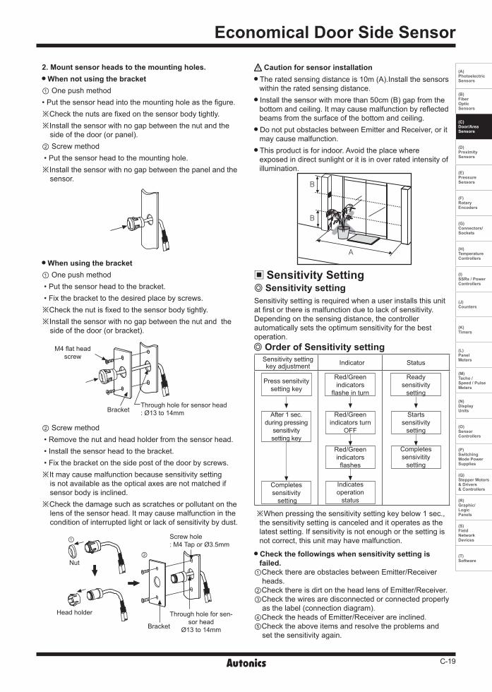
2. Mount sensor heads to the mounting holes. When not using the bracket① One push method• Put the sensor head into the mounting hole as the figure.※Check the nuts are fixed on the sensor body tightly. ※Install the sensor with no gap between the nut and the
side of the door (or panel).② Screw method • Put the sensor head to the mounting hole.※Install the sensor with no gap between the panel and the
sensor.
② Screw method • Remove the nut and head holder from the sensor head. • Install the sensor head to the bracket. • Fix the bracket on the side post of the door by screws.※It may cause malfunction because sensitivity setting
is not available as the optical axes are not matched if sensor body is inclined.
※Check the damage such as scratches or pollutant on the lens of the sensor head. It may cause malfunction in the condition of interrupted light or lack of sensitivity by dust.
When using the bracket① One push method • Put the sensor head to the bracket. • Fix the bracket to the desired place by screws.※Check the nut is fixed to the sensor body tightly.※Install the sensor with no gap between the nut and the
side of the door (or bracket).
Caution for sensor installation The rated sensing distance is 10m (A).Install the sensors within the rated sensing distance. Install the sensor with more than 50cm (B) gap from the bottom and ceiling. It may cause malfunction by reflected beams from the surface of the bottom and ceiling. Do not put obstacles between Emitter and Receiver, or it may cause malfunction. This product is for indoor. Avoid the place where exposed in direct sunlight or it is in over rated intensity of illumination.
M4 flat headscrew
BracketThrough hole for sensor head: Ø13 to 14mm
Screw hole: M4 Tap or Ø3.5mm
Through hole for sen-sor head
Ø13 to 14mmBracket
Nut
①
②
Head holder
Sensitivity Setting
Sensitivity setting is required when a user installs this unit at first or there is malfunction due to lack of sensitivity.Depending on the sensing distance, the controller automatically sets the optimum sensitivity for the best operation.
Check the followings when sensitivity setting is failed.
①Check there are obstacles between Emitter/Receiver heads.
②Check there is dirt on the head lens of Emitter/Receiver.③Check the wires are disconnected or connected properly
as the label (connection diagram).④Check the heads of Emitter/Receiver are inclined.⑤Check the above items and resolve the problems and
set the sensitivity again.
※When pressing the sensitivity setting key below 1 sec., the sensitivity setting is canceled and it operates as the latest setting. If sensitivity is not enough or the setting is not correct, this unit may have malfunction.
Sensitivity setting key adjustment Indicator Status
Press sensitvity setting key
After 1 sec. during pressing
sensitivity setting key
Completes sensitivity setting
Red/Green indicators
flashe in turn
Red/Green indicators turn
OFF
Indicates operation
status
Red/Green indicators flashes
Ready sensitivity
setting
Starts sensitivity
setting
Completes sensivitity
setting
Sensitivity setting
Order of Sensitivity setting
C-20
ADS-SE1/2
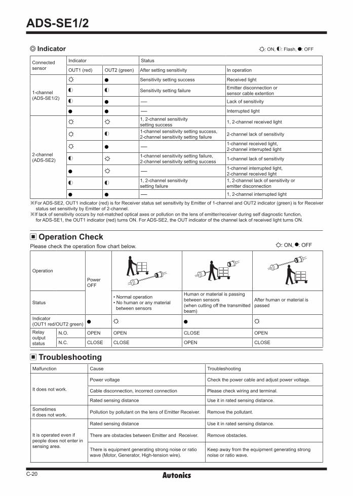
: ON, : OFF
Operation
Power OFF
Status• Normal operation• No human or any material between sensors
Human or material is passing between sensors (when cutting off the transmitted beam)
After human or material is passed
Indicator(OUT1 red/OUT2 green)
Relayoutput status
N.O. OPEN OPEN CLOSE OPEN
N.C. CLOSE CLOSE OPEN CLOSE
: ON, : Flash, : OFF
※For ADS-SE2, OUT1 indicator (red) is for Receiver status set sensitivity by Emitter of 1-channel and OUT2 indicator (green) is for Receiver status set sensitivity by Emitter of 2-channel.
※If lack of sensitivity occurs by not-matched optical axes or pollution on the lens of emitter/receiver during self diagnostic function, for ADS-SE1, the OUT1 indicator (red) turns ON. For ADS-SE2, the OUT indicator of the channel lack of received light turns ON.
Indicator
Connected sensor
Indicator Status
OUT1 (red) OUT2 (green) After setting sensitivity In operation
1-channel(ADS-SE1/2)
Sensitivity setting success Received light
Sensitivity setting failure Emitter disconnection or sensor cable extention
- Lack of sensitivity
- Interrupted light
2-channel(ADS-SE2)
1, 2-channel sensitivitysetting success 1, 2-channel received light
1-channel sensitivity setting success,2-channel sensitivity setting failure 2-channel lack of sensitivity
- 1-channel received light, 2-channel interrupted light
1-channel sensitivity setting failure,2-channel sensitivity setting success 1-channel lack of sensitivity
- 1-channel interrupted light,2-channel received light
1, 2-channel sensitivitysetting failure
1, 2-channel lack of sensitivity or emitter disconnection
- 1, 2-channel interrupted light
Operation CheckPlease check the operation flow chart below.
Troubleshooting Malfunction Cause Troubleshooting
It does not work.
Power voltage Check the power cable and adjust power voltage.
Cable disconnection, incorrect connection Please check wiring and terminal.
Rated sensing distance Use it in rated sensing distance.
Sometimes it does not work. Pollution by pollutant on the lens of Emitter Receiver. Remove the pollutant.
It is operated even if people does not enter in sensing area.
Rated sensing distance Use it in rated sensing distance.
There are obstacles between Emitter and Receiver. Remove obstacles.
There is equipment generating strong noise or ratio wave (Motor, Generator, High-tension wire).
Keep away from the equipment generating strong noise or ratio wave.

C-21
Economical Door Side Sensor
(A) Photoelectric Sensors
(B) FiberOpticSensors
(C) Door/AreaSensors
(D) ProximitySensors
(E) PressureSensors
(F) RotaryEncoders
(G) Connectors/Sockets
(H)TemperatureControllers
(I)SSRs / PowerControllers
(J) Counters
(K) Timers
(L) PanelMeters
(M)Tacho /Speed / PulseMeters
(N)DisplayUnits
(O)SensorControllers
(P)SwitchingMode PowerSupplies
(Q)Stepper Motors & Drivers & Controllers
(R)Graphic/LogicPanels
(S)FieldNetworkDevices
(T) Software
Caution For Using 1. When two channels of sensor are mounted closely, it
may cause mutual interference by the emitter of other sensor. Therefore, please install them to avoid the interference by exchanging the head of Emitter and Receiver and by keeping the distance between the heads in more than 50cm.
2. When sensor head is installed on the ceiling or floor closely, it may cause malfunction by receiving the reflected beam. Therefore, please install it by keeping the suitable height (more than approx. 50cm) from the ceiling or floor.
3. When the target is a translucent or small object (Max. Ø15mm) it may not detect as the light transmits them.
4. When wire sensor in the same pipe laying with the high-tension wire or power line, it may cause malfunction. Therefore, please use separated wiring or pipe laying.
5. What sensor is used in much dusty or corroded place, it may cause malfunction. Please avoid these places when installing.
6. When making the length of the wiring (power wire or output wire) long, it may cause malfunction by surge etc.
7. When the lens of sensor head is polluted by dust etc., please clean it by dried cloth slightly.Do not use organic solvent like thinner.
8. When switching mode power supply is used as the source of supplying power, please ground F.G. terminal and install a condenser for removing noise between 0V and F.G. terminal as following drawing.
Switchingmode
power supply(S.M.P.S.)
Door sidesensor
(Controller part)
Power12-24VDC
F.G.
PowerC (0.001 to 0.1㎌/400V): Condensor for removing noise
Frame