
Adoptation of MV PLC system using DCSK · PDF fileAdoptation of MV PLC system using DCSK...
6
Adoptation of MV PLC system using DCSK modulation Byungseok Park, Younghoon Lim, Taeyoung Lee, Younglim Choi, DuckHwa Hyun, Donghee Yoo *C&C Group, Power System Lab. KEPRI(Korea Electric Power Research Institute) E-mail: [email protected] Abstract Although Electric utility company requires automotive MV distribution system, it is hard to get fine communication network that must be offered with cost effective and reliable performance. MV PLC network has many advantages in aspect of administration, maintenance, easy and rapid installation. Now it is necessary to communicate with DAS (Distribution Automation System) in Korea. So, we design and develop MV PLC System for DAS. This PLC system operates under 400kHz frequency with DCSK modulation(based on Chirp SS) and shows 9.6kbps performance. Also, we investigate ceramic type MV coupling capacitor that has small size and low signal attenuation. We test MV PLC system in real MV field in Korea and show successful communication performance without retransmission in 10 km real field and 18 km test-bed under very high noise environment. This system will be adopted to distribution automation system and AMR(Automatic Meter Reading) In this paper, we introduce the MV PLC system's architecture, technique and experimental characteristics, such as impedance, attenuation and noise of Korea MV system. 1. Introduction As the growth of electric distribution system, utility company desires for intelligent monitoring and control system for distribution system. So, various remote control systems such as DAS, transformer monitoring system and power quality monitoring system were developed and tested in real field. These systems require cost effective and moderately reliable communication link. However, the distribution system has long distance range about maximum 40km and various and poor outdoor environment. In Kepco(Korea electric power company), communication link of various kinds was introduced and applied for automotive and remote system for power distribution system. These communication links consist of TRS(Trunking Radio System), PCS(Personal Communication System), leased line, and optical link. Some links are very reliable and high speed performance, but has very high construction or operating cost. And the others are some cheap but has low reliability such as radio shadow region. In this paper, we investigate MV PLC system to assist or replace existing communication link. . 2. Basic architecture Architecture of MV PLC system is basically equal to normal LV PLC modem. However the required specification is much different. Coupling capacitor must endure 22.9kV Medium Voltage and higher surge such as induced lightening, switch on/off impulse than low voltage environment. The basic transmission procedure is described as follow. Digital data from FRTU(Front Remote Terminal Unit) is sent to MCU(Micro Control Unit) through UART chip and then modulated to analog signal. Analog signal is amplified for long distance transmission. Impedance matching circuit reduces the reflection of signal at injecting to powerline. Coupling capacitor isolates transmit signal and protects PLC modem from power source. Surge arrester part protects PLC modem from high frequency high voltage power-line impulse signal. Figure 1 shows basic structure of MV PLC system. Fig. 1. The basic structure of MV PLC system 22.9kV MV DL FRTU MCU UART Coupling Capacitor Surge Arrester AMP Circuit Breaker Modulation Impedance Matching
Transcript of Adoptation of MV PLC system using DCSK · PDF fileAdoptation of MV PLC system using DCSK...

Adoptation of MV PLC system using DCSK modulation
Byungseok Park, Younghoon Lim, Taeyoung Lee, Younglim Choi, DuckHwa Hyun, Donghee Yoo
*C&C Group, Power System Lab. KEPRI(Korea Electric Power Research Institute)
E-mail: [email protected]
Abstract Although Electric utility company requires automotive MV distribution system, it is hard to get fine communication network that must be offered with cost effective and reliable performance. MV PLC network has many advantages in aspect of administration, maintenance, easy and rapid installation. Now it is necessary to communicate with DAS (Distribution Automation System) in Korea. So, we design and develop MV PLC System for DAS. This PLC system operates under 400kHz frequency with DCSK modulation(based on Chirp SS) and shows 9.6kbps performance. Also, we investigate ceramic type MV coupling capacitor that has small size and low signal attenuation. We test MV PLC system in real MV field in Korea and show successful communication performance without retransmission in 10 km real field and 18 km test-bed under very high noise environment. This system will be adopted to distribution automation system and AMR(Automatic Meter Reading) In this paper, we introduce the MV PLC system's architecture, technique and experimental characteristics, such as impedance, attenuation and noise of Korea MV system. 1. Introduction As the growth of electric distribution system, utility company desires for intelligent monitoring and control system for distribution system. So, various remote control systems such as DAS, transformer monitoring system and power quality monitoring system were developed and tested in real field. These systems require cost effective and moderately reliable communication link. However, the distribution system has long distance range about maximum 40km and various and poor outdoor environment. In Kepco(Korea electric power company), communication link of various kinds was introduced and applied for automotive and remote system for power distribution system. These communication links consist of
TRS(Trunking Radio System), PCS(Personal Communication System), leased line, and optical link. Some links are very reliable and high speed performance, but has very high construction or operating cost. And the others are some cheap but has low reliability such as radio shadow region. In this paper, we investigate MV PLC system to assist or replace existing communication link. . 2. Basic architecture
Architecture of MV PLC system is basically equal to normal LV PLC modem. However the required specification is much different. Coupling capacitor must endure 22.9kV Medium Voltage and higher surge such as induced lightening, switch on/off impulse than low voltage environment. The basic transmission procedure is described as follow. Digital data from FRTU(Front Remote Terminal Unit) is sent to MCU(Micro Control Unit) through UART chip and then modulated to analog signal. Analog signal is amplified for long distance transmission. Impedance matching circuit reduces the reflection of signal at injecting to powerline. Coupling capacitor isolates transmit signal and protects PLC modem from power source. Surge arrester part protects PLC modem from high frequency high voltage power-line impulse signal. Figure 1 shows basic structure of MV PLC system.
Fig. 1. The basic structure of MV PLC system
22.9kV
MV DL
FRTU
MCU
UART
Coupling Capacitor
Surge Arrester
AMP
Circuit Breaker
Modulation
Impedance Matching
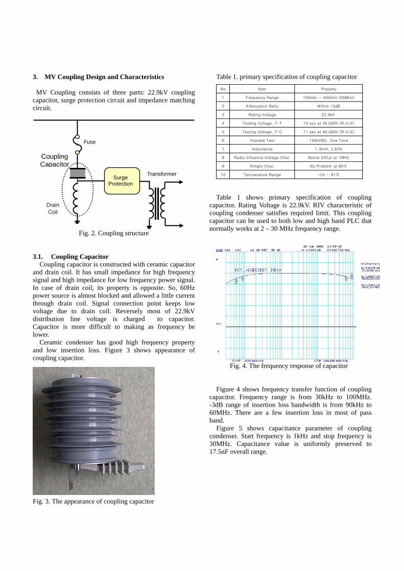
3. MV Coupling Design and Characteristics
MV Coupling consists of three parts: 22.9kV coupling
.1. Coupling Capacitor u tructed with ceramic capacitor
an
ic condenser has good high frequency property an
apacitor
able 1 shows primary specification of coupling ca
Figure 4 shows frequency transfer function of coupling ca
5 shows capacitance parameter of coupling co
capacitor, surge protection circuit and impedance matching circuit.
Fig. 2. Coupling structure
3
Co pling capacitor is consd drain coil. It has small impedance for high frequency
signal and high impedance for low frequency power signal. In case of drain coil, its property is opposite. So, 60Hz power source is almost blocked and allowed a little current through drain coil. Signal connection point keeps low voltage due to drain coil. Reversely most of 22.9kV distribution line voltage is charged to capacitor. Capacitor is more difficult to making as frequency be lower.
Ceramd low insertion loss. Figure 3 shows appearance of
coupling capacitor.
Table 1. primary specification of coupling c
Fig. 3. The appearance of coupling capacitor
Tpacitor. Rating Voltage is 22.9kV. RIV characteristic of
coupling condenser satisfies required limit. This coupling capacitor can be used to both low and high band PLC that normally works at 2 – 30 MHz frequency range.
Fig. 4. The frequency response of capacitor
pacitor. Frequency range is from 30kHz to 100MHz. -3dB range of insertion loss bandwidth is from 90kHz to 60MHz. There are a few insertion loss in most of pass band.
Figurendenser. Start frequency is 1kHz and stop frequency is
30MHz. Capacitance value is uniformly preserved to 17.5nF overall range.
Surge Protection
Transformer
Drain
Coupling
Coil
Capacitor
Fuse
No Item Property
1 Frequency Range 100kHz ~ 450kHz (30MHz)
2 Attenuation Ratio Within -3dB
3 Rating Voltage 22.9kV
4 Testing Voltage, T-T 10 sec at 40,000V (R.V*2)
5 Testing Voltage, T-C 11 sec at 40,000V (R.V*2)
6 Impulse Test 150kVBIL, One Time
7 Inductance 1.3mH, ±30%
8 Radio Influence Voltage Char. Below 250 at 1MHz
9 Airtight Char. No Problem at 80
10 Temperature Range -25 ~ 81

Fig. 5. The capacitance of coupling condenser 3.2. Impedance matching circuit
In transmission line, impedance matching cannot be
emphasized of important too much. Do not password-protect it. However the impedance matching in PLC system is very difficult due to many branch and numerous kind of electric device. Designed system has 5 variable impedance point from 89Ω to 800Ω.
Table 2. Impedance matching step
Fig. 6. Impedance matching transformer Matching transformer uses transmission line transformer
structure[1]. This transformer is simple and easy for high power signal.
4. Modulation Module Designed system uses Chirp Spread Spectrum modulation method. The most primitive transmit signal is the one unit symbol signal. This unit symbol is matched to 5 bit data, each bit pattern assigns start point of the unit symbol. In Figure 7, each UST signal is same, but start position just different[2].
Fig. 7. DCSK modulation skim
AC
Line
Protect
&
EMI Filter
PowerSupply
CouplingCKT
BalancedDifferential Amp
Secondary 1st Filter110 k ~ 195 kHz
Transmit DriveCircuit
Pre Filter100 K ~ 400 kHz
Amp &Comparator
RS -232CDriver
MAC ProtocolCPU Physical Transceiver
Secondary 2nd Filter205 k ~ 285 kHz
Amp &Comparator
Secondary 3rd Filter305 k ~ 395 kHz
Amp &Comparator
Input Terminal Output Terminal Impedance Matching Ratio
A D 50 : 89
D 50 : 200
E 50 : 112
E 50 : 450
D 50 : 800
B
C
Fig. 8. The Modulation Module Structure Figure 8 shows the whole block diagram of modulation part. Each data is duplicated to 3 frequency band signals and transmitted. Modem at the receive correlates and compares 3 band signals and then decides suitable bit pattern. Table 3. The specification of Modulation part
Item specification Code Modulation DCSK modulation Physical Modulation Spread Spectrum Carrier Frequency 100kHz ~ 400kHz Media Access Control CSMA/CA Error Correction 16Bit CRC, 8Bit CRC Interface RS-232

Baud Rate 4800bps ~ 19200bps TRX Speed SM Standard Mode 7.5kbps TRX Speed RM Robost Mode 5kbps TRX Speed ERM Extremly Robost Mode 1.25kbps
5. Field Test 5.1. Distribution System of Test Bed
The MV Distribution system in Korea is Y type connection(3 Phase 4 line) power system having multiple ground. Rating voltage is 22.9kV and wire to ground voltage is 13.2kV. Developed system was tested in Go-Chang Power system test bed. Go-Chang test bed directly injected from station of nuclear power plant that has about 10 km distance. Test bed constructed with dual layer closed loop power line about 4km length. Multi-path SW allows test bed to be configured several topology. For the long distance PLC communication test, the one end is shorted, the other end is opened. As shown in Figure 9, 18km length of testing power line is constructed.
Fig. 9. MV PLC communication test in test bed
5.2. Developed MV PLC system
Developed system can change transmit signal power 10W or 25W and has manually variable impedance selection switch. Figure 11 shows the spectrum of modulated signal before amplifier stage. Signal spectrum power is uniformly flat over the whole frequency range.
Fig. 10. MV PLC transceiver
Fig. 11. The spectrum of transmit signal
Fig. 12. Installed coupling capacitor on power pole

Fig. 13. The envelop of power-line noise
Fig. 14. The received signal envelop(A->C)
Fig. 15. The received signal enveolp(A->B)
100 200 300 400 500
-25
-20
-15
-10
-5
0
Frequency[kHz]
20 50 112 200 450 800
Fig. 16. Reflection Signal vs matching transformer
5.3 Measured Results In this subsection, we present the measured results in the MV PLC system with 22.9kV. The main focus of this investigation is the sensitivity of the received signal on different levels of frequency and transmission distance. Fig. 13 represents the envelope of power-line noise as the function of frequency. Most of the noise signal is mainly distributed in –40dB. We observed that the noise amplitude at between 100kHz and 200kHz is higher than that at above 200kHz. Fig 14 and 15 show the received signal envelope at B and C point. We observed that when the frequency is changed, the degree of the fluctuation of the received signal envelope is severe at below 200kHz and above 600kHz. The condition of the signal in Fig. 14 is better than that in Fig. 15. Therefore we can obtain the sufficient signal level for communication at short distance. Also through the measured results, we can identify that the received signal envelope depends on the frequency and the transmission distance. In Fig. 16, we confirmed the relation between the frequency and matching transformer. The condition of the reflection signal at above 350kHz is good regardless of the matching transformer. However, when the value of the matching transformer decreases, the state of signal grows worse at below 200kHz. 6. Conclusions MV PLC system is very attractive solution for remote monitoring and control of distribution system. In this paper, we discuss MV PLC system using DCSK modulation. DCSK modulation is strong for noise. We examined in real field test. Developed system shows excellent performance for long distance data communication test.

References [1] [2]
Jerry Sevick, “Transmission Line Transformers,” 4th ed. Novell Publishing, 2001. Dan raphaeli, US patent 6,064,695, may 16, 2000


![Design and implementation of Haar wavelet packet ...Sep 05, 2018 · DCSK [8] and multiuser OFDM-based DCSK (MU Research Article Abstract Efficient design and implementation of Haar](https://static.fdocuments.in/doc/165x107/5fb251f9ec6a105ba269b811/design-and-implementation-of-haar-wavelet-packet-sep-05-2018-dcsk-8-and.jpg)