ADL Founda on - Pacific Crest · Pacifi c Crest ADL founda on Integrator’s Guide iii ... 12 –...
19
ADL FoundaƟon Radio Modem Integrator’s Guide
-
Upload
truongquynh -
Category
Documents
-
view
227 -
download
3
Transcript of ADL Founda on - Pacific Crest · Pacifi c Crest ADL founda on Integrator’s Guide iii ... 12 –...

ADL Founda on
Radio ModemIntegrator’s Guide
Pacifi c Crest ADL founda on Integrator’s Guide i
No cePacifi c Crest shall not be liable for errors contained herein or for incidental consequen al damages in connec on with the furnishing, performance, or use of this material.
This document contains proprietary informa on that is protected by copyright. All rights are reserved. No part of this document may be photocopied, reproduced, or translated into another language without the prior wri en consent of Pacifi c Crest.
The informa on contained in this document is subject to change without no ce.
Cau ons and Warnings Throughout this manual this symbol is used to indicate cau on or warning. Please pay par cular a en on to these items to assure safe and reliable opera on of your radio modem product.
License required prior to opera on of radio communica on equipment. Specifi ca ons are subject to change without no fi ca on.
Adapta on, or transla on of this manual is prohibited without prior wri en permission of Pacifi c Crest, except as allowed under the copyright laws.
Pacifi c Crest510 DeGuigne DriveSunnyvale, CA 94085(408) 481-8070(408) 481-8984 Faxinfo@Pacifi cCrest.com www.Pacifi cCrest.com
December 2011
©2011 Pacifi c Crest. All rights reserved. PORON is a licensed trademark of Rogers Corpora on. SATEL is a registered trademark of SATEL Oy. TRIMMARK and TRIMTALK are trademarks of Trimble Naviga on Ltd. All trademarks are the prop-erty of their respec ve owners.
!
Pacifi c Crest ADL founda on Integrator’s Guide ii
Contents
Introduc on . . . . . . . . . . . . . . . . . . . . . . . . . . . . . . . . . . . . . . . . 1
Main Components . . . . . . . . . . . . . . . . . . . . . . . . . . . . . . . . . . . . . . . . . . . . . . . . . . 1
Ge ng Started . . . . . . . . . . . . . . . . . . . . . . . . . . . . . . . . . . . . . . 2
Compliance . . . . . . . . . . . . . . . . . . . . . . . . . . . . . . . . . . . . . . . . . . . . . . . . . . . . . . . . 4
Compa bility . . . . . . . . . . . . . . . . . . . . . . . . . . . . . . . . . . . . . . . . . . . . . . . . . . . . . . 4
Protocols and Modes of Opera on . . . . . . . . . . . . . . . . . . . . . 5
Electrical Considera ons . . . . . . . . . . . . . . . . . . . . . . . . . . . . . . 6
Power Supply . . . . . . . . . . . . . . . . . . . . . . . . . . . . . . . . . . . . . . . . . . . . . . . . . . . . . . 6
Data Interface . . . . . . . . . . . . . . . . . . . . . . . . . . . . . . . . . . . . . . . . . . . . . . . . . . . . . . 6
LED Drivers . . . . . . . . . . . . . . . . . . . . . . . . . . . . . . . . . . . . . . . . . . . . . . . . . . . . . . . . 7
Error Codes . . . . . . . . . . . . . . . . . . . . . . . . . . . . . . . . . . . . . . . . . . . . . . . . . . . . . . . . 7
Shielding Considera ons . . . . . . . . . . . . . . . . . . . . . . . . . . . . . . . . . . . . . . . . . . . . . 8
Frequency Planning . . . . . . . . . . . . . . . . . . . . . . . . . . . . . . . . . . . . . . . . . . . . . . . . . 8
Mechanical Considera ons . . . . . . . . . . . . . . . . . . . . . . . . . . . . 9
EMI interferers . . . . . . . . . . . . . . . . . . . . . . . . . . . . . . . . . . . . . . . . . . . . . . . . . . . . . 9
Shock and Vibra on . . . . . . . . . . . . . . . . . . . . . . . . . . . . . . . . . . . . . . . . . . . . . . . . . 9
Thermal Transfer. . . . . . . . . . . . . . . . . . . . . . . . . . . . . . . . . . . . . . . . . . . . . . . . . . . . 9
Materials . . . . . . . . . . . . . . . . . . . . . . . . . . . . . . . . . . . . . . . . . . . . . . . . . . . . . . . . . .10
Service and Support . . . . . . . . . . . . . . . . . . . . . . . . . . . . . . . . . 10
Philosophy . . . . . . . . . . . . . . . . . . . . . . . . . . . . . . . . . . . . . . . . . . . . . . . . . . . . . . . .10
Phone/Internet Support . . . . . . . . . . . . . . . . . . . . . . . . . . . . . . . . . . . . . . . . . . . . .10
Warranty . . . . . . . . . . . . . . . . . . . . . . . . . . . . . . . . . . . . . . . . . . . 10
One-Year Limited Warranty . . . . . . . . . . . . . . . . . . . . . . . . . . . . . . . . . . . . . . . . . . .10
Exclusions . . . . . . . . . . . . . . . . . . . . . . . . . . . . . . . . . . . . . . . . . . . . . . . . . . . . . . . . .10
Appendix A - Moun ng Guide . . . . . . . . . . . . . . . . . . . . . . . . . 11
Standard Enclosure . . . . . . . . . . . . . . . . . . . . . . . . . . . . . . . . . . . . . . . . . . . . . . . . .11
Pacifi c Crest ADL founda on Integrator’s Guide iii
Appendix B - Cables and Connectors . . . . . . . . . . . . . . . . . . . . 12
Value-Added Cable Products . . . . . . . . . . . . . . . . . . . . . . . . . . . . . . . . . . . . . . . . .12
Interface Connector . . . . . . . . . . . . . . . . . . . . . . . . . . . . . . . . . . . . . . . . . . . . . . . . .12
RF Connector . . . . . . . . . . . . . . . . . . . . . . . . . . . . . . . . . . . . . . . . . . . . . . . . . . . . . .12
Appendix C - Technical Specifi ca ons . . . . . . . . . . . . . . . . . . . 12
General . . . . . . . . . . . . . . . . . . . . . . . . . . . . . . . . . . . . . . . . . . . . . . . . . . . . . . . . . . .12
Radio Specifi ca ons . . . . . . . . . . . . . . . . . . . . . . . . . . . . . . . . . . . . . . . . . . . . . . . . .12
Modem . . . . . . . . . . . . . . . . . . . . . . . . . . . . . . . . . . . . . . . . . . . . . . . . . . . . . . . . . . .13
Environmental. . . . . . . . . . . . . . . . . . . . . . . . . . . . . . . . . . . . . . . . . . . . . . . . . . . . . .13
Mechanical . . . . . . . . . . . . . . . . . . . . . . . . . . . . . . . . . . . . . . . . . . . . . . . . . . . . . . . .14
Appendix E – ADL Test . . . . . . . . . . . . . . . . . . . . . . . . . . . . . . . . 14
Descrip on . . . . . . . . . . . . . . . . . . . . . . . . . . . . . . . . . . . . . . . . . . . . . . . . . . . . . . . .14
Usage . . . . . . . . . . . . . . . . . . . . . . . . . . . . . . . . . . . . . . . . . . . . . . . . . . . . . . . . . . . . .14
Run Test . . . . . . . . . . . . . . . . . . . . . . . . . . . . . . . . . . . . . . . . . . . . . . . . . . . . . . . . . . .14
Pacifi c Crest ADL founda on Integrator’s Guide 1
Introduc onThis guide provides informa on concerning the integra on of the Advanced Data Link (ADL) Founda on radio modem transceivers - Model numbers ADLF-1 (390 to 430 MHz) and ADLF-2 (430 to 470 MHz) - into your product. This guide should be used in conjunc on with the ADLCONF User’s Guide – Dealer Version that should be referenced for general informa on concerning the confi gura on of ADL radio modems, and also for detailed programming informa on.
The ADL Founda on is a general-purpose radio modem transceiver that is compa ble with both the ADL and the Posi oning Data Link (PDL) product families of radio modems. The ADL Founda on transceiver is designed specifi cally for integra on into exis ng or new products. Its small size, light weight and power effi cient opera on provide superior performance in embedded systems.
A variety of confi gura ons are available to ease the integra on task, including CMOS or RS-232 data interface, a variety of I/O connectors and two frequency bands covering the 390-430 and 430-470 MHz ranges. The ADL RXO, a receive-only radio module, is described in a separate Integrator’s Guide available from Pacifi c Crest.
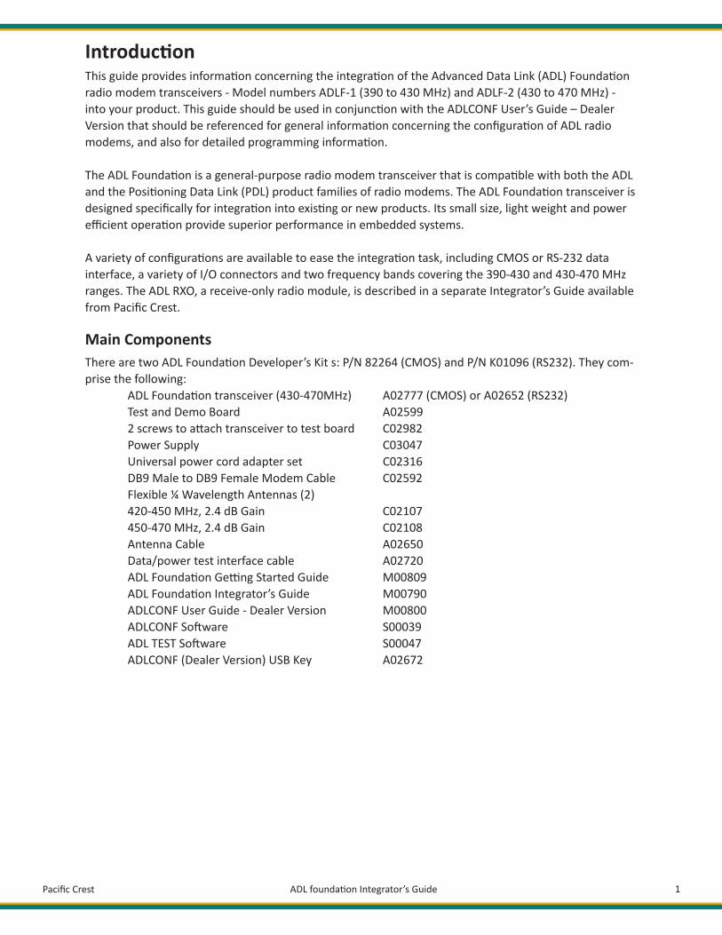
Main ComponentsThere are two ADL Founda on Developer’s Kit s: P/N 82264 (CMOS) and P/N K01096 (RS232). They com-prise the following: ADL Founda on transceiver (430-470MHz) A02777 (CMOS) or A02652 (RS232) Test and Demo Board A02599 2 screws to a ach transceiver to test board C02982 Power Supply C03047 Universal power cord adapter set C02316 DB9 Male to DB9 Female Modem Cable C02592 Flexible ¼ Wavelength Antennas (2) 420-450 MHz, 2.4 dB Gain C02107 450-470 MHz, 2.4 dB Gain C02108 Antenna Cable A02650 Data/power test interface cable A02720 ADL Founda on Ge ng Started Guide M00809 ADL Founda on Integrator’s Guide M00790 ADLCONF User Guide - Dealer Version M00800 ADLCONF So ware S00039 ADL TEST So ware S00047 ADLCONF (Dealer Version) USB Key A02672

Pacifi c Crest ADL founda on Integrator’s Guide 2
Ge ng Started
Cau on: ADL Founda on transceiver must be handled with care during installa on. Remove the transceiver from its protec ve bag only in an ESD safe area.
To set up the hardware components, follow these steps:1. Plug the ADL Founda on transceiver into the I/O-test board’s 20-pin connector2. Secure the module to the I/O-test board using the provided screws3. A ach the antenna cable to the ADL Founda on transceiver4. A ach one of the two antennas (whichever matches your licensed frequency) to the antenna cable5. A ach the PC interface cable to the I/O-test board’s 9-pin UART connector (see diagram below)6. A ach the PC interface cable to a serial port on your PC7. A ach the wall cable to the AC/DC adapter and select the proper plug from the adapter kit8. A ach the AD/DC adapter’s tubular plug to the power jack on the I/O-test board9. Plug in the ADLCONF (Dealer’s Version) USB key on your PC10. Install ADLCONF (h p://www.pacifi ccrest.com/support.php?page=updates) on your PC, but do not launch the program yet11. Download and install the latest Sen nel driver for the USB driver from h p://www.safenet-inc.com/support-downloads/sen nel-drivers12. Launch ADLCONF and refer to its user guide for instruc ons on connec ng to the ADL Founda on transceiver
!
Figure 1 - ADL Founda on Developer’s Kit
Pacifi c Crest ADL founda on Integrator’s Guide 3
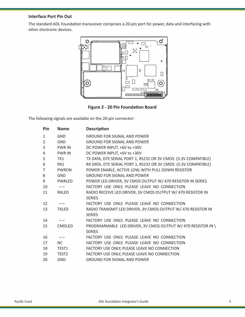
Interface Port Pin OutThe standard ADL Founda on transceiver comprises a 20-pin port for power, data and interfacing with other electronic devices.
Figure 2 - 20 Pin Founda on Board
The following signals are available on the 20-pin connector:
Pin Name Descrip on 1 GND GROUND FOR SIGNAL AND POWER 2 GND GROUND FOR SIGNAL AND POWER 3 PWR IN DC POWER INPUT, +6V to +30V 4 PWR IN DC POWER INPUT, +6V to +30V 5 TX1 TX DATA, DTE SERIAL PORT 1, RS232 OR 3V CMOS (3.3V COMPATIBLE) 6 RX1 RX DATA, DTE SERIAL PORT 1, RS232 OR 3V CMOS (3.3V COMPATIBLE) 7 PWRON POWER ENABLE, ACTIVE LOW, WITH PULL DOWN RESISTOR 8 GND GROUND FOR SIGNAL AND POWER 9 PWRLED POWER LED DRIVER, 3V CMOS OUTPUT W/ 470 RESISTOR IN SERIES 10 – – FACTORY USE ONLY, PLEASE LEAVE NO CONNECTION 11 RXLED RADIO RECEIVE LED DRIVER, 3V CMOS OUTPUT W/ 470 RESISTOR IN SERIES 12 – – FACTORY USE ONLY, PLEASE LEAVE NO CONNECTION 13 TXLED RADIO TRANSMIT LED DRIVER, 3V CMOS OUTPUT W/ 470 RESISTOR IN SERIES 14 – – FACTORY USE ONLY, PLEASE LEAVE NO CONNECTION 15 CMDLED PROGRAMMABLE LED DRIVER, 3V CMOS OUTPUT W/ 470 RESISTOR IN \ SERIES 16 – – FACTORY USE ONLY, PLEASE LEAVE NO CONNECTION 17 NC FACTORY USE ONLY, PLEASE LEAVE NO CONNECTION 18 TEST1 FACTORY USE ONLY, PLEASE LEAVE NO CONNECTION 19 TEST2 FACTORY USE ONLY, PLEASE LEAVE NO CONNECTION 20 GND GROUND FOR SIGNAL AND POWER
Pacifi c Crest ADL founda on Integrator’s Guide 4
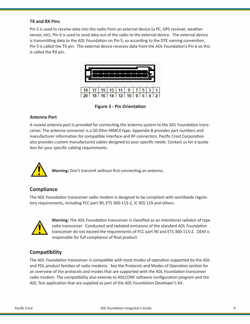
TX and RX PinsPin 5 is used to receive data into the radio from an external device (a PC, GPS receiver, weather sensor, etc). Pin 6 is used to send data out of the radio to the external device. The external device is transmi ng data to the ADL Founda on on Pin 5, so according to the DTE naming conven on, Pin 5 is called the TX pin. The external device receives data from the ADL Founda on’s Pin 6 so this is called the RX pin.
Figure 3 - Pin Orienta on
Antenna Port A coaxial antenna port is provided for connec ng the antenna system to the ADL Founda on trans-ceiver. The antenna connector is a 50-Ohm MMCX type. Appendix B provides part numbers and manufacturer informa on for compa ble interface and RF connectors. Pacifi c Crest Corpora on also provides custom manufactured cables designed to your specifi c needs. Contact us for a quota- on for your specifi c cabling requirements.
Warning: Don’t transmit without fi rst connec ng an antenna.
!
Compliance The ADL Founda on transceiver radio modem is designed to be compliant with worldwide regula-tory requirements, including FCC part 90, ETS 300-113-2, IC RSS 119 and others.
Warning: The ADL Founda on transceiver is classifi ed as an inten onal radiator of type radio transceiver. Conducted and radiated emissions of the standard ADL Founda on transceiver do not exceed the requirements of FCC part 90 and ETS 300-113-2. OEM is responsible for full compliance of fi nal product.
Compa bility The ADL Founda on transceiver is compa ble with most modes of opera on supported by the ADL and PDL product families of radio modems. See the Protocols and Modes of Opera on sec on for an overview of the protocols and modes that are supported with the ADL Founda on transceiver radio modem. The compa bility also extends to ADLCONF so ware confi gura on program and the ADL Test applica on that are supplied as part of the ADL Founda on Developer’s Kit.
!
Pacifi c Crest ADL founda on Integrator’s Guide 5
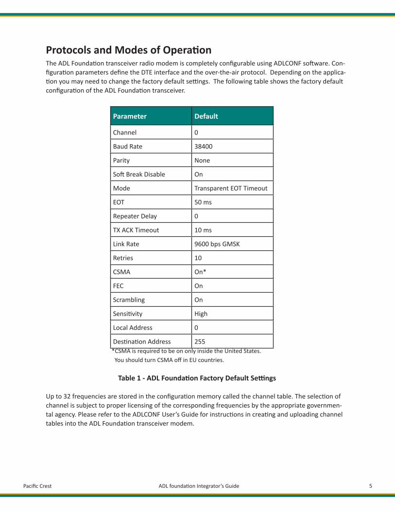
Protocols and Modes of Opera on The ADL Founda on transceiver radio modem is completely confi gurable using ADLCONF so ware. Con-fi gura on parameters defi ne the DTE interface and the over-the-air protocol. Depending on the applica- on you may need to change the factory default se ngs. The following table shows the factory default
confi gura on of the ADL Founda on transceiver.
Parameter Default
Channel 0
Baud Rate 38400
Parity None
So Break Disable On
Mode Transparent EOT Timeout
EOT 50 ms
Repeater Delay 0
TX ACK Timeout 10 ms
Link Rate 9600 bps GMSK
Retries 10
CSMA On*
FEC On
Scrambling On
Sensi vity High
Local Address 0
Des na on Address 255 *CSMA is required to be on only inside the United States. You should turn CSMA off in EU countries.
Table 1 - ADL Founda on Factory Default Se ngs
Up to 32 frequencies are stored in the confi gura on memory called the channel table. The selec on of channel is subject to proper licensing of the corresponding frequencies by the appropriate governmen-tal agency. Please refer to the ADLCONF User’s Guide for instruc ons in crea ng and uploading channel tables into the ADL Founda on transceiver modem.

Pacifi c Crest ADL founda on Integrator’s Guide 6
The ADL Founda on transceiver modem supports mul ple protocols and modes of opera on including:
• Transparent with EOT Timeout• Transparent with EOT Character• Transparent FST• Packet Switched• TRIMTALK™ 450S• TRIMTALK II/IIE• TT450S HW• TRIMMARK™ 3• SATEL®
Refer to the ADLCONF User’s Guide for a detailed descrip on.
Electrical Considera ons Power Supply The ADL Founda on transceiver has a power supply connec on on both Pin 3 and Pin 4 of the interface connector. Pins 1, 2, 8 and 20 are connec ons to both power ground and RS-232 interface signal grounds. Note that these pins are ed to a common point on the ADL Founda on transceiver. If there is a poten- al for a ground path current loop due to improper power applica on, we recommend a fusible link be
inserted in the signal ground to protect the ADL Founda on transceiver.
ADL Founda on transceiver modems are designed to operate with unregulated DC voltage levels be-tween 6 and 30 VDC. The power supply must be capable of sourcing 1.6A.
Note: The ADL Founda on Developer Kit includes a 5 V DC power supply. This provides suffi -cient power for development and tes ng purposes. ADLCONF so ware allows you to confi g-ure an ADL radio modem to warn the user when input voltage falls below a certain level. The default level is 9 V DC. Because the Developer Kit power supply provides only 5 V DC, you should not enable this feature in ADLCONF and then confi gure your test module.
Data Interface ADL Founda on transceiver provides two serial ports. One is a data port, which has a simple 3-wire CMOS or RS-232 electrical interface with signals for transmi ng data to and receiving data from the ADL Founda on transceiver, and for providing a reference ground for the TX (Pin 5) and RX (Pin 6) signals. The other is a debug port (TX is Pin 14 and RX is Pin 12). ADL Founda on transceiver uses this port to send out debug informa on for trouble shoo ng purpose. The CMOS/RS-232 op on is set by Pacifi c Crest prior to shipping.
Note: We defi ne TX and RX as a DTE port. In other words, an external device transmits data to the radio modem’s TX pin (Pin 5) and receives data from the radio modem’s RX pin (Pin 6).

Pacifi c Crest ADL founda on Integrator’s Guide 7
CMOS Input/Output Protec on Circuitry The TX signal terminates into a CMOS input port on the ADL Founda on transceiver and should be driven externally or pulled to ground through a 10 kΩ resistor. The absolute maximum voltage applied to the TX signal is -0.3 V to 3.3 V.
The RX and DCD signals are CMOS outputs. Note that loading the RX and DCD signals increases the power consump on of the ADL Founda on transceiver and these should be limited to no more than 2.5 mA each to maintain performance across the temperature range.
Cau on: Internal circuitry protects the inputs and outputs against damage caused by high sta c voltages or electric fi elds; however, normal precau ons are necessary to avoid applica- on of any voltage higher than the maximum-rated voltages.
LED Drivers The ADL Founda on transceiver provides access to four func on-specifi c LED drivers. Figure 2 shows the product with a 20 pin connector. Table 4 shows the pin-out and func on of the four LED drivers.
Pin Func on Descrip on
9 PWR LED Power LED Driver
11 RX LED Radio Receive LED driver
13 TX LED Radio transmit LED driver
15 CMD LED Programmable LED driver
Table 2 - Pin-outs for the LED driver port
The LED drivers are designed to provide approximately 2 mA. This drive level requires that only high-effi ciency LEDs be used with the drivers.
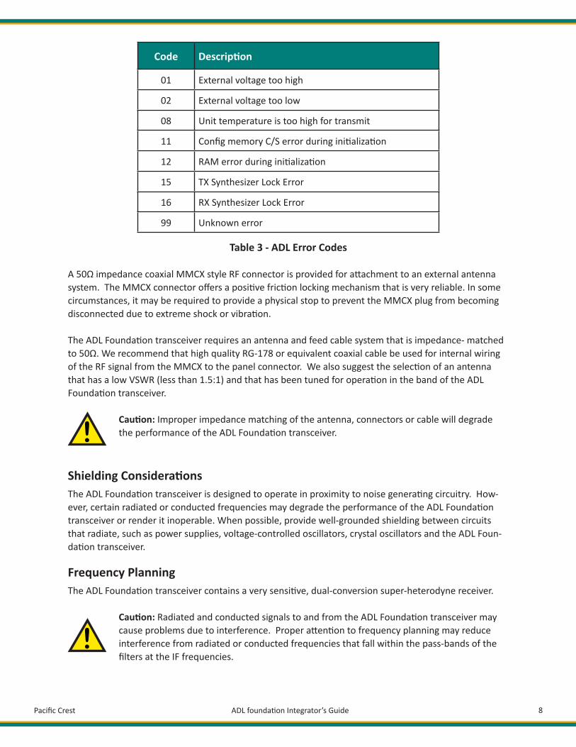
Error CodesThe ADL Founda on transceiver performs a variety of power-up and run- me tests to assure op mal op-era on. Tests include environmental as well as electrical measurements designed to avoid damage to the unit while maintaining adequate opera on. In the event of an error condi on, an error code is fl ashed on the ADL RXO’s LED lines, but only if they are connected to LED drivers. The number of mes the LED(s) fl ash equals the number of the error code. Table3 lists the possible error condi ons.
!
Pacifi c Crest ADL founda on Integrator’s Guide 8
Code Descrip on
01 External voltage too high
02 External voltage too low
08 Unit temperature is too high for transmit
11 Confi g memory C/S error during ini aliza on
12 RAM error during ini aliza on
15 TX Synthesizer Lock Error
16 RX Synthesizer Lock Error
99 Unknown error
Table 3 - ADL Error Codes
A 50Ω impedance coaxial MMCX style RF connector is provided for a achment to an external antenna system. The MMCX connector off ers a posi ve fric on locking mechanism that is very reliable. In some circumstances, it may be required to provide a physical stop to prevent the MMCX plug from becoming disconnected due to extreme shock or vibra on.
The ADL Founda on transceiver requires an antenna and feed cable system that is impedance- matched to 50Ω. We recommend that high quality RG-178 or equivalent coaxial cable be used for internal wiring of the RF signal from the MMCX to the panel connector. We also suggest the selec on of an antenna that has a low VSWR (less than 1.5:1) and that has been tuned for opera on in the band of the ADL Founda on transceiver.
Cau on: Improper impedance matching of the antenna, connectors or cable will degrade the performance of the ADL Founda on transceiver.
Shielding Considera ons The ADL Founda on transceiver is designed to operate in proximity to noise genera ng circuitry. How-ever, certain radiated or conducted frequencies may degrade the performance of the ADL Founda on transceiver or render it inoperable. When possible, provide well-grounded shielding between circuits that radiate, such as power supplies, voltage-controlled oscillators, crystal oscillators and the ADL Foun-da on transceiver.
Frequency Planning The ADL Founda on transceiver contains a very sensi ve, dual-conversion super-heterodyne receiver.
Cau on: Radiated and conducted signals to and from the ADL Founda on transceiver may cause problems due to interference. Proper a en on to frequency planning may reduce interference from radiated or conducted frequencies that fall within the pass-bands of the fi lters at the IF frequencies.
!
!

Pacifi c Crest ADL founda on Integrator’s Guide 9
We recommend the use of upfront analysis of the product frequency plan (including harmonics) and then the use of a spectrum analyzer to determine the poten al for interference within the pass-bands of the various front-end and band pass fi lters.
The following table indicates the frequencies and band pass fi lter characteris cs that are areas of poten- al interference.
Circuit Center Frequency (MHz) Bandwidth (MHz)
RF front-end 410 or 450(depending on model) 40
First IF 54.45 0.015
Second IF 0.450 0.010
Table 4 - ADL Founda on Frequency Plan
Mechanical Considera ons EMI interferers The ADL Founda on transceiver is easily mounted inside new and exis ng products. The ADL Founda on transceiver is specifi cally designed for opera on in harsh environments. For best performance, mount the radio away from poten al EMI radiators and route RF signals apart from digital signals.
Cau on: We do not recommend the bundling of the antenna interface cable with other sig-nal cables internal to your product.
Shock and Vibra onSensi ve radio transceivers, such as the ADL Founda on transceiver, are suscep ble to interference due to mechanical shock and vibra on. To reduce the poten al for electromechanical interference, a robust moun ng scheme must be used when being integrated into other systems. A thin damping pad between the moun ng surface and the ADL Founda on transceiver may be required. We recommend the use of damping pads made of PORON(R) or a similar material.
Thermal TransferThe ADL Founda on transceiver requires addi onal thermal heat dissipa on in order to supply maximum power out at elevated ambient temperatures and high duty cycles. The ADL Founda on transceiver has a thermal sensor and a fi rmware controlled limit switch. The ADLF will shut down when the PCB temper-ature reaches 85°C to prevent permanent damage to transmi er. The integrated heat sink is adequate for most bench top tes ng but when the ADL Founda on transceiver is integrated into other systems addi onal thermal heat sinking must be considered. The ADLF will produce approximately 6 Wa s of heat at full RF power out.
Refer to Appendix A for moun ng diagrams and specifi ca on.
!
Pacifi c Crest ADL founda on Integrator’s Guide 10
Materials The ADL Founda on transceiver is housed in a metal shield that is a conductor and is electrically con-nected to the ground and signal ground pins.
Service and Support Philosophy Pacifi c Crest is dedicated to providing the very best service and support possible. We recognize that the success of our business is directly related to the success our customers have in using our products. For this reason, we provide easy access with our toll free number, which we encourage our customers to use if they are experiencing diffi cul es or problems with the products we supply.
Let us know what you think. A cornerstone of our business philosophy is to evolve our product lines to match the needs of our customers. Your input allows us to be er determine what we need to do to keep our product and support off erings in alignment with your needs.
Phone/Internet Support Phone support is available during our business hours, Monday through Friday (7 a.m. to 4 p.m. Pacifi c Standard Time). Call 1-800-795-1001 (U.S. and Canada), +1-408-481-8070 (Interna onal), +1-408-481-8984 (Fax). You can contact the support group via our web site, www.Pacifi cCrest.com or send an e-mail to support@pacifi ccrest.com
Warranty One-Year Limited Warranty This warranty gives you specifi c legal rights. You may also have other rights which vary from state to state or province to province.
Pacifi c Crest warrants its ADL Founda on transceiver radio modem products against defects in materi-als and workmanship for a period of one year from receipt by the end user. During the warranty period, Pacifi c Crest will, at its op on, either repair or replace products that prove to be defec ve.
Exclusions Should Pacifi c Crest be unable to repair or replace the product within a reasonable amount of me, a refund of purchase price may be given upon return of the product. The warranty on your ADL Founda on transceiver radio modem shall not apply to defects resul ng from: • Improper or inadequate maintenance by the customer • Unauthorized modifi ca on or misuse • Opera on outside of the environmental specifi ca ons for the product • Negligence or misuse
Warranty Limita ons The warranty set forth above is exclusive and no other warranty, whether wri en or oral, is expressed or implied. Pacifi c Crest specifi cally disclaims the implied warran es of merchantability and fi tness for a par cular purpose.
Pacifi c Crest ADL founda on Integrator’s Guide 11
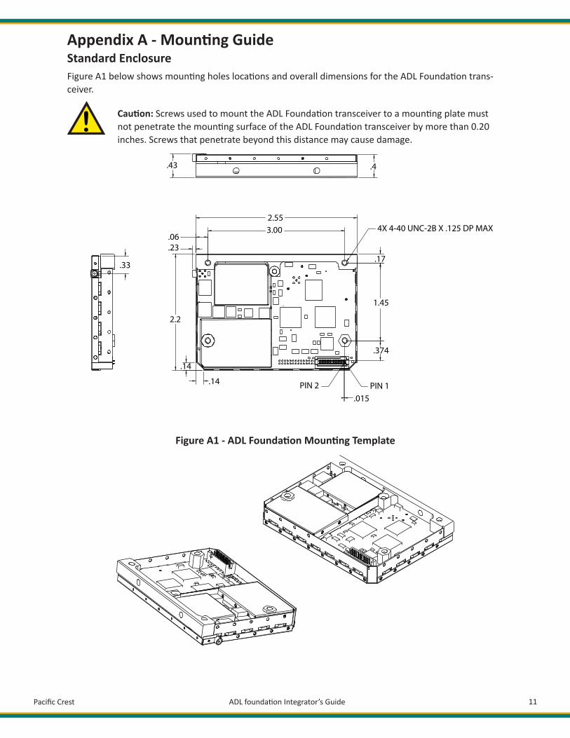
Appendix A - Moun ng Guide Standard Enclosure Figure A1 below shows moun ng holes loca ons and overall dimensions for the ADL Founda on trans-ceiver.
Cau on: Screws used to mount the ADL Founda on transceiver to a moun ng plate must not penetrate the moun ng surface of the ADL Founda on transceiver by more than 0.20 inches. Screws that penetrate beyond this distance may cause damage.
Figure A1 - ADL Founda on Moun ng Template
.33
.43
.06
.23
2.2
2.553.00 4X 4-40 UNC-2B X .125 DP MAX
.4
.17
1.45
.374
PIN 2 PIN 1.015
.14
.14
!

Pacifi c Crest ADL founda on Integrator’s Guide 12
Appendix B - Cables and Connectors Value-Added Cable Products Pacifi c Crest manufactures a wide variety of high-quality custom cables in support of its OEM customers. Contact your Pacifi c Crest sales representa ve to discuss your custom cable requirements.
Interface Connector The 20-pin data/power header is a Samtec TFM series housing a standard-confi gura on connector, Samtec part number TFM-110-11-S-D. The ma ng Samtec connector is part number SFM-110-01-S-D for a board-to-board interface that is coincident with the moun ng hardware and heat sink (.25” ma ng height). See Samtec website www.samtec.com for other ma ng connector op ons.
RF Connector The RF connector is compa ble with an MMCX-style coaxial plug. Plugs are available from many sources and in many confi gura ons. We use plugs manufactured by Radiall. Radiall MMCX right-angle plug for use with RG-178 cable is part number R110 172 100. Radiall MMCX straight plug for use with RG-178 cable is part number R110 083 120.
Appendix C - Technical Specifi ca ons General Interface DTE - DCE Interface RS-232 or CMOS, 115.2 kbps maximum
Power Requirements External 6.0 – 30.0 VDC, +/- 0.50 VDCDuring RX 0.6 Wa s nominal @ 7.4 VDCDuring TX 7 Wa s nominal @ 7.4 VDC, 1W RF output
Radio Specifi ca ons Frequency Bands390-430 MHz430-450 MHz
Frequency Control Synthesized 12.5 kHz tuning resolu onFrequency stability +/- 1PPM
Channel Spacing Channel spacing 12.5/25 kHz (user-selectable)
RF Transmi er Output0.1 – 1 Wa (Programmable)
Sensi vity-110 dBm BER = 1 x 10⁻⁵
Pacifi c Crest ADL founda on Integrator’s Guide 13
Adjacent Channel Selec vity >55dB
Type Cer fi ca onAll models are type accepted and cer fi ed for opera on in the U.S., Europe, Australia, New Zealand, and Canada FCC, IC, EU, NZ, Australia ETS300-113-2
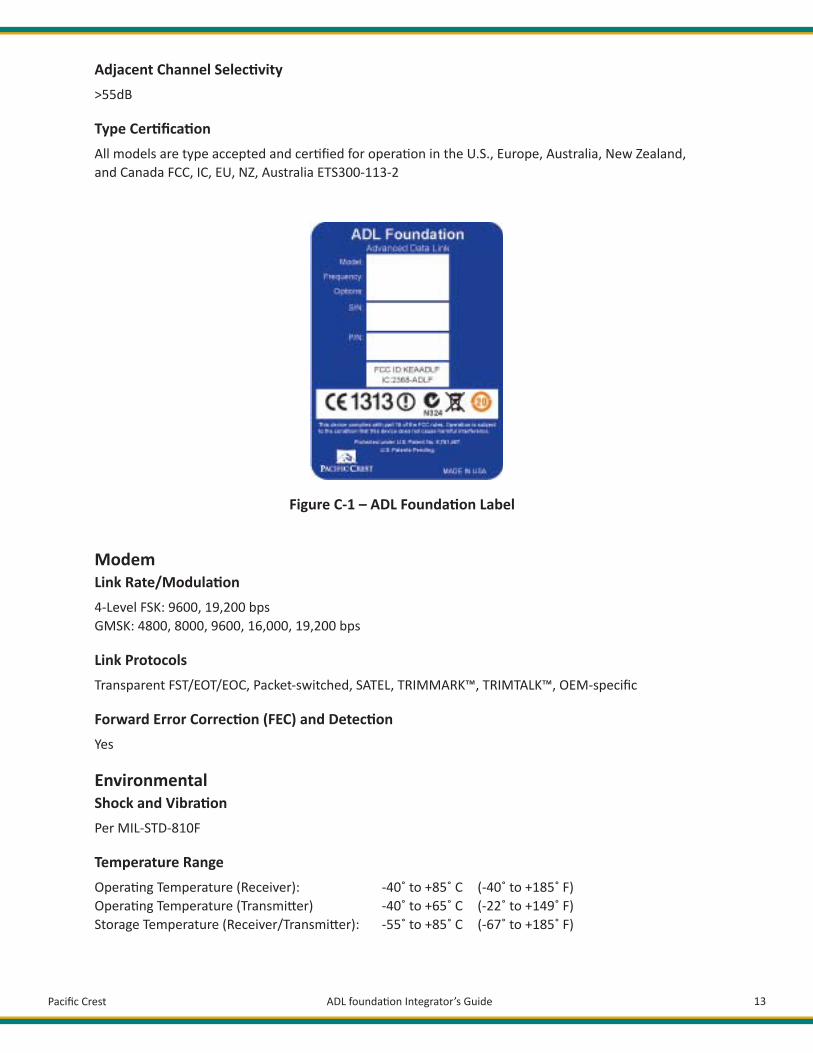
Figure C-1 – ADL Founda on Label
Modem Link Rate/Modula on 4-Level FSK: 9600, 19,200 bpsGMSK: 4800, 8000, 9600, 16,000, 19,200 bps
Link Protocols Transparent FST/EOT/EOC, Packet-switched, SATEL, TRIMMARK™, TRIMTALK™, OEM-specifi c
Forward Error Correc on (FEC) and Detec on Yes
EnvironmentalShock and Vibra on Per MIL-STD-810F
Temperature Range Opera ng Temperature (Receiver): -40˚ to +85˚ C (-40˚ to +185˚ F)Opera ng Temperature (Transmi er) -40˚ to +65˚ C (-22˚ to +149˚ F)Storage Temperature (Receiver/Transmi er): -55˚ to +85˚ C (-67˚ to +185˚ F)

Pacifi c Crest ADL founda on Integrator’s Guide 14
MechanicalDimensions7.6 cm W x 5.4 cm D x 1.1 cm H (3.0”W x 2.2”D x 0.4”H)
Weight 70 grams (2.5 oz.)Appendix D – API CommandsA descrip on of the ADL Founda on transceiver Applica on Programmer Interface is available to quali-fi ed Pacifi c Crest development partners. Please contact sales@Pacifi cCrest.com.
Appendix E – ADL TestDescrip onThe ADL Test applica on is used to perform func onal radio tests on Pacifi c Crest ADL radios.
UsageSet radio to command mode: Start applica on Select Serial Port + Data Rate to connect to radio Select So Break (Put radio into command mode, default behavior for ADL radio is that it is in data mode.)
Run Test Select Link Rate Select Modula on Select Channel Select Transmit Test Select Adjust Frequency Error

Pacifi c Crest ADL founda on Integrator’s Guide 15
Pacifi c Crest 510 DeGuigne Drive Sunnyvale, CA 94085