ADJUSTMENT OF AUTOMATIC COMPACTION DEVICES TO ACHIEVE ... · compaction devices to achieve uniform...
29
ADJUSTMENT OF AUTOMATIC COMPACTION DEVICES TO ACHIEVE UNIFORM RAMMER COVERAGE Decedaes 7984 Engineering and Research Center Department of the Interior * Bureau of Reclamation Division of Research and Laboratory Services Geotechnical Branch
Transcript of ADJUSTMENT OF AUTOMATIC COMPACTION DEVICES TO ACHIEVE ... · compaction devices to achieve uniform...
ADJUSTMENT OF AUTOMATIC COMPACTION DEVICES TO ACHIEVE UNIFORM RAMMER COVERAGE
D e c e d a e s 7984 Engineering and Research Center
Department of the Interior * Bureau of Reclamat ion Division of Research a n d
Laboratory Services
Geotechnica l Branch

Adjustment of Automatic Compaction Devices December 1984
to Achieve Uniform Rammer Coverage 6. PERFORMING O R G A N I Z A T I O N CODE
-- 7. A U T H O R ~ )
5 vaughan D. Goldsmith DeWayne A. CampbelCC
13. T Y P E O F R E P O R T A N D P E R I O D C O V E R E D
12. S P O N S O R I N G A G E N C Y N A M E A N D ADDRESS
8. P E R F O R M I N G O R G A N I Z A T I O N R E P O R T NO.
GR-84- 1 5 - 9. PERFORMING O R G A N I Z A T I O N N A M E A N D ADDRESS
Bureau of Reclamation Engineering and Research Center Denver, CO 80225
1 0 . WORK U N I T NO.
1 1 . C O N T R A C T OR G R A N T NO.
Microfiche and/or hard copy available at the Engineering and Research Center, Denver, Colorado.
Editor:REC(c)
Bureau of Reclamation Engineering and Research Center Denver, CO 80225
16. A B S T R A C T
1 4 . SPONSORING A G E N C Y CODE
DlBR
A study was performed to determine the proper rotational adjustment of automatic soil compaction devices. Compaction tests were performed to investigate the effects of varying the rotational adjustment. Adjustments that produced from 6.25 to 10.5 blows per revo- lution yielded acceptable results, with 8.33 blows per revolution the recommended value. Adjustment of the equipment to achieve 8.33 blows per revolution involves a relatively simple seven-step procedure.
15. S U P P L E M E N T A R Y N O T E S
a. DESCRIPTORS-- soil testing/ Proctor compaction/ "automatic compaction device/ "compaction equipment/ "compaction tests/ compaction
c. C O S A T I F ie ld /Group 08M COWRR: 0813 SR IM: 2 1 . NO. O F P A G E S
23 22. P R I C E
18. D l S T R l B U T l O N S T A T E M E N T 19. S E C U R I T Y C L A S S ( T H I S REPORT)
U N C L A S S I F I E D 2 0 . S E C U R I T Y C L A S S
( T H I S PAGE)
U N C L A S S I F I E D

ADJUSTMENT OF AUTOMATIC COMPACTION DEVICES TO ACHIEVE UNIFORM
RAMMER COVERAGE
Vaughan D. Goldsmith DeWayne A. Campbell
Geotechnical Branch Division of Research and Laboratory Services
Engineering and Research Center Denver, Colorado
December 1984
UNITED STATES DEPARTMENT OF THE INTERIOR * BUREAU OF RECLAMATION

As the Nation's principal conservation agency. the Department of theInterior has responsibility for most of our nationally owned publiclands and natural resources. This includes fostering the wisest use ofour land and water resources, protecting our fish and wildlife, preserv-ing the environmental and cultural values of our national parks andhistorical places, and providing for the enjoyment of life through out-door recreation. The Department assesses our energy and mineralresources and works to assure that their development is in the bestinterests of all our people. The Department also has a major respon-sibility for American Indian reservation communities and for peoplewho live in Island Territories under U.S. Administration.
The information contained in this report regarding commercial prod-ucts or firms may not be used for advertising or promotional purposesand is not to be construed as an endorsement of any product or firmby the Bureau of Reclamation.
The information contained in this report was developed for the Bureauof Reclamation; no warranty as to the accuracy. usefulness. or com-pleteness is expressed or implied.
ii

CONTENTS
Introduction .............
Terminology .............
Conclusions ............
Recommendations ..............
Equipment ..............
Previous recommendations from various sources...........................................................................
Testing program ........
Test results ..........
Equipment adjustment.................................................................................................................
Bibliography . .............
Appendix-Compaction test data sheets.........................................................................................
Table
Figure
TABLES
1
2
Test soils.......................................................................................................................
Maximum dry unit weight and optimum moisture content produced by various rammercoverage settings.......................................................................................................
FIGURES
1
2
3
4
5
Compaction curves for CL-ML soil...................................................................................
Compaction curves for CL soil.........................................................................................
Compaction curves for CH soil........................................................................................
Matchmark locations """"""""""""""""""""""""""""""'"
Spacer rod adjustment and detail....................................................................................
iii
Page
2
2
2
3
4
5
6
13
3
4
7
8
9
10
11


INTRODUCTION
Inquiries were received concerning the adjustment of automatic compaction devices to achieve
proper coverage by the rammer in the compaction mold. The devices used at the Engineering and
Research Center laboratory. have traditionally been set at 8 blows per revolution, but available
information on proper rotational adjustment was inconsistent. A study was made so that USBR
(Bureau of Reclamation) automatic compaction devices could be adjusted consistently and cor-
rectly.
TERMINOLOGY
The term "automatic compaction device" refers to a mechanical device used to perform the
laboratory (Proctor) compaction test by automatically applying blows from a 2.000-in (50.80-mm)
diameter, 5.50-lbm (2.49-kg) rammer to the soil in a 4.000-in (101.6-mm) diameter compaction
mold. One of two methods is used to obtain uniform coverage of the rammer on the surface of
each soil specimen. The first method uses a fixed rammer location with a compaction mold that
rotates either automatically or manually. The second method uses a fixed compaction mold with
a rammer that rotates automatically. In both methods, the rammer impacts the soil around the
periphery of the compaction mold. The automatic compaction device with the rotating rammer is
described in this report; nevertheless, the concepts in this report dealing with uniform coverage
apply to both types of devices.
In this report the phrase "blows per revolution" is used irrespective of the compaction method.
Therefore, an automatic compaction device adjusted to produce 8 blows per revolution delivers
8 equally spaced blows (45 degrees of rotation between adjacent blows) around the periphery of
the compaction mold in one 360-degree cycle for both types of device.
CONCLUSIONS
1. Automatic compaction device settings that result in approximately 6 to 10 blows per revolution
yield test results within the precision and accuracy limitations prescribed by ASTM (American
Society for Testing and Materials) for the laboratory compaction test.
2. A setting that yields 8.33 blows per revolution is relatively simple to obtain and results in an
even 25 blows in three revolutions while not impacting the same location twice.
RECOMMENDATION
Automatic compaction devices should be adjusted to obtain 8.33 blows per revolution as described
in this report.
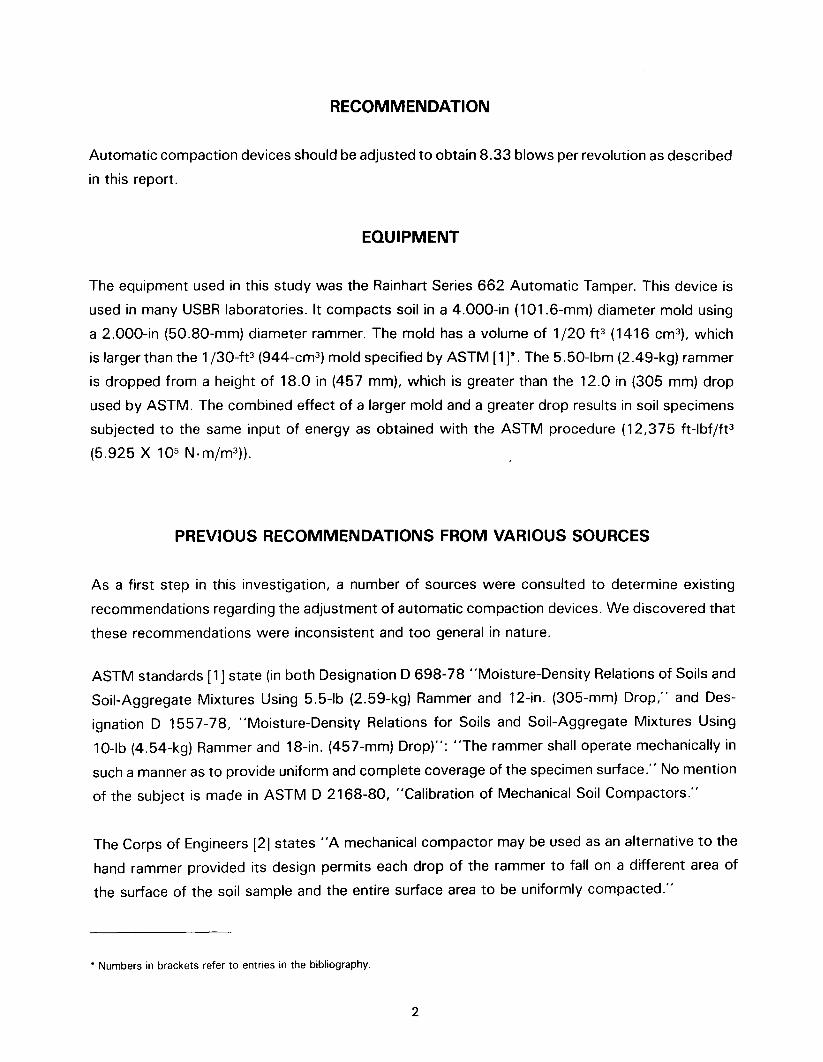
EQUIPMENT
The equipment used in this study was the Rainhart Series 662 Automatic Tamper. This device is
used in many USSR laboratories. It compacts soil in a 4.000-in (101.6-mm) diameter mold using
a 2.000-in (50.80-mm) diameter rammer. The mold has a volume of 1/20 ft3 (1416 cm3), which
is larger than the 1/30-ft3 (944-cm3) mold specified by ASTM [1]*. The 5. 50-Ibm (2 A9-kg) rammer
is dropped from a height of 18.0 in (457 mm), which is greater than the 12.0 in (305 mm) drop
used by ASTM. The combined effect of a larger mold and a greater drop results in soil specimens
subjected to the same input of energy as obtained with the ASTM procedure (12,375 ft-lbf/ft3
(5.925 X 10⁵ N.m/m3)).
PREVIOUS RECOMMENDATIONS FROM VARIOUS SOURCES
As a first step in this investigation, a number of sources were consulted to determine existing
recommendations regarding the adjustment of automatic compaction devices. We discovered that
these recommendations were inconsistent and too general in nature.
ASTM standards [1] state (in both Designation D 698-78 "Moisture-Density Relations of Soils and
Soil-Aggregate Mixtures Using 5.5-lb (2.59-kg) Rammer and 12-in. (305-mm) Drop," and Des-
ignation D 1557-78, "Moisture-Density Relations for Soils and Soil-Aggregate Mixtures Using
10-lb (4.54-kg) Rammer and 18-in. (457-mm) Drop)": "The rammer shall operate mechanically in
such a manner as to provide uniform and complete coverage of the specimen surface." No mention
of the subject is made in ASTM D 2168-80, "Calibration of Mechanical Soil Compactors."
The Corps of Engineers [2] states "A mechanical compactor may be used as an alternative to the
hand rammer provided its design permits each drop of the rammer to fall on a different area of
the surface of the soil sample and the entire surface area to be uniformly compacted."
.Numbers in brackets refer to entries in the bibliography.
2

Personnel with the Corps of Engineers' Waterways Experiment Station revealed that they typically
set their automatic compaction devices for eight blows per revolution, but had not studied the
adjustment of these devices.
The Operating and Service Manual for the Rainhart Series 662 Automatic Compactor [3] states
"Generally, if the blows overlap about 20 percent to 25 percent, the resulting densities will ap-
proximate those obtained using proper manual compaction." However, contacts with the Rainhart
Company indicated that their 20-to 25-percent overlap recommendation was based on a study
performed by the Texas Highway Department using a 6-in-diameter mold and a "pie-shaped"
rammer. Therefore, their recommendation is not directly applicable to the USSR procedure.
The USSR [4] recommends that' 'The blows shall be uniformly distributed over the surface of the
layer." A check of several automatic compaction devices used in USSR laboratories revealed that
the machines had been adjusted to deliver from 7 to 10 blows per revolution. The consensus was
that 8 blows per revolution was the most commonly used setting. However, a setting of 8 blows
per revolution does not strictly satisfy the requirement of "uniform coverage" because the rammer
strikes in the same location on successive revolutions. This leaves areas around the periphery of
the mold that are never directly impacted by the rammer.
TESTING PROGRAM
A limited testing program was planned to investigate three different soils and three different
compactor settings.
The three soils selected for testing exhibited a fairly wide range of characteristics to represent
varied field conditions. The characteristics of these soils are summarized in table 1.
Table 1. - Test soils.
Sample no.Laboratory classificationTypical nameLiquid limitPlasticity indexPercent sandPercent finesSpecific gravity
23J-2CL-MLSilty sand25
31090
2.66
24G-103CLSandy clay27153565
2.68
55T-90CHFat clay6846
595
2.70
The solution expected to achieve the best results was to adjust the automatic compaction devices
to deliver 8.33 blows per revolution. This setting has several advantages over other possible
3
Sample No. 23J-2 24G-103 55T-90
Maximum Optimum Maximum Optimum Maximum Optimumdry unit moisture dry unit moisture dry unit moisture
Blows per weight content weight content weight contentrevolution Ibf/ft3 % Ibf/ft3 % Ibf/ft3 %
6.25 113.9 11.6 120.1 12.1 89.9 28.68.33 113.9 11.6 120.0 12.0 89.2 28.9
10.5 113.4 11.7 118.9 12.2 89.0 29.3
Maximum range 0.4 0.9 1.0 1.7 1.0 2.4of two results,expressed aspercent ofmean value*
settings:
1. Three complete revolutions result in the required 25 blows. This permits simple adjustment
of the compaction device. This adjustment is described later in this report.
2. During each revolution, blow locations are offset from the location of the blow in the previous
revolution by Y3 diameter of the rammer. This results in the most uniform coverage possible for
25 blows in a three-rotation cycle.
3. A setting of 8.33 blows per revolution is not greatly different from the settings commonly
used in most laboratories.
In addition, a 6.25-blows per revolution setting was chosen because its deviation from 8.33 was
approximately equal to that of the 6.25 setting.
The compaction apparatus used in this study was visually inspected and found to be in proper
working order. The height of drop and weight of rammer were properly calibrated. The compactor
was "warmed up" for 5 min before each test series. The soils were prepared and tested in
accordance with Earth Manual Designation E-11 [4].
TEST RESULTS
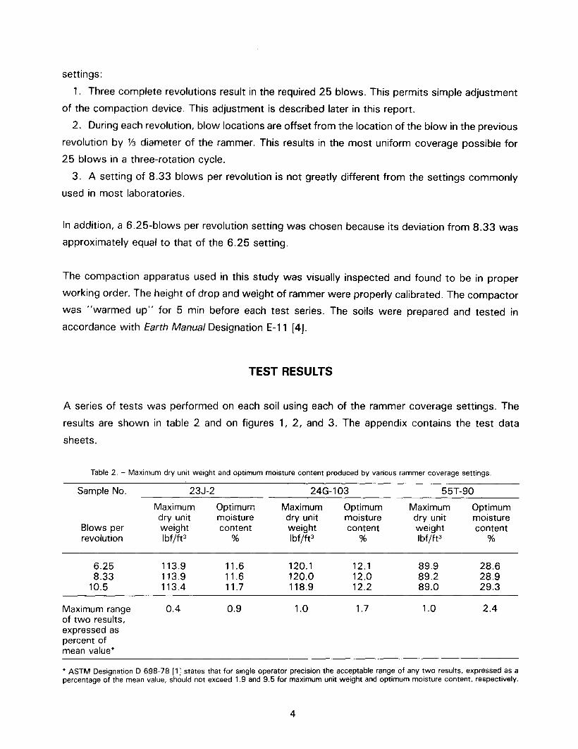
A series of tests was performed on each soil using each of the rammer coverage settings. The
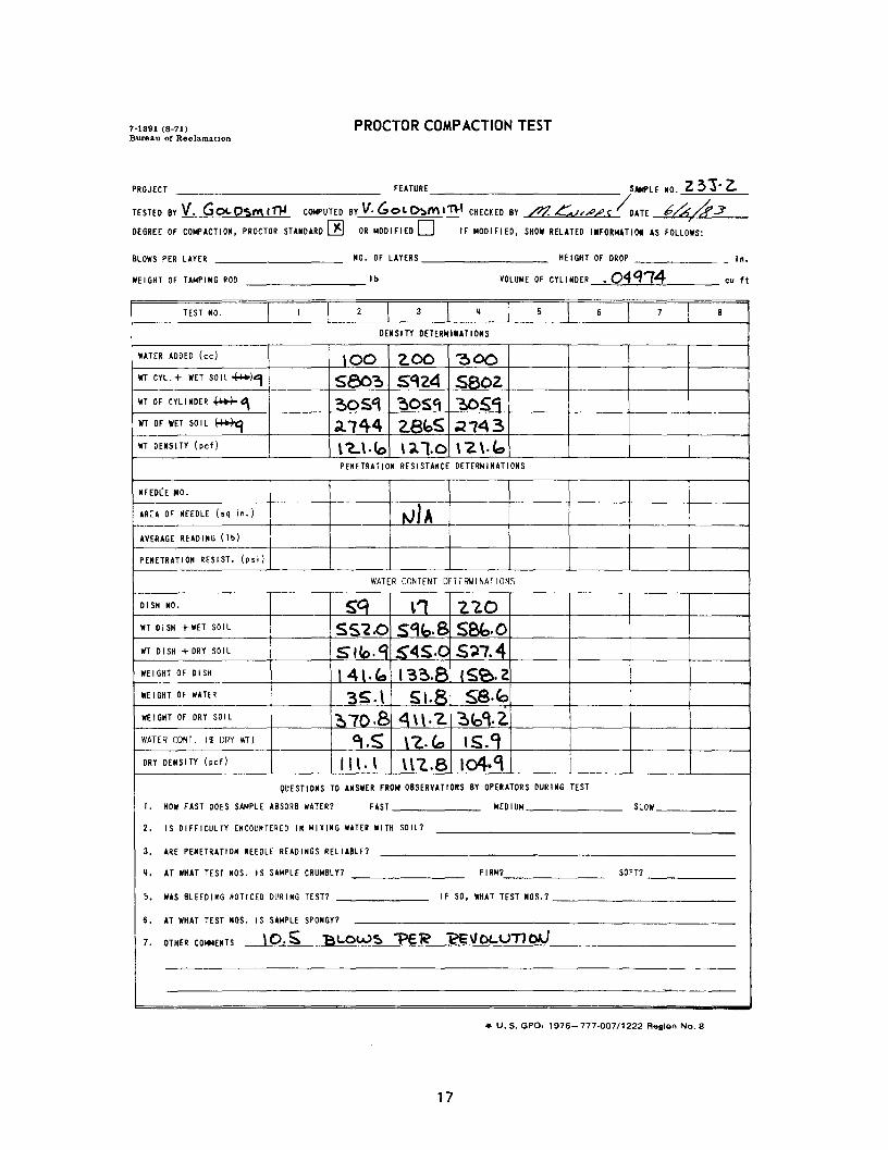
results are shown in table 2 and on figures 1, 2, and 3. The appendix contains the test data
sheets.
Table 2. - Maximum dry unit weight and optimum moisture content produced by various rammer coverage settings.
* ASTM Designation D 698-78 [1] states that for single operator precision the acceptable range of any two results, expressed as apercentage of the mean value, should not exceed 1.9 and 9.5 for maximum unit weight and optimum moisture content, respectively.
4

Although the data are limited, the values of maximum dry unit weight and optimum moisture
content for each soil are well within the limits of acceptable precision and accuracy described by
ASTMD 698-78 [1]. Altering the numberof blows per revolution (at least withinthe range between6.25 and 10.5) seems to have little affect on the measured compaction characteristics of soil.
Nevertheless, we recommended that automatic compaction devices be adjusted to provide ap-
proximately 8.33 blows per revolution because this adjustment is relatively simple to make, is
close to the settings already in use, and results in uniform coverage of the compaction specimen.
EQUIPMENT ADJUSTMENT
Adjustment of the Rainhart Series 662 Automatic Tamper to achieve 8.33 blows per revolution
is relatively simple. The procedure is described below.
1. Place a rag, soil, or similar soft material in the mold and operate the machine for a
few cycles. Always keep the switch in the "OFF" position while the machine is not in
operation.
2. Remove the collar assembly.
3. Place a matchmark on the top edge of the mold and on the top of the rammer head
(see fig. 4). Make sure these marks can be easily seen when the machine is not in
operation. This may be accomplished by inserting enough soil or other soft material into
the mold so that while the rammer is resting on the soft material, the top of the rammer
will be at approximately the same elevation as the top of the mold.
4. Match the marks on the mold and the rammer head and operate the machine through
one 25-blow cycle to check the rotation. At 8.33 blows per revolution and 25 blows
per cycle, the rammer head should make three complete revolutions, after which the
marks should again match, within a tolerance of :t 1 in (25 mm). See figure 4 for an
example of how to measure this tolerance.
5. Reset the marks to match and repeat the test. If the test is within tolerance on three
consecutive trials, the machine needs no adjustment. If the tolerance is not met, ad-
justment of the rotation is required.
6. The amount of overlapping of blows is controlled by the angle of the spacer rod (see
fig. 5), which establishes the amount of rotation. Adjustment of the bottom of the spacer
rod towards the column will increase the amount of overlap. Conversely, adjustment of
the bottom of the spacer rod away from the column will decrease the amount of overlap.
Some experimentation may be necessary to arrive at the correct adjustment. Loosen the
5

handnut at the bottom of the spacer rod and slide the rod towards or away from the
column as necessary.
7. Tighten the handnut and repeat the test. Repeat this procedure until recommended
tolerances are met.
The rotation of the rammer should be checked and reset, if necessary, each time the machine is
calibrated.
BIBLIOGRAPHY
[1] 1984 Annual Book of ASTM Standards, vol. 04.08, Soil and Rock; Building Stones, DesignationD 698-78, "Moisture-Density Relations of Soils and Soil-Aggregate Mixtures Using a 5.5-lb (2.59-kg)Rammer and 12-in. (305-mm) Drop", American Society for Testing and Materials, 1984.
[2] Engineering ManUal EM 1110-2-1906, Laboratory Soils Testing, Department of the Army, Office of theChief of Engineers, Washington, D.C., 1970.
[3] Rainhart, Operating and Service Manual, Automatic Tamper, Series 662, 3rd ed.
[4] Earth Manual, 2d ed., Bureau of Reclamation, U.S. Government Printing Office, Washington, D.C., 1974.
6

118
...,J
r() 116f-lL.
'- 114CLCD...J
I 112
f-I~ 110w3:f- 108
z:J
>-106
a:(:)
104
1028
~~~O
~/~
"'0/0
0'
LEGENDSample No. 23J-2 (CL-ML)
br-- --l:::. 6.25 Blows per revolution0 08.33 Blows per revolution0 010.5 Blows per '-evolution
9 10 II 12MOl STU R E
13 14 15 16 17CONTENT - PERCENT
Figure 1. - Compaction curves for CL-ML soil.
18 19

122
120
118It).....LL
'- 116a..m.....J1141
.....:L 112C>-
ex> W
~110.....-Z::J J08>-a:Q
106
104
'\
~~/V" -......~"\
."...- --- '"/'
""
/?./ 'c ~'"/
/ '"~~/
/'rJ " ~~O-<l/ "\..
/
~,
~...
"'0"'0\
\..:~\S'
.~~'" ~'"
~:'\ ~"LEG END ~"Sample No. 25G - 103 ( C L) '\ '\
\ "6-- --6 6.25 Blows per revolution~~0 0 8.33 Blows per revolution~0----0 10.5 Blows per revolution "~- ~...
1028 10 II 12 13 14 15 16 17 18
MOISTURE CONTENT - PERCE NT
9 19 20 21
Figure 2. - Compaction curves for CL soil.

92
CD
rr>
l-ll..
90a..CD..J
88I
l-I(!) 86
w~
84I-Z:::>
82~a::0
8022
LEGENDSample No. 55T-109 (CH)
6.25 Blows8.33 Blows10.25 Blows
23 35 3624 25 26 27 28 29 30 31 32MOISTUR E CONTE NT - PER CENT
33 34

II
EXAMPLE -I MEASUREMENT
MAXIMUMALLOWABLEDEVIATION INITIAL
MATCHMARKPOSITION
MAXIMUM ALLOWABLEDEVIATION
Figure 4. - Matchmark locations.
10

COLUMN
-LA- DECREASE OVERLAP
INCREASE OVERLAP
Figure 5. - Spacer rod adjustment and deta~l.


APPENDIXCompaction Test Data Sheets


TEST NO. I 2 3 ~5 6 7 B
OENSITY DETERNIUTIONS
WATER ADDED (ee) \00 ZOO 300WT CYL.+ WET SOIL H-e-1, 5827 S9~b 580'\WT OF CYLINDER ~C\ ~O'Sc; ~OS~ ~OSC8WT OF WETSOIL (~c; ~1bB 2811 ;t.1S0WT DENSITY (pet) \ 'Z.l.' 1~1.S' \'2.\.'\
PENETRATION RESISTANCE DETERMINATIONS
NEED(E"°.
AREA OF NHDLE (Sq in.) NIAAVERAGE READING (Ib)
PENETRATION RESIST. (psi)
WATER CONTENT DET[RMI NATIONS
DISH NO. 30 ;t.~ C\(,WT DiSH + WETsoI L £01'\.0 G,:t \.S S09.0WT DISH +DRY SOIL Sil.1 S10.S 488. Z.WEIGHT OF DISH \ S 3. iD IbQ.q 151.2WEI GHT OF WATER 4\.~ S1.0 .<0.8WEI GHT OF DRY SOI L A 2.4. \ 400. '= ~~\.CWATER COOT. (% DRY WT) ~.1 1-<.1 IS.3DRY DENSITY (pet) 11\.'1 \\3.\ los.1
QUESTIONS TO ANSWERFROM OBSERVATIONS BY DPERATORS DURING TEST
I. HOW FAST DOES SAMPLE ABSORB WATER? FAST MEDI UM SLOW
2. IS DIFFICULTY ENCOUNTEREDIN MIXING WATERWITH SOIL?
3. ARE PENETRATION NEEDLE READINGS RELIABLE?
~. AT WHAT TEST NDS. IS SAMPLE CRUMBLY? FIRM? SOFT?
5. WAS BLEEDING NOTICED DeRING TEST? I F SO, WHAT TEST NO~.?
6. AT WHAT TEST NOS. I S SAMPLE SPONGY?
7. OTHER COMMENTS <0. 2 S" 'B1...OW5.. t>EJ? JZE Vo lUrtoN
'-.--- ---
--.. -.-.-_.
-
7-1891 (8-71)Bureau of Reclamation
PROCTOR COMP ACTION TEST
PROJECT FEATURE SAMPLE NO. Z. ~ j - z..TESTED BY V. <:'O'-O~f'I\l11-4 COMPUTEDBYV. GOLOSltllrH CHECKED BY /17. KAJI/'1'5 / DATE ~/b/,r'3DEGREE OF COMPACTION. PROCTOR STANDARD [1J OR MODIFIED 0 IF MODIFIED, SHOW RELATED InORMATIOI AS FOLLOWS:
BLOWS PER LAYER NO. OF LAYERS HE I GHT OF DROP- in.
WEIGHT OF TAMPING ROD I b VOLUME OF CYlI NDER .oqQ14 eu ft
.u. S. GPO. 1976-777-007/1222 Region No.8
15

TEST NO, I 2 3 ~5 6 7 B
DENSITY DETERI4IUTlONS
WATER ADDED (cc) \00 ZOO ~OOWT CYl.+ WET SOIL ~Se\b SCf:.b S844WT OF CYlI NDER ~C\ ~05'\ ~OS~ ~oS'tWT OF WET SOI L
'""*"1 ~iS1 ;t811 :2.18'5:WT DENSITY (pet) \ ':t~.~ tAl.S \2~.4
PE~~TRATION RESISTANCE DETERMINATIONS
NEEDLE"°.
AREA OF HEEDLE (sq in.) foliA
AVERAGE READING (I b)
PENETRATIO~ RESIST. (psi)
WATER CONTENT DEHRMI NATIONS
DISH NO. \53 \&\ L\4WT DiSH + WETso I L SSlD.8 SC\ 3.0 4~.OWT DISH +DRY SOIL 5.,'2.3 SO\. '2. 4~1.ZWEIGHT OF DISH \~\.O 1 ~'5..~ \'2b ,WEIGHT OF WATER ~4.S 4\.B 4S.BWEIGHT OF DRY SOIL 3cDI.3 ~~~.q3rt. 1
WATER CONT. I% DRY WT) q.S \2.4 \S.?DRY DENSITY (pet) t\\.~ \ \~.4 \~'1
QUESTIONS TO ANSWERFROM OBSERVATIONS BY OPERATORSDURING TEST
I. HOW FAST DOES SAMPLE '""ORR WATER? FAST MEDI UM SLOW
2. IS ~IFFICULTY E,""eNTERED IN MIXI~G WATERWITH SOIL?
3. ARE PENETRATI O~ NEEDLE READI HGS REL I ABLE?
~. AT WHAT TEST NOS. IS SAMPLE CRUMBLY? FIRM? SOFT?
5. WAS BLEEDING ~OTICEDDVRI~G TEST? IF SO, WHAT TEST NOS.?
6. AT WHAT TEST NOS. I S SAMPLE SPONGY?
7. OTHER COMMENTS 8.~~ BL.O~.5 flEe t2€\lOl.U T10IJ
------ - -.---
7-1391 (8-71)Bureau of Reclamation
PROCTOR COMP ACTION TEST
PROJECT FEATURE SAMPLE N.O. 231- LTESTED BY V. GO'-O~I1)i COI4PUTEDBYV, Gell..I)ca.~11).ICHECKED BY /J1. K-v"""s /Dm ~/~4'3DEGREE OF COMPACT I ON, PROCTOR STANDARD ~ OR MODI F I EO 0 I F MOD I F I ED, SHOW RELATED IUORMATIOI AS FOLLOWS:
BLOWS PER LAYER NO. OF LAYERS HE I GHT OF DROP - in.
WEIGHT OF TAMPING ROO 1 b VOLUME OF CYLI NDER .04'174 cu ft
. u. S. GPO. 1976-777.007/1222 Region No.8
16
TEST NO. I 2 3 ij 5 6 7 B
DENSITY DETERIIIUTIONS
WATER ADDED (cc) \00 '2.00 ~OCWT CYL. + WET SOI L ++-PJ4 5803 St124 SBOZ.WT OF CYLINDER ~~~OS'1 ~OSCc ~SqWT OF WET SOIL ~;t1442.8loS ~143WT DENSITY (pcf) l c..\.(o \ ;?l.o \ '2 \. b
PENETRATION RESISTANCE DETERMINATIONS
NEEDCE 110.
ARa OF NEEDLE (sq in.) ~IAAVERAGE READI NG (I b)
PENETRATION RESIST. (psi)
WATER CONTENT DET[1i\41 NAT IONS
0 I SH NO. Sq \1 "2.7.0WT 0 i SH + WETso I L 55'2.0 S'Ib.8 S8b.OWT DISH +DRY SOIL SI(o.q S'4S.C S~?4WEIGHT OF DISH 14\.~ 13~.8 (S~.2WEI GHT OF WATER 3S.\ 51.8 SS.~WEIGHT OF DRY SOIL ~?D.8 4\\.'2. :?>b~. 2.WATER CONT. lei:DRY WT) C!t.S \~.Co \5.9DRY DENSITY (pcf) 1\ \. \ \l '2..8 104. '\
QUESTIONS TO ANSWER FRON OBSERVATIONS BY OPERATORSDURING TEST
I. HOW FAST DOES SAMPLE ABSORB WATER? FAST MED I UM SLOW
2. IS DIFFICULTY ENCOUNTERED IN MIXING WATER WITH SOIL?
3. ARE PENETRATION NEEDLE READINGS RELIABLE?
~. AT WHAT TEST NOS. IS SAMPLE CRUMBLY? FIRM? SOFT?
5. WAS BLEEDING NOTICED DURING TEST? IF SO, WHAT TEST NOS.?
6. AT WHAT TEST NOS. I S SAMPLE SPONGY?
7. OTHER COMMENTS \O.S 'Bl..Ov.>5 1>E'R 1?E'IJOc..uTJ OJJ
---
7-1891 (8-71)Bureau of Reclamation
PROCTOR COMP ACTION TEST
PROJECT FEATURE SANPLE NO. Z 3 j -Z.
TESTEDBYV. Goc.Oc:.tW\I1}4 COI4PUTEDByV.Goc..D~ml1\-1 CHECKED BY /??C v""""""'/DATE 64,&3DEGREE OF COMPACTION, PROCTOR STANDARD~ OR MODIFI ED D 1F MODI F I ED, SHOWRELATED I nORMAT I 01 AS FOLLOWS:
BLOWS PER LAYER NO. OF LAYERS HEIGHT OF DROP
VOLUME OF en I NDER .04 Q'"74- in.
WEIGHT OF TAMPING ROD Ib cu ft
4' U. S. GPO. 1976-777-007/1222 Region No. S
17

TEST NO. I 2 3 * 5 6 7 8
DENSITY DETERMINATIONS
WATER ADDED (ee) ~oo 400 SOO ~OOWI CYL.+ WETso I L tttr1 ~S~b1 ~oq~ ~O325QOOWT OF CYLI NDER ~., 130S'i "?:IOS't '30SCf '30S'C}
WI OFWETSOIL~., .:2.808 ~0.34 ~~13 ..184 \WT DENSITY (pet) ~\~.S' I~\.B l2S.QI \2.8.~
PENETRATION RESISTANCE DETERMINATIONS
NEEDLE 140.
AREA OF NEEDLE (Sq in.) tV,~AVERAGEREADING (Ib)
PENETRATION RESIST. (psi)
WATER CONTENT DETERMI NAT IONS
DISH NO. S:O LI4 220 sqWT DiSH +WET SOIL SIQ.fo ~aa.bS8Z.B S81,7WT DISH +ORY SOIL 148Ct.O ..<"~\.~ 1£"24.0 514.0WEI GHT OF DISH \10.8 I 2~. \ \ SB. 2.. 14b"WEI GHT OF WATER 3D.b Sf.O S8.8 73.1WEIGHT OF DRY SOIL 318.2 40$,S 3bS.& ~"1. 'iWATER CaNT. (% DRY WT) ~.(." \4. \ \b. \ 20.0DRY DENSITY (pet) \\l.b \ \ 1. '\ \ l '3. S \04. '\
QUESTIONS TO ANSWERFROM OBSERVATIONS BY OPERATORSDURING TEST
I. HOW FAST DOES SAMPLE ABSORB WATER? FAST MEDI UM SLOW
2. IS DIFFICULTY ENCOUNTEREDIN MIXING WATERWITH SOIL?
3. ARE PENETRATION NEEDLE READI NGS REL I ABLE?
*. AT WHAT TEST NOS. IS SAMPLE CRUMBLY7 FIRM? SOFT?
5. WAS BLEEDING NOTICED DURING TEST? I F SO, WHAT TEST NOS.?
6. AT WHAT TEST NOS. I S SAMPLE SPONGY?
7. OTHER COMMENTS 6.lS 8LOtU5 'PEe ecVOL()T1oAl
->
7-1891 (8-71)Bureau or Reclamation
PROCTOR COMP ACTION TEST
PROJECT FEATURE/LE NO. ZQ6 -10.3
TESTEO BY V. Go,- O~M'~ C~PUTEDBY\(. GO~I>!oMI~ CHECKED By ~ L'A) ,/-,,P5 DATE ~A h3DEGREE OF COMPACTION, PROCTOR STANOARD 00 OR MODIFIED 0 IF MODIFIED, SHOW RELATED INFOMMATIOI AS FOLLOW~:
BLOWS PER LAYER NO. OF LAYERS HEIGHT OF DROP-
in.
WEIGHT OF TAMPING ROO I b VOLUME OF CYLI NDER . D4 q f 4 cu ft
. u. S. GPO. 1976-777-007/1222 Region NO.8
18

TEST NO. I 2 3 ~5 6 7 B
DENSITY DETERNINATIONS
WATER ADDED (ee) 300 400 SOO G::tooWI CYL.+ WETSOIL 440+~ S'443 ~qt.OO4 SMIWT OF CYLINDER ~~305<:1 305'4 ~t\sq .3OS'iWI OF WET SOIL ~28eA 3040 .2'14S" 2.83'2WT DENSITY (pcf) 12.1.8 134.7 \~.~ 12 S.5
PENETRATION RESISTANCE DETERMINATIONS
NEEDLE"°.
AREA OF NEEDLE (Sq in.) N YAAVERAGE READING (Ib)
PENETRATION RESIST. (psi)
WATER CONTENT DETEIi'MI NATIONS
DISH NO. \S~ \. \S~ '110WT DiSH + WETSOIl SB\.t.:, SQ1.\ (001.4 ~Iq.sWT DISH + DRY SOIL S"44. ~S4o." ~~.4<'44.CWEIGHT OF DISH 1 CoO. 't 13~.8 \bO.B \S?IWEI GHT OF WATER ~i.O Sea..s: b3.0 15.$WEI GHT OF DRY SOI L ~83.1 4Ob.~ 311.~ 3~.CjWATER CONT. (% DRY WT) q.b \~.9 l~.' \ q.5'DRY DENSITY (pcf) \ \b.~ \\S.3 111.8 l OS' .c
QUESTIONS TO ANSWER FROM OBSERVATIONS BY OPERATORSDURING TEST
,. HOW FAST DOES SAMPLE ABSORB WATER? FAST NEDI UM SLOW
2. IS DIFFICULTY ENCOUNTEREDIN MIXING WATERWITH SOIL?
3. ARE PENETRATION NEEDLE READINGS RELIABLE?
~. AT WHAT TEST NOS. I S SAMPLE CRUMBLY7 FIRM? SOFT?
5. WAS BLEEDING NOTICED DVRING TEST? IF SO. WHAT TEST NO~.?
6. AT WHAT TEST NOS. I S SAMPLE SPONGY?
7. OTHER COIol4ENTS 8.3~ 'BLOll.1S. PE2 ee voc.lJTI ON
- - ~--
7-1891 (8-71)Bureau of Reclamation
PROCTOR COMPACTION TEST
PROJECT FEATURE )ANPLE NO. z..46-/03
TESTED BY V. GO~OS~lfW COMPUTED BY \/. Go los"unl CHECKEDBY ~ -<;""/,,o/"'5 DATE (; A h3DEGREE OF COMPACTION. PROCTOR STANDARD ~ OR MODIFIED D IF MODIFIED, SHOW RELATED INFORMATIOI AS FOLLOWS:
BLOWS PER LAYER NO. OF LAYERS HE I GHT OF DROP - in.
WEIGHT OF TAMPING ROD I b VOLUME OF CYLI NDER .04Q14 eu ft
. u. S. GPO. 1976-777-007/1222 Region No.8
19

TEST NO. I 2 3 ij 5 5 7 8
DENSI TY DETERNIUTIONS
WATER ADDEO (ee) ~oo 400 .sm 1000WT CYL.+ WETso IL #e+<::j SGfZB ~Clb <0000 S8~3WT OF CYLI NDER ~~~SCj~Sq ~OSC1 ~csCtWT OF WET SO I L +++I-~ 2~'1 3011 2~4\ Z85~WT DENSITY (pef) 1~1.Z \~3.1 \3 0.4 \"2S."
PENETRATION RESISTANCE DETERMINATIONS
NEEDLE 140.
AREA OF NEEDLE (sQ in.) N 'AAVERAGE READING (Ib)
PENETRATION RESIST. (psi)
WATER CONTENT OETERMINATIONS
DISH NO. 30 "20'2. \8 \ '3 \WT DiSH + WETso I L to \C. '2. Co~l. \ ~4\.' fo4C.3 I
WT DISH +DRY SOIL ~foq.l seo.Z 51:>.1 Slo\.OWEI GHT 0 F DISH \S~.; 110.4 \ Co~.5 15'3.8WEI GHT OF WATER 40.S= ~Gs.q (07.4 7Q.3WEIGHT OF DRY SOIL 4\4.0 4C9.8 408.2 401.'2.WATER CONT. (% DRY WI) qB \~.Cf \fe.S; \q.S"DRYDENSITY (ref) \lS.8 \\1.4 \ I \.9 \OS. \
QUESTIONS TO ANSWERFROM OBSERVATIONS BY OPERATORSDURING TEST
I. HOW FAST DOES SAMPLE ABSORB WATER? FAST MEDI UM SLOW
2. IS DIFFICULTY ENCOUNTEREDIN MIXING WATERWITH SOIL?
3. ARE PENETRATI ON NEEDLE READI NGS REL I ABLE?
ij. AT WHAT TEST NOS. IS SAMPLE CRUMBLY? FIRM? SOFT?
5. WAS BLEEDING NOTICED DURING TEST? I F SO. WHAT TEST NOS.?
6. AT WHAT TEST NOS. IS SAIofPLE SPONGY?
7. OTHER COMMENTS 1Q.S; ~LOWs..?E. e eeVOL\.rrrON
7-1891 (8-71)Bureau of Reclamation
PROCTOR COMP ACTION TEST
PROJECT FEATURE7LE
NO. ~ G -, 03TESTED BY V. Go~O~,.r}l COI4PUTED BY y. 60L~mJ1H CHECKED BY ~ ~ DATE 1[4,/t':sDEGREE OF COMPACTION. PROCTOR STANDARD ~ OR MODIFIED 0 IF MODIFIED, SHOW RELATED IWFORMATIOI AS FOLLOWS:
BLOWS PER LAYER NO. OF LAYERS HE I GHT OF DROP - in.
WEIGHT OF TAMPING ROD Ib VOLUME OF cn I NOER .04Q14 eu ft
4' U. S. GPO. 1976-777.007/1222 Region No.8
20

TEST NO. I 2 3 ~5 6 7 B
DENSITY DETERMINATIONS
WATER ADDED (cc) bOO 700 ~qOOWT CYL.+ WETso I L-48-11 S t;:03 Slo4 ~S~SS S~IAWT OF CYLINDER ~'\ 1.,.__- ~Sq ~SCf3.0SqWT OF WET SOIL~, ~444 ;t SBi ;tS~" ~SS,WT DENSITY (pcf) \08.3 "4.1 , 'S.I "3.4
PENETRATION RESISTANCE DETERNINATIONS
NEED(E"0.
AREA OF NEEDLE (Sq in.) N AAVERAGE READING (Ib)
PENETRATION RESIST. (psi)
WATER CONTENT DETERMINAT IONS
DISH NO. 2.03 q~ '8' 50WT 0 iSH + WETso I L S~S., 5'12.8 S~~.O Sact. '1WT DISH +DRY SOIL ~l..A. ~4Q,.B 4 lot... '2. 48 '.S>WEI GHT 0 F 0 I SH , C.3. '1 \S1.' \Co~.S 170.~WEI GHT OF WATER 1~.~ QS.o q,.~ 1M IWEI GHT OF DRY SOIl ~\ ~~o.1 3£x).7 3\\.3WATERCONT. (% DRY WT) .2.4.b ~1.q ~:).J ~.q.1DRY DENSITY (pcf) &o.~ 8q.' 8'1.' 84.,
QUESTIONS TO ANSWERFROM OBSERVATIONS BY OPERATORSDURING TEST
I. HOW FAST DOES SANPLE ABSORB WATER? FAST !olEOI U!oI SLOW
2. IS DIFFICULTY ENCOUNTEREDIN MIXING WATER WITH SOIL?
3. ARE PENETRATION NEEDLE READI NGS RELI ABLE?
~. AT WHAT TEST NOS. IS SANPLE CRUNBLY? F fRN? SOFT?
5. WAS BLEEDING NOTICED DURING TEST? I F SO, WHAT TEST NOS.?
6. AT WHAT TEST NOS. I S SAMPLE SPONGY?
7. OTHER COMMENTS ~.z.~ 'B(..ows.1 f2E'JOLUnoAJ
-'- .;--
7-1891 (8-71)Bureau of ReclAmation
PROCTOR COMPACTION TEST
PROJECT FEATURE SAMPLE NO. SST -ql}TESTED BY V.G O&.O~M''R-' COMPUTED BY V. GO,-OSMtfft CHECKEDBY ,/1';, J::;J I ,..,.,...s~ATE~~/g' JDEGREE OF COMPACTION, PROCTOR STANDARD I1:J OR NODIFIED D IF NODI FlED, SHOW RELATED IWFORNATIOI AS FOLLOWS:
BLOWS PER LAYER NO. OF LAYERS HE I GHT OF DROP
VOLUNE OF CYliNDER .OL/qlt.{- in.
WEI GHT OF TANP I"G ROD Ib cu ft
. U.S.GPO.1976-777.007/1222 Region No.8
21

..
Mission of the Bureau of Reclamation
The Bureau o f Reclamation of the U.S. Department o f the Interior is responsible for the development and conservation of the Nation's water resources in the Western United States.
The Bureau S original purpose "to pror ~ a e for the reclamation o f arid and semiarid lands in the West" today covers a wide range of interre- lated functions. These include providing municipal and industrial water supplies; hydroelectric power generation; irrigation water for agricul- ture; water quality improvement; flood control; river navigation; river regulation and control; fish and wildlife enhancement; outdoor recrea- tion; and research on water-related design, construction, materials, atmospheric management, and wind and solar power.
Bureau programs most frequently are the result of close cooperation with the U.S. Congress, other Federal agencies, States, local govern- ments, academic institutions, water-user organizations, and other concerned groups.
A free pamphlet is available from the Bureau entitled "Publications for Sale." It describes some of the technical publications currently available, their cost, and how to order them. The pamphlet can be obtained upon request from the Bureau of Reclamation, Attn D-922, P 0 Box 25007, Denver Federal Center, Denver CO 80225-0007.