
Adjustment Item Menu Guide: TCRUrfg-esource.ricoh-usa.com/.../rfg034042~2.pdf · 2008-11-03 ·...
111
Adjustment Item Menu Guide: TCRU Model Name: Pro C900 Read this manual carefully before using this machine and keep it handy for future reference. 1
Transcript of Adjustment Item Menu Guide: TCRUrfg-esource.ricoh-usa.com/.../rfg034042~2.pdf · 2008-11-03 ·...

Adjustment Item Menu Guide: TCRU
Model Name:
Pro C900
Read this manual carefully before using this machine and keep it handy for future reference.
1
Introduction This manual contains detailed instructions and notes on the operation and use of this machine. For your safety and benefit, read this manual carefully before using the machine. Keep this manual in a handy place for quick reference.
Important • Contents of this manual are subject to change without prior notice. In no event
will the company be liable for direct, indirect, special, incidental, or consequential damages as a result of handling or operating the machine.
Notes: • Some illustrations in this manual might be slightly different from the machine. • Certain options might not be available in some countries. For details, please
contact your local dealer. • Depending on which country you are in, your machine may include certain
options as standard. For details, please contact your local dealer.
2

TABLE OF CONTENTS IMPORTANT NOTICE..................................................................................................... 4
1. Opening the [Adjustment] Menu ...................................................5
2. Display/Items and Features ...........................................................6
3. Values for Settings on the [Adjustment] Menu ............................8 3.1 [Adjustment] List........................................................................................................ 8 3.2 Adjustment Settings ................................................................................................ 11
4. Using the [Adjustment Settings for Skilled Operators] Menu ..28 4.1 Preparation: Displaying the [Adjustment Settings for Skilled Operators] menu ...... 28 4.2 Change the [Adjustment Settings for Skilled Operators] Mode............................... 31 4.3 Values for Settings on the [Adjustment Settings for Skilled Operators] Menu ........ 33
3

IMPORTANT NOTICE
IMPORTANT NOTICE SAFETY INFORMATION RWARNING 1. Do not open or remove the exterior covers while the main switch is turned on. 2. To avoid injury, never touch moving or high voltage components. 3. Keep hands away from internal components.
Mechanisms inside the machine can activate automatically, causing injury to hands. For example: when the machine’s main switch is turned to on and the fusing unit’s temperature falls below that of the machine, the warm-up mechanism will start automatically.
SYMBOLS This manual uses the following symbols:
RWARNING Indicates a potentially hazardous situation which, if instructions are not followed, could result in death or serious injury.
RCAUTION Indicates a potentially hazardous situation which, if instructions are not followed, may result in minor or moderate injury or damage to property.
Important: Indicates points to pay attention to when using the machine, and explanations of likely causes of paper misfeeds, damage to originals, or loss of data. Be sure to read these explanations.
Note: Indicates supplementary explanations of the machine’s functions, and instructions on resolving user errors. [ ]: indicates the names of keys that appear on the machine’s display panel. [ ] key: indicates the names of keys on the machine’s control panel.
4

1. Opening the [Adjustment] Menu
1. Opening the [Adjustment] Menu Important Before opening the [Adjustment] menu, turn the machine’s main power switch to OFF. For details about turning the power off, see "Turning On/Off the Power", About This Machine.
1. 2. 3.
4.
Insert the TCRU SD card into a free SD card slot on the back of the machine. Turn the main power switch to ON, and wait for the machine to warm up. After the machine has warmed up, press the [fierydriven] key on the control panel to display the Main Menu. On the Main Menu, press [Adjustment]. The [Adjustment] menu appears.
Note: • Pressing the [fierydriven] key causes the control panel to switch between the
[Adjustment] menu and the printer function screen. • After you finish using the [Adjustment] menu, remove the SD card from the card
slot. You do not need to switch the machine off to do this.
5

2. Display/Items and Features
2. Display/Items and Features
SUP013S 1. Items of Settings
Adjustment Settings are displayed in order.
SUP008S 2. [Open All], [Close All]
Open or close all Adjustment Settings categories at the same time. 3. Sorting
Types of Adjustment Settings can be scrolled or searched through by [Page] or [Line].
4. [Finished] Exit the [Adjustment] menu.
5. Adjustment Table Enter numbers or select items using the [./*], [1-0], and [#] keys.
6. [System Status] View the status of the machine.
6

2. Display/Items and Features
2.1.1 Inputting
To enter numbers or select items, use the machine’s [./*], [1-0], and [#] keys.
7

3. Values for Settings on the [Adjustment] Menu
3. Values for Settings on the [Adjustment] Menu 3.1 [Adjustment] List
Note: Items are displayed according to the direction of paper feed, which you can specify by pressing [Moving Direction = Horizontal (right and left)] and [Crossing Direction = Vertical (top and bottom)].
u Shift Image Adjustment
SP Item Description Reference
1-710 Leading Edge Registration1 3.2.1Adjust the horizontal position of the image
1-711 Leading Edge Registration2 (+ rightward; − leftward).
1-720 Side-to-Side Registration1 Adjust the vertical position of the image (+ upward; − downward). 1-721 Side-to-Side Registration2
8

3. Values for Settings on the [Adjustment] Menu
u Finishing Position Adjustments SP Item Description Reference
6-700 Staple Pos. Adj. Adjust the vertical position of the staples.
3.2.2
6-705 Punch Pos. Adj. (V) Adjust the horizontal position of the punch holes. Specify this setting for all types of punches. (The vertical position is determined based on the center of the paper.)
6-730 Fine Adjust Booklet Adjust Across
Adjust the horizontal position of the booklet staples.
6-735 Fold Pos. Adj. Adjust the horizontal position of the booklet fold.
6-755 Z Fold Pos. Fine Adj (End) Adjust the width of z-fold’s under fold. Specify this setting for all sizes of paper that can be z-folded.
6-760 Z Fold Pos. Fine Adj (Frm) Adjust the width of the z-fold. Specify this setting for all sizes of paper that can be z-folded.
6-780 Cover Center Pos. Adj. Adjust the horizontal alignment of the front page.
6-781 Cover Regist. Pos. Adj. Adjust the vertical alignment of the front page.
6-782 Rect. Angle Adj. Square the top, bottom, and outside edges when trimming a deck of paper.
u Jogger Adjustments SP Item Description Reference
6-710 Adj Leading edge stopper press
Adjust the vertical alignment when applying edge stapling. Specify this setting for each paper size.
3.2.3
6-715 Adjust Output jog Position Adjust the vertical alignment when using the finisher shift tray. Specify this setting for each paper size.
6-720 End Bind Jogger Adj Adjust the horizontal alignment when using the finisher booklet tray. Specify this setting for each paper size. (Limited to A3 , B5 , and LT .)
6-740 Adj. Booklet Stapling Pos. Adjust the vertical alignment when applying saddle stitch stapling. Specify this setting for each paper size.
9
3. Values for Settings on the [Adjustment] Menu
u Other Adjustment Settings SP Item Description Reference
1-730 Detect Skew Use this if the print image is misaligned by more than 2-3 mm when printing on color, pre-printed, or narrow sheets up to 147 mm wide. After disabling "Skew detection" and "Side-to-Side Registration" use the "Side-to-Side Registration1/2" setting to adjust the alignment.
3.2.4
1-761 Detect Side Regist
1-906 Paper Curl Adjustment Specify the method for straightening curled sheets. Select the method according to the direction and degree of curl.
1-908 Erase Paper Lead Edge If paper frequently becomes jammed inside the fusing unit, adjust the paper edge margin settings. Specify this setting for each paper type.
1-910 Detect Multi Feed If double feeding is erroneously detected when delivering color, pre-printed, or other special sheets, disable double-feed detection.
1-920 Blow Fan Duty Adj. If double feeding or paper jamming occurs when using the LCT, adjust the strength of the sheet separation airstream. Specify this setting for each LCT paper tray.
1-921 Air Feed Start Time Adj. If double-feeds or paper jams occurs when using the LCT, adjust the duration of the sheet separation airstream. Specify this setting for each LCT paper tray.
3-801 Initialize T Sensor The machine automatically performs the initialization process every time the developer is replaced.
3-820 Execute Density Adj. The machine automatically performs the print density adjustment process.
6-770 Stacker Full Setting Specify the height limit of the delivered paper stack. Select 100%, 75%, 50%, or 25%.
10

3. Values for Settings on the [Adjustment] Menu
3.2 Adjustment Settings
3.2.1 Shift Image Adjustment
1. Using the [./*] key and [1-0] keys, enter the value you require for the setting, and then press the [#] key.
Note: 1. Leading Edge Registration1,2
+ shifts right. - shifts left.
2. Side-to-Side Registration1,2 + shifts top.
- shifts bottom.
11

3. Values for Settings on the [Adjustment] Menu
SP Item No Setting Default Maxi- Mini- Grada- Unit
Value mum Value
mum tion Value Value
1-710 Leading Edge Registration1
001 - 0 +3 -3 0.1 mm
001 Main Upper Tray 1-711
002 Main Lower Tray
Leading Edge Registration2
004 A4/LT LCT Upper Tray
005 A4/LT LCT Middle Tray
006 A4/LT LCT Lower Tray
007 Main Bypass Tray
008 A3/DLT LCT1 Upper Tray
009 A3/DLT LCT1 Lower Tray
010 A3/DLT LCT2 Upper Tray
011 A3/DLT LCT2 Lower Tray
1-720 Side-to-Side Registration1
001 - 0 +3 -3 0.1 mm
001 Main Upper Tray 1-721
002 Main Lower Tray
Side-to-Side Registration2
004 A4/LT LCT Upper Tray
005 A4/LT LCT Middle Tray
006 A4/LT LCT Lower Tray
007 Main Bypass Tray
008 A3/DLT LCT1 Upper Tray
009 A3/DLT LCT1 Lower Tray
010 A3/DLT LCT2 Upper Tray
011 A3/DLT LCT2 Lower Tray
12

3. Values for Settings on the [Adjustment] Menu
3.2.2 Finishing Position Adjustments
1. Using the [./*] key and [1-0] keys, enter the value you require for the setting, and then press the [#] key.
SP Item No. Setting Default Maxim Minim Gradat Unit
Value um Value
um ion Value Value
001 A3 Vertical 6-700 Staple Pos. Adj. 0 +2 -2 0.5 mm
002 B4 Vertical
003 A4 Vertical
004 A4 Horizontal
005 B5 Vertical
006 B5 Horizontal
007 DLT Vertical
008 LG Vertical
009 LT Vertical
010 LT Horizontal
011 Other
001 2 Hole Punch (EU/JP)
0 +7.5 -7.5 0.5 mm 6-705 Punch Pos. Adj. (V)
002 3 Hole Punch (US/JP)
003 4 Hole Punch (EU)
004 4 Hole Punch (US)
005 2 Hole Punch (US)
001 A3 Vertical 6-730
002 B4 Vertical
Fine Adjust Booklet Adjust Across
0 +3 -3 0.2 mm
003 A4 Vertical
004 B5 Vertical
005 12"X18"
13

3. Values for Settings on the [Adjustment] Menu
SP Item No. Setting Default Maxim Minim Gradat UnitValue um
Valueum ion
Value Value Vertical
006 DLT Vertical
007 LG Vertical
008 LT Vertical
009 Other
001 A3 Vertical 6-735 Fold Pos. Adj. 0 +3 -3 0.2 mm
002 B4 Vertical
003 A4 Vertical
004 B5 Vertical
005 12"X18" Vertical
006 DLT Vertical
007 LG Vertical
008 LT Vertical
009 Other
001 A3 Vertical 0 +2 -2 0.2 mm 6-755
002 B4 Vertical
Z Fold Pos. Fine Adj (End)
003 A4 Vertical
004 DLT Vertical
005 LG Vertical
006 LT Vertical
007 12"X18" Vertical
008 Other
001 A3 Vertical 6-760
002 B4 Vertical
Z Fold Pos. Fine Adj (Frm)
0 +2 -2 0.2 mm
003 A4 Vertical
004 DLT Vertical
005 LG Vertical
006 LT Vertical
007 12"X18" Vertical
008 Other
6-780 Cover Center Pos. Adj. 001 - 0 +5 -5 0.1 mm
6-781 Cover Regist. Pos. Adj. 001 - 0 +5 -5 0.1 mm
001 Front Side 6-782 Rect. Angle Adj. 0 +10 -10 0.1 mm
002 Rear Side
003 Small Side
14

3. Values for Settings on the [Adjustment] Menu
Note: Enter the degree of edge square deviation in "Rect. Angle Adj.".
15

3. Values for Settings on the [Adjustment] Menu
3.2.3 Jogger Adjustments
1. Using the [./*] key and [1-0] keys, enter the value you require for the setting, and then press the [#] key.
NoSP Item Setting Default Maxim Minim Gradat Unit.Value um
Valueum ion
Value Value
001 A3 Vertical 6-710
002 B4 Vertical
Adj Leading edge stopper press
0 +1.5 -1.5 0.5 mm
003 A4 Vertical
004 A4 Horizontal
005 B5 Vertical
006 B5 Horizontal
007 DLT Vertical
008 LG Vertical
009 LT Vertical
010 LT Horizontal
011 Other
001 A3 Vertical 6-715 Adjust Output jog Position 0 +3 -3 0.2 mm
002 B4 Vertical
003 A4 Vertical
004 A4 Horizontal
005 A5 Vertical
006 A5 Horizontal
007 B5 Vertical
008 B5 Horizontal
009 DLT Vertical
16

3. Values for Settings on the [Adjustment] Menu
NoSP Item Setting Default Maxim Minim Gradat Unit.Value um
Valueum ion
Value Value
010 LG Vertical
011 LT Vertical
012 LT Horizontal
013 HLT Vertical
014 HLT Horizontal
015 Other
001 A4 Horizontal
0 +10 -5 0.1 mm 6-720 End Bind Jogger Adj
002 B5 Horizontal
0 +2 -5 0.1 mm
003 LT Horizontal
0 +10 -5 0.1 mm
001 A3 Vertical 6-740 Adj. Booklet Stapling Pos. 0 +1.5 -1.5 0.5 mm
002 B4 Vertical
003 A4 Vertical
004 B5 Vertical
005 12"X18" Vertical
006 DLT Vertical
007 LG Vertical
008 LT Vertical
009 Other
17

3. Values for Settings on the [Adjustment] Menu
3.2.4 Other Adjustment Settings
1 Detect Skew
1. Press the selection you require for the setting.
SP Item No. Setting Selection Default Value
001 Main Upper Tray 1-730 Detect Skew Enable Enable
002 Main Lower Tray Disable
004 A4/LT LCT Upper Tray
005 A4/LT LCT Middle Tray
006 A4/LT LCT Lower Tray
007 Main Bypass Tray
008 A3/DLT LCT1 Upper Tray
009 A3/DLT LCT1 Lower Tray
010 A3/DLT LCT2 Upper Tray
011 A3/DLT LCT2 Lower Tray
18

3. Values for Settings on the [Adjustment] Menu
1 Detect Side Regist
1. Press the selection you require for the setting.
SP Item No. Setting Selection Default Value
001 Main Upper Tray 1-761 Detect Side Regist Enable Enable
002 Main Lower Tray Disable
004 A4/LT LCT Upper Tray
005 A4/LT LCT Middle Tray
006 A4/LT LCT Lower Tray
007 Main Bypass Tray
008 A3/DLT LCT1 Upper Tray
009 A3/DLT LCT1 Lower Tray
010 A3/DLT LCT2 Upper Tray
011 A3/DLT LCT2 Lower Tray
19

3. Values for Settings on the [Adjustment] Menu
1 Paper Curl Adjustment
1. Using the [./*] key and [1-0] keys, enter the value you require for the setting, and then press the [#] key.
SP Item No. Setting Selection Default value
1-906 Paper Curl Adjustment
001 Paper Path Selection
0: Default Position: Lower Path
3: Default Position: Upper Path
1: Back curl (weak)
2: Back curl (strong)
3: Default Position: Upper Path
4: Face curl (weak)
5: Face curl (strong)
20

3. Values for Settings on the [Adjustment] Menu
1 Erase Paper Lead Edge
1. Using the [./*] key and [1-0] keys, enter the value you require for the setting, and then press the [#] key.
SP Item No Setting Default Maxim Minim Gradat Unit
Value um Value
um ion Value Value
001 Trace: Non-Coated 1-908
002 Plain: Non-Coated
Erase Paper Lead Edge
0 3.0 0 0.1 mm
003 MidThick: Non-Coated
004 Trace: Coated1
005 Plain: Coated1
006 MidThick: Coated1
007 Trace: Coated2
008 Plain: Coated2
009 MidThick: Coated2
010 Trace: Coated3
011 Plain: Coated3
012 MidThick: Coated3
013 Trace: Special1
014 Plain: Special2
015 MidThick: Special1
016 Trace: Special2
017 Plain: Special2
018 MidThick: Special2
019 Trace: Special3
020 Plain: Special3
021 MidThick: Special3
022 Trace: Special4
023 Plain: Special4
024 MidThick: Special4
21

3. Values for Settings on the [Adjustment] Menu
SP Item No Setting Default Maxim Minim Gradat UnitValue um
Valueum ion
Value Value
025 Trace: Special5
026 Plain: Special5
027 MidThick: Special5
028 Trace: Special6
029 Plain: Special6
030 MidThick: Special6
22

3. Values for Settings on the [Adjustment] Menu
1 Detect Multi Feed
1. Press the selection you require for the setting.
SP Item No. Setting Selection Default Value
001 Main Upper Tray 1-910
002 Main Lower Tray
Detect Multi Feed
Enable Enable
Disable
004 A4/LT LCT Upper Tray
005 A4/LT LCT Middle Tray
006 A4/LT LCT Lower Tray
007 Main Bypass Tray
008 A3/DLT LCT1 Upper Tray
009 A3/DLT LCT1 Lower Tray
010 A3/DLT LCT2 Upper Tray
011 A3/DLT LCT2 Lower Tray
23
3. Values for Settings on the [Adjustment] Menu
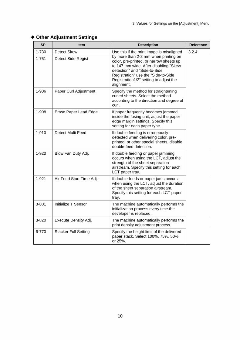
1 Blow Fan Duty Adj.
1. Using the [./*] key and [1-0] keys, enter the value you require for the setting, and then press the [#] key.
SP Item No Setting Default Maxim Minim Gradat Unit
Value um Value
um ion Value Value
001 A3/DLT LCT1 Upper Front
1-920 Blow Fan Duty Adj.
70 100 1 1 %
002 A3/DLT LCT1 Upper Rear
003 A3/DLT LCT1 Lower Front
004 A3/DLT LCT1 Lower Rear
005 A3/DLT LCT2 Upper Front
006 A3/DLT LCT2 Upper Rear
007 A3/DLT LCT2 Lower Front
008 A3/DLT LCT2 Lower Rear
24

3. Values for Settings on the [Adjustment] Menu
1 Air Feed Start Time Adj.
1. Using the [./*] key and [1-0] keys, enter the value you require for the setting, and then press the [#] key.
SP Item No Setting Default Maxim Minim Gradat Unit
Value um Value
um ion Value Value
001 A3/DLT LCT1 Upper Tray
1-921 Air Feed Start Time Adj.
3 10 1 1 sec
002 A3/DLT LCT1 Lower Tray
003 A3/DLT LCT2 Upper Tray
004 A3/DLT LCT2 Lower Tray
25

3. Values for Settings on the [Adjustment] Menu
1 Initialize T Sensor
1. 2.
Press the color to initialize the sensor, and then press the [#] key. If you press [Execute], the machine carries out initialization every time the developer is replaced.
SP Item No. Setting Selection Default Value
007 Color Selection Yellow, Magenta, Cyan, Black
Yellow, Magenta, Cyan, Black
3-801 Initialize T Sensor
008 Execute Execute -
1 Execute Density Adj.
SP Item No. Setting Selection Default Value
3-820 Execute Density Adj.
002 - Execute -
26

3. Values for Settings on the [Adjustment] Menu
1 Stacker Full Setting
1. Using the [./*] key and [1-0] keys, enter the value you require for the setting, and then press the [#] key.
SP Item No. Setting Selection Default Value
6-770 Stacker Full Setting 001 - 0: 100% 0: 100%
1: 75%
2: 50%
3: 25%
27

4. Using the [Adjustment Settings for Skilled Operators] Menu
4. Using the [Adjustment Settings for Skilled Operators] Menu
You can specify some of the items that are available on the [Adjustment] menu on the [Adjustment Settings for Skilled Operators] menu also.
4.1 Preparation: Displaying the [Adjustment Settings for Skilled Operators] menu
To use the [Adjustment Settings for Skilled Operators] menu, you must first configure your machine's [Administrator Authentication Management] setting. 1. Press [User Tools] key on the control panel. 2. Press [System Settings] on the display.
3. Press [Administrator Tools].
28

4. Using the [Adjustment Settings for Skilled Operators] Menu
4. Press [Administrator Authentication Management].
If any keys cannot be selected on the display, press [ Next].
5. Press [Machine Management].
6. Select [On] for "Admin. Authentication". 7. Press [OK].
29
4. Using the [Adjustment Settings for Skilled Operators] Menu
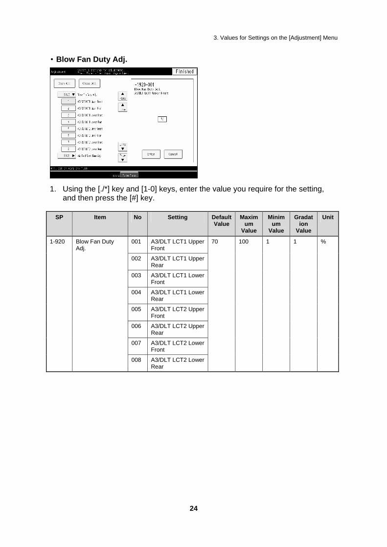
8. Press [Exit].
[Adjustment Settings for Skilled Operators] appears.
30

4. Using the [Adjustment Settings for Skilled Operators] Menu
4.2 Change the [Adjustment Settings for Skilled Operators] Mode
1. 2.
Press [Adjustment Settings for Skilled Operators]. Press [Login].
3. Enter your login user name, and then press [OK]. If you are logging on as the administrator for the first time, enter "admin".
4. Enter your login password, and then press [OK].
31

4. Using the [Adjustment Settings for Skilled Operators] Menu
5. Enter your login password again, and then press [OK]. The screen appears for Adjustment Settings for Skilled Operators Mode.
32

4. Using the [Adjustment Settings for Skilled Operators] Menu
4.3 Values for Settings on the [Adjustment Settings for Skilled Operators] Menu
For details about each setting in this menu, see the corresponding SP number in "3. Values for Settings in the [Adjustment] Menu". Although setting names might differ, matching numbers indicate the same function.
SP Item
1-920 Wide LCT Fan Duty Adj
1-921 Wide LCT Fan Start Time Settings
2-255 Developer Exhaust
2-256 Developer Fill
2-311 Manual Lubrication Exe
3-801 Init TD Sensor
3-820 Manual ProCon
6-700 Staple Position Adjustment
6-705 Punch Hole Position Adjustment
6-710 (6-755) End Bind Jogger Adjustment
6-715 (6-760) Adjust Output Jog Position
6-720 (6-710) Adjust Leading Edge Stopper Press
6-730 (6-715) Adjust Booklet Stapling Position
6-735 (6-720) Adjust Booklet Fold Position
6-740 Fine Adj Booklet Adjust Across
6-745 Booklet Fold Repetitions
6-755 Fold Position Fine Adjustment
6-760 Fold Position Fine Adjustment
6-770 Stack Full Setting
6-780 Cover Centering Adjustment
6-781 Cover Horizontal Position Adjustment
6-782 Finishing Angle Adjustment
The numbers in parentheses are the [Adjustment] menu numbers.
33

Index A J Adj Leading edge stopper press, 9, 16 Jogger Adjustments, 9, 16 Adj. Booklet Stapling Pos., 9, 17 L Adjust Output jog Position, 9, 16
Leading Edge Registration1, 8, 11, 12 C Leading Edge Registration2, 8, 11, 12 [Close All], 6 O Cover Center Pos. Adj., 14 Cover Centering Adjustment, 9 [Open All], 6 Cover Regist. Pos. Adj., 9, 14 Other Adjustment Settings, 10, 18 D P Detect Multi Feed, 10, 23 Paper Curl Adjustment, 10, 20 Detect Side Regist, 10, 19 Punch Hole Position Adjustment, 9 Detect Skew, 10, 18 Punch Pos. Adj. (V), 13 E S End Bind Jogger Adj, 9, 17 Shift Image Adjustment, 8, 11 [Exit], 6 Side-to-Side Registration1, 8, 11, 12
Side-to-Side Registration2, 8, 11, 12 F Sorting, 6 Fine Adjust Booklet Adjust Across, 9, 13 Stacker Full Setting, 10, 27 Finishing Position Adjustments, 9, 13 Staple Pos. Adj., 13 Fold Pos. Adj., 9, 14 Staple Position Adjustment, 9
[System Status], 6 I Z Items of Settings, 6 Z Fold Pos. Fine Adj (End), 9, 14 Z Fold Pos. Fine Adj (Frm), 9, 14
34

Copyright © 2008
EN USA G178-9505
35


Replacement Guide: TCRU
Model Name:
Pro C900s/Pro C900
1

CONVENTIONS USED IN THIS MANUAL
CAUTIONS, NOTES, ETC. The following headings provide important information that you must read:
RWARNING
Failure to follow the information could result in serious injury or death.
RCAUTION Follow the information to ensure safe operation and avoid minor injuries.
Important: • Follow this information to avoid misfeeds and loss of data, and to prevent
damage to the machine and originals. • The manufacturer shall not be responsible for any damage or expense that might
result from use of other than genuine parts with this machine. • Some illustrations in this manual might be slightly different from the machine.
Certain options might not be available in some countries. For details, please contact your local dealer.
Note: This information provides extra information about machine maintenance. Trademark: • Acrobat® is a registered trademark of Adobe Systems Incorporated. • EFI, Fiery and Fiery Driven are registered trademarks of Electronics for Imaging,
Inc. in the U.S. Patent and Trademark Office and/or certain other foreign jurisdictions.
GENERAL SAFETY INSTRUCTIONS Switches and Symbols Where symbols are used on or near switches on machines for Europe and other areas, the meaning of each symbol conforms with IEC60417.
ON
STANDBY
2

Power Plug and Power Cord
1.
2.
3.
4.
5.
6.
7. 8.
Always make sure that the power plug is fully completely into the wall outlet. A partially inserted plug could lead to heat generation (due to a power surge caused by high resistance) that can result in fire and other problems. Always check the power plug and make sure that it is free of dust and lint. Clean it if necessary. A dirty plug can generate heat that can result in fire. Inspect the length of the power cord for cuts or other damage. A frayed or otherwise damaged power cord can cause a short circuit which could lead to a fire or injury from electrical shock. If the power cord is damaged in any way, call for service. Check the length of the power cord between the machine and power supply. Make sure the power cord is not coiled or wrapped around any object such as a table leg. Coiling the power cord can cause excessive heat to build up and this could result in fire. Make sure that the area around the wall outlet is free of obstacles so the power cord can be removed quickly in case of an emergency. Make sure that the power cord is grounded (earthed) at the wall outlet using the ground wire on the plug. Insert the power cord into the wall outlet directly. Never use an extension cord. When disconnecting the power plug from the wall outlet, always pull on the plug, not the cable.
3

RWARNING
• Protect the machine from dampness or wet weather, such as rain and snow. • Unplug the power cord from the wall outlet before moving the machine. While moving
the machine, take care that the power cord is not damaged under the machine. • When disconnecting the power plug from the wall outlet, always pull the plug (not the
cable). • Do not allow paper clips, staples, or other small metallic objects to fall inside the
machine. • Keep toner (used or unused) and toner containers out of reach of children. • For environmental reasons, do not dispose of the machine or expended supply waste
at household waste collection points. Disposal can take place at an authorized dealer.
• The inside of this machine gets very hot. Do not touch the parts with a label indicating the “hot surface”. Otherwise, an injury might occur.
• The fusing section of this machine gets very hot. Caution should be taken when removing misfed paper.
• Keep the machine away from humidity and dust. Otherwise a fire or an electric shock might occur.
• Do not place the machine on an unstable or tilted surface. If it topples over, an injury might occur.
• Do not use aluminum foil, carbon paper, or similar conductive paper to avoid a fire or machine failure.
• If you use the machine in a confined space, make sure there is a continuous air turnover.
• If toner or used toner is inhaled, gargle with plenty of water and move into a fresh air environment. Consult a doctor if necessary.
• If toner or used toner gets into eyes, wash eyes immediately using lots of water. Consult a doctor if necessary.
• If toner or used toner is swallowed, dilute it by drinking lots of water. Consult a doctor if necessary.
• Avoid getting toner on your clothes or skin when removing a paper jam or replacing toner. If your skin comes into contact with toner, wash the affected area thoroughly with soap and water.
• If toner gets on your clothing, wash it using cold water. Hot water will set the toner into the fabric and might make removing the stain impossible.
SAFETY AND ECOLOGICAL NOTES FOR DISPOSAL 1. Do not incinerate toner bottles or used toner. Toner dust may ignite suddenly
when exposed to an open flame. 2. Dispose of used toner, developer, and organic photoconductors in
accordance with local regulations. (These are non-toxic supplies.) 3. Dispose of replaced parts in accordance with local regulations.
4

Table of Contents CONVENTIONS USED IN THIS MANUAL..........................................................2 GENERAL SAFETY INSTRUCTIONS.................................................................2
1. BEFORE YOU BEGIN… ..................................................................6
2. COMMON PROCEDURES...............................................................9 2.1 SWITCH THE MACHINE OFF BEFORE BEGINNING ANY PROCEDURE!.9 2.2 OPENING THE TCRU DISPLAY................................................................. 12 2.3 REMOVING THE FRONT TOP COVER...................................................... 15 2.4 REATTACHING THE FRONT TOP COVER ............................................... 16
3. CHARGE CORONA UNIT..............................................................17 3.1 REMOVING THE CHARGE CORONA UNIT............................................... 17 3.2 REINSTALLING THE CHARGE CORONA UNIT ........................................ 20
4. DRUM CLEANING UNIT................................................................22 4.1 REMOVING THE DRUM CLEANING UNIT................................................. 22 4.2 REINSTALLING THE DRUM CLEANING UNIT .......................................... 25
5. DRUM UNIT....................................................................................28 5.1 REMOVING THE DRUM UNIT.................................................................... 28 5.2 REINSTALLING THE DRUM UNIT ............................................................. 30
6. DEVELOPER..................................................................................33 6.1 REMOVING THE USED DEVELOPER ....................................................... 33 6.2 ADDING NEW DEVELOPER ...................................................................... 38
7. IMAGE TRANSFER BELT CLEANING UNIT ................................41 7.1 REMOVING THE IMAGE TRANSFER BELT CLEANING UNIT.................. 41 7.2 INSTALLING THE IMAGE TRANSFER BELT CLEANING UNIT ................ 44
8. PAPER TRANSFER ROLLER UNIT..............................................46 8.1 REMOVING THE PAPER TRANSFER ROLLER UNIT............................... 46 8.2 INSTALLING THE PAPER TRANSFER ROLLER UNIT.............................. 48
5

1. BEFORE YOU BEGIN… This manual is only operators who have received training in the procedures shown in this manual. General users are not to perform the procedures shown in this manual. • Never perform any procedure in this manual if you have not received proper
training. • If you have received training and are not sure about how to do a procedure then
call for service. • Even if you have received training, never attempt any procedure that is not
shown in this manual. • Contents of this manual are subject to change without prior notice. In no event
will the company be liable for direct, indirect, special, incidental, or consequential damages as a result of handling or operating this machine.
What You Need Use only the tools and materials described in this manual. Use of other tools or materials could damage the machine or cause injury.
RPG017S
Accessory hex driver Black hex screws
3 Developer bottle 4 Drum setting powder pad applicator
You will need the following items: • Accessory hex driver (provided). Needed to remove the black hex screws
from the machine. The black screws in the machine are the only screws that should be removed.
• Drum setting powder pad applicator (provided). Needed to apply a thin coated of powder on the drum.
• Newspaper or other paper. Needed to cover your work surface and prevent toner spillage from components removed from the machine.
Important: The accessory hex driver and drum setting powder pad are included in the kit that is supplied this machine. Keep this kit in a safe place where you can find it later. If the kit is not available, contact your supervisor or call for service.
6

NAMES OF COMPONENTS
RPG062S4
3
21
2
5
6
1. Toner hopper cover 2. Front top cover 3. Inner cover 4. Left front cover 5. Right front cover 6. Control panel Parts, Screw Color Codes • Handles and levers colored purple indicate where you should pull or lift a
component or part to move or remove it. • Black screws are the screws you must remove in order to remove the unit or
component. Never remove screws of any other color.
7

CONTROL PANEL
2
1
8
7
3
654 1. User Tools 2. Counter 3. Number keys 4. ./* key 5. Enter key 6. Clear key 7. On indicator 8. Operation Switch
8

2. COMMON PROCEDURES 2.1 SWITCH THE MACHINE OFF BEFORE BEGINNING
ANY PROCEDURE!
RWARNING • To prevent electrical shock, turn off the main power switch and
disconnect the ground wire from the machine and fixing heater.
Preparation Before performing any procedure shown in this manual, always do the following:
1. Press the [ ] tab.
2. Press [Restart Fiery].
3. Press [Shut Down].
9

4. Press [OK].
5. Press the operation switch to turn the machine off. 6. After turning off the operation switch, turn off the main power switch. 7. Wait a few seconds, and then disconnect the ground leakage circuit breaker
from the machine and fixing heater.
RPG069 8. The fusing unit becomes extremely hot during normal operation. After turning
the machine off and disconnecting the power cable and ground leakage circuit breaker, do not use the machine for at least 30 minutes. This time will allow the fusing unit to cool down.
The operation switch is on the control panel. (See "CONTROL PANEL".) The main power switch is in the upper left corner behind the front left cover.
10

SYSTEM AUTO RESET TIMER (TIMER SETTINGS)
The System Reset setting automatically switches the screen to that of the function specified in Function Priority if the machine is left idle for a specified period. • On • Off The setting should be “Off”. If you select "On", you can specify how long the machine waits before switching the screen. Using the number keys, you can specify a wait time of between 1 and 999 seconds. Note: For details about changing this setting, see General Setting Guide, which is
supplied with this machine.
11

2.2 OPENING THE TCRU DISPLAY
Overview • When installed, the TCRU SD card enables an LCD display application
specially designed for use with TCRU machines. • The TCRU SD card can be installed on TCRU machines only. It will not
function with other models. • The LCD display application of the TCRU SD card is protected by a built-in
authentication function. This means that the LCD display application cannot be copied or moved.
RCAUTION Any attempt to copy or move the LCD application will permanently disable the TCRU SD card.
12

INSTALLATION, TCRU SETUP
1. 2.
3.
4.
Insert the TCRU SD card into a vacant SD card slot on the back of the machine. After connecting the ground leakage circuit breaker to the machine and fixing heater, turn the machine on and wait for it to warm up. Press the [fierydriven] key on the control panel to display the main menu. Note: The [fierydriven] key on the control panel functions as a toggle to rotate the displays on the LCD: Main Menu > Printer function > Main Menu.
Press the [TCRU] button to display the TCRU Menu. The TCRU Menu is shown below.
Note: The [Fusing Unit] and [Others] buttons are not to be used in any of the procedures shown in this manual.
13

TCRU MENU SUMMARY
This section explains the functions of the buttons on the TCRU Menu. The menu displayed under each button in the TCRU menu The function menu is shown below.
Note: The following is based on the charge corona unit function menu. 1.
2.
3.
[Display PM Counter] buttons There is a [Display PM Counter] button for each unit. When a [Display PM Counter] button is pressed, the counter of that unit is displayed. Press the [Confirm] button to return to the previous display.
[Reset PM Counter] buttons There is a [Reset PM Counter] button for each unit. If a [Reset PM Counter] button is pressed, the machine performs initialization for the selected unit and clears the counter for that unit. • If an error occurs during the counter clear/initialization, an error message is
displayed. • If the counter clear/initialization completes successfully, "Counters have
been reset." is displayed. [PM Counter Log] buttons There is a [PM Counter Log] button for each unit. By pressing the [PM Counter Log] button, you can check the last two counter values before the counter was cleared. By pressing the [Confirm] button, you can check the earlier counter values also.
You can remove the TCRU SD card even when the machine is on.
14

2.3 REMOVING THE FRONT TOP COVER Procedure
1. Open the left (2) and right (1) front covers.
2
RPG020S
1
2. Open the toner hopper cover (1).
RPG003S
1
3.
4.
Remove the two screws at (1) and (2) by hand. Note: Use a coin to turn the screws if they are too tight to turn by hand.
Lift up the front top cover (3) and remove it.
RPG056S
1
3
2
15
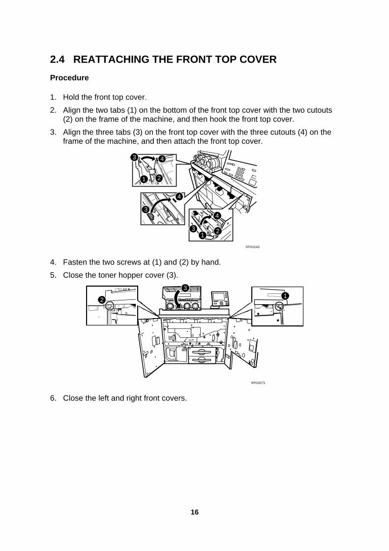
2.4 REATTACHING THE FRONT TOP COVER Procedure
1. Hold the front top cover. 2. Align the two tabs (1) on the bottom of the front top cover with the two cutouts
(2) on the frame of the machine, and then hook the front top cover. 3. Align the three tabs (3) on the front top cover with the three cutouts (4) on the
frame of the machine, and then attach the front top cover.
3
21
3 4
4
4
31
2
RPG014S
4. Fasten the two screws at (1) and (2) by hand. 5. Close the toner hopper cover (3).
RPG057S
13
2
6. Close the left and right front covers.
16

3. CHARGE CORONA UNIT 3.1 REMOVING THE CHARGE CORONA UNIT What You Need • Accessory hex driver provided with the machine. • Newspaper or other paper covering a nearby flat surface on which you can place
removed components.
RWARNING • To prevent electrical shock, switch off the main power switch and
disconnect the ground wire from the machine and fixing heater.
Replacement Message
Replacement of Charger is now necessary.
Replace Charger.
If this message appears, use the following procedure to replace the unit.
Preparation: Print out the counter list. 1.
2.
Press the [Counter] key on the control panel (see "CONTROL PANEL") and print out the counter list.
Switch the machine off. (See "SWITCH THE MACHINE OFF BEFORE BEGINNING ANY PROCEDURE!")
17
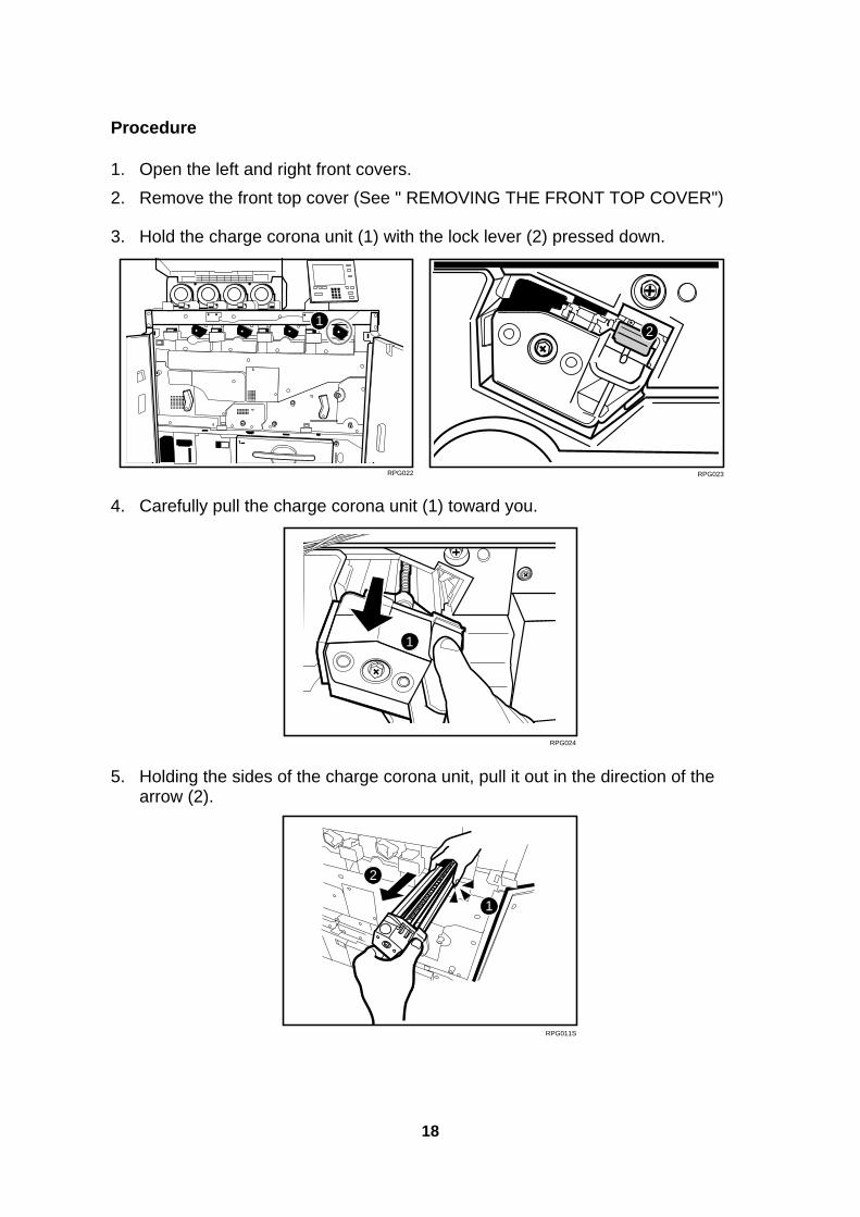
Procedure
1. 2.
3.
Open the left and right front covers. Remove the front top cover (See " REMOVING THE FRONT TOP COVER")
Hold the charge corona unit (1) with the lock lever (2) pressed down.
RPG022
12
RPG023
4. Carefully pull the charge corona unit (1) toward you.
RPG024
1
5. Holding the sides of the charge corona unit, pull it out in the direction of the arrow (2).
RPG011S
1
2
18

Important: To protect the charge corona unit from fingerprints, scratches, and dust:
• Always hold the charge corona unit (1) with both hands. • Never touch the wire mesh (2) below. • Never allow anything to touch the wire mesh while the charge corona unit is
outside the machine.
RPG012S
2
1
6. Lay the charge corona unit with the wire mesh facing down.
RPG025
19

3.2 REINSTALLING THE CHARGE CORONA UNIT Important: To protect the charge corona unit from fingerprints, scratches, and dust: • Never touch the wire mesh on the underside of the charge corona unit. • Never allow anything to touch the wire mesh while the charge corona unit is
outside the machine. Procedure
1. While holding the charge corona unit with both hands and with the wire mesh facing down, set the charge corona unit (1) on its rails (2) , and then carefully push it in until it can go no further.
RPG010S
2
2
1
2.
3. 4.
5. 6.
Reattach the front top cover and close the toner hopper cover. (See "REATTACHING THE FRONT TOP COVER".) Reconnect the ground leakage circuit breaker for the machine and fixing heater. Press the main power switch to turn the machine on, close the left and right front cover, and then wait for the machine to warm up. Open the TCRU display. (See "OPENING THE TCRU DISPLAY".) Press the [Charge Corona Unit] button.
20

7. 8.
9.
Press the [Reset PM Counter] button of the item that is the corresponding color. If a confirmation message appears, press the [Continue] button. Note: The counter will be reset.
When the counter is reset, press the [Confirm] button.
21

4. DRUM CLEANING UNIT 4.1 REMOVING THE DRUM CLEANING UNIT What You Need • Accessory hex driver provided with the machine. • Newspaper or other paper covering a nearby flat surface on which you can place
removed components.
RWARNING • To prevent electrical shock, switch off the main power switch and
disconnect the ground wire from the machine and fixing heater.
Replacement Message
Replacement of Cleaning Unit for PCU is now necessary. Replace Cleaning Unit for PCU.
If this message appears, use the following procedure to replace the unit.
Preparation: Print out the counter list. 1. Press the [Counter] key on the control panel (see "CONTROL PANEL") and
print out the counter list. 2. Switch the machine off. (See "SWITCH THE MACHINE OFF BEFORE
BEGINNING ANY PROCEDURE!") Procedure
1. Open the left and right front cover, open the toner hopper cover, and then remove the front top cover. (See "REMOVING THE FRONT TOP COVER".)
2. Remove the charge corona unit. (See "REMOVING THE CHARGE CORONA UNIT.)
3. Using the hex driver, remove the three black screws (1) from the inner cover (2) of the development unit drawer.
22

4. Remove the inner cover (2) of the development unit drawer.
RPG026
1
1
2
1
5. Loosen the drawer stop knob (1) by turning it counterclockwise, and then remove it.
RPG027
1
6. Holding the purple handle (1), carefully pull out the development unit drawer.
RPG028
1
Important: Do not leave the development unit drawer open for a long time. Also, do not expose the part where the drum unit is visible to direct sunlight.
23

7. Turn the drum cleaning unit lock lever (1) counterclockwise.
RPG029
1
8. Grasping both sides (1) of the drum cleaning unit as shown, lift the drum cleaning unit (2) straight up.
RPG007S
12
1
9. To avoid spilling toner, always carry the drum cleaning unit level with the exposed roller (1) facing up (not down).
1
RPG030
24

4.2 REINSTALLING THE DRUM CLEANING UNIT
Procedure Note: If you want to replace the drum unit with the drum cleaning unit, see
"DRUM UNIT".
1. Check the drum cleaning unit direction for reinstalling. • The waste toner collection pipe (1) should be at rear side.
RPG018S
1
2. Align the purple pin covers (1) at the front and rear edge of the drum cleaning unit with the guide rails (2), and then set the drum cleaning unit on the frame. Important: Never touch the green surface of the drum.
RPG004S
11
22
3. Turn the drum cleaning unit lock lever (1) clockwise until it clicks.
25

4. Gently and firmly push the purple handle (2) into the machine until the drawer can go no further and locks into place.
RPG032
1
2
Important: Do not pinch the harnesses (1) on the frame when pushing the development unit drawer into the machine.
RPG036
1
5. Install the drawer stop knob (1), and then fasten it by turning it clockwise.
RPG035
1
6.
7.
Attach the inner cover, and then secure it by turning its three black screws clockwise using the hex driver. Reinstall the charge corona unit. (See "REINSTALLING THE CHARGE CORONA UNIT")
26

8.
9. 10.
11. 12.
Reattach the front top cover and close the toner hopper cover. (See "REATTACHING THE FRONT TOP COVER".) Reconnect the ground leakage circuit breaker for the machine and fixing heater. Press the main power switch to turn the machine on, close the left and right front covers, and then wait for the machine to warm up. Open the TCRU Display. (See "OPENING THE TCRU DISPLAY".) Press the [Drum Cleaning Unit] button.
13. 14.
15.
Press the [Reset PM Counter] button of the item that is the corresponding color. If a confirmation message appears, press the [Continue] button. Note: The counter will be reset.
When the counter is reset, press the [Confirm] button.
27

5. DRUM UNIT 5.1 REMOVING THE DRUM UNIT What You Need • Accessory hex driver provided with the machine. • Newspaper or other paper covering a nearby flat surface on which you can place
removed components.
RWARNING • To prevent electrical shock, switch off the main power switch and
disconnect the ground wire from the machine and fixing heater.
Replacement Message
Replacement of Drum Unit is now necessary. Replace Drum Unit.
If this message appears, use the following procedure to replace the unit.
Preparation: Print out the counter list. 1. Press the [Counter] key on the control panel (see "CONTROL PANEL") and
print out the counter list. 2. Switch the machine off. (See "SWITCH THE MACHINE OFF BEFORE
BEGINNING ANY PROCEDURE!")
28

Procedure
1.
2.
3.
4.
Open the left and right front covers, open the hopper cover, and then remove the front top cover. (See "REMOVING THE FRONT TOP COVER".) Remove the charge corona unit. (See "REMOVING THE CHARGE CORONA UNIT.) Remove the drum cleaning unit. (See "REMOVING THE DRUM CLEANING UNIT".) Turn the drum lock nut (1) counterclockwise, and unlock the drum unit.
1
RPG063
5. Rotate the drum unit using its handle (1) as shown below, and then carefully pull out the drum unit.
RPG034
1
29

5.2 REINSTALLING THE DRUM UNIT
Procedure
Important: Never touch the green area of the drum.
1. Set the new drum unit (1) in the development unit drawer, and make sure that the two guides (2) (front) (3) (rear) at the development unit drawer are inserted securely in the grooves (4) (front) (5) (rear) at the drum unit.
RPG016S
4 14 5
32
2. Take the drum setting powder applicator out of the TCRU kit.
30

3. Using the powder pad applicator, pat the surface of the drum lightly.
25%
RPG019S
Important: • Setting powder must cover at least 25% of the surface of the drum to prevent
damage to the drum cleaning unit and the drum. • The setting powder is an inert substance that is not harmful to the human
body. 4. Fasten the drum lock nut (1) by turning it clockwise.
RPG033
1
5.
6.
7.
8.
9.
10.
Reinstall the drum cleaning unit and push the development unit drawer into the machine. (See "REINSTALLING THE DRUM CLEANING UNIT".) Install the drawer stop knob, and then fasten it clockwise. (See "REINSTALLING THE DRUM CLEANING UNIT".) Attach the inner cover, and then secure it by turning its three black screws clockwise using the hex driver. (See "REINSTALLING THE DRUM CLEANING UNIT".) Reinstall the charge corona unit. (See "REINSTALLING THE CHARGE CORONA UNIT") Reattach the front top cover and close the toner hopper cover. (See "REATTACHING THE FRONT TOP COVER".) Reconnect the ground leakage circuit breaker of the machine and fixing heater.
31

11.
12. 13.
Turn the machine's main power switch to ON, close the left and right front covers, and then wait for the machine to warm up. Open the TCRU Display. (See "OPENING THE TCRU DISPLAY".) Press the [Drum Unit] button.
14. 15.
16.
Press the [Reset PM Counter] button of the item that is the corresponding color. If a confirmation message appears, press the [Continue] button. Note: The counter will be reset.
When the counter is reset, press the [Confirm] button.
32

6. DEVELOPER 6.1 REMOVING THE USED DEVELOPER
Overview
You can remove the developer from more than one developer unit at a time. Important: Dispose of the developer bottle in accordance with the disposal regulations in your area.
What You Need • Developer bottle provided with the main machine.
RWARNING • Before replacing the developer, make sure that the machine's parts are
all closed.
Replacement Message
Replacement of Developer is now necessary. Replace Developer.
If this message appears, use the following procedure to replace the unit. Preparation: Print out the counter list.
1. Press the [Counter] key on the control panel (see "CONTROL PANEL") and print out the counter list.
Important: Before this procedure can be carried out, the machine must be switched on.
33

Procedure
1.
2.
Open the left and right front cover, open the toner hopper cover, and then remove the front top cover. (See "REMOVING THE FRONT TOP COVER".) Check that the developer you are preparing is the correct color by looking at the combination of the raised markings (1) on the shutter of the developer bottle. (The combination indicates the developer color, as shown below.)
RPG009S
1
3. 4.
5.
Check if the developer bottle is empty. Align the hole (1) of the bottle with the contact (2) under the outlet for the corresponding developer. Connect the developer bottle (3). Note: If you want to remove the developer from two or more development
units, connect empty bottles to the outlets of those units.
RPG060
3
12
34

6. Push the developer bottle to in the direction of the arrow (1) until it it can go no further and locks into place.
RPG054
1
7. 8.
Open the TCRU display. (See "OPENING THE TCRU DISPLAY".) Press the [Developer] button.
9. 10. 11. 12.
Press the [Reset PM Counter Developer:Exhaust] button. If a confirmation message appears, press the [Continue] button. Select the developer you want to replace, and then press the [Continue] button. If a confirmation message appears, press the [Continue] button. Note: The old developer is discharged.
35

13. After removing the developer, press the [Confirm] button, and then, while pressing the lock levers on either side of the developer bottle, carefully pull the bottle toward you.
Important: To avoid developer spillage while handling the developer bottle, always keep the developer bottle level.
RPG053
1
14.
15.
Disconnect the developer bottle from the developer outlet contact, and then remove it.
Important: Cover surrounding surfaces with paper. This will prevent spillage from the developer bottle spoiling them.
Remove the seal (1) that is stuck to the developer bottle.
RPG048
1
36

16. Attach the seal to the shutter (1) of the developer bottle, as shown.
Note: To prevent developer leaking during transport, cover the developer bottle's opening.
RPG049
1
Important: At this point, begin the procedure for adding the new developer. (See "ADDING NEW DEVELOPER")
37

6.2 ADDING NEW DEVELOPER Important: Be sure to switch the machine on before beginning this procedure. This procedure requires the machine to be powered. Procedure
1. Check that the developer you are preparing is the correct color by looking at the combination of the raised markings (1) on the shutter of the developer bottle. (The combination indicates the developer color, as shown below.)
RPG009S
1
2.
3.
Align the hole (1) of the bottle with the contact (2) on the inlet for the corresponding developer. Connect the developer bottle (3).
RPG059
2
1
3
38

4. Push the developer bottle in the direction of the arrow (1) until it can go no further and locks into place.
1
RPG051
5. Pull the seal (1) completely away.
RPG050
1
6. 7.
Open the TCRU display. (See "OPENING THE TCRU DISPLAY".) Press the [Developer] button.
8. 9. 10.
Press the [Reset PM Counter Developer:Reload] button. If a confirmation message appears, press the [Continue] button. Select the developer you want to replace, and then press the [Continue] button.
Note: The new developer begins pouring in.
39

11. When the confirmation message appears, press the [Confirm] button, and then, while pressing the lock levers on either side of the developer bottle, carefully pull the bottle toward you.
RPG052
1
12.
13. 14.
15.
Disconnect the developer bottle from the contact on the developer inlet, and then remove it. Turn the developer bottle upside down. Reattach the front top cover and close the toner hopper cover. (See "REATTACHING THE FRONT TOP COVER".) Close the left and right front cover.
40

7. IMAGE TRANSFER BELT CLEANING UNIT 7.1 REMOVING THE IMAGE TRANSFER BELT CLEANING
UNIT What You Need • Accessory hex driver provided with machine. • Newspaper or other paper covering a nearby flat surface on which you can place
removed components.
RWARNING • To prevent electrical shock, switch off the main power switch and
disconnect the ground wire from the machine and fixing heater.
Replacement Message
Intermed. Trans. Belt Cleaning Unit replacement is now required.
Replace Intermed. Trans. Belt Cleaning Unit.
If this message appears, use the following procedure to replace the unit.
Preparation: Print out the counter list. 1.
2.
Press the [Counter] key on the control panel (see "CONTROL PANEL") and print out the counter list. Switch the machine off. (See "SWITCH THE MACHINE OFF BEFORE BEGINNING ANY PROCEDURE!")
41

Procedure
1. 2.
3.
Open the left and right front covers. Remove the two black screws (1) on the inner cover (2) for the image transfer belt cleaning unit using the hex driver. Remove the inner cover (2). Note: To remove the inner cover, pull it out and slightly upward.
RPG044
21
1
4.
5.
Remove the black screw (1) on the image transfer belt cleaning unit using the hex driver. Rotate the cleaning blade contact lever (2) clockwise.
RPG038
12
6. Using the handle (1), carefully pull the image transfer belt cleaning unit toward you until it can go no further.
42

7. While pressing down the lock tab (1), carefully pull out the image transfer belt cleaning unit.
RPG039
1
Important: To avoid toner spillage while handling the image transfer belt cleaning unit, always keep the image transfer belt cleaning unit level.
RPG058
1
43

7.2 INSTALLING THE IMAGE TRANSFER BELT CLEANING UNIT
Procedure
1. While holding the image transfer belt cleaning unit with both hands, set the image transfer belt cleaning unit (1) on its rails (2), and then carefully push it in until it can go no further.
RPG040
2
RPG041
11
2
2.
3.
Fasten the black screw (1) on the image transfer belt cleaning unit using the hex driver. Rotate the cleaning blade contact lever (2) counterclockwise.
RPG037
12
4.
5. 6.
7.
Reattach the inner cover and then fasten the two black screws on the inner cover of the image transfer belt cleaning unit using the hex driver. (See "REMOVING THE IMAGE TRANSFER BELT CLEANING UNIT".) Reconnect the ground leakage circuit breaker for the machine and fixing heater. Press the main power switch to turn the machine on, close the left and right front cover, and then wait for the machine to warm up. Open the TCRU display. (See "OPENING THE TCRU DISPLAY".)
44

8. Press the [Image Transfer Belt Cleaning Unit] button.
9. 10.
11.
Press the [Reset PM Counter:Image Transfer Belt Cleaning Unit] button. If a confirmation message appears, press the [Continue] button. Note: The counter will be reset. When the counter is reset, press the [Confirm] button.
45

8. PAPER TRANSFER ROLLER UNIT 8.1 REMOVING THE PAPER TRANSFER ROLLER UNIT What You Need • Newspaper or other paper covering a nearby flat surface on which you can place
removed components.
RWARNING • To prevent electrical shock, switch off the main power switch and
disconnect the ground wire from the machine and fixing heater.
Replacement Message
Replacement of Transfer Unit is now necessary.
Replace Transfer Unit.
If this message appears, use the following procedure to replace the unit.
Preparation: Print out the counter list. 1.
2.
1. 2.
Press the [Counter] key on the control panel (see "CONTROL PANEL") and print out the counter list. Switch the machine off. (See "SWITCH THE MACHINE OFF BEFORE BEGINNING ANY PROCEDURE!")
Procedure
Open the left and right front cover. Rotate the lock lever (1) of the registration unit drawer counterclockwise, and then pull the drawer toward you.
1
RPG042
46

3.
4.
Using the hex driver, remove the black screw in the rear lock (1), and then slide the rear lock to the rear end. Using the hex driver, remove the black screw in the front lock (2), and then slide the front lock to the front end.
RPG065S
1
2
5. Holding the paper transfer roller unit (1) with both hands, carefully lift it up and out.
Important: To avoid toner spillage while handling the paper transfer roller unit, always keep the paper transfer roller unit level.
1
RPG046
47

8.2 INSTALLING THE PAPER TRANSFER ROLLER UNIT Procedure
1.
2. 3.
While holding the paper transfer roller unit (1) with both hands, align the stays (2) of the paper transfer roller unit with the shafts of the registration unit drawer, and then set the paper transfer roller unit on the registration unit drawer. Slide the rear lock (3) forward to align it with the shaft screw hole. Slide the front lock (4) backward to align it with the shaft screw hole.
RPG066S
3
1
2
42
Important: Install the paper transfer roller unit securely, as shown below.
RPG005S
48

4. Using the hex driver, turn the black screws to lock the front (1) and rear (2) locks.
RPG068S
2
RPG067S
1
5.
6.
Carefully the registration unit drawer into the machine until it can go no further and locks into place. Rotate the lock lever (1) of the registration unit drawer clockwise.
RPG043
1
7. 8.
9. 10.
Reconnect the ground leakage circuit breaker for the machine and fixing heater. Press the main power switch to turn the machine on, close the left and right front cover, and then wait for the machine to warm up. Open the TCRU display. (See "OPENING THE TCRU DISPLAY".) Press [Paper Transfer Roller Unit] button.
49

11. 12.
13.
Press the [Reset PM Counter:Paper Transfer Roller Unit] button. If a confirmation message appears, press the [Continue] button. Note: The counter will be reset. When the counter is reset, press the [Confirm] button.
Copyright © 2008
EN USA G178-9504
50

Troubleshooting: TCRU
Model Name:
Pro C900s/Pro C900
1

Table of Contents
1. BEFORE YOU BEGIN .........................................................................3 1.1 GUIDE TO COMPONENTS...........................................................................3 1.2 ADJUSTMENT: USING THE TCRU SD CARD.............................................4
2. TROUBLESHOOTING SERVICE CALL PROBLEMS (SC CODES) ..5 2.1 WHAT ARE SC CODES?..............................................................................5 2.2 SC CODE LIST..............................................................................................5
3. TROUBLESHOOTING IMAGE QUALITY PROBLEMS ......................7 3.1 IMAGE QUALITY PROBLEMS......................................................................7
3.1.1 PROBLEM 1: WHITE SPOTS ..............................................................7 3.1.2 PROBLEM 2: SHARP SPOTS .............................................................9 3.1.3 PROBLEM 3: VERTICAL STRIPES ................................................... 11 3.1.4 PROBLEM 4: DENSITY TOO LOW.................................................... 13 3.1.5 PROBLEM 5: DENSITY TOO HIGH................................................... 15 3.1.6 PROBLEM 6: DIRTY BACKGROUND................................................ 17 3.1.7 PROBLEM 7: PATCHY ...................................................................... 19 3.1.8 PROBLEM 8: STREAKS (1)............................................................... 21 3.1.9 PROBLEM 9: STREAKS (2)............................................................... 23
4. TROUBLESHOOTING PAPER DELIVERY PROBLEMS .................24
2

1. BEFORE YOU BEGIN If the machine will not print, does not print as expected, or exhibits any other problem, find the problem in this manual and troubleshoot accordingly.
RCAUTION Before you replace any unit: • Always turn the machine off and unplug the power cord from the power
source. • Let the machine sit idle for at least 10 minutes before you carry out any
procedures. This time allows time for the fusing unit to cool.
1.1 GUIDE TO COMPONENTS This section introduces the names of the components.
Refer to the following diagrams when replacing units or troubleshooting.
21 4 53 6 7 8 9
10
1. Development unit (Yellow) 2. OPC drum (Yellow) 3. Development unit (Magenta) 4. OPC drum (Magenta) 5. Development unit (Cyan) 6. OPC drum (Cyan) 7. Development unit (Black) 8. OPC drum (Black) 9. Charge corona unit 10. ITB (Image Transfer Belt)
3
1
2
4
3
Y M C K
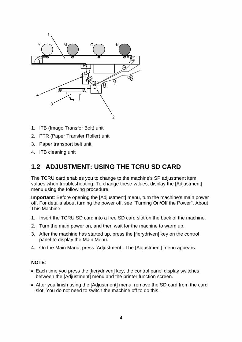
1. ITB (Image Transfer Belt) unit 2. PTR (Paper Transfer Roller) unit 3. Paper transport belt unit 4. ITB cleaning unit
1.2 ADJUSTMENT: USING THE TCRU SD CARD The TCRU card enables you to change to the machine's SP adjustment item values when troubleshooting. To change these values, display the [Adjustment] menu using the following procedure. Important: Before opening the [Adjustment] menu, turn the machine’s main power off. For details about turning the power off, see "Turning On/Off the Power", About This Machine.
1. Insert the TCRU SD card into a free SD card slot on the back of the machine. 2. Turn the main power on, and then wait for the machine to warm up. 3. After the machine has started up, press the [fierydriven] key on the control
panel to display the Main Menu. 4. On the Main Manu, press [Adjustment]. The [Adjustment] menu appears. NOTE:
• Each time you press the [fierydriven] key, the control panel display switches between the [Adjustment] menu and the printer function screen.
• After you finish using the [Adjustment] menu, remove the SD card from the card slot. You do not need to switch the machine off to do this.
4

2. TROUBLESHOOTING SERVICE CALL PROBLEMS (SC CODES)
2.1 WHAT ARE SC CODES? If an error occurs during operation, the machine displays an SC code ("SCnnn" , where "nnn" is a three-digit number). The machine stops and cannot be used when an SC code is displayed.
If an SC code appears:
1. Write down the SC number. 2. Turn off the main power switch.
NOTE: The main power switch is the switch on the lower left side of the machine under the hinged plastic cover.
3. Wait a few moments, then turn the machine on again. In most cases, cycling the machine off and on will restore it to full operation.
4. If the SC code reappears, check it against the table (see, 2.2 SC CODE LIST). Check for the SC code in the following table (see 2.2 SC CODE LIST). If the SC code is listed in the table, carry out the recommended procedure. -OR- If the SC CODE is not listed in the following table (see 2.2 SC CODE LIST), call for service.
2.2 SC CODE LIST This table contains a list of selected SC codes. If the SC code that is displayed on the control panel is listed in this table, carry out the recommended procedure. If the SC CODE is not listed in this table, call for service. Important: If the error persists after replacing the unit, call for service.
Code Error Procedure SC300 Charge corona wire high voltage error: K
Replace the black charge corona unit
SC301 Charge corona wire high voltage error: C
Replace the cyan charge corona unit.
SC302 Charge corona wire high voltage error: M
Replace the magenta charge corona unit.
SC303 Charge corona wire high voltage error: Y
Replace the yellow charge corona unit.
SC304 Charge grid high voltage error: K
Replace the black charge corona unit.
SC305 Charge grid high voltage error: C
Replace the cyan charge corona unit.
5

Code Error Procedure SC306 Charge grid high voltage error: M Replace the magenta charge corona
unit. SC307 Charge grid high voltage error: Y
Replace the yellow charge corona unit.
SC308 Charge cleaning unit: Position error: K Detach and reattach the black charge corona unit or replace it.
SC309 Charge cleaning unit: Position error: C Detach and reattach the cyan charge corona unit or replace it.
SC310 Charge cleaning unit: Position error: M Detach and reattach the magenta charge corona unit or replace it.
SC311 Charge cleaning unit: Position error: Y Detach and reattach the yellow charge corona unit or replace it.
SC420 Potential sensor error: Vd Adjustment K
Replace the black drum unit.
SC421 Potential sensor error: Vd Adjustment C
Replace the cyan drum unit.
SC422 Potential sensor error: Vd Adjustment M
Replace the magenta drum unit.
SC423 Potential sensor error: Vd Adjustment Y
Replace the yellow drum unit.
SC424 Potential sensor error: Vl adjustment K
Replace the black drum unit.
SC425 Potential sensor error: Vl adjustment C
Replace the cyan drum unit.
SC426 Potential sensor error: Vl adjustment M
Replace the magenta drum unit.
SC427 Potential sensor error: Vl adjustment Y
Replace the yellow drum unit.
SC432 Potential sensor error 1: Vr adjustment K
Replace the black drum unit.
SC433 Potential sensor error 2: Vr adjustment K
Replace the cyan drum unit.
SC434 Potential sensor error 3: Vr adjustment M
Replace the magenta drum unit.
SC435 Potential sensor error 4: Vr adjustment Y
Replace the yellow drum unit.
SC450 PTR HVPS output error Detach and reattach the paper transfer roller unit or replace it.
SC460 Separation HV output error Detach and reattach the paper transfer roller unit or replace it.
6
3. TROUBLESHOOTING IMAGE QUALITY PROBLEMS
This section describes some common image quality problems and tells you what to do about them. Paper Feed Direction Before you begin this section, note that the dark arrow in each illustration indicates the direction of paper feed.
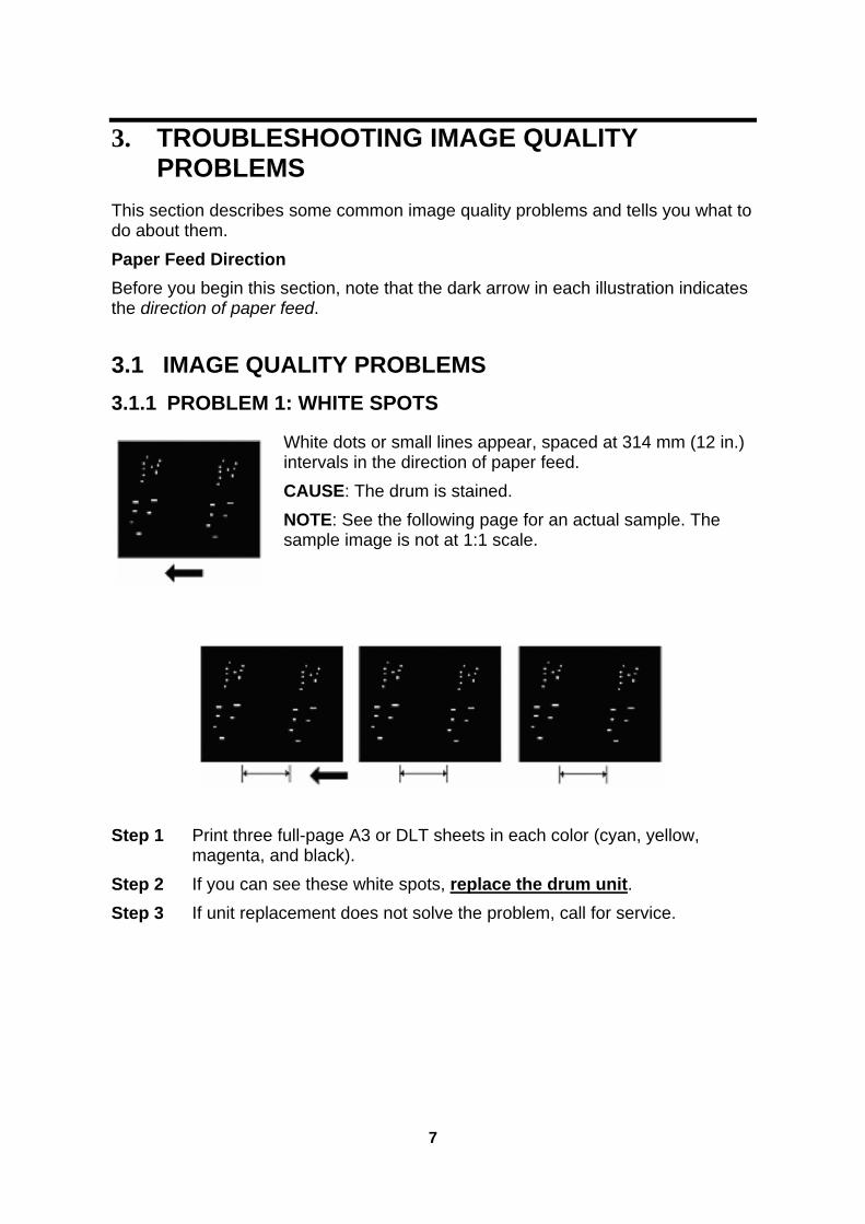
3.1 IMAGE QUALITY PROBLEMS 3.1.1 PROBLEM 1: WHITE SPOTS
White dots or small lines appear, spaced at 314 mm (12 in.) intervals in the direction of paper feed.
CAUSE: The drum is stained. NOTE: See the following page for an actual sample. The sample image is not at 1:1 scale.
Step 1 Print three full-page A3 or DLT sheets in each color (cyan, yellow,
magenta, and black). Step 2 If you can see these white spots, replace the drum unit. Step 3 If unit replacement does not solve the problem, call for service.
7

8

3.1.2 PROBLEM 2: SHARP SPOTS
These spots mark the page with very sharp dots at 314 mm (12 in.) intervals in the direction of paper feed. CAUSE: The drum unit has worn out or the drum is scratched. NOTE: See the following page for an actual sample. The sample image is not at 1:1 scale.
Step 1 Print three full-page A3 or DLT sheets in each color (cyan, yellow, magenta, and black).
Step 2 If these sharp spots appear on the sheets, replace the drum unit. Step 3 If replacing the drum unit does not solve the problem, call for service.
9

10

3.1.3 PROBLEM 3: VERTICAL STRIPES
Vertical stripes (less than 1 mm wide) appear, parallel to the direction of paper feed.
CAUSE: 1. The drum unit has worn out or the drum is scratched. 2. The blade of the drum cleaning unit has worn out and cannot clean properly. NOTE: See the following page for an actual sample. The sample image is not at 1:1 scale.
1. If the drum is scratched: Step 1 Replace the drum unit. Step 2 If replacing the drum unit does not solve the problem, call for service. 2. If the drum is not scratched but is stained with toner: Step 1 Replace the drum cleaning unit. Step 2 If replacing the drum cleaning unit does not solve the problem, call for
service.
11
12

3.1.4 PROBLEM 4: DENSITY TOO LOW
Sheets are too light, especially in areas of solid fill.
CAUSE: The density setting is too low. NOTE: See the following page for an actual sample. The sample image is not at 1:1 scale.
Step 1 In [Adjustment] menu, carry out 3-820-002 (Execute Density Adj). Step 2 If adjusting the density does not solve the problem, call for service.
13

14

3.1.5 PROBLEM 5: DENSITY TOO HIGH
Sheets are too dark, especially in areas of solid fill. CAUSE: The density setting is too high, or the developer has deteriorated. NOTE: See the following page for an actual sample. The sample image is not at 1:1 scale.
Step 1 In [Adjustment] menu, carry out 3-820-002 (Execute Density Adj). Step 2 Print a few sheets. Does the image density appear darker? Yes Finished! No Replace the developer.Step 3 If changing the developer does not solve the problem, call for service.
15
16

3.1.6 PROBLEM 6: DIRTY BACKGROUND
Random "powdered" dots appear, creating a dirty background.
CAUSE: The developer has deteriorated. NOTE: See the following page for an actual sample. The sample image is not at 1:1 scale.
Step 1 Replace the developer.Step 2 If changing the developer does not solve the problem, call for service.
17

18

3.1.7 PROBLEM 7: PATCHY
Printed sheets are patchy. CAUSE: The developer has deteriorated. NOTE: See the following page for an actual sample. The sample image is not at 1:1 scale.
Step 1 Print three full-page A3 or DLT sheets in each color (cyan, yellow,
magenta, and black). Step 2 If the sheets are patchy, replace the developer.Step 3 If changing the developer does not solve the problem, call for service.
19

20

3.1.8 PROBLEM 8: STREAKS (1)
Wide streaks appear in the direction of paper feed.
CAUSE: The electrical discharge from the charge corona unit is not constant. NOTE: See the following page for an actual sample. The sample image is not at 1:1 scale.
Step 1 In [Adjustment] menu, carry out SP 3-820-002 (Execute Density Adj).
NOTE: If you carry out “Execute Density Adj”, the machine cleans the charge corona unit.
Step 2 Print a few sheets. Is the problem solved? Yes Finished! No Replace the charge corona unit.Step 3 If replacing the charge corona unit does not solve the problem, call for
service.
21

22

3.1.9 PROBLEM 9: STREAKS (2)
When printing on one side only, toner streaks appear only on the printed side or only on the back. Toner streaks appear even when printing only in cyan, magenta, yellow, or black. CAUSE: 1. The image transfer belt cleaning unit is faulty. 2. The paper transfer roller unit is faulty.
1. If toner streaks appear only on the printed side of sheets: Step 1 Replace the image transfer belt cleaning unit.Step 2 If replacing the image transfer belt cleaning unit does not solve the
problem, call for service. 2. If toner streaks appear only on the back of sheets: Step 1 Replace the paper transfer roller unit.Step 2 If replacing the paper transfer roller unit does not solve the problem,
call for service.
23

4. TROUBLESHOOTING PAPER DELIVERY PROBLEMS
Important: For details about the items displayed in [Adjustment] menu, see the Adjustment Item Menu Guide.
Problem Cause Solution Sheets cannot be delivered.
The ends of the sheets are slightly curled.
Remove the sheets from the paper tray, flatten and fan them thoroughly, and then put them back into the paper tray.
The tray's paper setting does not match the size of the paper loaded in the tray.
Change the tray's paper setting so it matches the size of the loaded paper.
Sheets of an undetectable type, such as color or preprinted sheets, are being used.
In [Adjustment] menu, select [Detect Side Regist] and [Detect Skew] to disable side-to-side registration and skew detection, and then adjust the image position in [Side-to-Side Registration]. Do this for each affected tray.
The paper size cannot be detected because sheets no wider than 147 mm (approx. 5.787") are being used.
To print on narrow sheets (139.7-147 mm [approx. 5.5-5.787 in.]), in [Adjustment] menu, select [Detect Side Regist] and [Detect Skew] to disable side-to-side registration and skew detection, and then adjust the image position in [Side-to-Side Registration]. Do this for each affected tray.
The ends of the sheets are slightly curled.
Remove the sheets from the paper tray, flatten and fan them thoroughly, and then put them back into the paper tray.
The tray’s paper guides are not adjusted correctly.
Adjust the tray's side paper guides and end paper guide according to the paper size.
Sheets are delivered skewed.
Paper or a paper fragment is jammed inside the machine.
Remove the jammed paper.
Sheets of an undetectable type, such as color or preprinted sheets, are being used.
In [Adjustment] menu, select [Detect Side Regist] and [Detect Skew] to disable side-to-side registration and skew detection, and then adjust the image position in [Side-to-Side Registration]. Do this for each affected tray.
The side-to-side registration is wrong.
The paper size cannot be detected because sheets no wider than 147 mm (approx. 5.787") are being used.
When printing on narrow sheets (139.7-147 mm [approx. 5.5-5.787 in.]), in [Adjustment] menu, select [Detect Side Regist] and [Detect Skew] to disable side-to-side registration and skew detection, and then adjust the image position in [Side-to-Side Registration]. Do this for each affected tray.
24

Problem Cause Solution The ends of the sheets are slightly curled.
Remove the sheets from the paper tray, flatten and fan them thoroughly, and then put them back into the paper tray.
Sheets of differing paper types or thickness are loaded in the same paper tray.
Removed mixed sheets from the paper tray, and then reload the paper tray with sheets of one type and thickness only.
Multiple sheets feed in at once.
Sheets of an undetectable type, such as color or preprinted sheets, are being used.
In [Adjustment] menu, select [Detect Multi Feed] to disable multi-feed detection.
Sheets are not loaded correctly in the tray.
Set paper in the tray correctly. Sheets are delivered with bent corners.
Excessively curled sheets are being used.
In [Adjustment] menu, specify [Paper Curl Adjustment] to flatten out the sheets.
Sheets are delivered curled.
Excessively curled sheets are being used.
In [Adjustment] menu, specify [Paper Curl Adjustment] to flatten out the sheets.
Copyright © 2008
EN USA G178-9506
25

![Operating Instructions - TCRU Adjustment: Aegis-P1, AG …rfg-esource.ricoh-usa.com/stellent/groups/public/documents/service... · [Adjustment Item] Menu Guide Model Name: Pro C900](https://static.fdocuments.in/doc/165x107/5abe57ba7f8b9aa3088cbe09/operating-instructions-tcru-adjustment-aegis-p1-ag-rfg-adjustment-item.jpg)