ADJUSTMENT FLOW CHART
19
ADJUSTMENT FLOW CHART 1. Disconnect the antenna from the receiver or transceiver. 2. Adjust R4 (50K) to get 4 Volts at IC LM324 Pin 3. 3. Adjust R3A ( 50K) to see full scale deflection on VU Meter. 4. Now Adjust R5 (5K) to get the VU Meter to show ZERO. 5. Now connect the antenna. Tune for a strong signal. Adjust R3A(50K) to show Full Scale on meter. 6. Now Adjust AGC level with R7 for a comfortable level of audio 7. Finally, Adjust R3 (10K) for VU Meter movement that should show a steady movement of meter level and not a wide variation in meter movement. A 3 PIN Connector is provided to either use berg pins with jumper or a switch, for slow OR fast AGC It is suggested not to directly solder the VU meter on the PCB. Connect VU meter with PCB with wires, this is suggested as sometimes the VU meter can get faulty and soldering and de soldering on the pcb pads may damage the pcb.
Transcript of ADJUSTMENT FLOW CHART

ADJUSTMENT FLOW CHART
1. Disconnect the antenna from the receiver or transceiver.2. Adjust R4 (50K) to get 4 Volts at IC LM324 Pin 3.3. Adjust R3A ( 50K) to see full scale deflection on VU Meter.4. Now Adjust R5 (5K) to get the VU Meter to show ZERO.5. Now connect the antenna. Tune for a strong signal. Adjust R3A(50K)
to show Full Scale on meter.6. Now Adjust AGC level with R7 for a comfortable level of audio 7. Finally, Adjust R3 (10K) for VU Meter movement that should show a
steady movement of meter level and not a wide variation in meter movement.
A 3 PIN Connector is provided to either use berg pins with jumper or a switch, for slow OR fast AGC
It is suggested not to directly solder the VU meter on the PCB. Connect VU meter with PCB with wires, this is suggested as sometimes the VU meter can get faulty and soldering and de soldering on the pcb pads may damage the pcb.

2
31
IC1A
6
57
IC1B9
108
IC1C
13
1214
IC1D
D1R1
C1
AE
SR3A
AE
SR3
AE
SR4
AE
SR5
LED-1LED-2
IF-1
IF-2
12V-1
12V-2
AUDIO-1AUDIO-2
C3
D2
R6
C4
D3
R8
R9 R10
R11
R12
R13 R14
C5 R15
AE
SR7R16
T1
411
C2
R2
SM1
SM2
JP1
1 2 3
H1
+
+
+
+
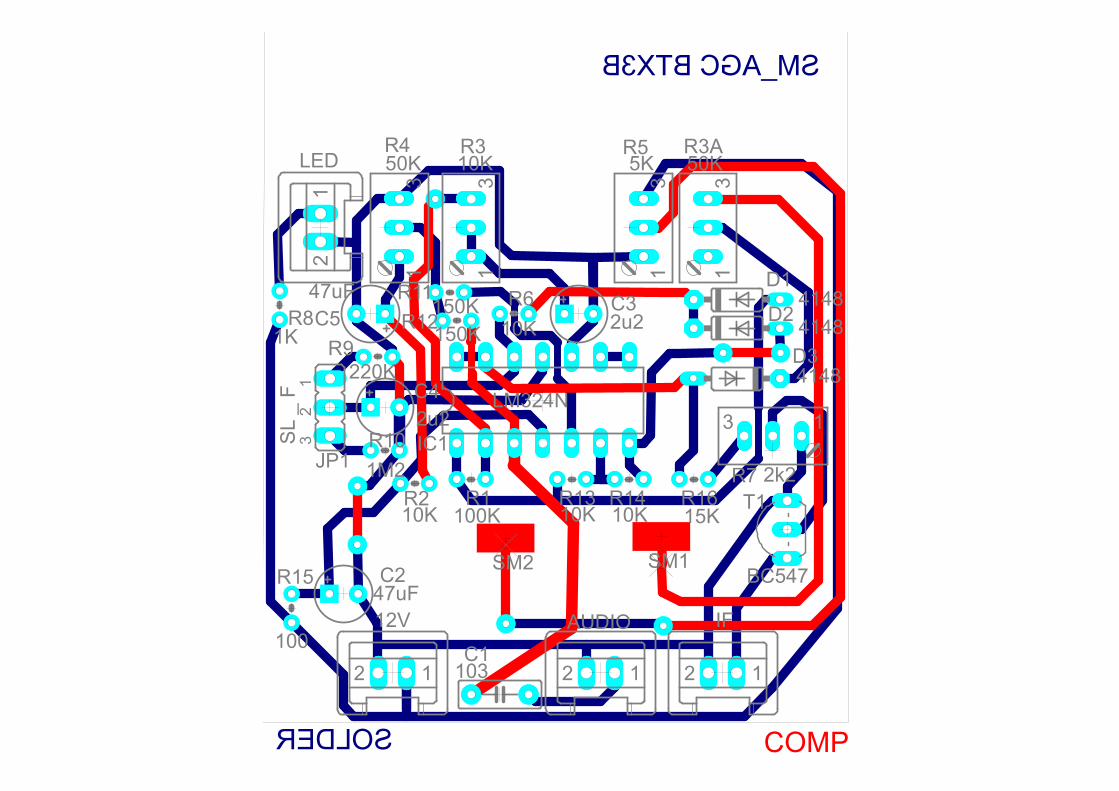
SM_AGC BTX3B
SOLDER COMP3
1
31
31
31
12
1212 12
3 1
12
3 IC1
D1
R1
C1
R3AR3R4 R5LED
IF12V AUDIO
C3 D2R6
C4
D3
R8R9
R10
R11R12
R13 R14
C5
R15
R7R16 T1
C2
R2
SM1SM2
JP1
LM324N
4148
100K
103
50K10K50K 5K
2u2 414810K
2u2
4148
1K
220K
1M2
150K150K
10K 10K
47uF
100
2k2
15K
BC54747uF
10K
SL
_ F

31
31
31
31
12
1212 12
3 1
12
3 IC1
D1
R1
C1
R3AR3R4 R5
IF12V AUDIO
C3
D2R6
C4 D3
R8 R9
R10
R11R12
R13 R14
C5
R15
R7R16
T1R2
SM1SM2
JP1

AGC Complete Built
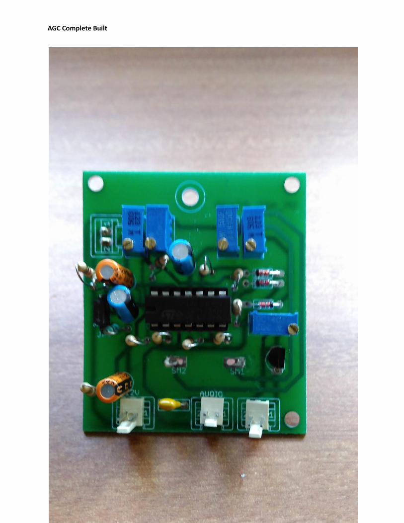
AGC Complete Built
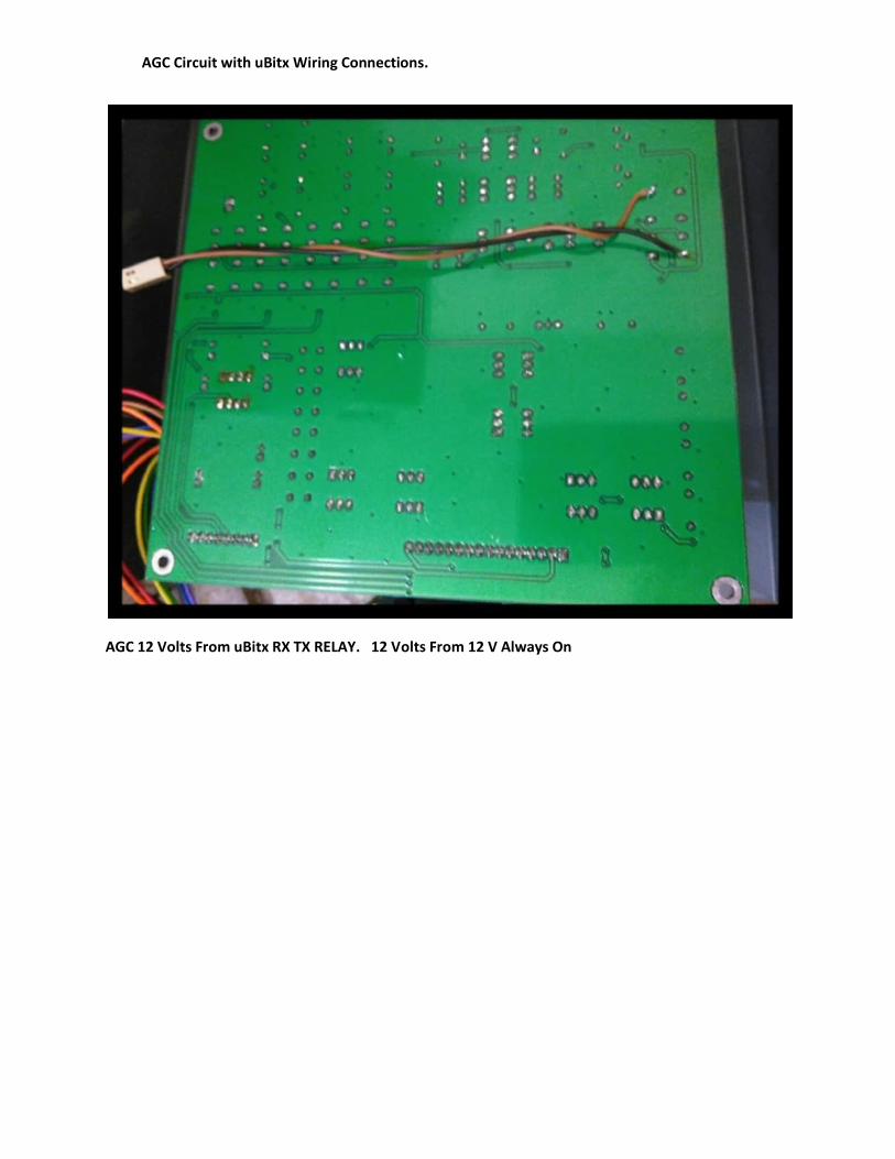
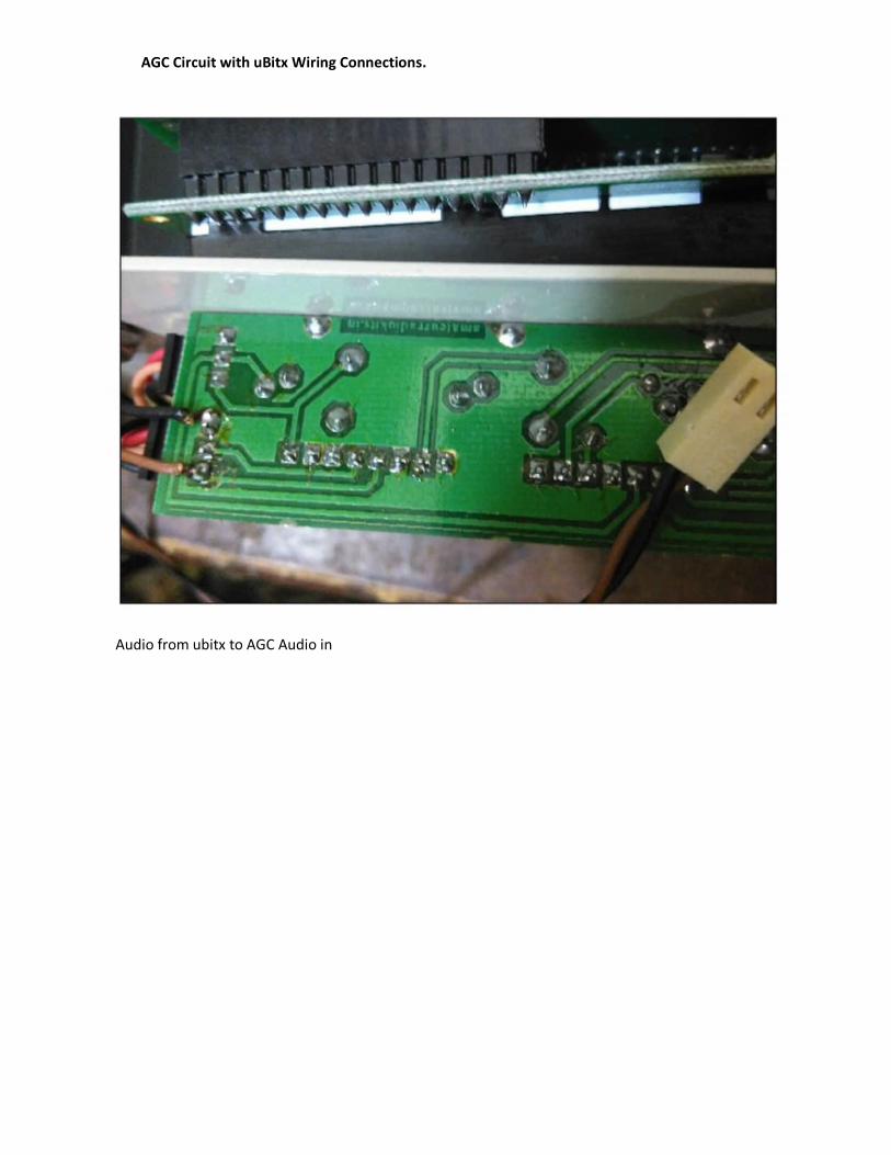
AGC Circuit with uBitx Wiring Connections.
AGC 12 Volts From uBitx RX TX RELAY. 12 Volts From 12 V Always On

AGC Circuit with uBitx Wiring Connections.
First IF Stage Q10. AGC Line

AGC Circuit with uBitx Wiring Connections.
AGC Line Connected with uBitx First IF
AUDIO FROM UBITX TO AGC
AGC Circuit with uBitx Wiring Connections.
Audio from ubitx to AGC Audio in

NEW BITX AGC Adjustments Updates
August 09, 2016
Lately many Hams who purchased the AGC kit with our Bitx Kit were having some problem
in adjusting the
VU meter to get a deflection. After observing the problem sometimes at my end too i decided
to study what would be the correct sequence to set the VU meter.
The setting of 2 trimmers R3A And R5 were found determining the initial settings of the VU
meter.
After doing some adjustments with R3A And R5 the correct settings were found as to my
way, there can be other ways too.
Below I have provided a silkscreen picture of AGC and short notes to be followed in
sequence.
I hope this should help many struggling with setting their meter to move and complete their
AGC.
Any one can contact to me if he find still his AGC is not working.
Now Please follow the setting of AGC Meter as below.

AGC ADJUSTMENTS UPDATED
First disconnect antenna from the transceiver or any receiver being used with the AGC
module.Also switch the AGC module off from the power source.
Now follow the steps below in sequence to adjust the AGC settings below:
STEP 1: Set point A and B as shown in Fig 1: AGC silkscreen with trimmer R5 (5K) to 4.9k by
tuning the trimmer anti clockwise, use any DMM for this setting. The multi meter leads
to be connected between point A and B. We need more adjustment with this trimmer later
on. Steps to be followed in sequence leave it at this setting for now.

STEP 2: Set point C and D as shown in Fig 1: with trimmer R3A 50K to ZERO 0 ohms by tuning
the trimmer clockwise, use any DMM for this setting. The multi meter leads to be
connected between point C and D, we need more adjustment with this trimmer later in
steps to be followed in sequence.
STEP 3:
Now connect +12 Volts power to AGC, and adjust trimmer R4 (50K)
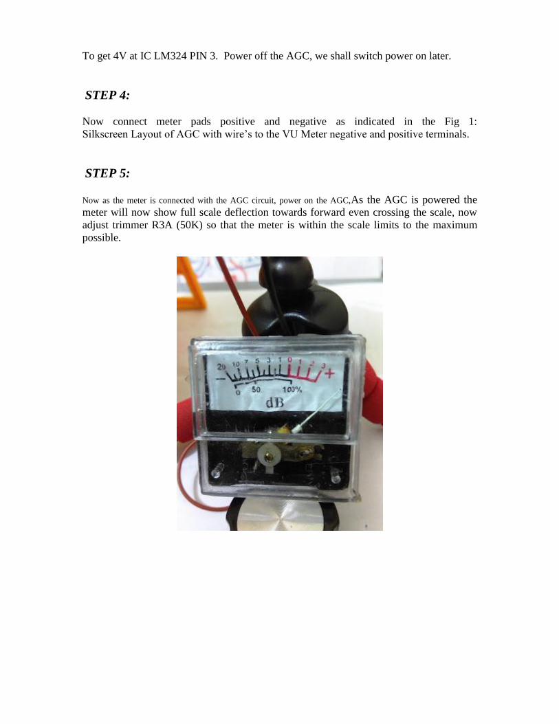
To get 4V at IC LM324 PIN 3. Power off the AGC, we shall switch power on later.
STEP 4:
Now connect meter pads positive and negative as indicated in the Fig 1:
Silkscreen Layout of AGC with wire’s to the VU Meter negative and positive terminals.
STEP 5:
Now as the meter is connected with the AGC circuit, power on the AGC,As the AGC is powered the
meter will now show full scale deflection towards forward even crossing the scale, now
adjust trimmer R3A (50K) so that the meter is within the scale limits to the maximum
possible.

The meter is at max forward position
STEP 6:
Now adjust R5 (5K ) to get meter to show near to zero reading on the meter, but not
absolute zero reading, this setting can be adjusted later to see how the meter responds to
a signal. If you see a slack movement moves the setting above a bit zero. This can be
tried with trail and error to see at which point the meter is excited best.


The meter setting has been bought near to zero with adjusting R5 (5)
Optimum Zero position for VU meter set
STEP 7:
Now is the time to connect the antenna to your set, tune for a strong signal and adjustR3A
(50K) to show Full Scale meter reading.
STEP 8:
Now adjust AGC level with R7 (2.2K) for a Comfortable Audio.
STEP 9:
Finally Adjust R3 (10K) for VU Meter movement NOT to jump, but show rather
Steady levels.
AND THAT’S IT ………

AGC AND S. METER COMPONENTS LIST
VALUE TYPE QUANTITY CODE
100 E RESISTOR 0.25 W 1 BROWN BLACK BROWN
10K RESISTOR 0.25 W 4 BROWN BLACK ORANGE
100K RESISTOR 0.25 W 1 BROWN BLACK YELLOW
150K RESISTOR 0.25 W 2 BROWN GREEN YELLOW
270K RESISTOR 0.25 W 1 RED VIOLET YELLOW
1M2 RESISTOR 0.25 W 1 BROWN RED GREEN
15K RESISTOR 0.25 W 1 BROWN GREEN ORANGE
1K RESISTOR 0.25 W 1 BROWN BLACK RED
5K PRESET PRESET 1 502
2K PRESET PRESET 1 202
50K PRESET PRESET 2 503
10K PRESET 1 103
100nF (0.01) CAPACITOR 1 103
IN4148 SILICON DIODE 3
2.2 uF ELECTROYTIC CAP
2 25V
47uF ELECTROYTIC CAP
2 25V
LM324 I C 1
IC SOCKET 14 PIN DIL 1
BC 547 TRANSISTOR 1 PNP
LED 1 LED 1 WHITE
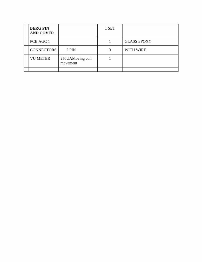
BERG PIN AND COVER
1 SET
PCB AGC 1 1 GLASS EPOXY
CONNECTORS 2 PIN 3 WITH WIRE
VU METER 250UAMoving coil movement
1