ADJ Products, LLC€¦ · ADJ Products, LLC - - 18P Hex User Manual Page 6 ADJ Products, LLC - -...
14
4/17 User Instructions 18P HEX ©2017 ADJ Products, LLC all rights reserved. Information, specifications, diagrams, images, and instructions herein are subject to change without notice. ADJ Products, LLC logo and identifying product names and numbers herein are trademarks of ADJ Products, LLC. Copyright protection claimed includes all forms and matters of copyrightable materials and information now allowed by statutory or judicial law or hereinafter granted. Product names used in this document may be trademarks or registered trademarks of their respective companies and are hereby acknowledged. All non-ADJ Products, LLC brands and product names are trademarks or registered trademarks of their respective companies. ADJ Products, LLC and all affiliated companies hereby dis- claim any and all liabilities for property, equipment, building, and electrical damages, injuries to any persons, and direct or indi- rect economic loss associated with the use or reliance of any information contained within this document, and/or as a result of the improper, unsafe, unsufficient and negligent assembly, installation, rigging, and operation of this product. Europe Energy Saving Notice Energy Saving Matters (EuP 2009/125/EC) Saving electric energy is a key to help protecting the enviroment. Please turn off all electrical products when they are not in use. To avoid power consumption in idle mode, disconnect all electrical equipment from power when not in use. Thank you! 4010765 Date Document Version Software Version DMX Channel Mode Notes > DOCUMENT VERSION Please check www.adj.com for the latest revision/update of this guide. 07/13/17 1 1.00 6/7/8/11/12 Initial Release
Transcript of ADJ Products, LLC€¦ · ADJ Products, LLC - - 18P Hex User Manual Page 6 ADJ Products, LLC - -...
4/17
User Instructions
18P HEX
©2017 ADJ Products, LLC all rights reserved. Information, specifications, diagrams, images, and instructions herein are subject to change without notice. ADJ Products, LLC logo and identifying product names and numbers herein are trademarks of ADJ Products, LLC. Copyright protection claimed includes all forms and matters of copyrightable materials and information now allowed by statutory or judicial law or hereinafter granted. Product names used in this document may be trademarks or registered trademarks of their respective companies and are hereby acknowledged. All non-ADJ Products, LLC brands and product names are trademarks or registered trademarks of their respective companies.ADJ Products, LLC and all affiliated companies hereby dis-claim any and all liabilities for property, equipment, building, and electrical damages, injuries to any persons, and direct or indi-rect economic loss associated with the use or reliance of any information contained within this document, and/or as a result of the improper, unsafe, unsufficient and negligent assembly, installation, rigging, and operation of this product.
Europe Energy Saving NoticeEnergy Saving Matters (EuP 2009/125/EC)Saving electric energy is a key to help protecting the enviroment. Please turn off all electrical products when they are not in use. To avoid power consumption in idle mode, disconnect all electrical equipment from power when not in use. Thank you!4 0 1 0 7 6 5
Date DocumentVersion
SoftwareVersion
DMXChannelMode
Notes>
DOCUMENT VERSIONPlease check www.adj.com for the latest revision/update of this guide.
07/13/17 1 1.00 6/7/8/11/12 Initial Release
18P Hex Introduction
ADJ Products, LLC - www.adj.com - 18P Hex User Manual Page 2
Unpacking: Thank you for purchasing the 18P Hex by ADJ Products, LLC. Every 18P Hex has been thoroughly tested and has been shipped in perfect operating condition. Carefully check the shipping carton for damage that may have occurred during shipping. If the carton appears to be damaged, carefully inspect your fixture for any damage and be sure all accessories necessary to operate the unit has arrived intact. In the case damage has been found or parts are missing, please contact our toll free customer support number for further instructions. Do not return this unit to your dealer without first contacting customer sup-port. Introduction: The 18P Hex is a DMX intelligent, LED par fixture. This fixture can be used in a stand alone mode or connected in a Master/Slave configuration. This par has five operating modes: Sound Active mode, Program mode, RGBWA + UV dimmer mode, Static Color mode, and DMX control mode. The 18P has 4 DMX channel modes; 6, 7, 8, & 12. Customer Support: ADJ Products, LLC provides a customer support line, to provide set up help and to answer any question should you encounter problems during your set up or initial operation. You may also visit us on the web at www.adj.com for any comments or sugges-tions. Service Hours are Monday through Friday 8:00 a.m. to 4:30 p.m. Pacific Standard Time. Voice: (323) 582-2650 Fax: (323) 582-2941 E-mail: [email protected]
Warning! To prevent or reduce the risk of electrical shock or fire, do not expose this unit to rain or moisture.
Caution! There are no user serviceable parts inside this unit. Do not attempt any repairs yourself, doing so will void your manufactures war-ranty. In the unlikely event your unit may require service please contact ADJ Products, LLC.PLEASE recycle the shipping carton when ever possible.
ADJ Products, LLC - www.adj.com - 18P Hex User Manual Page 3
• Multi-Colors• Five Operating Modes• Electronic Dimming 0-100%• 5 Dimmer Curves• Built in Microphone• DMX-512 protocol• 3-Pin DMX Connection• 4 DMX Modes: 6 Channel Mode, 7 Channel Mode, 8 Channel Mode, & 12 Channel Mode.• Dotz Par RF compatiable (Not Included)• Power Cord Daisy Chain (See page 13)
18P Hex Warranty Registration
18P Hex Features
The 18P Hex carries a 2 year limited warranty. Please fill out the enclosed warranty card to validate your purchase. All returned service items whether under warranty or not, must be freight pre-paid and accompany a return authorization (R.A.) number. The R.A. number must be clearly written on the outside of the return package. A brief description of the problem as well as the R.A. number must also be written down on a piece of paper included in the shipping carton. If the unit is under warranty, you must provide a copy of your proof of purchase invoice. You may obtain a R.A. number by contacting our customer support team on our customer support number. All pack-ages returned to the service department not displaying a R.A. number on the outside of the package will be returned to the shipper.
The unit should be mounted using a mounting clamp (not provided), affixing it to the mounting bracket that is provided with the unit. Always ensure that the unit is firmly fixed to avoid vibration and slip-ping while operating. Always ensure that the structure to which you are attaching the unit is secure and is able to support a weight of 10 times the unit’s weight. Also, always use a safety cable that can hold 12 times the weight of the unit when installing the fixture.The equipment must be installed by a professional, and it must be installed in a place where it is out of the reach of people’s grasp.
18P Hex Installation
18P Hex Safety Precautions
ADJ Products, LLC - www.adj.com - 18P Hex User Manual Page 4
• To reduce the risk of electrical shock or fire, do not expose this unit rain or moisture• Do not spill water or other liquids into or on to your unit.• Do not attempt to operate this unit if the power cord has been frayed or broken. Do not attempt to remove or break off the ground prong from the electrical cord. This prong is used to reduce the risk of electrical shock and fire in case of an internal short.• Disconnect from main power before making any type of connection.• Do not remove the cover under any conditions. There are no user serviceable parts inside.• Never operate this unit when it’s cover is removed.• Never plug this unit in to a dimmer pack• Always be sure to mount this unit in an area that will allow proper ventilation. Allow about 6” (15cm) between this device and a wall.• Do not attempt to operate this unit, if it becomes damaged.• This unit is intended for indoor use only, use of this product out` doors voids all warranties.• During long periods of non-use, disconnect the unit’s main power.• Always mount this unit in safe and stable matter.• Power-supply cords should be routed so that they are not likely to be walked on or pinched by items placed upon or against them, paying particular attention to the point they exit from the unit. • Cleaning -The fixture should be cleaned only as recommended by t he manufacturer. See page 22 for cleaning details.• Heat -The appliance should be situated away from heat sources such as radiators, heat registers, stoves, or other appliances (inclu- d ing amplifiers) that produce heat.• The fixture should be serviced by qualified service personnel when: A. The power-supply cord or the plug has been damaged. B. Objects have fallen, or liquid has been spilled into the appliance. C. The appliance has been exposed to rain or water. D. The appliance does not appear to operate normally or exhibits a marked change in performance.
ADJ Products, LLC - www.adj.com - 18P Hex User Manual Page 5
RISK GROUP 3 - RISK OF EXPOSURE TO ULTRAVIOLET (UV) RADIATION!
FIXTURE EMITS HIGH INTENSITY ULTRAVIOLET (UV) LIGHT AT A WAVELENGTH OF 390NM - 410NM.
WEAR PROPER EYE AND SKIN PROTECTION.
AVOID PROLONGED PERIODS OF EXPOSURE.
AVOID WEARING WHITE COLOR CLOTHING AND/OR USING (UV) PAINTS ON SKIN.
AVOID DIRECT EYE AND/OR SKIN EXPOSURE AT DISTANCES SHORTER THAN 11 feet (3.3m).
DO NOT OPERATE FIXTURE WITH DAMAGED OR MISSING EXTERNAL COVER PROTECTIVE LENS.
DO NOT LOOK DIRECTLY INTO THE (UV) LIGHT AND/OR VIEW (UV) LIGHT DIRECTLY WITH OPTICAL INSTRUMENTS THAT MAY CONCEN-TRATE THE LIGHT/RADIATION OUTPUT.
INDIVIDUALS SUFFERING FROM A RANGE OF EYE CONDITIONS, SUN-LIGHT EXPOSURE DISORDERS, OR INDIVIDUALS USING PHOTOSEN-SITIVE MEDICATION, MAY RECEIVE DISCOMFORT IF EXPOSED TO THE ULTRAVIOLET (UV) LIGHT EMITTED FROM THIS FIXTURE.
18P Hex Safety Precautions
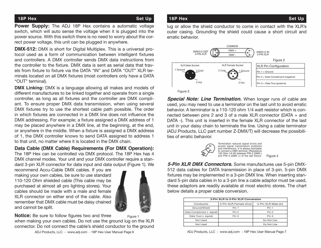
lug or allow the shield conductor to come in contact with the XLR’s outer casing. Grounding the shield could cause a short circuit and erratic behavior.
18P Hex Set Up
DMX512 IN3-PIN XLR
SOUNDREMOTECONTROLINPUT
POWER
INPUT OUTPUTSOUND
REMOTECONTROLINPUT
POWER
INPUT OUTPUTSOUND
REMOTECONTROLINPUT
POWER
INPUT OUTPUT
DMX512DMX+,DMX-,COMMON
1
23
Termination reduces signal errors andavoids signal transmission problemsand interference. It is always advisableto connect a DMX terminal, (Resistance120 Ohm 1/4 W) between PIN 2 (DMX-)and PIN 3 (DMX +) of the last fixture.
1
23
1
23
DMX +
DMX -
COMMON
DMX512 O�T3-PIN XLR
Figure 2
Figure 3
1 Ground 1 Ground
XLR Male Socket XLR Pin Configuration
3 Hot
2 Cold 2 Cold
3 Hot
XLR Female Socket
Pin 3 = Data True (positive)
Pin 2 = Data Compliment (negative)
Pin 1 = Ground
Special Note: Line Termination. When longer runs of cable are used, you may need to use a terminator on the last unit to avoid erratic behavior. A terminator is a 110-120 ohm 1/4 watt resistor which is con-nected between pins 2 and 3 of a male XLR connector (DATA + and DATA -). This unit is inserted in the female XLR connector of the last unit in your daisy chain to terminate the line. Using a cable terminator (ADJ Products, LLC part number Z-DMX/T) will decrease the possibili-ties of erratic behavior.
DMX512 IN3-PIN XLR
SOUNDREMOTECONTROLINPUT
POWER
INPUT OUTPUTSOUND
REMOTECONTROLINPUT
POWER
INPUT OUTPUTSOUND
REMOTECONTROLINPUT
POWER
INPUT OUTPUT
DMX512DMX+,DMX-,COMMON
1
23
Termination reduces signal errors andavoids signal transmission problemsand interference. It is always advisableto connect a DMX terminal, (Resistance120 Ohm 1/4 W) between PIN 2 (DMX-)and PIN 3 (DMX +) of the last fixture.
1
23
1
23
DMX +
DMX -
COMMON
DMX512 O�T3-PIN XLR
Figure 4
5-Pin XLR DMX Connectors. Some manufactures use 5-pin DMX-512 data cables for DATA transmission in place of 3-pin. 5-pin DMX fixtures may be implemented in a 3-pin DMX line. When inserting stan-dard 5-pin data cables in to a 3-pin line a cable adaptor must be used, these adaptors are readily available at most electric stores. The chart below details a proper cable conversion.
Conductor 5-Pin XLR Male (In)3-Pin XLR Female (Out)Pin 1
Do Not Use
Do Not Use
Pin 3
Pin 2
Pin 1
Pin 3
Pin 2
Not Used
Not Used
Data True (+ signal)
Data Compliment (- signal)
Ground/Shield
3-Pin XLR to 5-Pin XLR Conversion
ADJ Products, LLC - www.adj.com - 18P Hex User Manual Page 6 ADJ Products, LLC - www.adj.com - 18P Hex User Manual Page 7
Power Supply: The ADJ 18P Hex contains a automatic voltage switch, which will auto sense the voltage when it is plugged into the power source. With this switch there is no need to worry about the cor-rect power voltage, this unit can be plugged in anywhere. DMX-512: DMX is short for Digital Multiplex. This is a universal pro-tocol used as a form of communication between intelligent fixtures and controllers. A DMX controller sends DMX data instructions from the controller to the fixture. DMX data is sent as serial data that trav-els from fixture to fixture via the DATA “IN” and DATA “OUT” XLR ter-minals located on all DMX fixtures (most controllers only have a DATA “OUT” terminal). DMX Linking: DMX is a language allowing all makes and models of different manufactures to be linked together and operate from a single controller, as long as all fixtures and the controller are DMX compli-ant. To ensure proper DMX data transmission, when using several DMX fixtures try to use the shortest cable path possible. The order in which fixtures are connected in a DMX line does not influence the DMX addressing. For example; a fixture assigned a DMX address of 1 may be placed anywhere in a DMX line, at the beginning, at the end, or anywhere in the middle. When a fixture is assigned a DMX address of 1, the DMX controller knows to send DATA assigned to address 1 to that unit, no matter where it is located in the DMX chain.Data Cable (DMX Cable) Requirements (For DMX Operation): The 18P Hex can be controlled via DMX protocol. The 18P Hex has 4 DMX channel modes. Your unit and your DMX controller require a stan-dard 3-pin XLR connector for data input and data output (Figure 1). We recommend Accu-Cable DMX cables. If you are making your own cables, be sure to use standard 110-120 Ohm shielded cable (This cable may be purchased at almost all pro lighting stores). Your cables should be made with a male and female XLR connector on either end of the cable. Also remember that DMX cable must be daisy chained and cannot be split.
Notice: Be sure to follow figures two and three when making your own cables. Do not use the ground lug on the XLR connector. Do not connect the cable’s shield conductor to the ground
18P Hex Set Up
Figure 1
18P Hex System Menu
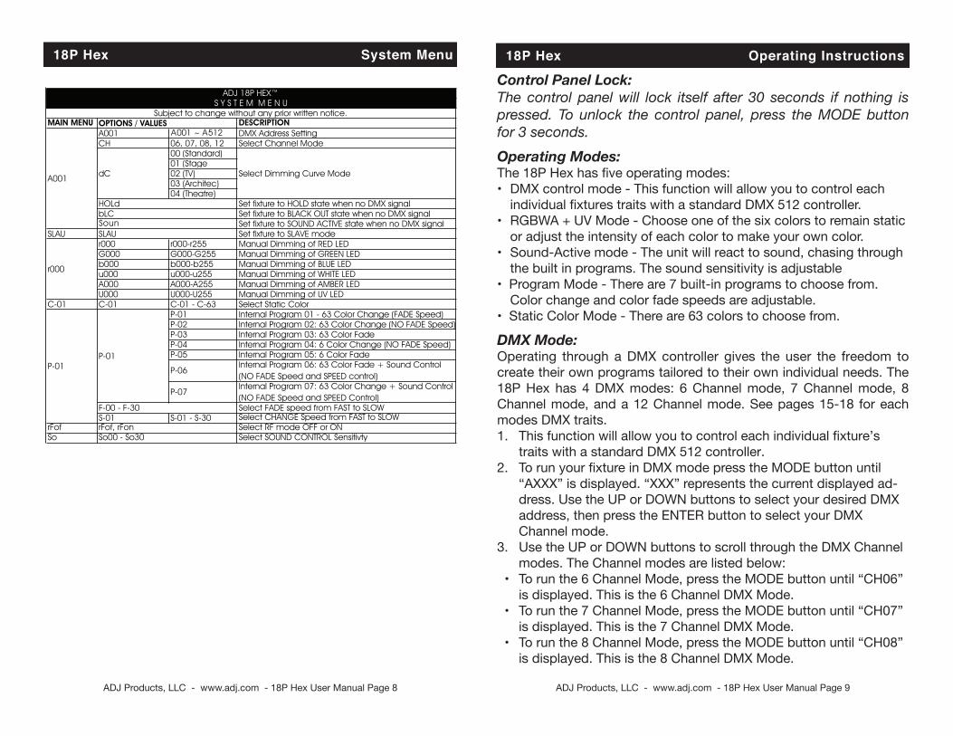
MAIN MENU DESCRIPTIONA001 A001 ~ A512 DMX Address SettingCH 06, 07, 08, 12 Select Channel Mode
00 (Standard)01 (Stage02 (TV)03 (Architec)04 (Theatre)
Set fixture to HOLD state when no DMX signalSet fixture to BLACK OUT state when no DMX signalSet fixture to SOUND ACTIVE state when no DMX signal
SLAU Set fixture to SLAVE moder000 r000-r255 Manual Dimming of RED LEDG000 G000-G255 Manual Dimming of GREEN LEDb000 b000-b255 Manual Dimming of BLUE LEDu000 u000-u255 Manual Dimming of WHITE LEDA000 A000-A255 Manual Dimming of AMBER LEDU000 U000-U255 Manual Dimming of UV LED
C-01 C-01 C-01 - C-63 Select Static ColorP-01 Internal Program 01 - 63 Color Change (FADE Speed)P-02 Internal Program 02: 63 Color Change (NO FADE Speed)P-03 Internal Program 03: 63 Color FadeP-04 Internal Program 04: 6 Color Change (NO FADE Speed)P-05 Internal Program 05: 6 Color Fade
Select FADE speed from FAST to SLOWS-01 S-01 - S-30 Select CHANGE Speed from FAST to SLOW
rFof Select RF mode OFF or ONSo Select SOUND CONTROL Sensitivty
ADJ 18P HEX™S Y S T E M M E N U
Subject to change without any prior written notice.
dC Select Dimming Curve Mode
OPTIONS / VALUES
A001
r000
rFof, rFonSo00 - So30
P-01
F-00 - F-30
P-06
HOLd
Internal Program 06: 63 Color Fade + Sound Control(NO FADE Speed and SPEED control)
P-01
P-07
bLCSoun
Internal Program 07: 63 Color Change + Sound Control(NO FADE Speed and SPEED Control)
SLAU
ADJ Products, LLC - www.adj.com - 18P Hex User Manual Page 8
18P Hex Operating Instructions
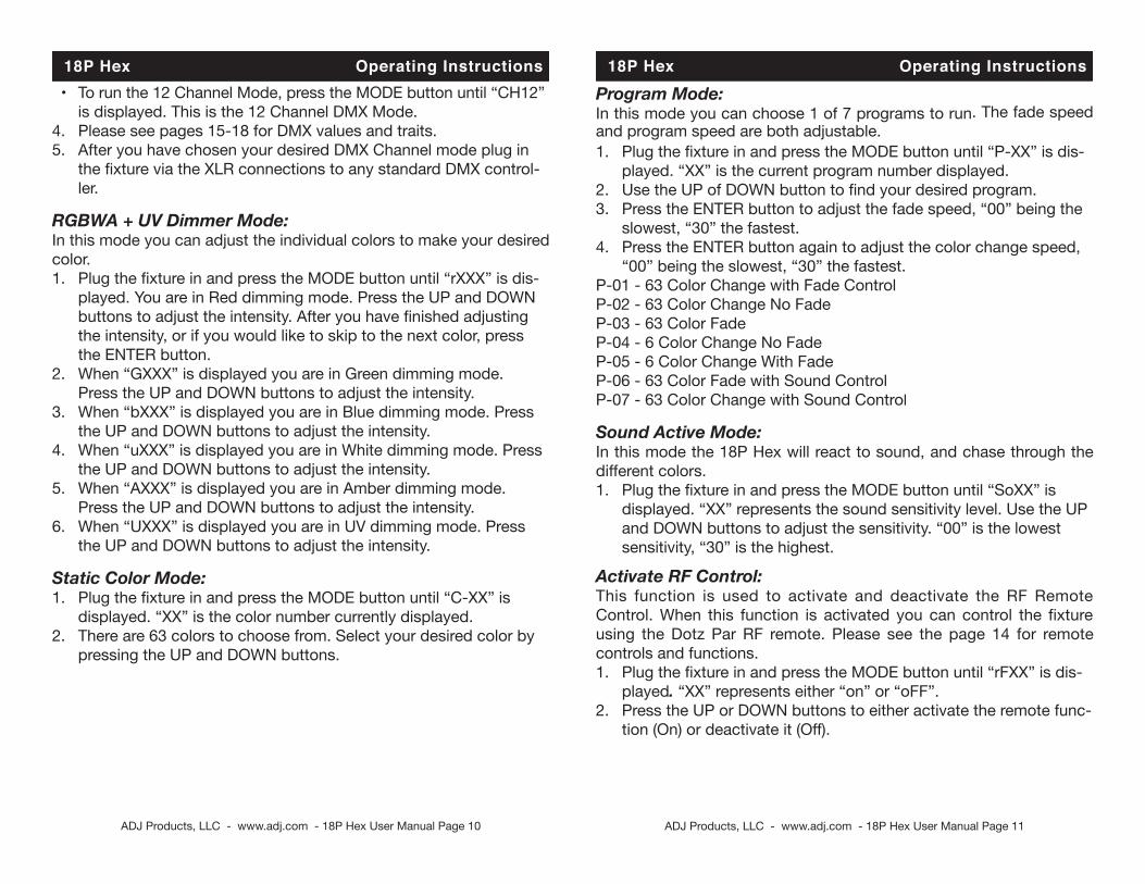
Control Panel Lock:The control panel will lock itself after 30 seconds if nothing is pressed. To unlock the control panel, press the MODE button for 3 seconds.Operating Modes:The 18P Hex has five operating modes:• DMX control mode - This function will allow you to control each individual fixtures traits with a standard DMX 512 controller. • RGBWA + UV Mode - Choose one of the six colors to remain static or adjust the intensity of each color to make your own color. • Sound-Active mode - The unit will react to sound, chasing through the built in programs. The sound sensitivity is adjustable• Program Mode - There are 7 built-in programs to choose from. Color change and color fade speeds are adjustable.• Static Color Mode - There are 63 colors to choose from.
DMX Mode:Operating through a DMX controller gives the user the freedom to create their own programs tailored to their own individual needs. The 18P Hex has 4 DMX modes: 6 Channel mode, 7 Channel mode, 8 Channel mode, and a 12 Channel mode. See pages 15-18 for each modes DMX traits.1. This function will allow you to control each individual fixture’s traits with a standard DMX 512 controller.2. To run your fixture in DMX mode press the MODE button until “AXXX” is displayed. “XXX” represents the current displayed ad- dress. Use the UP or DOWN buttons to select your desired DMX address, then press the ENTER button to select your DMX Channel mode. 3. Use the UP or DOWN buttons to scroll through the DMX Channel modes. The Channel modes are listed below: • To run the 6 Channel Mode, press the MODE button until “CH06” is displayed. This is the 6 Channel DMX Mode. • To run the 7 Channel Mode, press the MODE button until “CH07” is displayed. This is the 7 Channel DMX Mode. • To run the 8 Channel Mode, press the MODE button until “CH08” is displayed. This is the 8 Channel DMX Mode.
ADJ Products, LLC - www.adj.com - 18P Hex User Manual Page 9
ADJ Products, LLC - www.adj.com - 18P Hex User Manual Page 10
18P Hex Operating InstructionsProgram Mode: In this mode you can choose 1 of 7 programs to run. The fade speed and program speed are both adjustable.1. Plug the fixture in and press the MODE button until “P-XX” is dis- played. “XX” is the current program number displayed.2. Use the UP of DOWN button to find your desired program.3. Press the ENTER button to adjust the fade speed, “00” being the slowest, “30” the fastest.4. Press the ENTER button again to adjust the color change speed, “00” being the slowest, “30” the fastest.P-01 - 63 Color Change with Fade ControlP-02 - 63 Color Change No FadeP-03 - 63 Color FadeP-04 - 6 Color Change No FadeP-05 - 6 Color Change With FadeP-06 - 63 Color Fade with Sound ControlP-07 - 63 Color Change with Sound Control
Sound Active Mode:In this mode the 18P Hex will react to sound, and chase through the different colors.1. Plug the fixture in and press the MODE button until “SoXX” is displayed. “XX” represents the sound sensitivity level. Use the UP and DOWN buttons to adjust the sensitivity. “00” is the lowest sensitivity, “30” is the highest.
Activate RF Control:This function is used to activate and deactivate the RF Remote Control. When this function is activated you can control the fixture using the Dotz Par RF remote. Please see the page 14 for remote controls and functions.1. Plug the fixture in and press the MODE button until “rFXX” is dis- played. “XX” represents either “on” or “oFF”.2. Press the UP or DOWN buttons to either activate the remote func- tion (On) or deactivate it (Off).
ADJ Products, LLC - www.adj.com - 18P Hex User Manual Page 11
18P Hex Operating Instructions • To run the 12 Channel Mode, press the MODE button until “CH12” is displayed. This is the 12 Channel DMX Mode.4. Please see pages 15-18 for DMX values and traits.5. After you have chosen your desired DMX Channel mode plug in the fixture via the XLR connections to any standard DMX control- ler.
RGBWA + UV Dimmer Mode:In this mode you can adjust the individual colors to make your desired color.1. Plug the fixture in and press the MODE button until “rXXX” is dis- played. You are in Red dimming mode. Press the UP and DOWN buttons to adjust the intensity. After you have finished adjusting the intensity, or if you would like to skip to the next color, press the ENTER button.2. When “GXXX” is displayed you are in Green dimming mode. Press the UP and DOWN buttons to adjust the intensity.3. When “bXXX” is displayed you are in Blue dimming mode. Press the UP and DOWN buttons to adjust the intensity.4. When “uXXX” is displayed you are in White dimming mode. Press the UP and DOWN buttons to adjust the intensity.5. When “AXXX” is displayed you are in Amber dimming mode. Press the UP and DOWN buttons to adjust the intensity.6. When “UXXX” is displayed you are in UV dimming mode. Press the UP and DOWN buttons to adjust the intensity.
Static Color Mode:1. Plug the fixture in and press the MODE button until “C-XX” is displayed. “XX” is the color number currently displayed.2. There are 63 colors to choose from. Select your desired color by pressing the UP and DOWN buttons.
18P Hex Operating Instructions
Dimmer Curve:This is used to set the dimmer curve used with DMX mode. See the Dimmer Curve chart on page 20 for more information.1. Plug the fixture in and press the MODE button until the DMX address is displayed.2. Press the ENTER button until “dCXX” is displayed. This is the dimmer setting. “XX” represents the current dimming mode.3. Use the UP and DOWN buttons to find your desired dimmer curve. Press SET UP when you are finished. • dC00 - Standard • dC01 - Stage • dC02 - TV • dC03 - Architectural • dC04 - Theater
DMX State:This mode is used as a precaution mode, that in case the DMX signal is lost, the operating mode chosen in this setup is the running mode the fixture will go into when the DMX signal is lost. You can also set this as the operating mode you would like the unit to return to when power is applied. 1. Press the MODE button until the DMX address is displayed. Press the ENTER button until either “Soun”, “HOLd”, or “bLC” is dis- played.2. Use the UP or DOWN buttons to find the mode you want incase of power loss or DMX loss.• “bLC” (Blackout) - If the DMX signal is lost or interrupted, the unit will automatically go into stand by mode.• “HOLd” (Last State) - If the DMX signal is lost or interrupted, the fix-ture will stay in the last DMX set up. If power is applied and this mode is set, the unit will automatically go into the last DMX set up. • “Soun” (Sound Active) - If the DMX signal is lost or interrupted, the unit will automatically go into sound active mode.3. Find your desired setting and press ENTER. Your setting will be saved automatically.
ADJ Products, LLC - www.adj.com - 18P Hex User Manual Page 12
Master-Slave Configuration: This function will allows you to link units together to run in a Master-Slave mode. In Master-Slave operation one unit will act as the con-trolling unit and the others will react to the controlling units built-in programs. Any unit can act as a Master or as a Slave however, only one unit can be programmed to act as the “Master.” Master-Slave Connections and Settings:1. Daisy chain your units via the XLR connector on the rear of the unit. Use standard XLR data cables to link your units together. Remember that the Male XLR connector is the input and the Female XLR connector is the ouput. The first unit in the chain (master) will use the female XLR connector only. The last unit in the chain will use the male XLR connector only. 2. Set the “Master” unit to your desired mode of operation. 3. Connect the first “Slave” unit to the “Master.”4. On the “Slave” unit press the MODE button until “SLAv” is dis- played. The “Slave” unit will now follow the “Master”.
18P Hex Master-Slave Configuration
With this feature you can connect the fixtures to one another using the powerCON input and output sockets. The quantity that can be connected is 4 fixtures maximum for 120V and 8 fixtures maximum for 240V. After the maximum fixtures has been reached you will need to use a new power outlet. NOTE: USE CAUTION WHEN POWER LINKING OTHER FIXTURES TO THE 18P HEX. POWER CONSUMPTION OF OTHER LIGHTING FIXTURES WILL VARY. ALWAYS CHECK THE MAX AMP OUT RATING OF EACH FIXTURE!
18P Hex Power Cord Daisy Chain
ADJ Products, LLC - www.adj.com - 18P Hex User Manual Page 13
ADJ Products, LLC - www.adj.com - 18P Hex User Manual Page 14
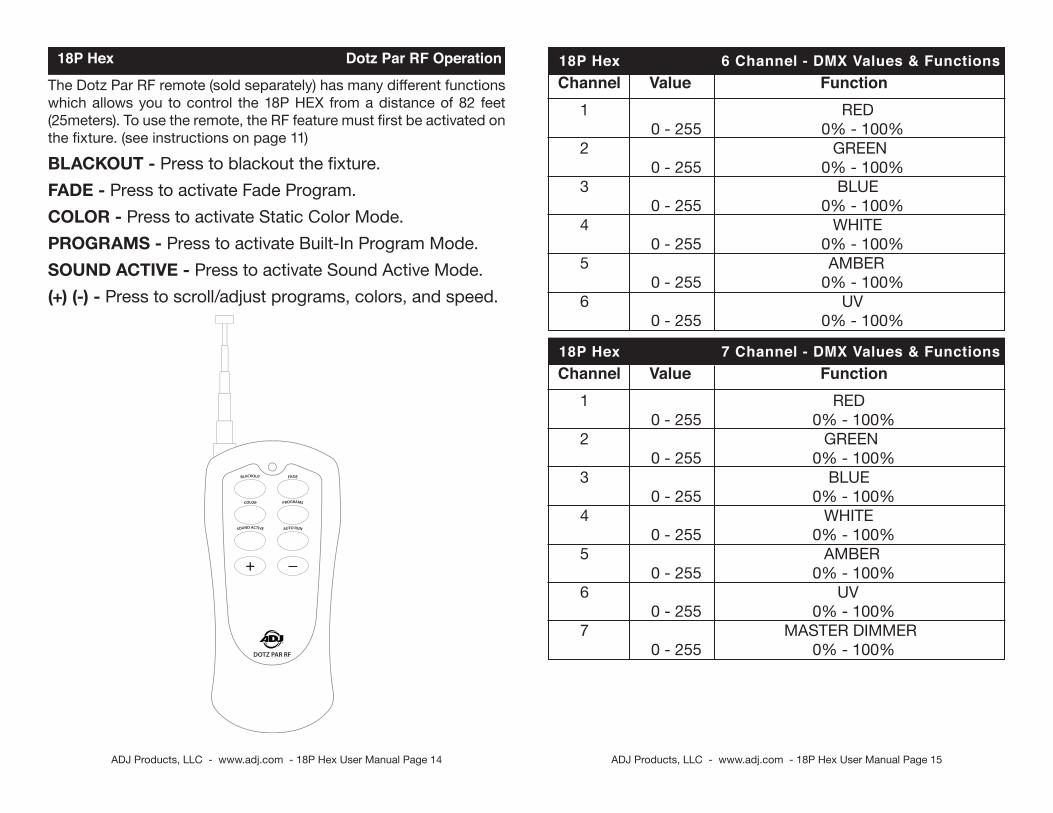
Channel Value Function 1 RED 0 - 255 0% - 100% 2 GREEN 0 - 255 0% - 100% 3 BLUE 0 - 255 0% - 100% 4 WHITE 0 - 255 0% - 100% 5 AMBER 0 - 255 0% - 100% 6 UV 0 - 255 0% - 100%
18P Hex 6 Channel - DMX Values & Functions
Channel Value Function 1 RED 0 - 255 0% - 100% 2 GREEN 0 - 255 0% - 100% 3 BLUE 0 - 255 0% - 100% 4 WHITE 0 - 255 0% - 100% 5 AMBER 0 - 255 0% - 100% 6 UV 0 - 255 0% - 100% 7 MASTER DIMMER 0 - 255 0% - 100%
18P Hex 7 Channel - DMX Values & Functions
ADJ Products, LLC - www.adj.com - 18P Hex User Manual Page 15
18P Hex Dotz Par RF Operation
The Dotz Par RF remote (sold separately) has many different functions which allows you to control the 18P HEX from a distance of 82 feet (25meters). To use the remote, the RF feature must first be activated on the fixture. (see instructions on page 11)
BLACKOUT - Press to blackout the fixture.FADE - Press to activate Fade Program.COLOR - Press to activate Static Color Mode.PROGRAMS - Press to activate Built-In Program Mode.SOUND ACTIVE - Press to activate Sound Active Mode.(+) (-) - Press to scroll/adjust programs, colors, and speed.
ADJ Products, LLC - www.adj.com - 18P Hex User Manual Page 16
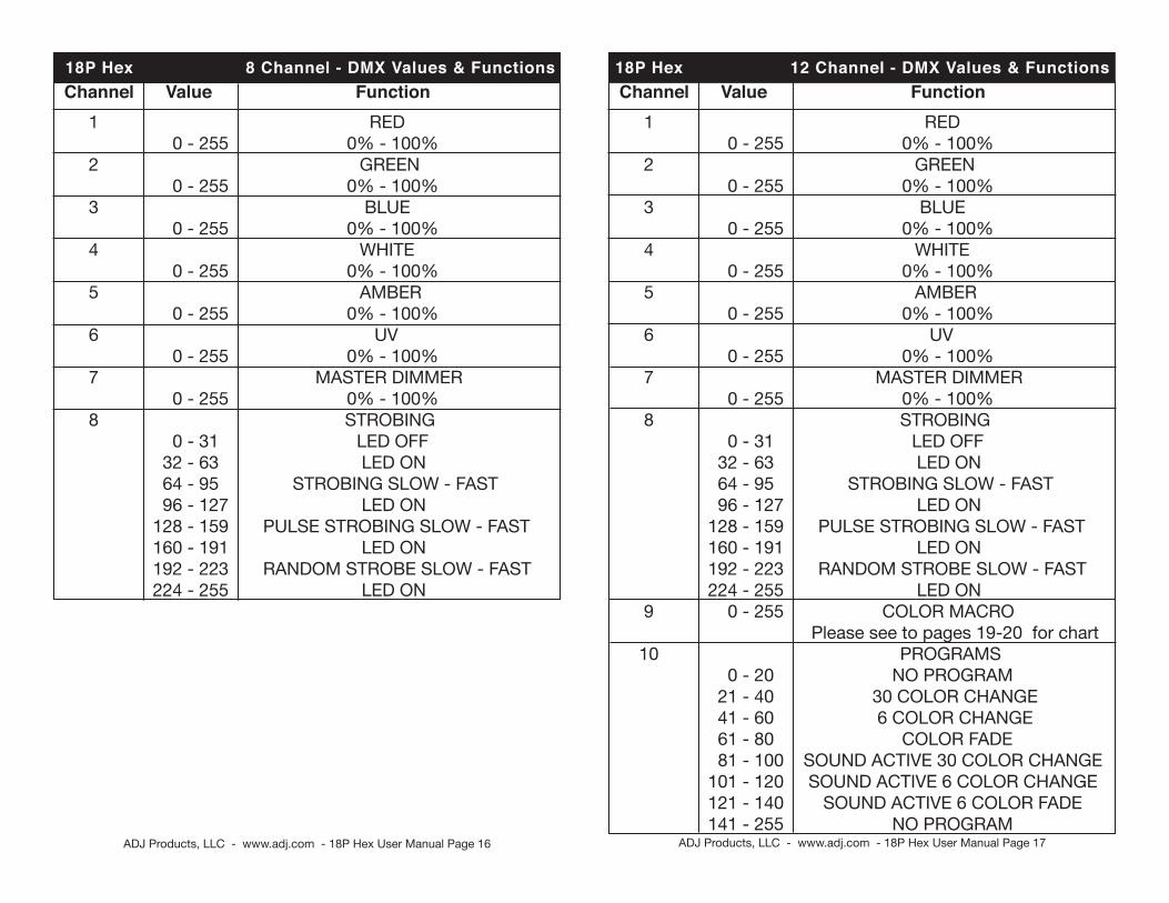
18P Hex 12 Channel - DMX Values & Functions Channel Value Function 1 RED 0 - 255 0% - 100% 2 GREEN 0 - 255 0% - 100% 3 BLUE 0 - 255 0% - 100% 4 WHITE 0 - 255 0% - 100% 5 AMBER 0 - 255 0% - 100% 6 UV 0 - 255 0% - 100% 7 MASTER DIMMER 0 - 255 0% - 100% 8 STROBING 0 - 31 LED OFF 32 - 63 LED ON 64 - 95 STROBING SLOW - FAST 96 - 127 LED ON 128 - 159 PULSE STROBING SLOW - FAST 160 - 191 LED ON 192 - 223 RANDOM STROBE SLOW - FAST 224 - 255 LED ON 9 0 - 255 COLOR MACRO Please see to pages 19-20 for chart 10 PROGRAMS 0 - 20 NO PROGRAM 21 - 40 30 COLOR CHANGE 41 - 60 6 COLOR CHANGE 61 - 80 COLOR FADE 81 - 100 SOUND ACTIVE 30 COLOR CHANGE 101 - 120 SOUND ACTIVE 6 COLOR CHANGE 121 - 140 SOUND ACTIVE 6 COLOR FADE 141 - 255 NO PROGRAM
Channel Value Function 1 RED 0 - 255 0% - 100% 2 GREEN 0 - 255 0% - 100% 3 BLUE 0 - 255 0% - 100% 4 WHITE 0 - 255 0% - 100% 5 AMBER 0 - 255 0% - 100% 6 UV 0 - 255 0% - 100% 7 MASTER DIMMER 0 - 255 0% - 100% 8 STROBING 0 - 31 LED OFF 32 - 63 LED ON 64 - 95 STROBING SLOW - FAST 96 - 127 LED ON 128 - 159 PULSE STROBING SLOW - FAST 160 - 191 LED ON 192 - 223 RANDOM STROBE SLOW - FAST 224 - 255 LED ON
18P Hex 8 Channel - DMX Values & Functions
ADJ Products, LLC - www.adj.com - 18P Hex User Manual Page 17
ADJ Products, LLC - www.adj.com - 18P Hex User Manual Page 18
18P Hex Color Macro Chart
Color No. DMX VALUE
RGBWA+UV COLOR INTENSITY RED GREEN BLUE WHITE
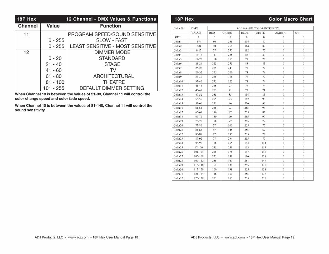
OFF 0 0 0 0 0 Color1 1-4 80 255 234 80 Color2 5-8 80 255 164 80 Color3 9-12 77 255 112 77 Color4 13-16 117 255 83 83 Color5 17-20 160 255 77 77 Color6 21-24 223 255 83 83 Color7 25-28 255 243 77 77 Color8 29-32 255 200 74 74 Color9 33-36 255 166 77 77 Color10 37-40 255 125 74 74 Color11 41-44 255 97 77 74 Color12 45-48 255 71 77 71 Color13 49-52 255 83 134 83 Color14 53-56 255 93 182 93 Color15 57-60 255 96 236 96 Color16 61-64 238 93 255 93 Color17 65-68 196 87 255 87 Color18 69-72 150 90 255 90 Color19 73-76 100 77 255 77 Color20 77-80 77 100 255 77 Color21 81-84 67 148 255 67 Color22 85-88 77 195 255 77 Color23 89-92 77 234 255 77 Color24 93-96 158 255 144 144 Color25 97-100 255 251 153 153 Color26 101-104 255 175 147 147 Color27 105-108 255 138 186 138 Color28 109-112 255 147 251 147 Color29 113-116 151 138 255 138 Color30 117-120 100 138 255 138 Color31 121-124 138 169 255 138 Color32 125-128 255 255 255 255
Color No. DMX VALUE RED GREEN BLUE WHITE
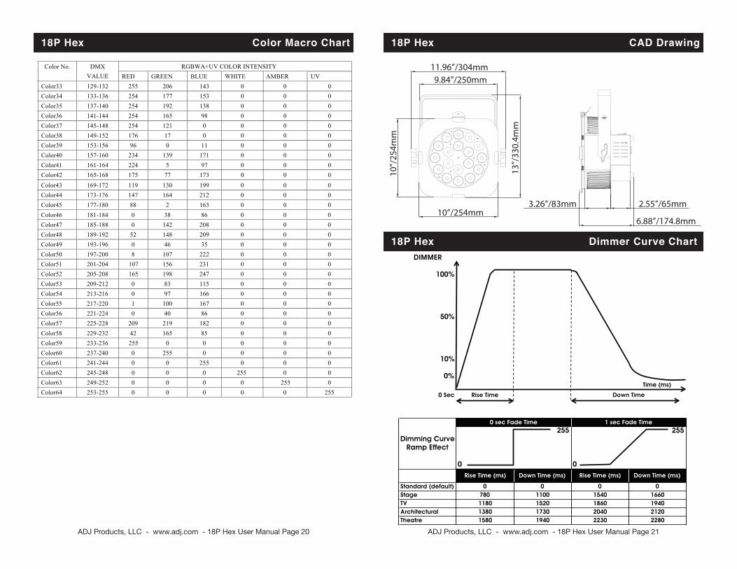
Color33 129-132 255 206 143 0 Color34 133-136 254 177 153 0 Color35 137-140 254 192 138 0 Color36 141-144 254 165 98 0 Color37 145-148 254 121 0 0 Color38 149-152 176 17 0 0 Color39 153-156 96 0 11 0 Color40 157-160 234 139 171 0 Color41 161-164 224 5 97 0 Color42 165-168 175 77 173 0 Color43 169-172 119 130 199 0 Color44 173-176 147 164 212 0 Color45 177-180 88 2 163 0 Color46 181-184 0 38 86 0 Color47 185-188 0 142 208 0 Color48 189-192 52 148 209 0 Color49 193-196 0 46 35 0 Color50 197-200 8 107 222 0 Color51 201-204 107 156 231 0 Color52 205-208 165 198 247 0 Color53 209-212 0 83 115 0 Color54 213-216 0 97 166 0 Color55 217-220 1 100 167 0 Color56 221-224 0 40 86 0 Color57 225-228 209 219 182 0 Color58 229-232 42 165 85 0 Color59 233-236 255 0 0 0 Color60 237-240 0 255 0 0 Color61 241-244 0 0 255 0 Color62 245-248 0 0 0 255 Color63 249-252 0 0 0 0 Color64 253-255 0 0 0 0
0 0 0 0 0 0 0 0 0 0 0 0 0 0 0 0 0 0 0 0 0 0 0 0
0 0 0 0 0 0 0 0 0
0 0 0 0 0 0 0 0 0 0 0 0 0 0 0 0 0 0 0 0 0 0 0 0
0 0 0 0 0 0 0 0 0
AMBER UV RGBWA+UV COLOR INTENSITY
0 0 0 0 0 0 0 0 0 0 0 0 0 0 0 0 0 0 0 0 0 0 0 0
0 0 0 0 0 0 0 255
0 0 0 0 0 0 0 0 0 0 0 0 0 0 0 0 0 0 0 0 0 0 0 0
0 0 0 0 0 0 255 0
AMBER UV
ADJ Products, LLC - www.adj.com - 18P Hex User Manual Page 19
18P Hex 12 Channel - DMX Values & Functions Channel Value Function 11 PROGRAM SPEED/SOUND SENSITIVE 0 - 255 SLOW - FAST 0 - 255 LEAST SENSITIVE - MOST SENSITIVE 12 DIMMER MODE 0 - 20 STANDARD 21 - 40 STAGE 41 - 60 TV 61 - 80 ARCHITECTURAL 81 - 100 THEATRE 101 - 255 DEFAULT DIMMER SETTING When Channel 10 is between the values of 21-80, Channel 11 will control the color change speed and color fade speed.
When Channel 10 is between the values of 81-140, Channel 11 will control the sound sensitivity.
Color No. DMX VALUE
RGBWA+UV COLOR INTENSITY RED GREEN BLUE WHITE
OFF 0 0 0 0 0 Color1 1-4 80 255 234 80 Color2 5-8 80 255 164 80 Color3 9-12 77 255 112 77 Color4 13-16 117 255 83 83 Color5 17-20 160 255 77 77 Color6 21-24 223 255 83 83 Color7 25-28 255 243 77 77 Color8 29-32 255 200 74 74 Color9 33-36 255 166 77 77 Color10 37-40 255 125 74 74 Color11 41-44 255 97 77 74 Color12 45-48 255 71 77 71 Color13 49-52 255 83 134 83 Color14 53-56 255 93 182 93 Color15 57-60 255 96 236 96 Color16 61-64 238 93 255 93 Color17 65-68 196 87 255 87 Color18 69-72 150 90 255 90 Color19 73-76 100 77 255 77 Color20 77-80 77 100 255 77 Color21 81-84 67 148 255 67 Color22 85-88 77 195 255 77 Color23 89-92 77 234 255 77 Color24 93-96 158 255 144 144 Color25 97-100 255 251 153 153 Color26 101-104 255 175 147 147 Color27 105-108 255 138 186 138 Color28 109-112 255 147 251 147 Color29 113-116 151 138 255 138 Color30 117-120 100 138 255 138 Color31 121-124 138 169 255 138 Color32 125-128 255 255 255 255
Color No. DMX VALUE RED GREEN BLUE WHITE
Color33 129-132 255 206 143 0 Color34 133-136 254 177 153 0 Color35 137-140 254 192 138 0 Color36 141-144 254 165 98 0 Color37 145-148 254 121 0 0 Color38 149-152 176 17 0 0 Color39 153-156 96 0 11 0 Color40 157-160 234 139 171 0 Color41 161-164 224 5 97 0 Color42 165-168 175 77 173 0 Color43 169-172 119 130 199 0 Color44 173-176 147 164 212 0 Color45 177-180 88 2 163 0 Color46 181-184 0 38 86 0 Color47 185-188 0 142 208 0 Color48 189-192 52 148 209 0 Color49 193-196 0 46 35 0 Color50 197-200 8 107 222 0 Color51 201-204 107 156 231 0 Color52 205-208 165 198 247 0 Color53 209-212 0 83 115 0 Color54 213-216 0 97 166 0 Color55 217-220 1 100 167 0 Color56 221-224 0 40 86 0 Color57 225-228 209 219 182 0 Color58 229-232 42 165 85 0 Color59 233-236 255 0 0 0 Color60 237-240 0 255 0 0 Color61 241-244 0 0 255 0 Color62 245-248 0 0 0 255 Color63 249-252 0 0 0 0 Color64 253-255 0 0 0 0
0 0 0 0 0 0 0 0 0 0 0 0 0 0 0 0 0 0 0 0 0 0 0 0
0 0 0 0 0 0 0 0 0
0 0 0 0 0 0 0 0 0 0 0 0 0 0 0 0 0 0 0 0 0 0 0 0
0 0 0 0 0 0 0 0 0
AMBER UV RGBWA+UV COLOR INTENSITY
0 0 0 0 0 0 0 0 0 0 0 0 0 0 0 0 0 0 0 0 0 0 0 0
0 0 0 0 0 0 0 255
0 0 0 0 0 0 0 0 0 0 0 0 0 0 0 0 0 0 0 0 0 0 0 0
0 0 0 0 0 0 255 0
AMBER UV
18P Hex Color Macro Chart
ADJ Products, LLC - www.adj.com - 18P Hex User Manual Page 20
18P Hex CAD Drawing
11.96”/304mm 9.84”/250mm
10”/
254m
m
10”/254mm
13”/
330.
4mm
3.26”/83mm 2.55”/65mm
6.88”/174.8mm
18P Hex Dimmer Curve ChartDIMMER
100%
50%
10%
0%Time (ms)
0 Sec
255 255
0 0
Standard (default) 0 0 0 0Stage 780 1100 1540 1660TV 1180 1520 1860 1940Architectural 1380 1730 2040 2120Theatre 1580 1940 2230 2280
Dimming CurveRamp Effect
Rise Time Down Time
0 sec Fade Time 1 sec Fade Time
Rise Time (ms) Down Time (ms) Rise Time (ms) Down Time (ms)
ADJ Products, LLC - www.adj.com - 18P Hex User Manual Page 21
ADJ Products, LLC - www.adj.com - 18P Hex User Manual Page 22
18P Hex Warranty MANUFACTURER’S LIMITED WARRANTYA. ADJ Products, LLC hereby warrants, to the original purchaser, ADJ Products, LLC products to be free of manufacturing defects in material and workmanship for a prescribed period from the date of purchase (see specific warranty period on reverse). This warranty shall be valid only if the product is purchased within the United States of America, including possessions and territories. It is the owner’s responsibility to establish the date and place of purchase by acceptable evidence, at the time service is sought.
B. Fo r war ran ty s e rv i ce you mus t ob t a in a Re tu rn Au tho r i za t i on number (RA#) before sending back the product–please contact ADJ Products, LLC Service Department a t 800-322-6337. Send the product only to the ADJ Products , LLC factory. Al l shipping charges must be pre-paid. If the requested repairs or service ( including parts replacement) are within the terms of this warranty, ADJ Products, LLC will pay return shipping charges only to a designated point within the United States. If the entire instrument is sent, it must be shipped in it’s original package. No accessories should be shipped with the product. If any accessories are shipped with the product, ADJ Products, LLC shall have no liability whatsoever for loss of or damage to any such accessories, nor for the safe return thereof.
C. This warranty is void if the serial number has been altered or removed; if the product is modified in any manner which ADJ Products, LLC concludes, after inspection, affects the reliability of the product; if the product has been repaired or serviced by anyone other than the ADJ Products, LLC factory unless prior written authorization was issued to purchaser by ADJ Products, LLC; if the product is damaged because not properly maintained as set forth in the instruction manual.
D. This is not a service contract, and this warranty does not include maintnance, cleaning or periodic check up. During the period specified above, ADJ Products, LLC will replace defective parts at its expense with new or refurbished parts, and will absorb all expenses for warranty service and repair labor by reason of defects in material or workmanship. The sole responsibility of ADJ Products, LLC under this warranty shall be limited to the repair of the product, or replacement thereof, including parts, at the sole discretion of ADJ Products, LLC. All products covered by this warranty were manufactured after August 15, 2012, and bear indentifying marks to that effect.
E. ADJ Products, LLC reserves the right to make changes in design and/or improvements upon its products without any obligation to include these changes in any products theretofore manufactured.
No warranty, whether expressed or implied, is given or made with respect to any accessory supplied with products described above. Except to the extent prohibited by applicable law, all implied warranties made by ADJ Products, LLC in connection with this product, including warranties of merchantability or fitness, are limited in duration to the warranty period set forth above. And no warranties, whether expressed or implied, including warranties of merchantability or fitness, shall apply to this product after said period has expired. The consumer’s and/or Dealer’s sole remedy shall be such repair or replacement as is expressly provided above; and under no circumstances shall ADJ Products, LLC be liable for any loss or damage, direct or consequential, arising out of the use of, or inability to use, this product.
This warranty is the only written warranty applicable to ADJ Products, LLC Products and supersedes all prior warranties and written descriptions of warranty terms and conditions heretofore published. MANUFACTURER’S LIMITED WARRANTY PERIODS: •NonL.E.D.LightingProducts=1-year(365days)LimitedWarranty(Such as: Special Effect
Lighting, Intelligent Lighting, UV lighting, Strobes, Fog Machines, Bubble Machines, Mirror Balls, Par Cans, Trussing, Lighting Stands etc. excluding LED and lamps)
•LaserProducts=1Year(365Days)LimitedWarranty(excluding laser diodes which have a 6 month limited warranty)
•L.E.D.Products=2-year(730days)LimitedWarranty(excluding batteries which have a 180 day lim-ited warranty). Note:2YearWarrantyonlyappliestopurchaseswithintheUnitedStates.
•StarTecSeries=1YearLimitedWarranty(excluding batteries which have a 180 day limited warranty). •ADJDMXControllers=2Year(730Days)LimitedWarranty
ADJ Products, LLC - www.adj.com - 18P Hex User Manual Page 23
18P Hex Trouble ShootingListed below are a few common problems the user may encounter, with solutions.Unit not responding to DMX:1. Check that the DMX cables are connected properly and are wired correctly (pin 3 is “hot”; on some other DMX devices pin 2 may be ‘hot’). Also, check that all cables are connected to the right connectors; it does matter which way the inputs and outputs are connected.Unit does not respond to sound:1. Quiet or high pitched sounds will not activate the unit.2. Make sure that Sound Active mode is activated.
18P Hex CleaningDue to fog residue, smoke, and dust cleaning the internal and exter-nal optical lenses must be carried out periodically to optimize light output. 1. Use normal glass cleaner and a soft cloth to wipe down the outside casing.2. Clean the external optics with glass cleaner and a soft cloth every 20 days.3. Always be sure to dry all parts completely before plugging the unit back in.Cleaning frequency depends on the environment in which the fixture operates (i.e. smoke, fog residue, dust, dew).
Disconnect the unit from its power source. Remove the power cord from the unit. Once the cord has been removed, use a flat head screw-driver to unscrew the fuse holder. Once unscrewed remove the fuse holder and replace the bad fuse with new fuse. Replace the fuse holder and screw the holder so that it is secure.
18P Hex Fuse Replacement
ADJ Products, LLC - www.adj.com - 18P Hex User Manual Page 24 ADJ Products, LLC - www.adj.com - 18P Hex User Manual Page 25
18P Hex Notes 18P Hex Notes
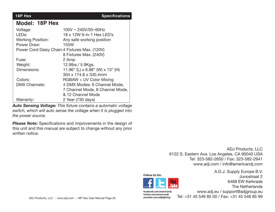
18P Hex Specifications
Model: 18P Hex Voltage: 100V ~ 240V/50~60Hz LEDs: 18 x 12W 6-in-1 Hex LED’s Working Position: Any safe working position Power Draw: 155W Power Cord Daisy Chain: 4 Fixtures Max. (120V) 8 Fixtures Max. (240V) Fuse: 2 Amp Weight: 12.9lbs./ 5.9Kgs. Dimensions: 11.96” (L) x 6.88” (W) x 13” (H) 304 x 174.8 x 330.4mm Colors: RGBAW + UV Color Mixing DMX Channels: 4 DMX Modes: 6 Channel Mode, 7 Channel Mode, 8 Channel Mode, & 12 Channel Mode Warranty: 2 Year (730 days)
Please Note: Specifications and improvements in the design of this unit and this manual are subject to change without any prior written notice.
Auto Sensing Voltage: This fixture contains a automatic voltage switch, which will auto sense the voltage when it is plugged into the power source.
ADJ Products, LLC - www.adj.com - 18P Hex User Manual Page 26
ADJ Products, LLC6122 S. Eastern Ave. Los Angeles, CA 90040 USA
Tel: 323-582-2650 / Fax: 323-582-2941www.adj.com / [email protected]
A.D.J. Supply Europe B.V.Junostraat 2
6468 EW KerkradeThe Netherlands
www.adj.eu / [email protected]: +31 45 546 85 00 / Fax: +31 45 546 85 99