Adikavi Nannaya Universitynannayauniversity.info/links/academic affairs/CBCS 6SEM...
25
1 Adikavi Nannaya University B.Sc. Electronics CBCS SYLLABUS w.e.from 2015-16 admitted batch 3 rd YEAR VI SEMESTER PAPER-VII ELECTIVE (Choose A or B) A: MICRO CONTROLLER AND INTERFACING Practical B: PC MAINTAINANCE AND TROUBLE SHOOTING Practical Paper VIII Cluster Elective A A1: EMBEDDED SYSTEMS DESIGN Practical/Project Work A2: ANALOG AND DIGITAL COMMUNICATIONS Practical A3: POWER ELECTRONICS Practical Cluster Elective (B) B1 COMPUTER NETWORKS Practical B2 ELECTRONIC INSTRUMENTATION Practical B3 OPTICAL FIBER COMMUNICATION AND IT’S APPLICATION Practical
Transcript of Adikavi Nannaya Universitynannayauniversity.info/links/academic affairs/CBCS 6SEM...

1
Adikavi Nannaya University
B.Sc. Electronics CBCS SYLLABUS w.e.from 2015-16 admitted batch
3rd YEAR
VI SEMESTER
PAPER-VII ELECTIVE (Choose A or B) A: MICRO CONTROLLER AND INTERFACING
Practical
B: PC MAINTAINANCE AND TROUBLE SHOOTING
Practical
Paper VIII Cluster Elective A
A1: EMBEDDED SYSTEMS DESIGN
Practical/Project Work
A2: ANALOG AND DIGITAL COMMUNICATIONS
Practical
A3: POWER ELECTRONICS
Practical
Cluster Elective (B)
B1 COMPUTER NETWORKS
Practical
B2 ELECTRONIC INSTRUMENTATION
Practical
B3 OPTICAL FIBER COMMUNICATION AND IT’S
APPLICATION
Practical

2
VI SEMESTER
ELECTIVE PAPER
VII (A): MICRO CONTROLLER AND INTERFACING
OBJECTIVES:
• To understand the concepts of microcontroller based system.
• To enable design and programming of microcontroller based system.
• To know about the interfacing Circuits.
UNIT-I: (10Hrs)
Introduction, comparison of Microprocessor and micro controller, Evolution of
microcontrollers from 4-bit to 32 bit , Development tools for micro controllers,
Assembler-Compiler-Simulator/Debugger.
UNIT -II: (10Hrs)
Microcontroller Architecture:
Block diagram of 8051, Architecture of 8051, program counter and memory organization,
Data types and directives, PSW register, Register banks and stack, pin diagram of 8051,
Interrupts.
UNIT-III:(10Hrs)
Addressing modes, instruction set of 8051: Addressing modes and accessing memory
using various addressing modes, instruction set: Arithmetic, Logical, Simple bit, jump,
loop and call instructions and their usage. Timer/Counter Programming,
Unit -IV: (15Hrs)
Assemble language programming Examples: Addition, Multiplication, Subtraction,
division, arranging a given set of numbers in largest/smallest order.
UNIT-V : (15Hrs)
Interfacing and Application of Microcontroller:
Interfacing of – PPI 8255, DAC (0804), interfacing seven segment displays, displaying
information on a LCD, control of a stepper Motor (Uni-Polar), Interfacing a 4*4 matrix
keypad.
TEXT BOOKS:
1. The 8051 microcontroller and embedded systems using assembly and c-kennet
j.Ayalam, Dhananjay V.gadre, cengage publishers
2.The 8051 microcontrollers and Embedded systems - By Muhammad Ali Mazidi and
Janice Gillispie Mazidi – Pearson Education Asia, 4th Reprint, 2002.
REFERENCE BOOKS:

3
1. Microcontrollers Architecture Programming, Interfacing and System Design – Raj
kamal.
2. The 8051 Microcontroller Architecture, Programming and Application - Kenneth
J.Ajala , west publishing company (ST PAUL, NEW YORK, LOS ANGELES, SAN
FRANCISCO).
3. Microcontroller theory and application-Ajay V.Deshmukh
OUTCOMES:
• The student can gain good knowledge on microcontrollers and implement in
practical applications
• learn Interfacing of Microcontroller
• get familiar with real time operating system

4
MICROCONTROLLER LAB
LAB LIST:
1. ADDITION AND SUBTRACTION OF TWO 8-BIT NUMBERS.
2. MULTIPLICATION AND DIVISION OF TWO 8-BIT NUMBERS.
3. EXCHANGE OF HIGHER AND LOWER NIBBLES IN ACCUMULATOR.
4. BCD OPERATION AND REVERSE AND X-OR OF GIVEN NUMBERS.
5. ADDITION OF TWO 8-BIT NUMBERS (KEIL SOFTWARE).
6. ADDITION OF TWO 16-BT NUMBERS (KEIL SOFTWARE)
7. SUBTRACTION OF TWO 8-BIT NUMBERS (KEIL SOFTWARE).
8. SUBTRACTION OF TWO 16-BIT NUMBERS (KEIL SOFTWARE).
9. MULTIPLICATION OF TWO 8-BIT NUMBERS (KEIL SOFTWARE).
11. PROGRAM FOR SWAPPING AND COMPLIMENT OF 8-BIT NUMBERS (KEIL SOFTWARE).
12. PROGRAM TO FIND THE LARGEST NUMBER IN GIVEN ARRAY (KEIL SOFTWARE).
13. PROGRAM TO FIND THE SMALLEST NUMBER IN GIVEN ARRAY (KEIL SOFTWARE).
14. INTERFACING LED TO 8051 MICROCONTROLLER (KEIL SOFTWARE).
15. INTERFACING BUZZER TO 8051 MICROCONTROLLER (KEIL SOFTWARE).
16. INTERFACING RELAY TO 8051 MICROCONTROLLER (KEIL SOFTWARE).
17. INTERFACING SEVEN SEGMENTS TO 8051 MICROCONTROLLER (KEIL SOFTWARE).
5
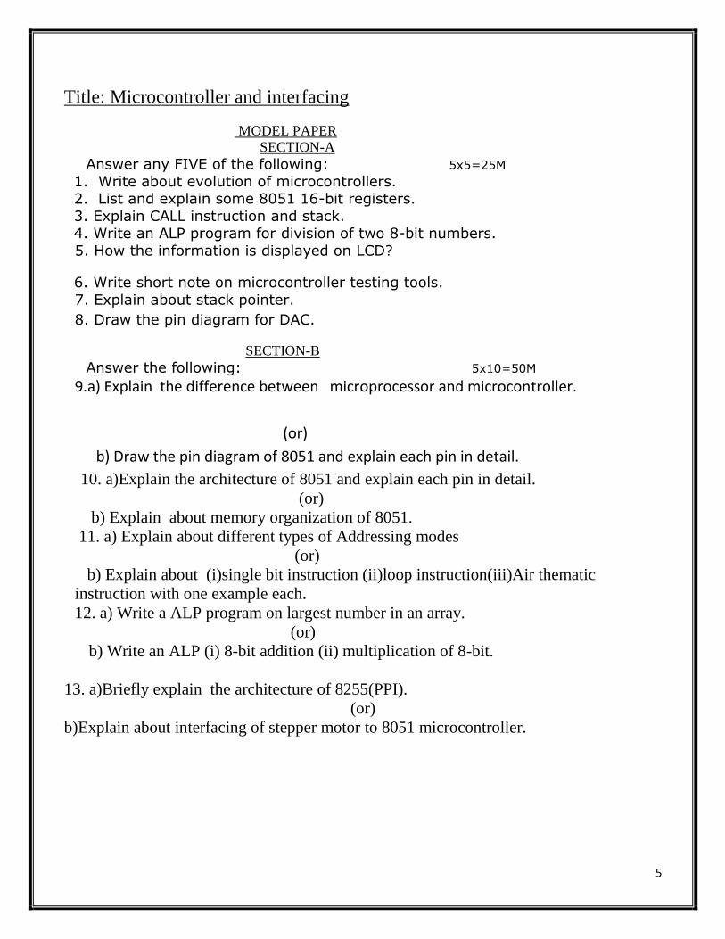
Title: Microcontroller and interfacing
MODEL PAPER
SECTION-A
Answer any FIVE of the following: 5x5=25M
1. Write about evolution of microcontrollers. 2. List and explain some 8051 16-bit registers.
3. Explain CALL instruction and stack. 4. Write an ALP program for division of two 8-bit numbers.
5. How the information is displayed on LCD?
6. Write short note on microcontroller testing tools.
7. Explain about stack pointer.
8. Draw the pin diagram for DAC.
SECTION-B
Answer the following: 5x10=50M
9.a) Explain the difference between microprocessor and microcontroller.
(or)
b) Draw the pin diagram of 8051 and explain each pin in detail.
10. a)Explain the architecture of 8051 and explain each pin in detail.
(or)
b) Explain about memory organization of 8051.
11. a) Explain about different types of Addressing modes
(or)
b) Explain about (i)single bit instruction (ii)loop instruction(iii)Air thematic
instruction with one example each.
12. a) Write a ALP program on largest number in an array.
(or)
b) Write an ALP (i) 8-bit addition (ii) multiplication of 8-bit.
13. a)Briefly explain the architecture of 8255(PPI).
(or)
b)Explain about interfacing of stepper motor to 8051 microcontroller.

6
VI SEMESTER
Cluster Elective -A
PAPER- VIII (A1) EMBEDDED SYSTEMS DESIGN
OBJECTIVES:
• design embedded computer system hardware • design, implement, and debug multi-threaded application software that operates under real-time
constraints on embedded computer systems • use and describe the implementation of a real-time operating system on an embedded
computer system • formulate an embedded computer system design problem including multiple constraints, create
a design that satisfies the constraints, implement the design in hardware and software, and measure performance against the design constraints
• create computer software and hardware implementations that operate according to well-known standards
• organize and write design documents and project reports • organize and make technical presentations that describe a design.
UNIT 1: (10Hrs)
Introduction to Embedded Systems:
Embedded systems overview, Design Challenge, Processor Technology, IC Technology, and Design
Technology.
UNIT 2: (15Hrs)
Custom Single Purpose Processor – Hardware Development:
Introduction, Combinational logic, Sequential logic, Custom Single Purpose Processor Design, RT-
Level Custom Single-Purpose Processor.
UNIT 3: (15Hrs)
General Purpose Processor – Software Development:
Introduction, Basic Architecture, Operation, Programmer’s View, ASIPs, and Development Environment:
Host and Target Machines, Linker / Locators for Embedded Software, Getting Embedded Software into the
target system. Debugging Techniques: Testing on your Host Machine, and Instruction Set Simulators.
UNIT 4: (10Hrs)
RTWA for Embedded Systems:
Introduction, Pulse Width Modulators, LCD Controllers, Keypad Controllers, Stepper Motor
Controllers, Analog – to – Digital Converters, and Real Time Clocks.
UNIT 5: (10Hrs)
Advanced Communication Principles:

7
Parallel Communication, Serial Communication, Wireless Communication, Serial Protocols: I2C, CAN and
USB. Parallel Protocols: PCI BUS and ARM BUS. Wireless Protocols: Bluetooth, and IEEE 802.11.
TEXT BOOKS:
1. Embedded System Design – A Unified Hardware / Software Introduction By Frank Vahid / Tony
Givargis – WILEY EDITION.
2. Embedded Systems Architecture, Programming and Design – 2nd Edition By Raj Kamal – Tata
McGraw-Hill Education.
REFERENCES:
1. An Embedded Software Premier - David E- Siman, PEARSON Education
2. Embedded / real - time systems - DR. K.V.K.K. Prasad, dreamtech
3. The art of programming Embedded systems, Jack G. Ganssle, academic press
4. Intelligent Embedded systems, Louis L. Odette, Adison Wesly, 1991
OUTCOMES:
• The student can gain good knowledge on Embedded Systems and implement in practical
applications.
• An ability effectively as a member or leader on a technical team
• A commitment to quality, timeliness and continuous improvement
PROJECT WORK-VIII
STUDENTS HAS TO DO A GROUP PROJECT WORK DURING THIRD YEAR

8
Title: Embedded systems Design
MODEL PAPER
SECTION-A
Answer any FIVE of the following: 5x5=25M
1. Write about embedded system. 2. Explain about Combinational logic.
3. Discuss about instruction set simulator. 4. Write about LCD controllers.
5. Write a short note on Bluetooth.
6. Write short notes on ARM bus.
7. Explain about IC technology.
8. Draw the pin diagram for Pulse width modulators.
SECTION-B
Answer the following: 5x10=50M
1.a) List various application areas of embedded systems and give examples for each
application area?.
(or)
b) Explain about different technologies used in embedded systems.
2. a)Explain the design of custom single processor .
(or)
b) Discuss about RT-level custom single processor.
3. a) Explain about different debugging techniques
(or)
b) Describe the function of linker/locator for embedded software.
4. a) Explain about Real time clocks.
(or)
b) Discuss briefly about Stepper motor controllers.
5. a) Briefly explain about serial communication.
(or)
b) Explain the following terms in brief (i)I2C (ii)CAN.

9
VI SEMESTER
Cluster Elective- A
A2: ANALOG AND DIGITAL COMMUNICATIONS
OBJECTIVES:
• This course provides a thorough introduction to the basic principles and techniques used in analog and digital communications.
• The course will introduce analog and digital modulation techniques. • Communication receiver and transmitter design, baseband and band pass communication techniques, line
coding techniques, noise analysis, and multiplexing techniques. • The course also introduces analytical techniques to evaluate the performance of communication systems.
UNIT –I (10Hrs)
AMPLITUDE MODULATION:
Need for modulation, amplitude modulation-frequency spectrum of AM wave, representation of AM, power
relations in the AM wave. Generation of AM- Transistor modulators. Suppression of carrier, balanced
modulator, suppression of one side band- phase shift method.
UNIT –II (10Hrs)
FREQUENCY MODULATION:
Theory of FM, frequency spectrum of FM wave, narrow band FM, wide band FM, power contents of the
carrier and sidebands, Generation of FM signals – Reactance modulator.
UNIT –III (10Hrs)
BASIC RECEIVER CIRCUITS:
Noise – Thermal, Shot, Super heterodyne Receiver block diagram, FM receiver, discriminators- slope,
balanced slope & Ratio detector
UNIT –IV (12Hrs)
RADIO WAVE PROPAGATION:
Communication bands, Electromagnetic waves-properties and applications. PULSE MODULATION:
Introduction, Sampling theorem, PAM- Generation & Detection PWM- Generation & Detection, PPM-
Generation & Detection
UNIT –V (18Hrs)
DIGITAL COMMUNICATIONS:
PCM – Quantization noise, S/N ratio of PCM system, relation between S/N ratio & BW, Companding.
Advantages of digital over analog communications. Advantages of shift keying over digital communication,
Types of shift keying, ASK – Generation & Detection, FSK – Generation & Detection.
TEXT BOOKS:
1. Electronic Communications - George Kennedy
2. Antennas and Wave Propagation – G.S.N.Raju – PHI
3. Principles of communication system –Herbert Taub & D.L.Schilling
REFERENCES: 1. Electronic Communications – Roody & Colen
2. Communication Systems – Hayken --- 4th Edition
3. Advance Electronic communication system ---Tomasi wayne
4. Modern digital and analog communication system –B.P.lathi
OUTCOMES: On successful completion of the course students will be able to:
• The student can gain good knowledge on analog and digital communication
• Understand basic elements of a communication system

10
• Conduct analysis of baseband signals in time domain and in frequency domain
• Demonstrate understanding of various analog and digital modulation and demodulation techniques techniques.
• Analyse the performance of modulation and demodulation techniques in various transmission environments
ELECTRONICS LAB-V
COMMUNICATION LAB
LAB LIST:
(Any six experiments should be done)
1. AMPLITUDE MODULATION
2. AMPLITUDE DE-MODULATION
3. FREQUENCY MODULATION
4. FREQUENCY DE-MODULATION
5. PRE-EMPHASIS CIRCUIT
6. DE-EMPHASIS CIRCUIT
7. PULSE AMPLITUDE MODULATION
8. PULSE WIDTH MODULATION.
MODEL PAPER
SECTION-A
Answer any FIVE of the following: 5x5=25M
1. Explain about need for modulation. 2. Write short note on wide band FM. 3. Define the following terms.
(i)Thermal (ii) shot noise
4. What are the advantages of digital communication over analog communication? 5. Write a short note on amplitude shift keying .
6. State and prove Sampling theorem.
7. Explain the generation of FSK.
8. Explain the power relations in AM.
SECTION-B
Answer the following: 5x10=50M
1. a) Define amplitude modulation and explain about frequency spectrum of AM wave.
(or)
b) Explain about Suppression of one side band using phase shift method.
2. a)Explain about demodulation of FM
(or)
b) Explain how FM signals are generated using reactance modulator.

11
3. a) Explain about the principle and working of super hetro dyne receiver-AM
(or)
b)Discuss about the construction and working of Ratio detector.
4. a)Explain the block diagram of PAM and briefly explain each block.
(or)
b)Describe the generation and detection of PWM .
5. a)Explain the block diagram of PCM in detail.
(or)
b)Discuss briefly about ASK Phase shift keying .

12
VI SEMESTER
Cluster Elective : A
A3: POWER ELECTRONICS
Objectives:
• To study the characteristics of various power semiconductor devices.
• To understand the operation of power inverters.
• To study the operation of rectifiers with different loads.
• To understand the operation of different types of choppers.
• To understand the operation and controlling of motors.
Unit- 1 (12 Lectures)
Power Devices: Need for semiconductor power devices, Power diodes, Introduction to family of
thyristors.
Silicon Controlled Rectifier (SCR): structure, I-V characteristics, Turn-On and Turn-Off
characteristics, Factors affecting the characteristics of SCR, Control circuits design and Protection
circuits.
Unit- 2 (14 Lectures)
Diac and Triac: Basic structure, working and V-I characteristics of diac and triac.
Insulated Gate Bipolar Transistors (IGBT): Basic structure, I-V Characteristics, switching
characteristics.
Power MOS FETs: operation modes, switching characteristics, power BJT, second break down,
saturation and quasi-saturation state.
Unit- 3 (10 Lectures)
Choppers: Basic chopper circuit, types of choppers (Type A-D), step-down chopper, step-up chopper,
operation of d.c. chopper circuits using self commutation (A & B-type commutating circuit), Morgan's
chopper
Unit-4 (10 Lectures)
Power Inverters: Need for commutating circuits and their various types, d.c. link inverters, Parallel
capacitor commutated invertors with and without reactive feedback and its analysis, Series Inverter,
bridge invertors.
Unit- 5 (14Lectures)
Electromechanical Machines: DC Motors, Principle of operation, EMF equation, Back EMF, Factors
controlling motor speed, Thyristor based speed control of DC motors, AC motor (Induction Motor only),
Rotor and stator, torque & speed of induction motor.

13
Outcomes:
Student should be able to
• Explain the characteristics of various power semiconductor devices and analyze the static and dynamic
characteristics of SCR’s.
• Design firing circuits for SCR.
• Explain the operation of rectifiers with different loads.
• Analyze the operation of different types choppers.
Suggested Books:
1. Power Electronics, K. Hari Babu, Scitech Publication.
2. Power Electronics, P.C.Sen, TMH
3. Power Electronics & Controls, S.K. Dutta
4. Power Electronics, M.D.Singh&K.B. Khanchandani, TMH
5. Power Electronics Circuits, Devices and Applications, 3rd Edition, .H.Rashid, Pearson Education
6. Power Electronics, Applications and Design, Ned Mohan,Tore.
7. Power Electronics, P.C.Sen, TMH.
8. Power Electronics, M.S.Jamil Asghar,PHI.
9. A Textbook of Electrical Technology-Vol-II,B.L.Thareja,A.K.Thareja, S.Chand
ELECTRONICS LAB-X
Power Electronics Lab
LAB LIST:
(Any six experiments should be done)
1. Study of I-V characteristics of DIAC
2. Study of I-V characteristics of a TRIAC
3. Study of I-V characteristics of a SCR
4. SCR as a half wave and fullwave rectifier switch R and RL loads
5. DC motor control using SCR.
6. DC motor control using TRIAC.
7. AC voltage controller using TRIAC with UJT triggering.
8. Study of parallel and bridge inverter.
9. Design of snubber circuit
10. VI Characteristic of MOSFET and IGBT (Both)
11. Study of chopper circuits
14
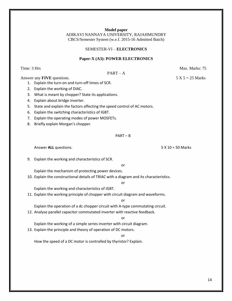
Model paper
ADIKAVI NANNAYA UNIVERSITY, RAJAHMUNDRY
CBCS/Semester System (w.e.f. 2015-16 Admitted Batch)
SEMESTER-VI – ELECTRONICS
Paper-X (A3): POWER ELECTRONICS
Time: 3 Hrs Max. Marks: 75
PART – A
Answer any FIVE questions. 5 X 5 = 25 Marks
1. Explain the turn-on and turn-off times of SCR.
2. Explain the working of DIAC.
3. What is meant by chopper? State its applications.
4. Explain about bridge inverter.
5. State and explain the factors affecting the speed control of AC motors.
6. Explain the switching characteristics of IGBT.
7. Explain the operating modes of power MOSFETs.
8. Briefly explain Morgan’s chopper.
PART – B
Answer ALL questions. 5 X 10 = 50 Marks
9. Explain the working and characteristics of SCR.
or
Explain the mechanism of protecting power devices.
10. Explain the constructional details of TRIAC with a diagram and its characteristics.
or
Explain the working and characteristics of IGBT.
11. Explain the working principle of chopper with circuit diagram and waveforms.
or
Explain the operation of a dc chopper circuit with A-type commutating circuit.
12. Analyse parallel capacitor commutated inverter with reactive feedback.
or
Explain the working of a simple series inverter with circuit diagram.
13. Explain the principle and theory of operation of DC motors.
or
How the speed of a DC motor is controlled by thyristor? Explain.
15
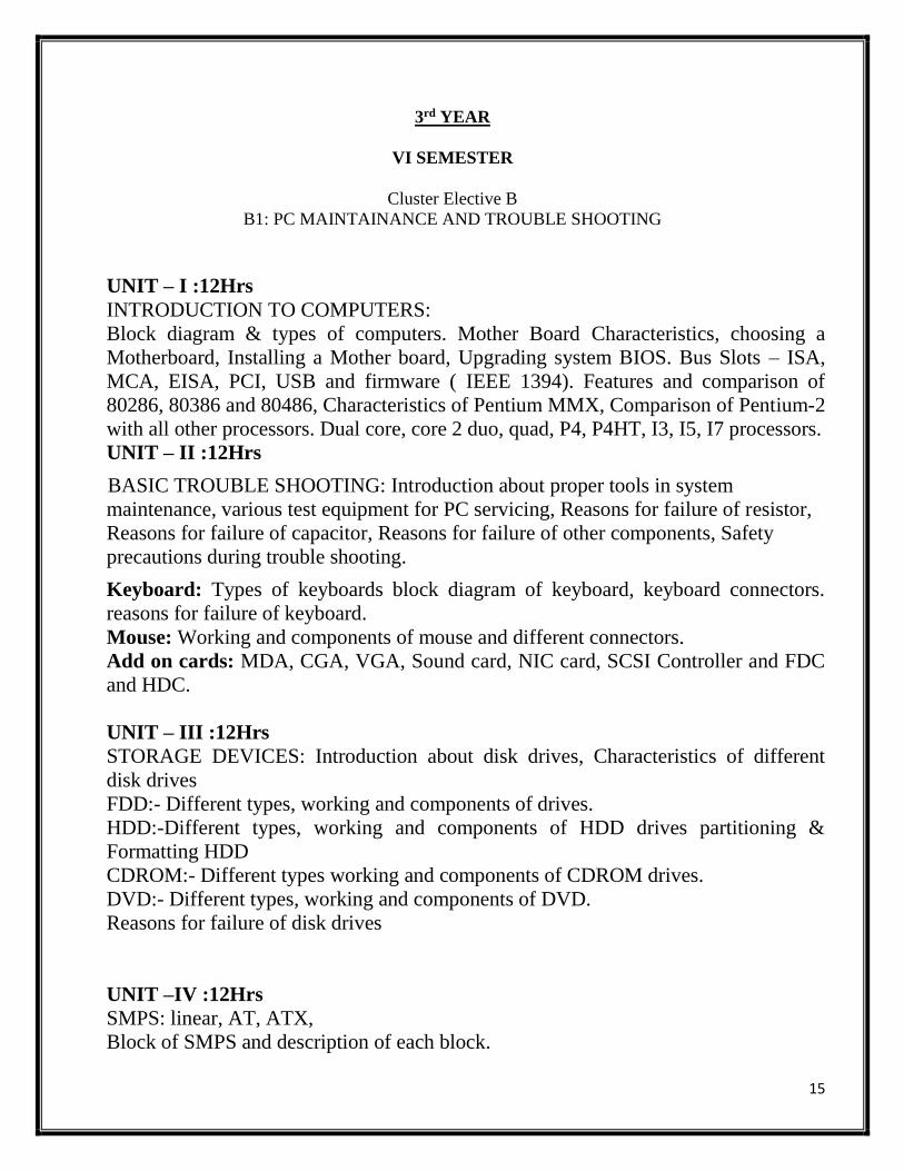
3rd YEAR
VI SEMESTER
Cluster Elective B
B1: PC MAINTAINANCE AND TROUBLE SHOOTING
UNIT – I :12Hrs
INTRODUCTION TO COMPUTERS:
Block diagram & types of computers. Mother Board Characteristics, choosing a
Motherboard, Installing a Mother board, Upgrading system BIOS. Bus Slots – ISA,
MCA, EISA, PCI, USB and firmware ( IEEE 1394). Features and comparison of
80286, 80386 and 80486, Characteristics of Pentium MMX, Comparison of Pentium-2
with all other processors. Dual core, core 2 duo, quad, P4, P4HT, I3, I5, I7 processors.
UNIT – II :12Hrs
BASIC TROUBLE SHOOTING: Introduction about proper tools in system
maintenance, various test equipment for PC servicing, Reasons for failure of resistor,
Reasons for failure of capacitor, Reasons for failure of other components, Safety
precautions during trouble shooting.
Keyboard: Types of keyboards block diagram of keyboard, keyboard connectors.
reasons for failure of keyboard.
Mouse: Working and components of mouse and different connectors.
Add on cards: MDA, CGA, VGA, Sound card, NIC card, SCSI Controller and FDC
and HDC.
UNIT – III :12Hrs
STORAGE DEVICES: Introduction about disk drives, Characteristics of different
disk drives
FDD:- Different types, working and components of drives.
HDD:-Different types, working and components of HDD drives partitioning &
Formatting HDD
CDROM:- Different types working and components of CDROM drives.
DVD:- Different types, working and components of DVD.
Reasons for failure of disk drives
UNIT –IV :12Hrs
SMPS: linear, AT, ATX,
Block of SMPS and description of each block.

16
INTRODUCTION to UPS& SPS:
Reasons for power supply failure, Impact of power supply failure on PC
MONITOR: Introduction about display units, Different display technologies, block
diagram, Reasons for display failure.
UNIT – V :12Hrs
PRINTERS:- Different types of printers, dot matrix, INKJET & LASER PRINTER –
components and working.
PREVENTIVE MAINTANCE – Effect of heat and noise, Effect of corrosion on PC,
Effect of power fluctuations, Effect of magnetic fields on system performance, EMI
effect, Virus protection, Tools and techniques of S/W trouble shooting.
TEXT BOOKS:
1. UPGRADING AND REPAIRING PC – SCOTT MULLER.
2. IBM PC and Clones: Hardware, Troubleshooting and Maintenance -
GOVINDARAJALU. B
REFERNCE BOOKS:
1. I.T. HARDWARE - NATSHELL.
2. PRINTER MANUALS.
ELECTRONICS LAB
PC MAINTENANCE AND TROUBLE SHOOTING LAB
LAB LIST:
1. Identification of different peripherals and components in a PC.
2. Identification of different types of motherboards.
3. Identification of different expansion slots and add-on cards.
4. Assembling a PC
5. Study of CMOS ROM BIOS setup utilities.
17
6. . Change of CMOS password and boot sequence
7. Connecting hard drives, floppy drives and DVD writer
8. Creating partitions and formatting a hard drive.
9. Installation of windows 2000 Professional and windows XP
10. Installation of application software’s and antivirus software
11. Installation of windows server 2003
12. Installation and configuring display sound and LAN cards.
18
3rd YEAR
VI SEMESTER
Cluster Elective B
B2: COMPUTER NETWORKS
UNIT-I :12Hrs
INTRODUCTION to OSI,TCP/IP and other Network models,Examples of
Networks,NovelNetworks,Arpanet,Internet,Networktopologies,WAN,LAN,MAN.
PHYSICAL LAYER :Transmitted media copper,Twistedparewireless,switching and
Encoding asynchronuscommunications,Narrowband,Broadband,ISDN& ATM.
UNIT-II :12Hrs
DATA LINK LAYER: Design issues,framing,error detection
&correction,CRC,elementary protocol-Stop and wait,Slidingwindow,slip,data link layer
in HDLC,Internet,ATM
UNIT-III :12Hrs
MEDIUM ACCESS SUB LAYER: ALOHA,MAC,Address,Carrier sense multiple
access,IEEE 802.X standard Ethernet,WirelessLAN,Bridges.
UNIT-IV :12Hrs
NETWORK LAYER: Virtual circuits and data gram sub nets-routing algorithm,shortest
path routing,fooding,Hierarchicalrouting,broadcast,multicast,distance vector routing
UNIT-V :12Hrs
TRANSPORT LAYER : Transport services,Connection management ,TCP & UDP
protocols,ATM AAL layers protocol
APPLICATION LAYER- Network security,domain name
system,SNMP,Electronicmail,The world web,multimedia
TEXT BOOKS:
Computer Networks - Andrew S.
Tanenbaum,4thEdition,Pearson education
Data communications & Networking -Behrouz A.Forouzan.3rdEditionTMH
References
An engineering approach to Computer Networks - S. Kesav 2ndEdition,Pearson
education

19
ELECTRONICS LAB
COMPUTER NETWORK LAB
1.Study of different types of network cables and practically implement the
cross wired cable and straight through cable using clamping tool
2.study of network Devices in detail.
3.Study of network IP
4.connect the computers in local area network
5.study of basic network command and network configuration command
6.confiqure a network topology using packet tracer software
7.confiqure a network using link state vector routing protocol

20
3rd YEAR
VI SEMESTER
Cluster Elective B
B3: ELECTRONIC INSTRUMENTATION
OBJECTIVES:
The student will be introduced to
• To introduce students to monitor, analyze and control any physical system
• To understand students how different types of meters work and their construction
• To Study of absolute is merely confirmed within laboratories
• To Study integrating instruments like ammeter, voltmeter
• To Measurement of impedance using bridges
• To Study of PLL ,ph-meter, PLC
UNIT-I (10hrs)
Measurements:
Basic block diagram of measurement system, Accuracy and precision, resolution, sensitivity, linearity, Errors,
systematic and random errors, standards &calibrations of an instrument.
Applications of instrument
UNIT –II (10hrs)
Basic Measurement Instruments: DC measurement-ammeter, voltmeter, ohm meter, AC measurement, Digital
voltmeter systems (integrating and non-integrating). Digital Multimeter; Block diagram principle of
measurement of I, V, C. Accuracy and resolution of measurement. Measurement of Impedance- A.C.
bridges, Measurement of Self Inductance (Anderson's bridge), Measurement of Capacitance (De Sauty
bridge), Measurement of frequency (Wien's bridge). UNIT-III (15hrs)
Lock-in-amplifier: Basic Principles of phase locked loop (PLL), Phase detector (XOR& edge triggered), Voltage
Controlled Oscillator (Basics, varactor), lock and capture. Basic idea of PLL IC (565 or 4046). Lock-in-amplifier
, Idea of techniques for sum and averaging of signals.
Signal Generators: Function generator, Pulse Generator, (Qualitative only).
UNIT-IV (15hrs)
Analytical instruments
Spectrophotometer, working with block diagram, features of spectrophotometer,
PH meter - principle working with block diagram, features of PH meter.
TEMPERATURE TRANSDUCERS
Standards and calibration, Fluid expansion and metal expansion type transducers, like bimetallic strip,
Thermometer, RTD, Thermo couple and their characteristics.
UNIT-V : ( 10hrs)
Direct digital control (DDC), Distributed control system (DCS),
PLC’S: Block diagram, hardware, PLC operation, basic logic program (ladder logic),
Applications of PLC’S
TEXT BOOKS
1. Introduction to instrumentation and control By A.K.Ghosh
2. Sensors and transducers PHI 2Ed By D.Patranabis.

21
3. Industrial instrumentation –Eckman.P.
4. Instrument measurement analysis By Nakra and chaudhry.
Reference Books:
1. W.D. Cooper and A. D. Helfrick, Electronic Instrumentation and Measurement
Techniques, Prentice Hall (2005).
2. E.O. Doebelin, Measurement Systems: Application and Design, McGraw Hill Book - fifth Edition (2003).
3. David A. Bell, Electronic Devices and Circuits, Oxford University Press (2015).
4. Alan S. Morris, “Measurement and Instrumentation Principles”, Elsevier
(Butterworth Heinmann-2008).
OUTCOMES:
• Design a system, component or process to meet desired needs in electrical engineering.
• Measurement of R,L,C ,Voltage, Current, Power factor , Power, Energy
• Ability to balance Bridges to find unknown values.
• .Ability to measure frequency, phase with Oscilloscope
• Ability to use Digital voltmeters
• Ability to measure strain, displacement, Velocity, Angular Velocity, temperature, Pressure ,Vacuum, and
Flow
ELECTRONICS LAB
ELECTRONIC INSTRUMENTATION LAB
LAB LIST:
1. Design of multi range ammeter and voltmeter using galvanometer.
2. Measurement of resistance by Wheatstone bridge and measurement of bridge sensitivity.
3. Measurement of Capacitance by De’Sautys.
4. Measure of low resistance by Kelvin’s double bridge.
5. To determine the Characteristics of resistance transducer - Strain Gauge (Measurement of Strain using half
and full bridge.)
6. To determine the Characteristics of LVDT.
7. To determine the Characteristics of Thermistors and RTD.
8. Measurement of temperature by Thermocouples and study of transducers like AD590 (two terminal
temperature sensor), PT-100, J- type, K-type.
9. To study the Characteristics of LDR, Photodiode, and Phototransistor.

22
B.Sc. Electronics CBCS SYLLABUS
Title: ELECTRONIC INSTRUMENTATION
MODEL PAPER SECTION-A
Answer any FIVE of the following: 5x5=25M
1.Define the terms (i)Accuracy (ii)Precision 2.What is Digital multimeter?
3.Write a short note on lock in amplifier? 4.Explain about thermo couple and characteristics.
5.Write short notes on Temperature Transducer.
6.Mention some applications of PLC.
7. Define the terms (i)Resolution (ii)Sensitivity.
8.Explain about ohm meter.
SECTION-B
Answer the following: 5x10=50M
2. a) Explain briefly about the block diagram of measurement system.
(or)
b) Define the following terms in brief :
(a)Systematic errors.
(b) Random errors.
2. a)Explain about Digital voltmeter systems in brief.
(or)
b) Discuss briefly about measurement of frequency(Wien bridge) .
3. a)Define principle and working characteristics of PLL.
(or)
b) Explain briefly about function generator.
4. a)Draw the block diagram of Spectrophotometer and explain.
(or)
b) Define principle and working characteristics of PH meter.
5.a) Discuss briefly about Direct digital control.
(or)
b) Explain about the block diagram of PLC and it’s operation.
Sub: ELECTRONICS
Year:2017-18 Group: B.Sc Credits 3

23
ANDHRA PRADESH STATE COUNCIL OF HIGHER EDUCATION
B. Sc ELECTRONICS SYLLABUS (2017-18)
3RD YEAR
VI SEMESTER
Cluster-2
PAPER- X (B3) OPTICAL FIBER COMMUNICATION AND IT’S APPLICATION
OBJECTIVES:
• To study about the concept of fiber optic communication.
• To study light source and detectors
• To study the different types of fiber measurements.
• To study the concept of link design
• Introduction to fiber optic communication Receiver
• To study about fiber optic measurement
• To study about Optic Fiber Sensors and applications.
UNIT I: (10Hrs)
Fiber optic communication:
The basic communications systems, Nature of light, Advantages of fiber, Applications of fiber optic
communications, Light wave fundamentals- Electromagnetic waves, Dispersion, Pulse distortion and information
rate, polarization, Resonant cavities, Reflection at a plane boundary, Critical – angle Reflections ; Optic fiber
waveguides: - Step-index fiber, Graded-index fiber, Attenuation. (Elementary Treatment only) .
UNIT II: (10Hrs)
Light source and detectors:
Light emitting diodes Operating characteristics, Laser diodes, Laser diode operating characteristics, Distributed
feedback laser diode, Optical amplifiers, Light detectors: Principles of photo detection, Photo multiplier, Semi
conductor photo diode, PIN photo diode, Avalanche photo diode.
UNIT III: (15Hrs)
MODULATION :
Light Emitting Diode Modulation and circuits, Laser diode modulation and circuits, Analog Modulation Format,
Digital modulations formats. SYSTEM LINK DESIGN: Analog system design, Digital system design, power
budget analysis.
UNIT IV: (15Hrs)
Optical Fiber Communication Receiver:
Introduction : Signal Path through Optical Data link, Receiver configuration with noise, Receiver noises, Noise at
the input to the Amplifier, Receiver Capacitance and Bandwidth , Block diagram of Optical Receiver, Automatic
Gain Control (AGC) circuit Fiber Optical Measurement: Introduction: Attenuation Measurement, Optical Time
Domain Reflecto-meter (OTDR), Time Domain Dispersion Measurement, Frequency Domain Dispersion
Measurements, Numerical Aperture Measurement using Scanning photo detector, measurement of losses in
Splice and Connectors.
UNIT V: (10Hrs)
Fiber Optical Sensors and Applications:

24
Fiber Optic Sensor: Generalised Optical Fiber sensors, Phase and Polarization Fiber sensor, Optical Fluid Level
Detector, Optical Fiber Flow Sensors, Optical Displacement sensors, Long haul communications , Local Area
Networks.
TEXT BOOKS:
1. Fiber Optic Communications by Joseph C.Palais (4th Edition, Pearson Education)
2. Opto-electronics and Fiber Optic communications by C.K.Sarkar and D.C.Samkar
3. Fiber Optic Communications by S.Sankar. (New age international)
REFERENCE BOOKS:
1. Fiber Optic communication by senior-PHI
2. Fiber Optic communications Technology – Djafar k.Mynbaev, Lowell L. Scheiner.
3. Otical fiber communication-Gerd Kaiser
4. Optical communication system-John Gowar.
OUTCOMES:
• This course provides the students with the basic understanding of the concepts and principles of optical
fibre communications.
• Line transmission systems,- analog and digital transmission system standards.
• On completion of the course, the students will be able to apply the knowledge and principles leant to
analyze, design, install and manage typical wired and wireless communication systems and networks
ELECTRONICS LAB-X
OPTICAL FIBER COMMUNICATION LAB
LAB LIST:
ABOUT FIBER OPTICS.
1: SETTING FIBER OPTIC ANALOG LINK
2: SETTING FIBER OPTIC DIGITAL LINK
3: STUDY OF LOSSES IN OPTICAL FIBER
4: BENDING LOSSES IN FIBER
5: STUDY OF NUMERICAL APERTURE OF OPTICAL FIBER
6: STUDY OF CHARACTERISTICS OF FIBER OPTIC LED.
7: STUDY OF TIME DIVISION MUTIPLEXING (DIGITAL)

25
Title: Optical fiber communication and it’s applications
MODEL PAPER
SECTION-A
Answer any FIVE of the following: 5x5=25M
1. Explain about Nature of light.
2. Write about semiconductor photo diode. 3. Discuss about power budget analysis.
4. Explain about signal path trough data link
5. Write short note on fiber flow sensor.
6. Define the following terms(i)polarization (ii)Resonant cavities.
7. Explain about PIN photodiode
8. Write about Optical amplifiers..
SECTION-B
Answer the following: 5x10=50M
1. a)Explain briefly about the advantages and applications of OFC.
(or)
b) Discuss about Reflection at a plane of boundary.
2. a)Define Laser principles and explain it’s operating characteristics.
(or)
b) Define the following terms (i)APD (ii)PMT.
3. a) Define modulation and explain about Analog formats..
(or)
b) Discuss briefly about digital system design.
4. a) Draw the block diagram of optical receiver and explain in detail.
(or)
b) Explain numerical aperture measurement using scanning photo detector
5. a)Discuss briefly about fiber optic sensors.
(or)
b)Explain about Long haul communication.