ADHESIVE BONDING FOR STRUCTURAL MARINE...
6
International Conference on Innovation in High Performance Sailing Yachts ©2008: The Royal Institution of Naval Architects ADHESIVE BONDING FOR STRUCTURAL MARINE APPLICATIONS A Roy, CRITT MPC, France. Y Nadot, ENSMA, France. P Casari, GeM – UMR CNRS 6183, France. SUMMARY In order to make the structural junction in a sailing boat, for example between the shell and the bulkheads, many nautical builders use overlap joints. This technique is expensive and could be replaced by direct adhesive junction without overlap. Structural adhesive bonding has been tested on three boats prototypes : a motor boat of 5.75 m long, and two sailing boats one of 5.5 m long and one of 10 m long. The originality of those boats is the measurement device using strain gages included on some of the junctions during the boats construction. Gages and sensors have also been placed on the shell, the keel and the rigging: the stress state of the bonded junctions under sailing in different conditions can then be qualified. Therefore, testing has been managed on specimens. A coupled loads tests (bending + compression) on tee samples seems more pertinent to qualify tee junction for shipbuilding applications. 1. INTRODUCTION Usually, in pleasure shipbuilding, the composite shells are stiffened either by the way of one composite counter- mould bonded with a non structural adhesive or with a stiffener or bulkheads over laminated on the hull. For economical reasons, the first method is generally used only for large boats or large scale productions. In the manufacturing of small pleasure boats (motorboats and sailing boats from about 5 to 8 meters long) the assembly of different components, like the deck-hull and bulkhead-hull connections, are time consuming. They can account for up to 30% of the total manufacturing time. In order to reduce this time and the associated labour costs the use of adhesive bonding can be an interesting method to replace the over lamination, even for structural bonding like bulkheads-hull joints. Few woks deal on the mechanical behaviour of structural tee joints used in shipbuilding [1-8]. To validate this manufacturing option a research programme including research centres, adhesive manufacturers and boatyards started several years ago. This paper revue mains experiments made on three boats prototypes : a motor boat of 5.75 m long, and two sailing boats one of 5.5 m long and one of 10 m long. The originality of those boats is the measurement device using strain gages included on some of the junctions during the boats construction. Gages and sensors have also been placed on the shell, the keel and the rigging: the real stress state of the bonded junctions under sailing in different conditions can then be qualified. Therefore, testing has been managed on specimens. The following parts resume the studies made on the three prototypes and on tee joints samples (Figure 1). Adhesive is a vinylester one, it was selected and studied in the Prisca Baur thesis [8]. 2. FIRST PROJECT WITH A MOTOR BOAT OF 5,75 METERS LONG The aim of the first project was to study the feasibility of deck-hull and bulkhead-hull assembling using adhesive bonding. Three adhesives were evaluated: orthophthalic polyester, isophthalic polyester and vinylester. It should be noted that epoxy based adhesives were considered to be too expensive for this application. First, the adhesive properties were characterised. The influence of fillers and the effects of moisture ageing have been particularly investigated [8, 9]. Simple-lap and tee joints have been tested in shear-tension for the former, and in bending and tension for the latter [8]. Structural bonded joint Shell Non structural polyester with short glass fibers Bulkhead Glass roving + polyester resin Over laminated joint Figure 1: Structural junction between the shell and the bulkheads by over lamination and structural bonding.
Transcript of ADHESIVE BONDING FOR STRUCTURAL MARINE...
International Conference on Innovation in High Performance Sailing Yachts
©2008: The Royal Institution of Naval Architects
ADHESIVE BONDING FOR STRUCTURAL MARINE APPLICATIONS A Roy, CRITT MPC, France. Y Nadot, ENSMA, France. P Casari, GeM – UMR CNRS 6183, France. SUMMARY In order to make the structural junction in a sailing boat, for example between the shell and the bulkheads, many nautical builders use overlap joints. This technique is expensive and could be replaced by direct adhesive junction without overlap. Structural adhesive bonding has been tested on three boats prototypes : a motor boat of 5.75 m long, and two sailing boats one of 5.5 m long and one of 10 m long. The originality of those boats is the measurement device using strain gages included on some of the junctions during the boats construction. Gages and sensors have also been placed on the shell, the keel and the rigging: the stress state of the bonded junctions under sailing in different conditions can then be qualified. Therefore, testing has been managed on specimens. A coupled loads tests (bending + compression) on tee samples seems more pertinent to qualify tee junction for shipbuilding applications. 1. INTRODUCTION Usually, in pleasure shipbuilding, the composite shells are stiffened either by the way of one composite counter-mould bonded with a non structural adhesive or with a stiffener or bulkheads over laminated on the hull. For economical reasons, the first method is generally used only for large boats or large scale productions. In the manufacturing of small pleasure boats (motorboats and sailing boats from about 5 to 8 meters long) the assembly of different components, like the deck-hull and bulkhead-hull connections, are time consuming. They can account for up to 30% of the total manufacturing time. In order to reduce this time and the associated labour costs the use of adhesive bonding can be an interesting method to replace the over lamination, even for structural bonding like bulkheads-hull joints. Few woks deal on the mechanical behaviour of structural tee joints used in shipbuilding [1-8]. To validate this manufacturing option a research programme including research centres, adhesive manufacturers and boatyards started several years ago. This paper revue mains experiments made on three boats prototypes : a motor boat of 5.75 m long, and two sailing boats one of 5.5 m long and one of 10 m long. The originality of those boats is the measurement device using strain gages included on some of the junctions during the boats construction.
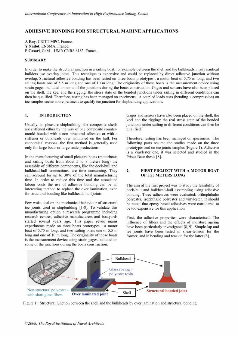
Gages and sensors have also been placed on the shell, the keel and the rigging: the real stress state of the bonded junctions under sailing in different conditions can then be qualified. Therefore, testing has been managed on specimens. The following parts resume the studies made on the three prototypes and on tee joints samples (Figure 1). Adhesive is a vinylester one, it was selected and studied in the Prisca Baur thesis [8]. 2. FIRST PROJECT WITH A MOTOR BOAT
OF 5,75 METERS LONG The aim of the first project was to study the feasibility of deck-hull and bulkhead-hull assembling using adhesive bonding. Three adhesives were evaluated: orthophthalic polyester, isophthalic polyester and vinylester. It should be noted that epoxy based adhesives were considered to be too expensive for this application. First, the adhesive properties were characterised. The influence of fillers and the effects of moisture ageing have been particularly investigated [8, 9]. Simple-lap and tee joints have been tested in shear-tension for the former, and in bending and tension for the latter [8].
Structural bonded joint Shell
Non structural polyester with short glass fibers
Bulkhead
Glass roving + polyester resin
Over laminated joint
Figure 1: Structural junction between the shell and the bulkheads by over lamination and structural bonding.

International Conference on Innovation in High Performance Sailing Yachts
©2008: The Royal Institution of Naval Architects
The behaviour of these assemblies was examined for the case when adhesive bonding replaces traditional joining methods. The influence of the geometry of these joints was also studied experimentally and with FEM calculations [8]. Finally, the fatigue behaviour of bonded and over-laminated T joints was investigated by Macadon and all. [10]. In parallel with tests carried out in the laboratory on sub-components, an adhesively-bonded prototype has been manufactured, instrumented and tested under real conditions (Figures 1 and 2). The adhesive selected is a vinylester based adhesive, it was retained on account of its superior long term behaviour. The shell is a 10 mm thick polyester/glass stratified composite. The structural bulkheads are 10 mm thick plywood (Figure 3). The adhesive is applied in a very simple way, no surface preparation of either the GRP or the plywood was performed prior to bonding. Figure 2: First prototype with structural adhesive bonding; motor boat of 5,75m long realised with Ocqueteau shipyard in Ile d’Oléron.
Figure 3: Adhesive bonded joint T joint studied and realised on the first boat prototype. For the bulkhead-hull assembly, the bulkheads were placed in position in the boat without fixing, and then a length of adhesive was applied on each side of the bulkhead and manually smoothed. The time needed for this operation is 45 minutes, whereas the over-laminating operation requires 4 hours. The boat was instrumented with sensors composed of strain gauge combinations; these are directly bonded to the adhesive joint of a bulkhead-hull connection. A full Wheatstone bridge is built (four 120 ohm gauges) in order to increase the sensitivity and the wiring is adapted
in order to concentrate on the loading of interest. For tension-compression sensors rosettes of 0-90° gauges are placed on each side of the joint and the wiring is chosen in order to eliminate the bending effect. This sensor is located on the main central perpendicular bulkhead. For the bending sensor the same positioning of the gauges is performed but the wiring differs in order to eliminate the tension – compression effect. For the shear sensor the gages are placed at 45° to the connection axis. It should also be noted that the wiring of the shear sensors results in a sensitivity twice that of the other sensors. The bending and shear sensors are placed symmetrically on the back of the two longitudinal bulkheads. An HBM Spider™ acquisition data system coupled to a portable computer is used to collect the data. Depending on the type of test a 2 or 10 second data sequence is recorded. Data recording is triggered by a signal increase. Drop tests have been performed in the IFREMER test basin in Brest. Different configurations have been retained for those tests: the boat was empty or loaded with 600 kg and drops are made from 1 metre to 2 meters high. Examples of result are presented on the plots below, Figure 4.
bending
-3
-2
-1
0
1
2
-0,28
-0,18
-0,08
0,02
0,12
signal(mV/V)
strain(%)
time≈ 2 seconds
1m_horizontal1m_starboard1m_port2m_horizontal1m_loaded
Figure 4: Examples of measurements during drop test. The sea trials were also performed in the Atlantic Ocean off the West coast of France. During navigation the boat was loaded with three passengers. The sea conditions were quite good (sea condition level 3-4) with a 30 cm high wave. The measurements were made at a maximum
International Conference on Innovation in High Performance Sailing Yachts
©2008: The Royal Institution of Naval Architects
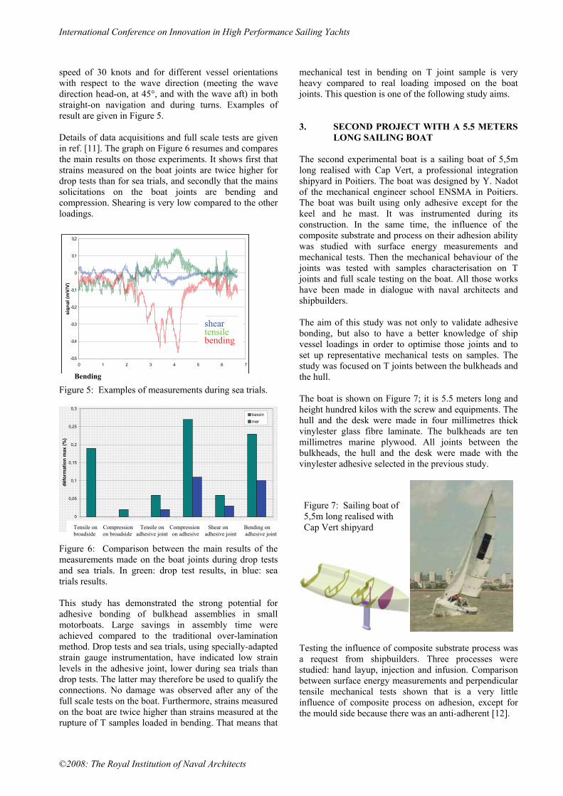
speed of 30 knots and for different vessel orientations with respect to the wave direction (meeting the wave direction head-on, at 45°, and with the wave aft) in both straight-on navigation and during turns. Examples of result are given in Figure 5. Details of data acquisitions and full scale tests are given in ref. [11]. The graph on Figure 6 resumes and compares the main results on those experiments. It shows first that strains measured on the boat joints are twice higher for drop tests than for sea trials, and secondly that the mains solicitations on the boat joints are bending and compression. Shearing is very low compared to the other loadings.
-0,5
-0,4
-0,3
-0,2
-0,1
0
0,1
0,2
0 1 2 3 4 5 6 7
temps(s)
sign
al (m
V/V)
Cisaillement
Traction
Flexion
sheartensilebending
time (s) Figure 5: Examples of measurements during sea trials.
0
0,05
0,1
0,15
0,2
0,25
0,3
traction bordé compressionbordé
traction compression cisaillement flexion
défo
rmat
ion
max
(%)
bassin
mer
Figure 6: Comparison between the main results of the measurements made on the boat joints during drop tests and sea trials. In green: drop test results, in blue: sea trials results. This study has demonstrated the strong potential for adhesive bonding of bulkhead assemblies in small motorboats. Large savings in assembly time were achieved compared to the traditional over-lamination method. Drop tests and sea trials, using specially-adapted strain gauge instrumentation, have indicated low strain levels in the adhesive joint, lower during sea trials than drop tests. The latter may therefore be used to qualify the connections. No damage was observed after any of the full scale tests on the boat. Furthermore, strains measured on the boat are twice higher than strains measured at the rupture of T samples loaded in bending. That means that
mechanical test in bending on T joint sample is very heavy compared to real loading imposed on the boat joints. This question is one of the following study aims. 3. SECOND PROJECT WITH A 5.5 METERS
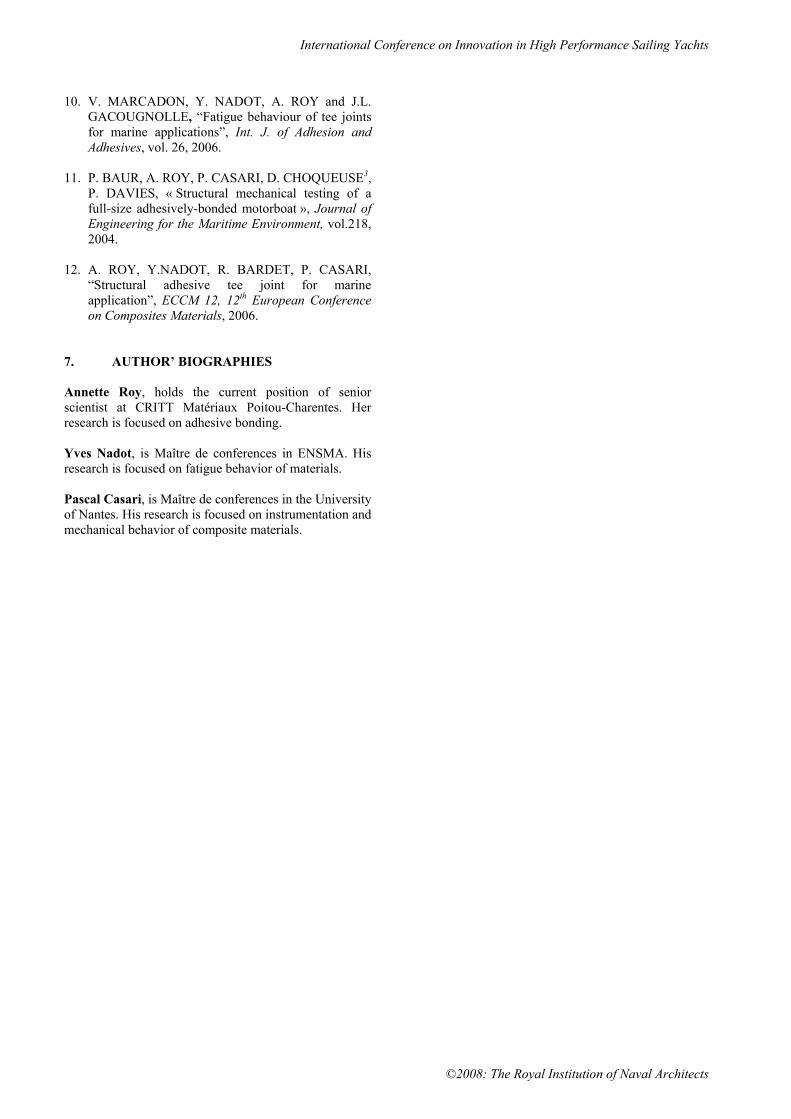
LONG SAILING BOAT The second experimental boat is a sailing boat of 5,5m long realised with Cap Vert, a professional integration shipyard in Poitiers. The boat was designed by Y. Nadot of the mechanical engineer school ENSMA in Poitiers. The boat was built using only adhesive except for the keel and he mast. It was instrumented during its construction. In the same time, the influence of the composite substrate and process on their adhesion ability was studied with surface energy measurements and mechanical tests. Then the mechanical behaviour of the joints was tested with samples characterisation on T joints and full scale testing on the boat. All those works have been made in dialogue with naval architects and shipbuilders. The aim of this study was not only to validate adhesive bonding, but also to have a better knowledge of ship vessel loadings in order to optimise those joints and to set up representative mechanical tests on samples. The study was focused on T joints between the bulkheads and the hull. The boat is shown on Figure 7; it is 5.5 meters long and height hundred kilos with the screw and equipments. The hull and the desk were made in four millimetres thick vinylester glass fibre laminate. The bulkheads are ten millimetres marine plywood. All joints between the bulkheads, the hull and the desk were made with the vinylester adhesive selected in the previous study.
Testing the influence of composite substrate process was a request from shipbuilders. Three processes were studied: hand layup, injection and infusion. Comparison between surface energy measurements and perpendicular tensile mechanical tests shown that is a very little influence of composite process on adhesion, except for the mould side because there was an anti-adherent [12].
Bending
Tensile on Compression Tensile on Compression Shear on Bending on broadside on broadside adhesive joint on adhesive adhesive joint adhesive joint
Figure 7: Sailing boat of 5,5m long realised with Cap Vert shipyard

International Conference on Innovation in High Performance Sailing Yachts
©2008: The Royal Institution of Naval Architects
Then adhesive bonded and over-laminated joints are tested in tensile and flexion [12]. The mechanical strength ordering depends of the type of loading : in tensile, the bonded joint as a failure load 30% higher than the over laminated joint as in bending it is the over laminated joint which is two higher strong. Those results shown that more representative tests of the structure loadings are required even for comparison of joints types. In order to evaluate the type of loading applied on bonded junctions, the experimental sailing boat was instrumented and tested during sailing, tailgating shocks and drop tests. Loadings applied on the keel have been measured with a special sensor developed especially for this study (Figure 8).
Figure 8: Special sensor developed to measure efforts applied on the keel.
Strain gages bridges have been glued on the adhesive joints and on the substrates on both sides of the joints (Figures 9). Gages connections have been made in order to identify especially the tensile and compression in the bulkheads, the shearing of the adhesive and the bending of the T joints. Figure 10 shows examples of strain gages signals in conditions of sailing and drop tests. It can be seen that the loading is very short, they are transient phenomenon. Furthermore, the stress analysis shows that the Von Misses stresses in the adhesive joint are much closed: 5 MPa for sailing and 6 MPa for drop tests; it is very lower than the failure strength of the adhesive which is 35 MPa. Effectively, any failure was observed in the adhesive joints after sailing and drop tests. The failure finally occurs in the main plywood bulkhead, after five drop tests from 0.5 to 1 m high.
Figure 9: Instrumentation of bulkhead-hull bonded joints.
Figure 10: examples of acquisition data measured during sailing and drop test. The mechanical analysis of the acquisitions during sailing and drop tests shows that the stress field in the adhesive joints is nearly the same: the major loading on the T joints is a coupling of bending and compression as it is shown on Figure 11). So that, an experimental setting was set up for testing T joints samples with various ratio bending/compression. Results show that the flexion strength of bonded T joints increases with compression component [12].
Figure 11: Proposition of coupled loading on Tee samples. 4. CONCLUSION Adhesive bonding for structural joints has been tested on two experimental boats during sea trials and drops in basin. Those tests shown that bonding seem a very

International Conference on Innovation in High Performance Sailing Yachts
©2008: The Royal Institution of Naval Architects
pertinent method to joint structural elements of a boat, namely for composite parts. In the same time, tests qualifications have been managed on tee samples. Test with simple solicitation as bending and tensile show that the mechanical strength ordering of bonded joints and over laminated ones depends of the type of loading. So a more representative test of the structure loadings are required even for comparison of joints types. Furthermore, strains measured on the boat during sea trials and without any failure are twice higher than strains measured at the rupture of T samples loaded in bending. A combined loads tests (bending + compression) on tee samples has shown that the flexion strength increase with the compression component. So that kind of coupled tests seems more pertinent to qualify tee junction for shipbuilding applications. To validate the adhesive bonding on a longer boat, a third experimental boat has been made with the Archambault shipyard. This is a regatta sailboat, a Grand Surprise, which is about 10 meters long. The main stiffener and bulkheads are bonded with the vinylester adhesive tested in the two previous projects. Our Grand Surprise, is tested in sailing and regattas since May 2006. No visible damage or modification during sailing has been noticed for two hears. Figure 12: Regatta sailing boat made using adhesive bonding.
5. AKNOWLEDGEMENTS Authors acknowledge all industrial partners of those studies and the sponsors: DRIRE Poitou-Charentes, Région Poitou-Charentes, Conseil Général de Charente Maritime and ANRT. 6. REFERENCES 1. SHENOI R.A., VIOLETTE F.L.M., "A study of
structural composite tee joints in small boats", Journal of composite materials, vol. 24, 1994.
2. HAWKINS G. L., HOLNES J.W, DODKINS A.R.,
SHENOI R.A., "The strength of bonded joints in FRP ships", Plastics, rubber and composites processing and applications, vol. 19 N°5, 1993.
3. HAWKINS G. L., DODKINS A.R., SHENOI R.A.,
"Design of joints and attachments in FRP ships' structures", Marine structures 7 365-398, 1994.
4. HAWKINS G. L., SHENOI R.A., "Influence of
material and geometry variations on the behaviour of bonded tee connections in FRP ships", Composites Vol 23 N°5, September 1992.
5. JUNHOU P., SHENOI R.A., "Examination of key
aspects defining the performance characteristics of out-of-plane joints in FRP marine structures", Composites Part A Vol 27 N°2, 1996.
6. A. ROY, E. GONTCHAROVA-BENARD, J.L.
GACOUGNOLLE, P. DAVIES, "Hydrothermal effects on failure mechanisms of composites/steel bonded joints”, Time Dependent and Nonlinear Effects in Polymers and Composites, ASTM Special Technical Publication, STP 1357, 2000.
7. M. HUTHER, A. ROY, J.L. GACOUGNOLLE, E.
GONCHAROVA, P. DAVIES, “Adhesive bonding of steel and fibreglass plates for shipbuilding”, 54th Annual Assembly of the International Institute of Welding, Ljubljana, July 2001.
8. BAUR P., «Durabilité d’assemblages structuraux
collés avec des adhésifs polyesters et vinylesters dans la construction navale de plaisance", Thèse de Doctorat, Ecole Nationale Supérieure de Mécanique et d’Aéronautique, Université de Poitiers, 2002.
9. P. BAUR, A. ROY, J.L. GACOUGNOLLE,
« Durabilité d’assemblages structuraux de composites collés avec des adhésifs polyesters et vinylesters dans la construction navale de plaisance », 11e Journées d’Etudes sur l’Adhésion, « Le Vide: Science, Technique et Applications », 8-12 octobre 2001.
International Conference on Innovation in High Performance Sailing Yachts
©2008: The Royal Institution of Naval Architects
10. V. MARCADON, Y. NADOT, A. ROY and J.L. GACOUGNOLLE, “Fatigue behaviour of tee joints for marine applications”, Int. J. of Adhesion and Adhesives, vol. 26, 2006.
11. P. BAUR, A. ROY, P. CASARI, D. CHOQUEUSE3,
P. DAVIES, « Structural mechanical testing of a full-size adhesively-bonded motorboat », Journal of Engineering for the Maritime Environment, vol.218, 2004.
12. A. ROY, Y.NADOT, R. BARDET, P. CASARI,
“Structural adhesive tee joint for marine application”, ECCM 12, 12th European Conference on Composites Materials, 2006.
7. AUTHOR’ BIOGRAPHIES Annette Roy, holds the current position of senior scientist at CRITT Matériaux Poitou-Charentes. Her research is focused on adhesive bonding. Yves Nadot, is Maître de conferences in ENSMA. His research is focused on fatigue behavior of materials. Pascal Casari, is Maître de conferences in the University of Nantes. His research is focused on instrumentation and mechanical behavior of composite materials.