ADELPHIA GATEWAY PROJECT · 1 1 GENERAL PROJECT DESCRIPTION Pursuant to Section 7(c) of the Natural...
53
ADELPHIA GATEWAY, LLC RESOURCE REPORT NO. 1 General Project Description ADELPHIA GATEWAY PROJECT January 2018
Transcript of ADELPHIA GATEWAY PROJECT · 1 1 GENERAL PROJECT DESCRIPTION Pursuant to Section 7(c) of the Natural...
ADELPHIA GATEWAY, LLC
RESOURCE REPORT NO. 1
General Project Description
ADELPHIA GATEWAY PROJECT
January 2018

SUMMARY OF FILING INFORMATION
INFORMATION Data Sourcesa Found in
Section
To be
Filed
Minimum Requirements to Avoid Rejection:
1. Provide a detailed description and location map of the Project facilities – Title 18 CFR § 380.12(c)(1)
D 1.2, 1.3, 1.4,
Appendix 1A
N/A
2. Describe any non-jurisdictional facilities that would be built in association with the Project – 18 CFR § 380.12(c)(2)
D 1.10 N/A
3. Provide current original USGS 7.5-minute-series topographic maps with mileposts showing the Project facilities - 18 CFR § 380.12(c)(3)
D Appendix 1A N/A
4. Provide aerial images or photographs or alignment sheets based on these sources with mileposts showing the Project facilities. - 18 CFR § 380.12(c)(3)
D Appendix 1A N/A
5. Provide plot/site plans of compressor stations showing the location of the nearest NSA within 1 mile - 18 CFR § 380.12(c)(3,4)
D Appendix 1B N/A
6. Describe construction and restoration methods - 18 CFR § 380.12(c)(6)
D 1.5 N/A
7. Identify the permits required for construction across surface waters - 18 CFR § 380.12(c)(9)
N/A N/A N/A
8. Provide the names and address of all affected landowners and certify that all affected landowners would be notified as required in § 157.6(d) - 18 CFR § 380.12(c)(10).
D Appendix 1E N/A
CFR
N/A
NSA
USGS
=
=
=
=
Code of Federal Regulations
Not applicable
noise sensitive area
United States Geological Survey
a D = Applicant
Source: FERC, 2017
TABLE OF CONTENTS
1 GENERAL PROJECT DESCRIPTION ..................................................................... 1
1.1 PURPOSE AND NEED ..................................................................................................................... 1
1.2 PROJECT DESCRIPTION ................................................................................................................ 1 1.2.1 Existing Facilities ........................................................................................................................... 3 1.2.2 New Facilities ................................................................................................................................ 5
1.3 LOCATION AND DESCRIPTION OF PROJECT FACILITIES ........................................................ 7 1.3.1 Pipeline Laterals and Meter Stations .......................................................................................... 10 1.3.2 Compressor Stations ................................................................................................................... 12 1.3.3 Mainline Valve and Blowdown Assemblies ................................................................................. 13 1.3.4 Martins Creek Station .................................................................................................................. 14 1.3.5 Wareyard ..................................................................................................................................... 14
1.4 LAND REQUIREMENTS ................................................................................................................ 14 1.4.1 Mainline Valves and Blowdown Assemblies ............................................................................... 15 1.4.2 Pipeline Laterals and Meter Stations .......................................................................................... 15 1.4.3 Aboveground Facilities ................................................................................................................ 16
1.5 CONSTRUCTION PROCEDURES ................................................................................................. 17 1.5.1 Marking Workspace .................................................................................................................... 17 1.5.2 Clearing and Grading .................................................................................................................. 17 1.5.3 Facility-specific Construction Procedures ................................................................................... 18
1.6 OPERATION AND MAINTENANCE .............................................................................................. 26
1.7 FUTURE PLANS AND ABANDONMENT ...................................................................................... 26
1.8 STAKEHOLDER OUTREACH ....................................................................................................... 27
1.9 PERMITS AND APPROVALS ........................................................................................................ 27
1.10 NON-JURISDICTIONAL FACILITIES ............................................................................................ 29
1.11 CUMULATIVE IMPACTS ................................................................................................................ 30 1.11.1 Projects and Activities Considered .......................................................................................... 30 1.11.2 Potential Cumulative Impacts by Resource ............................................................................. 33
1.12 POST FILING REVIEW .................................................................................................................. 45
1.13 REFERENCES ................................................................................................................................ 46
LIST OF APPENDICES
Appendix 1A Project Mapping
Appendix 1B Plot Plans
Appendix 1C Project Plans
Appendix 1D-1 Agency Correspondence – Public
Appendix 1D-2 Agency Correspondence - (CONTAINS PRIVILEGED
INFORMATION – Provided Under Separate Cover in Volume II)
Appendix 1E List of Affected Landowners (CONTAINS PRIVILEGED
INFORMATION – Provided Under Separate Cover in Volume II)

ACRONYMS AND ABBREVIATIONS
18-inch Mainline existing 84-mile, 18-inch-diameter, natural gas and petroleum pipeline
20-inch Mainline existing 4.5-mile, 20-inch-diameter, natural gas pipeline
Adelphia Adelphia Gateway, LLC
Application Application for a FERC Certificate of Public Convenience and Necessity
AST aboveground storage tank
ATWS additional temporary workspace
CEII Critical Energy Infrastructure Information
Certificate Certificate of Public Convenience and Necessity
CFR Code of Federal Regulations
Delmarva Station Delmarva-owned meter station (location of Parkway Lateral
interconnect facilities)
Existing System existing Interstate Energy Company, LLC pipeline system
FERC Federal Energy Regulatory Commission
FERC Plan FERC’s Upland Erosion Control, Revegetation, and Maintenance
Plan
FERC Procedures FERC’s Wetland and Waterbody Construction and Mitigation
Procedures
HDD horizontal directional drill
HP horsepower
IEC Interstate Energy Company, LLC
ILI in-line inspection
ISO International Standards Organization
M&R meter and regulator
MAOP maximum allowable pressure
Marcus Hook CS Marcus Hook Compressor Station
mmscfd million standard cubic feet per day
MLV mainline valve
MP milepost
NJR New Jersey Resources Corporation

Northern Segment existing pipeline segment from the Quakertown Compressor
Station to the Martins Creek Terminal
NSA noise sensitive area
PECO Philadelphia Electric Company
PennEast Project PennEast Pipeline Project
Project Adelphia Gateway Project
psig pounds per square inch gauge
Quakertown CS Quakertown Compressor Station
SCADA Supervisory Control and Data Acquisition
Southern Segment existing pipeline segment from the Quakertown Compressor
Station to the Marcus Hook Compressor Station
TCO Columbia Gas Transmission, LLC
TETCO Texas Eastern Transmission Company, LP
Tilghman Station existing interconnect between PECO and TETCO systems at
Tilghman Street
Transco Transcontinental Gas Pipe Line Company, LLC
TWS temporary work space
USDOT U.S. Department of Transportation
USGS U.S. Geological Survey

1
1 GENERAL PROJECT DESCRIPTION
Pursuant to Section 7(c) of the Natural Gas Act, Adelphia Gateway, LLC (Adelphia), an
indirect wholly-owned subsidiary of New Jersey Resources Corporation (NJR), is filing an
application for a Certificate of Public Convenience and Necessity (Certificate) with the Federal
Energy Regulatory Commission (FERC) for the construction and operation of its proposed
Adelphia Gateway Project (Project), which would be located in Pennsylvania and Delaware. In
support of this Application, Adelphia has prepared this environmental report according to Title
18 Code of Federal Regulations (CFR) §§ 157.14(a)(6-a), 380.3, and 380.12. This Certificate
Application (Application) is organized into four volumes in compliance with the FERC’s
document control requirements. Volume I contains Application text and related public exhibits.
Volumes II-IV contain the environmental report along with the Critical Energy Infrastructure
Information (CEII) and confidential Application exhibits.
1.1 PURPOSE AND NEED
Adelphia, an indirect wholly owned subsidiary of NJR, proposes to construct and
operate the Project facilities. The Project is designed to increase available natural gas pipeline
capacity to the Greater Philadelphia industrial region with potential to serve additional markets
in the Northeast while continuing to provide uninterrupted service to two existing power plants
at the northern end of the system, the Lower Mount Bethel Power Plant and the Martins Creek
Power Plant. The Project would achieve this objective by using and enhancing IEC’s existing
natural gas and oil pipeline system located in eastern Pennsylvania (Existing System). The
Existing System originates in Lower Chichester, Delaware County, Pennsylvania and travels
north to its terminus in Lower Mount Bethel Township, Northampton County, Pennsylvania.
The Project would provide customers in the greater Philadelphia region with a needed, new
source of clean, safe, low-cost supply.
1.2 PROJECT DESCRIPTION
The Project would use existing infrastructure to the greatest extent practicable and would
also require the construction and operation of some new facilities. The Project consists of the
following primary components, which are discussed in greater detail in sections 1.2.1 and 1.2.2:
• Two existing pipeline segments;
o 20-inch Mainline—an approximately 4.4-mile 20-inch natural gas pipeline beginning in Northampton County that transports natural gas to the Martins Creek Terminal in Lower Mount Bethel Township, Northampton County;

2
o 18-inch Mainline—an approximately 84-mile 18-inch pipeline, which originates in Lower Chichester, Delaware County, Pennsylvania, and travels north to its terminus in Lower Mount Bethel Township, Northampton County, Pennsylvania (the northern approximately 34-mile segment of the pipeline which has been used to transport dual products (oil and natural gas), and the southern approximately 50-mile segment which has been used to transport fuel oil) converted to transport solely natural gas;
• Two new compressor stations:
o Marcus Hook Compressor Station (Marcus Hook CS) in Delaware County, and
o Quakertown Compressor Station (Quakertown CS) in Bucks County, Pennsylvania;
• Two new pipeline laterals:
o Parkway Lateral, an approximately 0.25-mile 16-inch pipeline lateral that terminates at a new interconnect at an existing Delmarva-owned meter station (Delmarva Station) in Claymont, New Castle County, Delaware, and
o Tilghman Lateral, an approximately 4.5-mile 16-inch pipeline lateral that terminates at an existing interconnect between the Philadelphia Electric Company (PECO) and Texas Eastern Transmission Company, LP (TETCO) systems in Chester, Delaware County, Pennsylvania;
• Twelve meter and regulator (M&R) facilities :
o Existing Meter Stations—four existing meter stations will be used to provide natural gas transportation services in interstate commerce in the same manner they are currently used to provide natural gas transportation services in intrastate commerce:
▪ the Existing Quakertown M&R Station located at approximately MP 50 on the 18-inch Mainline connecting to the TETCO system;
▪ the Existing Columbia Gas Transmission, LLC (TCO) Meter Station located at approximately MP 66 on the 18-inch Mainline;
▪ the Existing Transcontinental Gas Pipe Line Company, LLC (Transco) M&R station located on the 20-inch Mainline, described in detail below; and
▪ the Existing Martins Creek Station, described in more detail below, located at the terminus of both the 18-inch Mainline and the 20-inch Mainline and connected to two power generation stations served by the Project;
o Skippack Meter Station—a new delivery interconnect in Skippack, Montgomery County, Pennsylvania;
o Quakertown M&R—a new receipt interconnect within the existing Quakertown M&R Station, which is described in detail below, in Bucks County, Pennsylvania;

3
o Parkway Lateral Interconnects—three new delivery interconnects—the TETCO Meter Station, the Columbia Gas Transmission, LLC (TCO) Meter Station, and the Delmarva Meter Station—on the property of the existing Delmarva Station in Delaware County, Pennsylvania; and
o Tilghman Lateral Interconnects—three new delivery interconnects—the Transco Meter Station, the Monroe Meter Station, and the PECO Meter Station—located in Delaware County, Pennsylvania;
• Eight new blowdown assemblies—one in Delaware County, two in Montgomery County, and five in Chester County, Pennsylvania;
• One new mainline valve located at one of two optional locations in Delaware County, Pennsylvania; and
• One wareyard located entirely within an existing industrial facility in Lower Chichester Township, Delaware County, Pennsylvania.
1.2.1 Existing Facilities
On October 27, 2017, Adelphia entered into an agreement with Talen Generation, LLC
(a subsidiary of Talen Energy Corporation) to purchase all of Talen Generation, LLC’s
membership interests in Interstate Energy Company, LLC (IEC), which owns and operates the
Existing System. The transaction is expected to close following receipt of all necessary permits
and regulatory actions, including those from the FERC.
The Existing System, which was built in the 1970s, is composed of the 18-inch Mainline
and the 20-inch Mainline that cross five counties in eastern Pennsylvania: Delaware; Chester;
Montgomery; Bucks; and Northampton Counties.
The 18-inch Mainline is an approximately 84-mile-long, 18-inch-diameter, and 1,083
pounds per square inch gauge (psig) maximum allowable pressure (MAOP), poly-coated
seamless steel line (18-inch Mainline) that IEC used to transport oil from Marcus Hook to the
Martins Creek Terminal in Lower Mount Bethel Township. The Martins Creek Terminal is part of
the larger Martins Creek Power Plant Complex, which houses the Martins Creek Power Plant and
the Lower Mount Bethel Power Plant. The southern approximately 50 miles of the 18-inch
Mainline (Southern Segment) is a fuel oil pipeline that has been idle since December 2014, and
the northern approximately 34 miles of the 18-inch Mainline (Northern Segment) is a dual use
(natural gas / oil) pipeline with existing receipt interconnects with the TETCO and TCO pipelines
that have been transporting natural gas exclusively since 2014. The Project would convert the
Southern Segment of the Existing System to natural gas service and reverse the flow from south-
to-north to north-to-south. The Project would also add compression at the existing Marcus Hook
4
Pump Station in Lower Chichester and at the existing TETCO Interconnect in Bucks County,
Pennsylvania to provide 250 million standard cubic feet per day (mmscfd) of capacity on the
Southern Segment.
The 20-inch Mainline is an approximately 4.4-mile-long, 20-inch-diameter, 1,200 psig
MAOP pipeline (20-inch Mainline) poly-coated steel line that begins in Northampton County and
is currently used by IEC to transport natural gas to the Martins Creek Terminal.
The entirety of the Existing System is protected by a previously installed cathodic
protection system. Appendix 1A provides an overview map of the Existing System.
As part of its purchase, Adelphia would acquire ancillary properties currently owned by
IEC, and four (4) existing meter stations in addition to the Existing System and use each as
described herein or below in section 1.2.2 (New Facilities):
• The Quakertown M&R Station - The Quakertown M&R Station is an approximately
1.5-acre site located at approximate latitude 40° 24' 15.98" N, longitude 75° 20'
53.95" W in Quakertown, Bucks County, Pennsylvania. Approximately half of the
site is graveled, industrial-use land, and the other half is covered by scrub/shrub
vegetation. Facilities onsite include an existing TETCO pipeline interconnect,
heaters, meters, regulators, and instrumentation and control buildings. This
existing station will be used to provide natural gas services in interstate commerce
in the same manner as this station currently provides natural gas services in
intrastate commerce. There are no proposed modifications to these facilities and
accordingly, there are no impacts to evaluate in this Environmental Report related
to the M&R facilities; however, as described in detail herein, a new receipt
interconnection and the new compressor station will be sited on the land within the
Quakertown M&R Station and those impacts are evaluated in this Environmental
Report;
• The Existing Transco M&R Station – The Transco M&R station is an approximately
1.6-acre paved and graveled site at approximate latitude 40° 45' 45.79" N,
longitude 75° 11' 51.60" W in Easton Township, Northampton County. Facilities
onsite include an existing Transco pipeline interconnect, heaters, meters,
regulators and instrumentation and control buildings. There are no proposed
modifications to these facilities and this site, and accordingly, there are no impacts
5
to evaluate in this Environmental Report related to the Existing Transco M&R
Station;
• The Existing Martins Creek Station – The Martins Creek Station is a 134.6-acre
site located at approximate latitude 40° 47' 37.62" N, longitude 75° 7' 52.36" W in
Lower Mount Bethel Township, Northampton County which will be subdivided from
the Martins Creek Terminal as part of the transaction. Martins Creek Terminal is
currently used as an oil storage and gas M&R station. As described below, the
Existing Martins Creek Terminal will be subdivided and Adelphia will own the
portion currently used as a gas M&R Station. Existing onsite facilities include
heaters, regulator runs, meters, control and maintenance buildings, a radio tower,
and onsite septic. There are no proposed modifications to these facilities and
accordingly, there are no impacts to evaluate in this Environmental Report related
to the M&R facilities; however, as described in detail herein, the construction
activities related to subdividing the existing station are evaluated in this
Environmental Report;
• The Existing TCO Meter Station – This existing station will be used to provide
natural gas services in interstate commerce in the same manner as this station
currently provides natural gas services in intrastate commerce. There are no
proposed modifications or disturbances to these facilities or at this site and
accordingly, there are no impacts to evaluate in this Environmental Report for the
Existing TCO Meter Station.
1.2.2 New Facilities
Adelphia proposes to install the following facilities along the Existing System
infrastructure:
• two new compressor stations
o the Marcus Hook CS, located at approximate latitude 39° 48' 53.25" N,
longitude 75° 26' 18.57" W in Lower Chichester. The Marcus Hook CS
would be located entirely within an existing paved/graveled industrial site;
o the Quakertown CS, located on land within existing Quakertown M&R
Station. Adelphia would also install a new receipt point/meter station within
the boundaries of the existing Quakertown M&R Station;

6
• a wareyard used as a laydown and materials storage yard located entirely within
the same existing paved/graveled industrial site as the Marcus Hook CS;
• two new pipeline laterals, both originating at the Marcus Hook CS and terminating
at new interconnect sites located within existing meter stations:
o The Parkway Lateral would be approximately 1,253 feet (0.2 mile), 16-inch-
diameter pipeline that terminates at new interconnects at the Delmarva
Station in Claymont, New Castle County, Delaware; Adelphia would also
install three new delivery meter facilities at the Delmarva Station to connect
with TETCO, TCO and Delmarva Gas;
o The Tilghman Lateral would be approximately 23,300 feet (4.4 miles),
16-inch-diameter pipeline that terminates at an existing interconnect with
the PECO and TETCO systems in Chester, Delaware County,
Pennsylvania (Tilghman Station). Adelphia would also install three new
delivery meter facilities along the Tilghman Lateral with Transco, the
Monroe Refinery, and PECO;
• a new meter station, called the Skippack Meter Station in Skippack, Montgomery
County, Pennsylvania, that would serve as a new delivery interconnect to an
existing PECO-owned pipeline;
• a new receipt interconnection within the Quakertown M&R Station;
• one new mainline valve (MLV)–Adelphia is currently considering two locations for
the siting of its new MLV (MLV Option 1 and MLV Option 2);
• eight blowdown assemblies at existing MLV sites along the Southern Segment;
• a new chain-link fence constructed within the boundaries of the Martins Creek
Terminal property that would delineate Adelphia’s new Martins Creek Station. The
Martins Creek Station would be created by a subdivision of the Martins Creek
Terminal as part of Adelphia’s IEC acquisition and would be located on 140 acres
of land (see section 1.10). Approximately 3.5 acres are paved and graveled and
contain the M&R equipment, heaters, control building, and a radio tower. The
remaining acreage is agricultural land; and
• various ancillary facilities including pig launchers and receivers, filter separators,
liquid disposal tanks, chromatography and communication equipment necessary

7
to monitor the operation of the pipeline, cathodic protection systems on the new
facilities which may consist of rectifiers and/or anode beds. All aforementioned
ancillary facilities would be installed and operated entirely within permanent
right-of-way.
1.3 LOCATION AND DESCRIPTION OF PROJECT FACILITIES
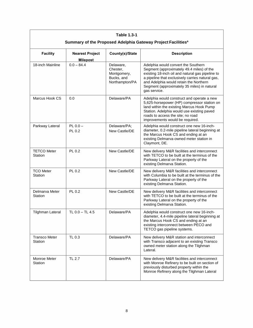
Adelphia is proposing to modify or construct the facilities as summarized in table 1.3-1
and depicted in appendix 1A. A summary of proposed locations for the MLV and blowdown
assemblies is provided in table 1.3-2. Detailed descriptions of each facility and the associated
proposed Project actions are provided below.
8
Table 1.3-1
Summary of the Proposed Adelphia Gateway Project Facilitiesa
Facility Nearest Project
Milepost
County(s)/State Description
18-inch Mainline 0.0 – 84.4 Delaware, Chester, Montgomery, Bucks, and Northampton/PA
Adelphia would convert the Southern Segment (approximately 49.4 miles) of the existing 18-inch oil and natural gas pipeline to a pipeline that exclusively carries natural gas, and Adelphia would retain the Northern Segment (approximately 35 miles) in natural gas service.
Marcus Hook CS 0.0 Delaware/PA
Adelphia would construct and operate a new 5,625-horsepower (HP) compressor station on land within the existing Marcus Hook Pump Station. Adelphia would use existing paved roads to access the site; no road improvements would be required.
Parkway Lateral PL 0.0 –
PL 0.2
Delaware/PA;
New Castle/DE
Adelphia would construct one new 16-inch-diameter, 0.2-mile pipeline lateral beginning at the Marcus Hook CS and ending at an existing Delmarva-owned meter station in Claymont, DE.
TETCO Meter Station
PL 0.2 New Castle/DE New delivery M&R facilities and interconnect with TETCO to be built at the terminus of the Parkway Lateral on the property of the existing Delmarva Station.
TCO Meter Station
PL 0.2 New Castle/DE New delivery M&R facilities and interconnect with Columbia to be built at the terminus of the Parkway Lateral on the property of the existing Delmarva Station.
Delmarva Meter Station
PL 0.2 New Castle/DE New delivery M&R facilities and interconnect with TETCO to be built at the terminus of the Parkway Lateral on the property of the existing Delmarva Station.
Tilghman Lateral TL 0.0 – TL 4.5 Delaware/PA Adelphia would construct one new 16-inch-diameter, 4.4-mile pipeline lateral beginning at the Marcus Hook CS and ending at an existing interconnect between PECO and TETCO gas pipeline systems.
Transco Meter Station
TL 0.3 Delaware/PA New delivery M&R station and interconnect with Transco adjacent to an existing Transco owned meter station along the Tilghman Lateral.
Monroe Meter Station
TL 2.7 Delaware/PA New delivery M&R facilities and interconnect with Monroe Refinery to be built on section of previously disturbed property within the Monroe Refinery along the Tilghman Lateral

9
PECO Meter Station
TL 4.4 Delaware/PA New delivery M&R facilities and interconnect with PECO to be built at the terminus of the Tilghman Lateral on the property of the existing Tilghman Station.
Skippack Meter Station
36.0 Montgomery/PA Adelphia would construct and operate a new meter station immediately adjacent to the intersection of the existing IEC line and an existing PECO-owned natural gas pipeline in Montgomery County. The meter station would include a fenced in area containing an M&R station and appurtenant facilities and equipment.
Quakertown CS 49.4 Bucks/PA Adelphia would construct and operate a new 5,625-HP compressor station and new meter station on land within the existing Quakertown M&R Station Site.
Quakertown Meter Station
49.4 Bucks/PA New receipt M&R facilities and interconnection between the 18-inch Mainline and TETCO to be built within the existing Quakertown M&R station.
20-inch Mainline 80.0 - 84.4 Northampton/PA Jurisdiction over this Project component would change from the Pennsylvania Public Utilities Commission to the FERC. No other modifications to this pipeline would occur, and it would remain in-service.
Martins Creek Station
84.4 Northampton/PA Work at this Site would be limited to the installation of an approximately 800-foot-long, 6-foot-tall chain-link fence. Adelphia would use existing paved roads to access the site; no road improvements would be required.
Wareyard 0.0 Delaware/PA
Adelphia would use the existing Marcus Hook Pump Station site for laydown and pipe storage; no improvements would be required.
MP = milepost
a Proposed MLV and blowdown assemblies are not included in this table and are instead provided in table 1.3-2.
Table 1.3-2
Summary of Proposed Mainline Valves and Blowdown Assemblies
Facility County/State Project MP Latitude/Longitude
Mainline Valves
MLV Option 1 Delaware/PA 6.7 39°53'52"N/ 75°29'19"W
MLV Option 2 Delaware/PA 7.9 39°54'44"N/
75°29'55"W

10
Table 1.3-2
Summary of Proposed Mainline Valves and Blowdown Assemblies
Facility County/State Project MP Latitude/Longitude
Blowdown Assemblies
Chester Creek Gate Blowdown
Delaware/PA 9.5 39°55'54"N/ 75°30'41"W
Paoli Pike Gate Blowdown Chester/PA 14.5 39°59'27"N/ 75°32'59"W
Pickering Creek Gate Blowdown
Chester/PA 23.0 40°05'56"N/ 75°34'15"W
French Creek Gate Blowdown Chester/PA 25.7 40°00’00”N/
75°32’57” W
Cromby Gate Blowdown Chester/PA 27.3 40°09’07”N/
75°31’59”W
Schuylkill River Gate Blowdown
Chester/PA 28.0 40°09’39”N/
75°31’42”W
Perkiomen Creek Gate Blowdown
Montgomery/PA 34.0 40°12’59”N/
75°27’14”W
East Perkiomen Gate Blowdown
Montgomery/PA 36.8 40°12’03”N/
75°26’30”W
1.3.1 Pipeline Laterals and Meter Stations
1.3.1.1 Parkway Lateral
The Parkway Lateral would be a 0.2-mile-long, 16-inch-diameter pipeline lateral used to
transport natural gas to new meter stations located within the existing Delmarva Station located
at approximate latitude 39° 48' 56.00" N, longitude 75° 26' 33.92" W in Claymont, New Castle
County, Delaware. Within the Delmarva Station, Adelphia would construct and install three
additional interconnect facilities to tie the proposed lateral in with other gas pipelines already
located at the Station. The Parkway Lateral would be installed entirely below ground, except for
meter and tie-in facilities located at the Marcus Hook CS and Delmarva Station. It would begin
within the Marcus Hook CS, be installed southwest along West Ridge Road within the paved road
right-of-way, continue northwest along Parkway Avenue (also within the paved road right-of-way),
continue along the south and western side of the Delmarva Station, and end within the Delmarva
Station. Adelphia would construct three new delivery point/meter stations at the terminus of the
Parkway Lateral within the boundaries of the existing Delmarva Station at approximate latitude
39° 48' 56.00" N, longitude 75° 26' 33.92" W.

11
1.3.1.2 Tilghman Lateral
The Tilghman Lateral would be an approximately 4.4-mile-long, 16-inch-diameter pipeline
that would transport natural gas from the Marcus Hook CS to the Tilghman Station. Adelphia
would construct three new delivery point/meter stations along the Tilghman Lateral:
• The Transco Meter Station would be located adjacent to an existing
Transco meter station at approximate Project milepost (MP) TL 0.3 along
Ridge Road in Lower Chichester at approximate latitude 39 º 49’ 5.5” N,
longitude 75 º 26’ 3.1” W;
• The Monroe Meter Station would be located at the Monroe Refinery at or
near MP TL 2.7 along Ridge Road in Lower Chichester at approximate
latitude 39 º 49’ 34.14” N, longitude 75 º 24’ 2.88” W; and
• The PECO Meter Station would be located at the existing Tilghman Station
near MP TL 4.4 at approximate latitude 39 º 50’ 7.22” N, longitude 75 º 22’
32.5” W.
The Monroe and PECO Meter Stations would be installed within existing industrial sites.
All new meter station facilities would include measurement, regulation, flow control, and
Supervisory Control and Data Acquisition (SCADA) monitoring equipment required to deliver
volumes to each customer/pipeline in accordance with the interconnection agreements negotiated
with each company and in accordance with Adelphia’s FERC-approved tariff.
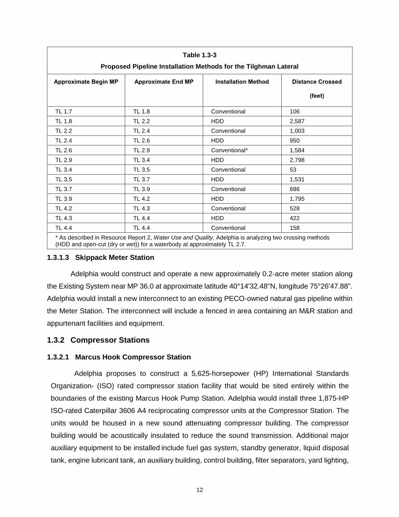
Outside of the receipt and delivery points, the majority of the Tilghman Lateral would be
installed below ground using horizontal directional drill (HDD) technology to minimize potential
impacts to the human and natural environments. Portions of the Tilghman Lateral would also be
installed below ground within paved road right-of-way. Table 1.3-3 provides details on proposed
installation methods for the Tilghman Lateral.
Table 1.3-3
Proposed Pipeline Installation Methods for the Tilghman Lateral
Approximate Begin MP Approximate End MP
Installation Method Distance Crossed
(feet)
TL 0.0 TL 0.3 Conventional 1,690
TL 0.3 TL 0.9 HDD 3,168
TL 0.9 TL 1.1 Conventional 898
TL 1.1 TL 1.7 HDD 3,379
12
Table 1.3-3
Proposed Pipeline Installation Methods for the Tilghman Lateral
Approximate Begin MP Approximate End MP
Installation Method Distance Crossed
(feet)
TL 1.7 TL 1.8 Conventional 106
TL 1.8 TL 2.2 HDD 2,587
TL 2.2 TL 2.4 Conventional 1,003
TL 2.4 TL 2.6 HDD 950
TL 2.6 TL 2.9 Conventional* 1,584
TL 2.9 TL 3.4 HDD 2,798
TL 3.4 TL 3.5 Conventional 53
TL 3.5 TL 3.7 HDD 1,531
TL 3.7 TL 3.9 Conventional 686
TL 3.9 TL 4.2 HDD 1,795
TL 4.2 TL 4.3 Conventional 528
TL 4.3 TL 4.4 HDD 422
TL 4.4 TL 4.4 Conventional 158
* As described in Resource Report 2, Water Use and Quality, Adelphia is analyzing two crossing methods (HDD and open-cut (dry or wet)) for a waterbody at approximately TL 2.7.
1.3.1.3 Skippack Meter Station
Adelphia would construct and operate a new approximately 0.2-acre meter station along
the Existing System near MP 36.0 at approximate latitude 40°14'32.48"N, longitude 75°26'47.88".
Adelphia would install a new interconnect to an existing PECO-owned natural gas pipeline within
the Meter Station. The interconnect will include a fenced in area containing an M&R station and
appurtenant facilities and equipment.
1.3.2 Compressor Stations
1.3.2.1 Marcus Hook Compressor Station
Adelphia proposes to construct a 5,625-horsepower (HP) International Standards
Organization- (ISO) rated compressor station facility that would be sited entirely within the
boundaries of the existing Marcus Hook Pump Station. Adelphia would install three 1,875-HP
ISO-rated Caterpillar 3606 A4 reciprocating compressor units at the Compressor Station. The
units would be housed in a new sound attenuating compressor building. The compressor
building would be acoustically insulated to reduce the sound transmission. Additional major
auxiliary equipment to be installed include fuel gas system, standby generator, liquid disposal
tank, engine lubricant tank, an auxiliary building, control building, filter separators, yard lighting,
13
and associated equipment piping. The station piping would be designed for an MAOP of 1,440
PSIG.
The Marcus Hook CS would be surrounded by an existing security fence that encloses the
Marcus Hook Pump Station and would be accessed from the north via West Ridge Road. No
modifications to the access road would be required. Necessary automation and controls would be
installed to allow for remote station monitoring and operation from various gas control facilities.
The Marcus Hook CS could also require upgrades to the existing security system, office/control
building, yard lighting, phone, SCADA system, purchase power feed, and transformer.
1.3.2.2 Quakertown Compressor Station
Adelphia would construct a 5,625-HP ISO-rated compressor facility that would be sited
within the boundaries of the existing Quakertown M&R Station
Adelphia proposes to install three 1,875-HP ISO rated Caterpillar 3606 A4 reciprocating
compressor units at the Quakertown CS. The units would be housed in a new sound attenuating
compressor building. The compressor building would be acoustically insulated to reduce the
sound transmission. Additional buildings and major auxiliary equipment to be installed could
include electrical power, a control building, fuel gas system, standby generator, liquid disposal
tank, engine lubrication tank, filter separators, and associated equipment piping. The station
piping would be designed for an MAOP of 1,440 PSIG.
The Quakertown CS would be surrounded by a 7.5-foot security fence and accessed from
the south via Rich Hill Road. Adelphia would maintain the paved/gravel access road in order to
provide adequate, safe access to the site for construction vehicles and personnel, as needed.
Improvements would be limited to the placement of additional gravel on the graveled portion of
the road and/or the placement of additional pavement on the paved portion of the road. All
improvements would occur within the existing boundaries of the roadway. Necessary automation
and controls would be installed to allow for remote station operation from Adelphia’s monitoring
sites located in in various gas control facilities. The Quakertown CS could also require installation
or upgrades of the security system, control building, yard lighting, phone system, SCADA system,
commercial electric power feed, and a transformer.
1.3.3 Mainline Valve and Blowdown Assemblies
The new MLV location would be determined in accordance with Title 49 CFR Part 192
requirements and based on the outcome of environmental surveys and negotiations of easement
modifications with the current landowners. Two alternatives have been identified for the new MLV.

14
Blowdown assemblies would be installed upstream and downstream of each of eight existing
MLVs on the Southern Segment of the 18-inch Mainline. The two potential locations of the MLV
and the locations of the blowdown assemblies are provided in table 1.3-2.
1.3.4 Martins Creek Station
Adelphia would install an approximately 800-foot-long, 6-foot-tall chain-link fence at the
Martins Creek Station. The fence would be installed entirely within previously disturbed, graveled
land. No clearing or grading would be required. Excavation would be limited to that necessary to
install several 4-inch-diameter fence posts approximately 24 to 36 inches deep.
1.3.5 Wareyard
Adelphia would utilize the existing Marcus Hook Pump Station to store materials and
equipment during the Project. No improvements are required.
1.4 LAND REQUIREMENTS
A summary of the land requirements for the Project is presented in the following section
and in table 1.4-1. A detailed description of the land use associated with construction and
operation of the Project facilities is provided in Resource Report 8 – Land Use, Recreation,
and Aesthetics.
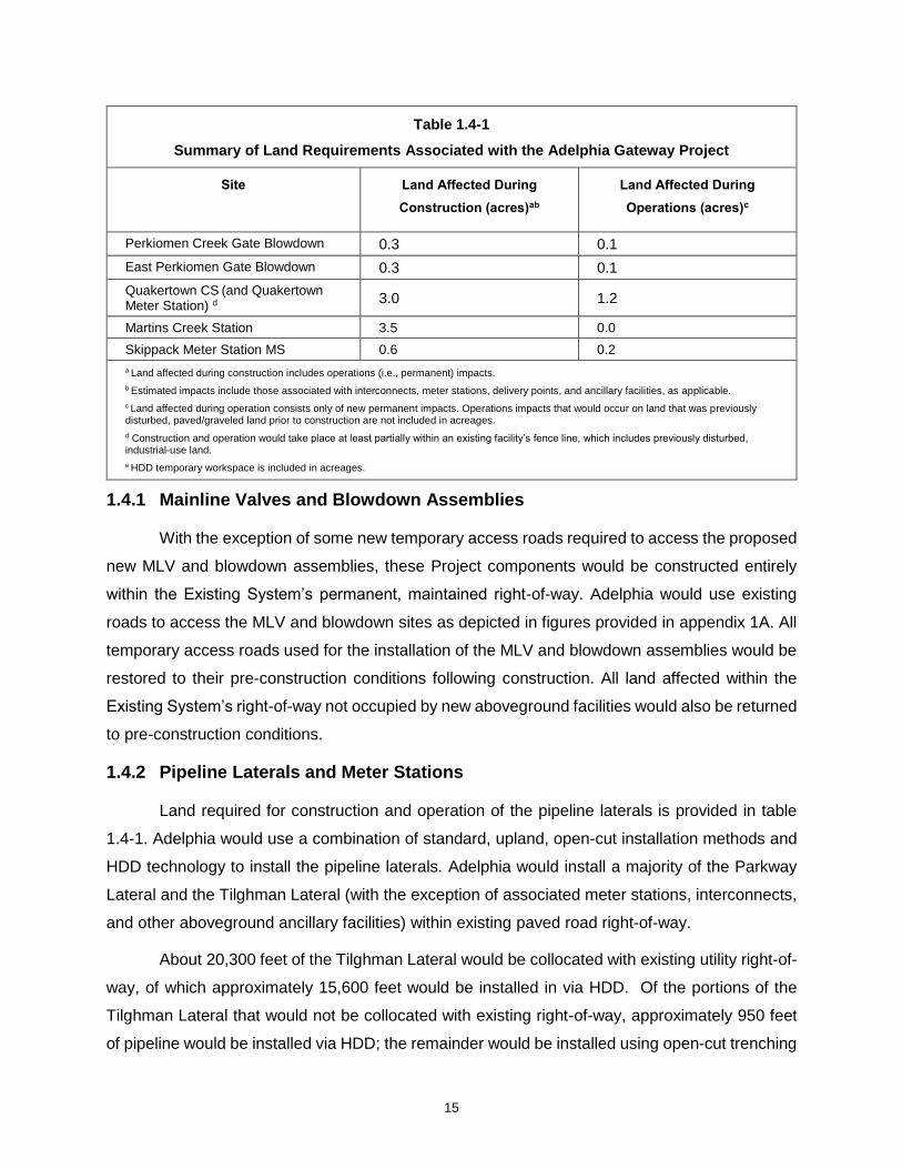
Table 1.4-1
Summary of Land Requirements Associated with the Adelphia Gateway Project
Site Land Affected During
Construction (acres)ab
Land Affected During
Operations (acres)c
Marcus Hook CS (and wareyard)d 0.7 0.0
Parkway Lateral (and Delmarva, TETCO, and TCO Meter Stations)d
1.6 0.8
Tilghman Lateral (and Transco, Monroe, and PECO Meter Stations)de
22.2 3.0
MLV Option 1 0.4 0.2
MLV Option 2 0.4 0.2
Chester Creek Gate Blowdown 0.7 0.5
Paoli Pike Gate Blowdown 0.2 0.0
Pickering Creek Gate Blowdown 0.6 0.4
French Creek Gate Blowdown 0.5 0.3
Cromby Gate Blowdown 1.2 1.0
Schuylkill River Gate Blowdown 2.7 2.5
15
Table 1.4-1
Summary of Land Requirements Associated with the Adelphia Gateway Project
Site Land Affected During
Construction (acres)ab
Land Affected During
Operations (acres)c
Perkiomen Creek Gate Blowdown 0.3 0.1
East Perkiomen Gate Blowdown 0.3 0.1
Quakertown CS (and Quakertown Meter Station) d
3.0 1.2
Martins Creek Station 3.5 0.0
Skippack Meter Station MS 0.6 0.2
a Land affected during construction includes operations (i.e., permanent) impacts.
b Estimated impacts include those associated with interconnects, meter stations, delivery points, and ancillary facilities, as applicable.
c Land affected during operation consists only of new permanent impacts. Operations impacts that would occur on land that was previously disturbed, paved/graveled land prior to construction are not included in acreages.
d Construction and operation would take place at least partially within an existing facility’s fence line, which includes previously disturbed, industrial-use land.
e HDD temporary workspace is included in acreages.
1.4.1 Mainline Valves and Blowdown Assemblies
With the exception of some new temporary access roads required to access the proposed
new MLV and blowdown assemblies, these Project components would be constructed entirely
within the Existing System’s permanent, maintained right-of-way. Adelphia would use existing
roads to access the MLV and blowdown sites as depicted in figures provided in appendix 1A. All
temporary access roads used for the installation of the MLV and blowdown assemblies would be
restored to their pre-construction conditions following construction. All land affected within the
Existing System’s right-of-way not occupied by new aboveground facilities would also be returned
to pre-construction conditions.
1.4.2 Pipeline Laterals and Meter Stations
Land required for construction and operation of the pipeline laterals is provided in table
1.4-1. Adelphia would use a combination of standard, upland, open-cut installation methods and
HDD technology to install the pipeline laterals. Adelphia would install a majority of the Parkway
Lateral and the Tilghman Lateral (with the exception of associated meter stations, interconnects,
and other aboveground ancillary facilities) within existing paved road right-of-way.
About 20,300 feet of the Tilghman Lateral would be collocated with existing utility right-of-
way, of which approximately 15,600 feet would be installed in via HDD. Of the portions of the
Tilghman Lateral that would not be collocated with existing right-of-way, approximately 950 feet
of pipeline would be installed via HDD; the remainder would be installed using open-cut trenching

16
and conventional techniques and would require surface easements. All temporary work space
(TWS) required to support various pipeline installation would be returned to preconstruction
conditions following completion of construction.
Adelphia anticipates that an approximate 40- to 45-foot-wide temporary construction
workspace corridor would be used within the road right-of-way easement for the Parkway Lateral
(see alignment drawings). Typical construction workspace for pipe installation would not extend
beyond the existing road rights-of-way, however select areas would require additional temporary
workspace (ATWS). All ATWS required to support various pipeline installation would be returned
to preconstruction conditions following completion of construction.
Resource Report 8 provides more detail on areas in which the Project would be collocated
with other existing rights-of-ways. Once the pipeline is installed, Adelphia would backfill the trench
with materials satisfactory to the governing entity of the road, and all affected roads would be
returned to their pre-construction conditions. Additional information about open-cut installation
methods is provided in section 1.5.
As additional field and civil surveys, landowner negotiations, agency consultations, and
engineering studies are performed, Adelphia will evaluate whether additional workspace to
construct the Laterals would be necessary to safely construct the pipeline in specific locations.
During the final design phase of the Project, any additional staging areas and work spaces not
identified at the time of the filing of this Application would be included as part of the Project study
area and incorporated into agency consultations, environmental permitting, and resource surveys
and filed accordingly on the FERC docket.
All temporarily impacted land used for construction of the pipeline laterals and meter
stations, including the Skippack Meter Station, would be returned to its pre-construction state (i.e.,
repaved, re-graveled, or re-graded and re-seeded). Operational areas for the meter stations
would be permanently converted to paved/graveled industrial-use land. Depictions of the pipeline
laterals and associated facilities and ATWS are included on drawings provided in appendix 1A,
and plot plans are provided in appendix 1B.
1.4.3 Aboveground Facilities
Land required for construction and operation of the proposed aboveground facilities is
summarized in table 1.4-1. Depictions of aboveground facilities are provided in appendix 1A. Plot
plans for compressor stations are provided in appendix 1B. Construction and operation of the
Marcus Hook CS and Martins Creek Station would occur entirely within previously disturbed,

17
paved/graveled, industrial-use land.
Construction of the Quakertown CS would require 1.2 acres of land, all of which is located
on previously disturbed, paved/graveled, industrial-use land within the boundaries of the existing
Quakertown M&R Station. Adelphia would lease an additional 1.8 acres of land also adjacent to
the Quakertown M&R Station for ATWS during construction. The ATWS would be returned to its
pre-construction conditions following construction. All other areas (1.2 acres) used for
Quakertown CS construction would be permanently covered with gravel for use during operations.
1.5 CONSTRUCTION PROCEDURES
1.5.1 Marking Workspace
Adelphia would notify affected landowners, including those associated with properties
adjacent to all areas where construction would take place in advance of construction activities.
Following these notifications, a survey crew would mark the limits of the proposed construction
workspace and access roads, property boundaries, underground utilities, and identified foreign
pipelines, as applicable. Adelphia would contact the applicable One-Call centers for Pennsylvania
and Delaware to accurately and safely identify and flag buried utility lines by their respective
owners. Previously identified sensitive resources, such as wetland boundaries, would also be
located and marked to minimize or avoid adverse impacts during construction. Temporary erosion
and sediment control devices would be installed at this time, as needed, in accordance with the
FERC Upland Erosion Control, Revegetation, and Maintenance Plan (FERC Plan) and Wetland
and Waterbody Construction and Mitigation Procedures (FERC Procedures).
1.5.2 Clearing and Grading
Following the establishment of workspace boundaries, the construction workspace would
be cleared and graded, where necessary, to create a level workspace to allow safe passage of
equipment. Clearing includes the removal of brush, trees, roots, and other obstructions. Non-
woody vegetation may be mowed to ground level. No cleared material would be placed within
wetland areas. Grading would include removing rock outcrops, tree stumps, ridges, and
topographic irregularities.
With the exception of in stream buffers and wetlands, tree stumps would be removed from
the permanent right-of-way. Stump grinding may be used as an alternative to removal to leave
below grade root systems intact to aid in soil stabilization. Cleared vegetation and debris within
the construction workspace would be disposed of in accordance with federal and state regulations
either by chipping and spreading, transportation to a commercial disposal facility, storing along
18
the right-of-way with landowner approval, or other approved methods. If material is chipped, the
chipped material not removed from the site may be spread across the upland areas of the
construction work space in a manner that would not inhibit revegetation or broadcast into areas
off right-of-way. Wood chips would not be left within agricultural lands, wetlands, or within 50 feet
of wetlands. Wood chips would not be stockpiled in a manner that they may be transported into a
wetland. Trees, if suitable, would be taken off-site by the clearing contractor and used for timber
unless the landowner has made alternative arrangements for the salvageable timber.
Temporary security fencing would be installed around the construction workspace, as
required, either during or immediately following clearing and grading activities to limit public
access. Adelphia would implement applicable soil mitigation procedures as outlined in the FERC
Plan and Procedures, such as segregating topsoil from subsoil and installing silt fence during and
immediately following clearing and grading activities, as needed.
1.5.2.1 Clean-up and Restoration
Following completion of construction of each proposed facility, temporary workspace not
covered with gravel or asphalt would be graded, restored, and reseeded. Previously
paved/graveled areas would be recovered with gravel or asphalt. Construction debris and organic
refuse unsuitable for distribution over the construction workspace would be disposed of at
appropriate facilities in accordance with applicable regulations. Permanent erosion control
devices would be installed as appropriate, and revegetation measures would be applied in
accordance with FERC Plan and Procedures and specific landowner requests.
1.5.3 Facility-specific Construction Procedures
1.5.3.1 Mainline Valve and Blowdown Assemblies
To install the new MLV and blowdown assemblies, Adelphia would clear, grade, and
excavate, as necessary, to access the existing pipeline. For the MLV, Adelphia would then cut
out an approximately 20-foot-long section of the pipe and replace that section with the new valve
assembly. For the blowdown assemblies, Adelphia would remove small sections of existing pipe
on either side of the existing MLV and install the blowdown assemblies in their place. Adelphia
would then backfill the excavated areas with the same material that was removed from the trench
and restore the areas to pre-construction conditions. Areas used for temporary access roads
would also be restored to pre-construction conditions following construction.

19
1.5.3.2 Pipeline Installations
Trenching
Once all construction workspace is marked off, cleared, and graded, Adelphia would begin
excavating the pipeline trench in the center of the construction right-of-way. Spoil from the ditch
would be placed within the Project right-of-way or collected in vehicles for temporary storage until
backfill activities begin.
The trench generally would be approximately 12 inches wider than the diameter of the
pipe and of sufficient depth to allow for the minimum cover requirements to the top of the pipe in
accordance with U.S. Department of Transportation (USDOT) regulations pursuant to the Natural
Gas Pipeline Safety Act of 1968, as amended. Crossing of foreign pipelines would generally
require the pipeline to be buried at greater depths depending upon the depth of the foreign
pipeline. Pipeline burial depths would comply with all applicable requirements.
Stringing
The stringing operation involves moving the pipe into position in proximity to the prepared
right-of-way. Pipe for laterals would be delivered to the Marcus Hook CS typically by truck and
would then be moved by truck to the construction zone, where it would be placed in proximity to
the right-of-way in preparation for subsequent lineup and welding operations. Individual joints of
pipe would be strung in proximity to the right-of-way parallel to the centerline and arranged so
they are easily accessible to construction personnel. Stringing activities would be coordinated
with the advance of the trenching or HDD activities to minimize potential impacts to resources.
Steel pipe sections or joints in standard 20- or 40-foot lengths would be used on the Project.
Integrity Inspection
Once the pipe is strung along the centerline, the ends would be carefully aligned and
welded together using multiple passes for a full penetration weld. Only welders qualified according
to applicable American Petroleum Institute Standard 1104 would be permitted to perform the
welding.
To ensure weld quality and integrity, the welds would be inspected both visually and non-
destructively using radiographic (x-ray) or another approved test method, in accordance with
American Petroleum Institute Standard 1104. Welds displaying defects would be repaired or
removed re-welded and re-inspected.
20
Bending
The pipe would be delivered to the Project site in straight sections. However, field bending
of the pipe may be required to allow the pipeline to follow grade changes and direction changes
of the right-of-way. For turns involving larger deflections and/or small radii, often related to spatial
limitations due to easement constraints, Adelphia would use prefabricated elbow fittings.
Welding and Coating
All welders and welding procedures would be qualified in accordance with USDOT
requirements (Title 49 CFR Part 192). All piping system welds would be verified by a non-
destructive testing method to ensure compliance with code requirements.
Once a weld has been inspected and approved, the welded area would be coated with
appropriate field joint system prior to burial.
Lowering-in and Backfill
The pipe lengths are lowered into the trench by specialty “side boom” tractors. Extreme
care is taken to protect the coating during the lowering-in process. Lowered pipe is positioned
within the trench on sandbag benches (or approved equivalent structures), or padding the trench
with screened subsoil; topsoil would not be used for padding. Connecting ends of the pipe would
be welded together in the ditch followed by the above inspection and coating process. Following
lowering-in, the trench and pipeline would be backfilled. A bedding layer of rock-free pad dirt
would be placed first to protect the pipe and coatings. Final backfill makes use of material
excavated from the trench; topsoil would not be used for backfill.
Horizontal Directional Drilling
The HDD construction method is a process by which a pipeline is installed beneath a given
feature. Typically, minimal surface disturbance occurs between the entry and exit points of the
HDD. The feasibility of using HDD and the length of pipeline that can be installed using this
method depends on factors such as access to the entry and exit points, subsurface conditions
(geology), entry and exit elevations, terrain, availability of workspace, and pipe diameter. Adelphia
anticipates that HDD technology would be used for a majority (approximately 80 percent) of the
Tilghman Lateral installation to minimize impacts to sensitive resources.
Open Cut Waterbody Crossings
Adelphia could use the open-cut method to cross Stoney Creek. Should this method be
selected, the full width of the construction right-of-way would be used on either side of the waterbody

21
for construction staging and pipeline fabrication. During clearing and grading activities, a temporary
bridge would be constructed across the waterbody to permit construction equipment to cross.
Construction equipment would be required to use the bridge, except the clearing crew who would
be allowed one pass through the waterbodies before the bridges are installed. Bridges and supports
would be removed after restoration is complete.
Clearing would involve the removal of trees and brush from the construction right-of-way and
temporary construction workspace. Woody vegetation would be cleared to the edge of the
waterbodies, but a 10-foot-long herbaceous strip would be left on the approaches until immediately
before construction to provide a natural sediment filter and minimize the potential for erosion
immediately adjacent to the waterbody. Initial grading of the herbaceous strip would be limited to the
extent needed to install a bridge and in areas that are needed to construct the pipeline safely where
large grade cuts are necessary.
During clearing where possible and during grading, sediment barriers would be installed and
maintained adjacent to the waterbody and within temporary construction workspaces, where
needed, to minimize the potential for sediment runoff. Drivable berms may be installed and
maintained across the right-of-way in lieu of silt fence or straw bales.
Flume Crossing Method
Adelphia may choose to cross Stoney Creek by using the flume crossing method (a dry
open cut crossing method). The flume crossing method involves diverting the flow of the stream
across the construction site through one or more flume pipes placed in the stream. The first step
in the flume crossing method involves placing a sufficient number of adequately sized flume pipes
in the stream to accommodate the highest anticipated flow during construction. After placing the
pipes in the stream, sand or pea gravel bags would be placed in the stream upstream and
downstream of the proposed trench. The bags serve to dam the stream and divert the stream flow
through the flume pipes, thereby isolating the stream flow from the construction area.
Backhoes located on both banks of the stream would excavate a trench under the flume
pipe in the isolated streambed. Spoil excavated from the stream trench would be placed or stored
a minimum of 10 feet from the edge of the waterbody or in ATWS as necessary. Once the trench
is excavated, a pre- fabricated segment of pipe would be installed beneath the flume pipes. The
trench would then be backfilled with native spoil from the streambed. If trench dewatering is
necessary near waterbodies, the trench water will be discharged into an energy
dissipation/sediment filtration device, such as geotextile filter bag or straw bale structure, away

22
from the water’s edge, preferably in a well-vegetated upland area to prevent heavily silt-laden
water from flowing into the waterbody.
Dam and Pump Crossing Method
Adelphia may choose to cross Stoney Creek by using the dam and pump crossing method
(a dry open cut crossing method). The dam and pump crossing method involves constructing
temporary sand or pea gravel bag dams upstream and downstream of the proposed crossing site
while using a high capacity pump to divert water from the upstream side around the construction
area to the downstream side. Energy dissipation devices, such as steel plates would be placed on
the downstream side at the discharge point to prevent streambed scour.
After installing the dams and commencing pumping, a portable pump (separate from that
pumping the stream flow around the construction area) may be used to pump standing water from
between the dams into a dewatering structure consisting of straw bales/silt fence or into a filter bag
located away from the stream banks, thereby creating a dry construction area.
Once the area between the dams is stable, backhoes located on both banks would excavate
a trench across the stream. Spoil excavated from the trench may be stored in the dry streambed
adjacent to the trench if the stream crossing is major or in a straw bale/silt fence containment area
located a minimum of 10 feet from the edge of the stream banks. Leakage from the dam, or
subsurface flow from below the streambed, may cause water to accumulate in the trench. As water
accumulates in the trench, it may be periodically pumped out and discharged into a dewatering
structure located away from the stream banks.
After trenching across the streambed is completed, a prefabricated segment of pipe would
be installed in the trench. The streambed portion of the trench is immediately backfilled with
streambed spoil. Once restoration of the streambed is complete, the dams are removed and normal
flow is re-established in the stream.
Completed stream crossings using the flume or dam and pump methods would be stabilized
before returning flow to the channel. Original streambed and bank contours would be re-established,
and mulch, jute thatching, or bonded fiber blankets will be installed on the stream banks. Where the
flume technique is used, stream banks would be stabilized before removing the flume pipes and
returning flow to the waterbody channel.
Seeding of disturbed stream approaches would be completed in accordance with the FERC
Plan and Procedures after final grading, weather and soil conditions permitting. Where necessary,
slope breakers would be installed adjacent to the stream’s banks to minimize the potential for

23
erosion. Sediment barriers, such as silt fence and/or straw bales would be maintained across the
right-of-way until permanent vegetation is established. Temporary equipment bridges would be
removed following construction.
Wet Open Cut Crossing Method
Adelphia could cross Stoney Creek by using the wet open cut crossing method. The wet
open cut construction method involves the excavation of the pipeline trench across the waterbody,
installation of a prefabricated pipeline segment, and backfilling of the trench with excavated material.
Depending upon the width of the crossing and the reach of the excavating equipment, excavation
and backfilling of the trench will generally be accomplished using backhoes or other excavation
equipment operating from one or both banks of the waterbody. Excavated material from the trench
would be placed on the bank above the ordinary high water mark for use as backfill. The pipe
segment can be weighted, as necessary to provide negative buoyancy and placed below scour
depth. Typical backfill cover requirements would be met, contours would be restored within the
waterbody, and the banks would be stabilized via seeding and/or the installation of erosion control
matting or riprap, per applicable agency approvals. One of the goals of open cut crossings is to
complete all in-stream construction (trenching, pipe installation, backfill, and streambed restoration)
within 24 hours.
Road Crossings
Construction of the Project across paved roads would be accomplished by boring under
the roadbed. Construction of the Project across unpaved roads would be accomplished by boring
under the roadbed or by open-cut methods. The boring method involves excavation of a bore pit
on one side of the crossing and a receiving pit on the other side. A boring machine then cuts a
shaft under the crossing using a cutting head mounted on an auger. The pipeline is then pushed
or pulled through the shaft.
The open-cut method of road crossing involves trenching across the road and then
restoring the road to pre-construction of better conditions following construction. If an open-cut
road requires and extensive construction duration, provisions would be made for detours or other
measures to permit traffic flow during construction. If necessary, traffic control measures would
be coordinated with the appropriate state or local agency with jurisdiction over the affected road.
The pipeline laterals would be installed at a minimum depth as required in Title 49 CFR
Part 192, USDOT requirements, or permit. All crossings would be designed to withstand
anticipated external loadings and installed at the calculated depth. Temporary work space areas
24
would be required at road crossings to accommodate extra spoil generated from the entrance and
exit pits at bored crossings or from the increased excavation depths at open-cut road crossings
as well as for staging of pipe and vehicle parking.
Hydrostatic Testing
Completed sections of pipeline would be further tested using water pressure. Pipes would
be filled with water and then pressurized to levels required to qualify the facilities for the desired
MAOP designated for the pipeline. Hydrostatic pressure testing would comply with USDOT
regulations specified in Title 49 CFR Part 192, ASME B31.8, and applicable state and local
regulations to verify mechanical integrity and to ensure that it can safely operate at the designated
MAOP. Additional information about hydrostatic testing and measures to protect water resources
are discussed in Resource Report 2 – Water Use and Quality.
1.5.3.3 Aboveground Facility Installations
For the proposed Marcus Hook CS and Quakertown CS, Adelphia would first clear, grade,
and excavate land, as necessary, to accommodate the reinforced concrete foundation that is
required for the new compressor unit and buildings. Forms would be set, rebar would be installed,
and concrete would be poured into the foundation setting. Concrete pours would be randomly
sampled to verify compliance with minimum strength requirements. Backfill would be compacted
in place, and excess soil would be used elsewhere or distributed around the site.
Once the concrete foundations have been completed and determined to meet the design
requirements, Adelphia would begin installing machinery and buildings for the compressor
stations. Various piping and electrical conduit systems would be connected once the machinery
is in place. Electrical wiring would be installed for power and instrumentation. Compression
equipment is typically shipped to the site by truck after construction commences. The
compressors would be offloaded, positioned on the foundation, leveled, grouted, and secured.
Compressor station utilities supporting the operation of the gas compressor and cooling
equipment would be housed in modularized, skid mounted buildings. Prior to placing the new
compressor units into service, Adelphia would develop and implement measures outlined in
Project-specific station commissioning plans to ensure the proper function of controls and safety
features.
New meter stations would be installed using generally accepted industry design and
construction standards. Minimal concrete foundations are required for electronic measurement
buildings and other ancillary facilities. Inlet/outlet meter and regulator headers would be installed

25
below ground with meters, flow control, regulators, and instrumentation installed above round for
ease in operation, maintenance, testing and calibration. Aboveground and below-ground piping
would be installed using the same welding and construction practices as pipeline laterals and
compressor stations, and be hydrostatically tested in accordance with all applicable regulations.
Adelphia and its contractors would park vehicles and equipment in designated areas at or near
the Project Sites that meet guidelines provided in its Spill Pollution, Prevention, and
Countermeasures Plan and the FERC Plan and Procedures to avoid potential impacts to sensitive
resources.
1.5.3.4 Ancillary Facility Installations
Pipe connections associated with the new compressors, and laterals would be flanged,
screwed, or welded. Pig launching and receiving facilities, with the appropriate valves and
equipment will be installed at each end of the pipeline laterals to allow pipeline to be pigged and
periodically inspected using inline electronic pigging devices. Additional ancillary equipment to be
installed as part of the project includes: filter separator vessels, liquid disposal tanks, valve
actuators, electronic monitoring instruments, electronic measurement equipment (RTUs), BTU
determination equipment, SCADA communications equipment and safety monitoring and shut
down systems.
1.5.3.5 Environmental Compliance, Training, and Inspection
To ensure that the construction of the proposed facilities would comply with FERC
Certificate conditions, the mitigation measures identified in the resource reports in this Application,
and the requirements of other federal and state permitting agencies designed to avoid and/or
minimize potential environmental impacts, Adelphia would include, whenever possible,
implementation details in its construction drawings and specifications. Adelphia’s selected
contractors would receive copies of design specifications, the FERC Plan and Procedures, and
applicable other environmental documents.
For mitigation measures that address pre-construction surveys and clearances, Adelphia
would provide pertinent correspondence and documentation to the construction contractor(s).
For those mitigation measures that address permit conditions from federal and state agencies,
Adelphia would provide copies of permits and related drawings. For those mitigation measures
that, in part, address post-construction requirements, Adelphia engineers would provide
instructions and documentation to Adelphia’s operating personnel following the completion of
the construction. Adelphia would require selected contractors to install facilities according to

26
Adelphia and USDOT specifications, specific permit conditions, and the terms of the negotiated
contract.
1.6 OPERATION AND MAINTENANCE
It is anticipated that the Project would result in the need for a total of seven to ten additional
operations employees for the two compressor stations. All Project facilities would be patrolled on
a routine basis and personnel well-qualified to perform both routine and extraordinary
maintenance on pipeline facilities would handle all maintenance. If necessary, permanent
structural controls would be installed and maintained to accomplish maximum stabilization,
prevent erosion and control sedimentation.
In accordance with USDOT requirements, Adelphia would follow routine operations and
maintenance procedures to ensure safe and reliable operation of Project facilities as further
described in Resource Report 11 – Reliability and Safety. Standard compressor and meter station
operation procedures include activities such as:
• calibration, maintenance, and inspection of equipment;
• pressure, temperature, and vibration data monitoring;
• landscape maintenance; and
• periodic checks of safety and emergency equipment and cathodic protection systems.
1.7 FUTURE PLANS AND ABANDONMENT
Because Adelphia would be a provider of natural gas transportation, it must remain
responsive to its customers’ needs for capacity. Hence, Adelphia would constantly evaluate its
customers’ needs and whether or not such needs can be met by existing infrastructure or whether
additional facilities are needed. Demand for transportation is dynamic and making long-term
predictions is speculative at best. Adelphia would continue to work with market participants to
develop expansions across its natural gas transmission systems to meet the demands of the
market. If additional demand for natural gas requires future expansion, Adelphia would seek the
appropriate authorizations from the FERC. When and if an Application is filed, the environmental
impact of the new proposed facilities would be examined. Adelphia does not anticipate a scenario
in which the Project, once constructed, would no longer be needed. However, in the event that
this would occur, Adelphia would follow all applicable regulatory requirements to decommission
the Project.

27
1.8 STAKEHOLDER OUTREACH
Adelphia has been, and will continue to, work with Project stakeholders throughout the
course of its Project in order to facilitate stakeholder communications, assist with early
identification and resolution of issues, and disseminate information regarding the Project.
Adelphia will continue to keep landowners, concerned citizens, government officials and
regulatory agencies informed about the Project developments, construction, and restoration
through various means such as: notification letters, local land agents, as well as website and local
contact.
Adelphia initiated public outreach in October 2017. Significant efforts have been made to
inform the public, particularly landowners and local, state, and federal officials, about the
proposed Project, including the creation of a Project website (www.Adelphiagateway.com),
personal visits, phone calls, emails, and written correspondence. The objective in implementing
a comprehensive stakeholder outreach strategy is to identify and potentially resolve issues raised
by stakeholders in a timely fashion.
Adelphia would notify all affected landowners pursuant to 18 CFR § 157.6(d) and provide
information regarding procedures to follow in the event that a landowner has any concerns or
problems during construction. Appendix 1E includes a list of landowners affected by the Project;
Adelphia requests that the information within this appendix remains privileged and confidential.
Throughout the course of the Project, landowners and other concerned citizens will be
kept informed about Project permitting developments, construction, and restoration through
written and verbal communications. Adelphia began talking to landowners about the scope and
construction schedule as early as the survey phase. Adelphia’s representatives provided the
landowner with a business card that has the agent’s email and cell phone number as well as the
local project office’s phone number and address. The representative would maintain contact with
the landowner into the construction phase and be available in the field to address landowner
concerns as they arise. Adelphia would notify affected landowners (i.e., those owning property on
which Adelphia obtained lease agreements for the pipeline laterals and those adjacent to the
facilities and those landowners crossed or impacted by access to the sites) prior to the start of
construction by written notification.
1.9 PERMITS AND APPROVALS
Adelphia will obtain applicable permits and approvals relating to its aboveground facilities
across or under roads, drainage facilities, waterbodies, wetlands, and through any other sites

28
where a governmental permit or approval is required. Table 1.9-1 provides a list of permits,
approvals, and consultations, and their applicable federal, state, and local agencies.
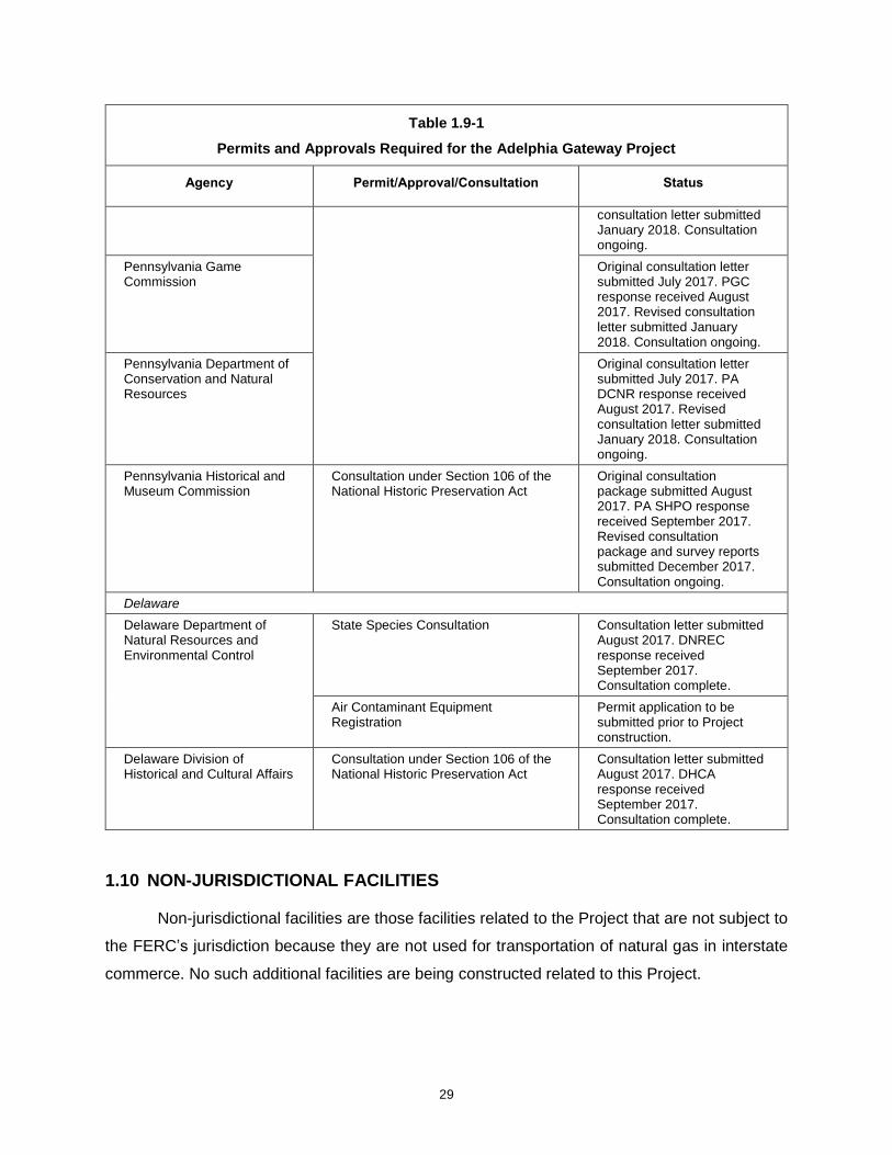
Table 1.9-1
Permits and Approvals Required for the Adelphia Gateway Project
Agency Permit/Approval/Consultation Status
Federal
FERC Certificate of Public Convenience and Necessity
Application filed January 2018. Application in review.
U.S. Fish and Wildlife Service, Pennsylvania Field Office
Consultation under Section 7 of the Endangered Species Act
Original consultation letter submitted July 2017. USFWS response received August 2017. Revised consultation letter submitted January 2018. Consultation ongoing.
Consultations under The Migratory Bird Treaty Act and The Bald and Golden Eagle Protection Act
Consultation letter submitted January 2018.
U.S. Army Corps of Engineers, Philadelphia District
Clean Water Act Section 404 authorization
General permit application, if necessary, to be submitted upon completion of surveys.
State
Pennsylvania Department of Environmental Protection
Water Obstruction and Encroachment Permit (in conjunction with the Section 404 authorization application under PA State Programmatic General Permit 5 (PASPGP-5))
General permit application, if necessary, to be submitted upon completion of surveys
Clean Water Act Section 401 Water Quality Certification
Application, if necessary, to be submitted in conjunction with the PASPGP-5 application)
Coastal Zone Management Area Consistency Determination
Consistency Determination review form submitted January 2018.
Erosion and Sediment Control General Permit-2 for Earth Disturbance Associated with Oil and Gas Activities (ESCGP-2)
To be submitted prior to Project construction.
National Pollutant Discharge Elimination System General Permit for Discharges for Hydrostatic Testing of Tanks and Pipelines (PAG-10)
To be submitted prior to Project construction.
Air Quality Permit Permit application to be submitted prior to Project construction.
Pennsylvania Department of Transportation
Highway Occupancy Permit Permit application to be submitted prior to Project construction.
Pennsylvania Fish and Boat Commission
State Species Consultation Original consultation letter submitted July 2017. PFBC response received September 2017. Revised
29
Table 1.9-1
Permits and Approvals Required for the Adelphia Gateway Project
Agency Permit/Approval/Consultation Status
consultation letter submitted January 2018. Consultation ongoing.
Pennsylvania Game Commission
Original consultation letter submitted July 2017. PGC response received August 2017. Revised consultation letter submitted January 2018. Consultation ongoing.
Pennsylvania Department of Conservation and Natural Resources
Original consultation letter submitted July 2017. PA DCNR response received August 2017. Revised consultation letter submitted January 2018. Consultation ongoing.
Pennsylvania Historical and Museum Commission
Consultation under Section 106 of the National Historic Preservation Act
Original consultation package submitted August 2017. PA SHPO response received September 2017. Revised consultation package and survey reports submitted December 2017. Consultation ongoing.
Delaware
Delaware Department of Natural Resources and Environmental Control
State Species Consultation Consultation letter submitted August 2017. DNREC response received September 2017. Consultation complete.
Air Contaminant Equipment Registration
Permit application to be submitted prior to Project construction.
Delaware Division of Historical and Cultural Affairs
Consultation under Section 106 of the National Historic Preservation Act
Consultation letter submitted August 2017. DHCA response received September 2017. Consultation complete.
1.10 NON-JURISDICTIONAL FACILITIES
Non-jurisdictional facilities are those facilities related to the Project that are not subject to
the FERC’s jurisdiction because they are not used for transportation of natural gas in interstate
commerce. No such additional facilities are being constructed related to this Project.

30
1.11 CUMULATIVE IMPACTS
Cumulative impacts may result when impacts from the construction and operation of the
Project are combined with the impacts from other past, present, and reasonably foreseeable
future actions, regardless of what agency (federal or non-federal) or person undertakes those
actions. In order to review potential cumulative impacts, Adelphia considered recently completed
(up to one year prior to construction of the Project), current, and reasonably foreseeable future
projects and other human-related activities that may also affect areas that would be affected by
the Project. Cumulative impacts are discussed by proximity in section 1.11.1 and on a resource-
by-resource basis in section 1.11.2.
1.11.1 Projects and Activities Considered
For the purposes of the cumulative impacts analysis and in order to identify small land
developments in proximity to the Project, Adelphia contacted county planning commissions and
reviewed local and state online sources to identify projects with ongoing impacts or projects that
have reasonably foreseeable past, present, or future actions that may have impacts on same
affected environments as the Project (New Castle County Land Use Department, 2017; Bucks
County Planning Commission, 2017; Lower Chichester Township, 2017; Delaware County
Planning Department, 2017). Records of correspondence are provided in appendix 1D. Adelphia
reviewed Delaware County Planning Commission (Delaware County planning Commission, 2017)
agenda records to determine all projects that have been proposed in proximity to the Marcus
Hook CS, wareyard, and the Parkway and Tilghman Laterals and associated M&R facilities, and
corresponded with the Bucks County Planning Commission (Bucks County Planning
Commission, 2017) to determine any potential projects in proximity to the Quakertown CS and
associated M&R facilities.
Adelphia is in the process of identifying whether there are any projects or activities
associated with the Martins Creek Station, the Skippack Station, the new MLV locations, and the
eight blowdown assembly locations that have the potential to result in cumulative impacts.
Activities at the Martins Creek Station would be limited to fence installation, which would occur
within existing industrial facilities. Ground disturbance would be short-term and limited to that
required to install fence posts and would not have the potential to significantly affect storm-water
within the facility. No habitat would be affected by fence installation and no archaeological surveys
or aboveground investigations for cultural resources were required by the Pennsylvania State
Historic Preservation Office (see Resource Report 4). The addition of the fence would not
significantly affect the view shed in the area as the proposed fence at Martins Creek Station would

31
be located within the existing Martins Creek Terminal. The fence installation would not generate
a significant amount of noise, and work would be short term.
Additionally, Adelphia proposes to construct one new MLV and conduct modifications to
add blowdown assemblies at eight existing MLV sites. As discussed above, the work associated
with the new MLV construction and existing MLV modifications would be minor and would occur
within the maintained, previously disturbed right-of-way. Work would be short-term and through
application of the measures provided in the plans and procedures would not significantly affect
nearby resources or add to cumulative impacts on resources in the area. Although Adelphia
anticipates that the work at these Project facilities would not contribute to cumulative impacts,
Adelphia will supplement this cumulative impacts analysis for these Project facilities once records
are received from the respective planning commissions and other third-party sources.
Adelphia also conducted a search for larger projects, such as road, railway, electrical
transmission, FERC jurisdictional and non-jurisdictional linear pipeline projects, commercial or
residential developments, and other major industrial facilities that would be located within the
environment that would be affected by the Project (or have the potential to affect the same
resources as the Project). The various projects identified during Adelphia’s various searches are
discussed below.
1.11.1.1 Other Projects
Adelphia reviewed the PADEP’s Pennsylvania Pipeline Portal to determine other
proposed pipeline projects that may be in proximity to the Project (PADEP, 2017). Sunoco, LP’s
Mariner East II Project is located to the north of the Project and would terminate in Upper
Chichester, Pennsylvania. The Mariner East II Project would be located within the same HUC 10
watershed as the Project. Its nearest point to the Project would be more than one mile from the
Tilghman Lateral, where it joins the existing Mariner East I Project. The remaining portions of the
Mariner East I Project are located in areas also more than one mile away from the proposed
Adelphia Gateway Project. Construction of the Mariner East II Project has started, and it is
expected to be complete and in-service by the second quarter of 2018 (Sunoco, 2018). Therefore,
construction of the Adelphia Gateway Project and the Mariner East II Project would not occur at
the same time.
The PennEast Pipeline has been proposed by the PennEast Pipeline Company, LLC and
is a FERC jurisdictional project proposed to transport natural gas from Luzerne County, PA to
Mercer County, NJ. The proposed project would cross the existing 18-inch and 20-inch pipelines

32
and would be located within the HUC 10 watersheds that would also be occupied by the Project
facilities. The PennEast Pipeline filed with the FERC in 2015 and the final FERC EIS was issued
in April 2017. Construction of the PennEast Pipeline Project and the Adelphia Gateway Project
are not expected to occur at the same time.
The Adelphia Gateway Project may be in proximity to the potential Enbridge Greater
Philadelphia Expansion Project and might result in for cumulative impacts to occur if both of the
Projects are constructed. The Greater Philadelphia Expansion Project held an open season from
March 25, 2015 to May 8, 2015, but as of December 2017, the project is still in development, and
no construction has taken place. The Greater Philadelphia Expansion Project is estimated to be
completed in 2019, but because the project has not commenced pre-filing or any other filing with
FERC, Adelphia has determined that it is not reasonably foreseeable and has not considered any
impact of such project as cumulative with the Project.
The Marcellus to Market Project would be located within Chester County and involves
modification at an existing compressor station and two meter stations. The majority of this project
is located outside of the HUC 10 watersheds crossed by the proposed Adelphia Gateway Project.
However, some of the blowdown assemblies would be located in the same HUC 10 watershed
as would a portion (i.e., one of the meter stations) of the Marcellus to Market Project. The target
in-service date for this project was cited as November 2017, but the Chester County Planning
Commission indicates that the environmental report for the Project is still being prepared.
Because the Marcellus to Market Project is limited to modification at existing facilities it is unlikely
to add to cumulative impacts in the Project area.
Adelphia reviewed the Pennsylvania Department of Transportation’s Road and Bridge
Project Construction Mapper to determine any major road construction Projects in proximity to the
Project. Adelphia identified one project, the Market St. Over AMTRAK© Bridge Replacement
Project, which would occur approximately 0.2 mile away and is planned to be completed by
September 2019. The Bridge Replacement Project would replace an existing bridge over existing
railroad tracks (PennDOT, 2017). Cumulative impacts would be limited to potential noise and
traffic impacts during construction of the Projects.
Adelphia corresponded with county planning commissions and reviewed county planning
commission publications and records in order to determine potential land development within
proximity to the Project. Adelphia’s review identified several proposed land developments within
0.5 mile of the Project, including the Parkway and Tilghman Laterals (and associated meter
stations), the Marcus Hook CS and wareyard, and the Quakertown CS and Meter Station. These
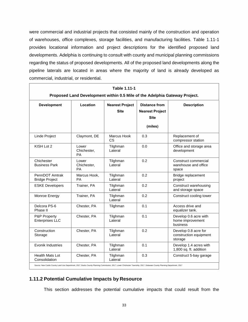
33
were commercial and industrial projects that consisted mainly of the construction and operation
of warehouses, office complexes, storage facilities, and manufacturing facilities. Table 1.11-1
provides locational information and project descriptions for the identified proposed land
developments. Adelphia is continuing to consult with county and municipal planning commissions
regarding the status of proposed developments. All of the proposed land developments along the
pipeline laterals are located in areas where the majority of land is already developed as
commercial, industrial, or residential.
Table 1.11-1
Proposed Land Development within 0.5 Mile of the Adelphia Gateway Project.
Development Location Nearest Project
Site
Distance from
Nearest Project
Site
(miles)
Description
Linde Project Claymont, DE Marcus Hook CS
0.3 Replacement of compressor station
KISH Lot 2 Lower Chichester, PA
Tilghman Lateral
0.0 Office and storage area development
Chichester Business Park
Lower Chichester, PA
Tilghman Lateral
0.2 Construct commercial warehouse and office space
PennDOT Amtrak Bridge Project
Marcus Hook, PA
Tilghman Lateral
0.2 Bridge replacement project
ESKE Developers Trainer, PA Tilghman Lateral
0.2 Construct warehousing and storage space
Monroe Energy Trainer, PA Tilghman Lateral
0.2 Construct cooling tower
Delcora PS-6 Phase II
Chester, PA Tilghman 0.1 Access drive and equalizer tank.
P&P Property Enterprises LLC
Chester, PA Tilghman Lateral
0.1 Develop 0.6 acre with home improvement business
Construction Storage
Chester, PA Tilghman Lateral
0.2 Develop 0.8 acre for construction equipment storage
Evonik Industries Chester, PA Tilghman Lateral
0.1 Develop 1.4 acres with 1,800 sq. ft. addition
Health Mats Lot Consolidation
Chester, PA Tilghman Lateral
0.3 Construct 5-bay garage
Source: New Castle County Land Use Department, 2017; Bucks County Planning Commission, 2017; Lower Chichester Township, 2017; Delaware County Planning Department, 2017
1.11.2 Potential Cumulative Impacts by Resource
This section addresses the potential cumulative impacts that could result from the

34
proposed Project and those projects identified in section 1.11.1 that are located within the
cumulative impact area defined for each resource.
1.11.2.1 Water Use and Quality
Cumulative impacts in regards to groundwater resources would not be significant,
because Adelphia would not withdraw groundwater for use in construction or operation of the
Project. Impacts on groundwater would be limited to the potential temporary and minor lowering
of groundwater levels due to trench dewatering (if necessary) and minor temporary increases in
turbidity following trench excavation (if the groundwater table is intercepted).
The evaluation of potential cumulative impacts on surface waters that would be affected
by the Project included consideration of large development projects such as other pipeline or
road projects within the HUC 10 watersheds and also smaller projects in proximity to the
waterbodies that would be crossed by the Project. The Project would be located within Raccoon
Creek-Delaware River, Tohickon Creek – Delaware River, and Upper Delaware River HUC 10
watersheds. The Mariner East II Project, Marcellus to Market Project, and the PennEast Pipeline
are the only major projects within a HUC-10 watershed that would also be occupied by the
Project. While these projects would be within the same watersheds, they would not cross any
waterbodies that would be affected by the Adelphia Gateway Project. The Marcellus to Market
Project would be limited to modifications at existing facilities.
Recent or ongoing construction and land development within proximity to the Project
could cause a period of time where soils may be exposed for an extended duration as a result
of incomplete revegetation. Exposed soils are more likely to erode and could result in increased
sedimentation in surface waterbodies. Adelphia would comply with the provisions provided in
the FERC Plan and Procedures regarding restoration and revegetation of disturbed areas.
Additionally, because one and potentially both Project waterbody crossings would be
accomplished by HDD, cumulative impacts to surface waters are not expected to occur.
1.11.2.2 Fish, Wildlife, and Vegetation
Adelphia used the same HUC-10 watershed evaluation area that was used to consider
potential cumulative impacts on surface water resources to evaluate cumulative impacts on
fisheries (see section 1.11.2.1). As such, cumulative impacts on fisheries would be similar to the
surface water resources impacts above; no cumulative impacts on fisheries are expected to occur
as a result of the Project.

35
Projects located within the HUC 10 watersheds that Project would be located in were
evaluated for potential cumulative impacts on wildlife and vegetation. As stated above, the only
major projects in relative proximity to the Project would be the Mariner East II Project, PennEast
Pipeline, and Marcellus to Market Project. The PennEast Pipeline and Mariner East II Projects
would require vegetation removal, land grading, and excavation, all of which directly impact
vegetation and wildlife resources. However, the impact associated with the construction of the
Project would be temporary, and land would be returned to pre-construction conditions following
construction. Further, the areas in which these activities would be occurring are well developed
industrial and residential areas that contain little to no prime wildlife habitat or vegetative
resources. Large portions of the Project would be constructed via HDD and Adelphia would not
maintain a permanent right-of-way in these areas limiting impacts on vegetation and habitat. The
Project is subject to Section 7 of the Endangered Species Act, and as such, Adelphia has
conducted and is continuing to conduct consultations with the U.S. Fish and Wildlife Service
(USFWS) regarding any potential impacts on threatened and endangered species. Any potential
impacts to listed species would be avoided, minimized, and or mitigated. For these reasons
combined cumulative impacts on vegetation and wildlife would be negligible and would not
significantly add to cumulative impacts on fish, wildlife, and vegetation within the Project area.
1.11.2.3 Cultural Resources
Adelphia reviewed the potential for cumulative impacts on cultural resources within 0.25
mile of the Project. The PennEast Pipeline would be located within 0.25 mile of the existing 18-
inch and 20-inch pipeline. Adelphia is continuing to consult with both State Historic Preservation
Offices (SHPO) regarding the Project. Adelphia has followed the SHPOs recommendations
regarding surveys and avoidance of cultural resources and would continue to follow the SHPOs
recommendations regarding surveys and protection of cultural resources. Since Adelphia would
adhere to the SHPO recommendations regarding required investigation and avoidance of cultural
resources the Project would not significantly add to cumulative impacts on cultural resources in
the area.
1.11.2.4 Socioeconomics
Cumulative impacts on socioeconomics were considered on a county-by-county basis
including Delaware, Montgomery, and Bucks counties in Pennsylvania and New Castle County in
Delaware. No more than ten long-term employees would be hired to operate the Project, and up
to 150 temporary workers who would be employed to construct the Project. Construction of the
Mariner East II Project is not expected to overlap with construction of the Project. The PennEast

36
Pipeline is currently obtaining state permits and awaiting approval from the FERC and is also not
expected to overlap with construction of the Project. The other land developments identified are
small in nature and are not likely to have significant impact on employment within the Project area.
Therefore, the Adelphia Gateway Project would not cause significant cumulative impacts on
workforce, local spending and tax income, or available temporary living quarters.
The addition of traffic on local roadways associated with construction personnel
commuting to and from the Adelphia Gateway Project construction work areas could also
contribute to cumulative regional traffic congestion. However, any contribution by the Project to
cumulative traffic impacts are expected to be temporary and short term. If construction on other
projects occurs concurrently, the cumulative impact on traffic patterns could lead to congestion in
localized areas.
1.11.2.5 Geological and Soil Resources
Adelphia reviewed potential cumulative impacts on geologic resource within a 0.25-mile
area of the Project workspaces. As discussed in Resource Report 6 (Geological Resources), the
majority of impacts would be temporary due to construction of the Project. Adelphia would restore
areas disturbed during construction to pre-construction contours to the extent practicable except
at aboveground facility locations which would be permanently maintained as industrial facilities.
Permanent impacts on topography would occur as result of the permanent aboveground facilities
that are part of the Project.
Adelphia reviewed the potential for cumulative soil impacts on soils within 0.25 mile of the
Project workspaces. Project impacts to soils could include increased susceptibility to erosion,
revegetation issues, disturbance of prime farmlands, and soil compaction due to the movement
of heavy equipment (see Resource Report 7 – Soil Resources). Adelphia would adhere to the
FERC Plan to minimize potential adverse effects on soils due to construction of its Project.
Adelphia would also develop and submit for approval to the PADEP site-specific Erosion and
Sediment Control Plans prior to the start of construction in order to prevent erosion and
sedimentation of soils during construction, conduct topsoil segregation in residential and
agricultural areas, and conduct compaction testing and where necessary soil compaction. A large
portion of the Project would be constructed via HDD and therefore further minimizing any potential
impacts on soils.
The Project’s effect on geology and soils would be highly localized and primarily limited to
the construction period. Cumulative impacts would only occur if other projects are constructed
37
during the Adelphia Gateway Project’s construction period in a shared location. Given this
constraint and when also considering the minimal impacts on soils and geology that would occur
as a result of the Adelphia Gateway Project, cumulative impacts on soil and geology resources
are expected to be minimal.
1.11.2.6 Land Use, Recreation, and Aesthetics
The area evaluated for land use cumulative impacts included projects and land
development located within the HUC 10 watershed where the Project would be located. The
Marcellus to Market Project would consist of modifications to existing facilities and would not
significantly affect land use within the watershed. However, the PennEast Pipeline and the
Mariner East II Projects would have an effect on land use. The remaining land that would be
affected by construction of the Project would be restored to preconstruction conditions. When
compared to other development within the Project area and the industrial and urban nature of the
surrounding area impacts on land use due to the Project would be minimal. The Project has
utilized existing industrial facilities to the extent possible to reduce conversion of open land and
forest land to industrial use. Additionally, large portion of the Project would be constructed via
HDD and therefore further minimizing effects on land use. The Project would not significantly
contribute to the cumulative impacts on land use as the majority of the area that would be affected
is already developed industrial and residential land located along an existing pipeline corridor,
and land development projects in proximity to the Project are all relatively minor and within
industrialized areas.
1.11.2.7 Air Quality
Construction-Related Air Emissions
Air emissions would result from the construction of the various Project components (e.g.,
compressor stations, meters stations, and pipeline laterals). Specifically, the use of heavy
equipment that are reliant on diesel-fired engines, increased on-road and off-road vehicle traffic,
earthmoving and stockpiling, would all result in air emissions. However, as outlined in section
9.1.5, Adelphia would implement various mitigation measures to minimize construction-related air
emissions. Furthermore, any such emissions, as quantified in appendix 9-C, would be short-term
and spread among the counties in which the Project would occur. Construction emissions
resulting from two of the more significant projects in the area, Mariner East II and PennEast
Pipeline, would not be foreseen to overlap with the Adelphia Project construction emissions since
1) Penn East is expected to be operational prior to commencement of Project construction, and
38
2) the Mariner East II was expected to be operational, however a revised schedule for that project
is not known due to ongoing litigation and compliance considerations. As such no cumulative
impact from construction emissions resulting the projects would be expected. Furthermore, given
the lack of other significant projects in the area with likely impacts on construction-related air
emissions, any cumulative air impact in the area would be minimal.
Long-Term (Operational) Air Emissions
Adelphia considered projects located within the counties in which the proposed Marcus
Hook CS and Quakertown CS would be located (Delaware and Bucks Counties, Pennsylvania;
both of which are part of the Metropolitan Philadelphia Interstate Air Quality Control Region) or
within 1.5 miles of the proposed compressor stations for air quality cumulative impact analysis.
Adelphia is in the process of expanding this analysis to encompass major sources of air emissions
within a 50 kilometer radius around the compressor stations and will provide a supplement once
the information has been made available from agency and other records. Any emissions
associated with the Project’s meter stations would be insignificant and are therefore not expected
to affect impacts to air quality. Additionally, operational impacts from the operation of the mainline
valve and blowdown assemblies are only expected to occur one time per year, on average, in the
event of pre-planned maintenance or emergency situations. As such, these activities are not
considered part of the normal operation of the Project and would not be expected to contribute to
a cumulative impact to air quality. Table 1.11-2 presents projects identified near the Marcus Hook
CS and addresses the potential for cumulative air quality impacts.
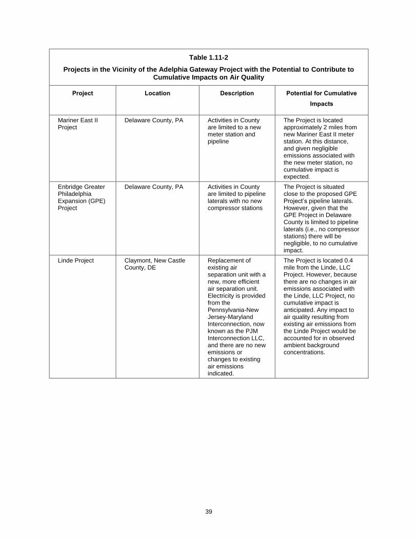
39
Table 1.11-2
Projects in the Vicinity of the Adelphia Gateway Project with the Potential to Contribute to Cumulative Impacts on Air Quality
Project Location Description Potential for Cumulative
Impacts
Mariner East II Project
Delaware County, PA Activities in County are limited to a new meter station and pipeline
The Project is located approximately 2 miles from new Mariner East II meter station. At this distance, and given negligible emissions associated with the new meter station, no cumulative impact is expected.
Enbridge Greater Philadelphia Expansion (GPE) Project
Delaware County, PA Activities in County are limited to pipeline laterals with no new compressor stations
The Project is situated close to the proposed GPE Project’s pipeline laterals. However, given that the GPE Project in Delaware County is limited to pipeline laterals (i.e., no compressor stations) there will be negligible, to no cumulative impact.
Linde Project Claymont, New Castle County, DE
Replacement of existing air separation unit with a new, more efficient air separation unit. Electricity is provided from the Pennsylvania-New Jersey-Maryland Interconnection, now known as the PJM Interconnection LLC, and there are no new emissions or changes to existing air emissions indicated.
The Project is located 0.4 mile from the Linde, LLC Project. However, because there are no changes in air emissions associated with the Linde, LLC Project, no cumulative impact is anticipated. Any impact to air quality resulting from existing air emissions from the Linde Project would be accounted for in observed ambient background concentrations.

40
Sunoco, multiple projects
Marcus Hook, Delaware County, PA
Multiple projects have been authorized via PADEP Plan Approvals over the past three years. Most recently this includes installation of cryogenic propane and ethane storage and offloading facilities.
Emissions increases from these and other recent projects at Sunoco have primarily been limited to VOCs, which are treated as a precursor to ozone. Ozone is a regional scale pollutant and tends to form downwind of the sources of precursor emissions. All recent Sunoco Partners projects have required minor source permitting without triggering a New Source Review. Given the magnitude of emissions from the Sunoco projects and the proposed Marcus Hook CS, cumulative air impacts are expected to be minimal.
Agilyx Corporation Project
Marcus Hook, Delaware County, PA
Installation of a new plastic-to-oil manufacturing facility
The Project would be located 1.3 miles from the Agilyx Corporation Project. The Agilyx Site is a natural minor facility with respect to air permitting authorization for construction and operation. Given this classification, cumulative air impacts are not anticipated.
Sources: Sunoco Pipeline, L.P., 2017; Spectra Energy, 2017; Linde, LLC, 2017; Energy Transfer, 2017; PA Bulletin, 47 Pa.B. 223, 2017; PA Bulletin, 46 Pa.B. 1909, 2016; PA Bulletin, 45 Pa.B. 7299, 2015; PA Bulletin, 45 Pa.B. 7178, 2015
No new projects were identified within 1.5 miles of the proposed Quakertown CS, and
there are no existing industrial sources of air emissions in proximity of the Compressor Station.
The closest projects identified are Cleveland Steel’s application for a new printing press via an
Air Quality General Permit, which would be 2.8 miles away; (PA Bulletin, 46 Pa. B 763, Feb. 13,
2016); Naceville Materials’ proposed installation of diesel fired engines and a portable non-
metallic mineral processing plant via Air Quality General Permits, which would be 3.7 miles
away(PA Bulletin, 46 Pa. B 467, June. 17, 20170; and a new animal crematorium, Abby Glen Pet
Memorial, authorized via an Air Quality General Permit, which would be 3.7 miles away (PA
Bulletin, 47 Pa. B 3375, June. 17, 2017). Model-estimated maximum ground level concentrations
resulting from operation of the Quakertown CS (see Resource Report 9) are predicted to occur at
the source boundary line. Given the distances from these projects to the Quakertown CS (and its
boundary line) and considering that all projects, including the Quakertown CS, are minor, no air
quality cumulative impact is anticipated.

41
1.11.2.8 Climate Change
Climate change is the adjustment of climate over time, whether due to natural variability
or as a result of human activity. Climate change cannot be represented by single annual events
or individual anomalies. The Intergovernmental Panel on Climate Change is the leading
international, multi-governmental scientific body for the assessment of climate change. The
United States is a member of the Intergovernmental Panel on Climate Change and participates
in working groups to develop reports. The leading U.S. scientific body on climate change is the
U.S. Global Change Research Program (“USGCRP”). The Intergovernmental Panel on Climate
Change and USGCRP have recognized the following:
• globally, greenhouse gases (GHG) have been accumulating in the atmosphere since the beginning of the industrial era (circa 1750);
• combustion of fossil fuels (coal, petroleum, and natural gas), combined with agriculture and clearing of forests, is primarily responsible for the accumulation of GHG;
• anthropogenic GHG emissions are the primary contributing factor to climate change; and
• impacts extend beyond atmospheric climate change alone and include changes to water resources, transportation, agriculture, ecosystems, and human health.
In May 2014, the USGCRP issued a report, Climate Change Impacts in the United States,
summarizing the impacts that climate change has already had on the United States and what
projected impacts climate change may have in the future (USGCRP 2014). The report includes
a breakdown of overall impacts by resource and impacts described for various geographic regions
of the country. The USGCRP and other international bodies have recognized that climate change
is currently happening. The United States and the world are warming, global sea level is rising,
and some types of extreme weather events are becoming more frequent and more severe. These
changes have already resulted in a wide range of impacts across every region of the country.
Impacts extend beyond atmospheric changes alone and affect water resources, transportation,
agriculture, ecosystems, and human health. These changes are thought to be driven primarily by
the accumulation of GHG in the atmosphere from the combustion of fossil fuels.
The USGCRP’s report notes the following observations of environmental impacts that may
be attributed to climate change in the Northeast region:
• average temperatures have risen about 2°F between 1895 and 2011 and are projected to increase another 1 to 8°F over the next several decades with more frequent days above 90°F;

42
• areas that currently experience ozone pollution problems are projected to experience an increase in the number of days that fail to meet the federal air quality standards;
• an increase in health risks and costs for vulnerable populations due to projected additional heat stress and poor air quality;
• precipitation has increased by about 5 inches and winter precipitation is projected to increase 5 to 20 percent by the end of the century;
• extreme/heavy precipitation events have increased more than 70 percent between 1958 and 2010 and are projected to continue to increase;
• sea levels have risen about 1 foot since 1900 and are projected to continue increasing 1 to 4 feet by 2100 stressing infrastructure (e.g. communications, energy, transportation, water and wastewater);
• severe flooding due to sea-level rise and heavy downpours is likely to occur more frequently;
• crop damage from intense precipitation events, delays in crop plantings and harvest, and heat stress negatively affect crop yields;
• invasive weeds are projected to become more aggressive due to their benefit of higher CO2 levels;
• a change in range, elevation, and intra-annual life cycle events of vegetation and wildlife species; and
• an increase in carrier habitat and human exposure to vector-borne diseases (e.g. Lyme disease or West Nile).
As discussed in Resource Report 9, construction of the Project is expected to contribute
about 13,000 tons of GHG to the atmosphere over the one-year construction period. Operation
of the Project is estimated to contribute about 63,000 tons per year of GHG to the atmosphere.
The emissions are small in comparison; for example, in 2016, United States GHG emissions were
estimated to be 3,285 million tons per year. Note that these comparisons provide a frame of
reference for the general magnitude of GHG emissions, and are not an indicator of significance.
The Project purpose is to provide customers in the greater Philadelphia region with a
needed, new source of clean, safe, low-cost supply of natural gas. The Project would involve the
installation of two new compressor stations along an existing pipeline. Each new compressor
station would consist of 5,625 HP of compression. The resulting new compression would allow
for transport of an additional 250,000 dekatherms per day of natural gas along the pipeline
system. The Southern Segment of the pipeline, which is being converted to natural gas service,
would be where additional end use occurs as no additional natural gas would be projected for the
Northern Segment. The new natural gas would be transported to the downstream interstate
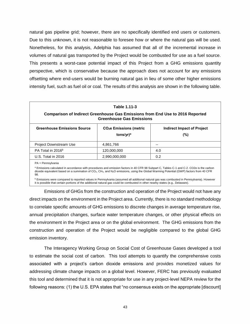
43
natural gas pipeline grid; however, there are no specifically identified end users or customers.
Due to this unknown, it is not reasonable to foresee how or where the natural gas will be used.
Nonetheless, for this analysis, Adelphia has assumed that all of the incremental increase in
volumes of natural gas transported by the Project would be combusted for use as a fuel source.
This presents a worst-case potential impact of this Project from a GHG emissions quantity
perspective, which is conservative because the approach does not account for any emissions
offsetting where end-users would be burning natural gas in lieu of some other higher emissions
intensity fuel, such as fuel oil or coal. The results of this analysis are shown in the following table.
Table 1.11-3
Comparison of Indirect Greenhouse Gas Emissions from End Use to 2016 Reported Greenhouse Gas Emissions
Greenhouse Emissions Source CO2e Emissions (metric
tons/yr)a
Indirect Impact of Project
(%)
Project Downstream Use 4,861,766 --
PA Total in 2016b 120,000,000 4.0
U.S. Total in 2016 2,990,000,000 0.2
PA = Pennsylvania
a Emissions calculated in accordance with procedures and emission factors in 40 CFR 98 Subpart C, Tables C-1 and C-2. CO2e is the carbon dioxide equivalent based on a summation of CO2, CH4, and N2O emissions, using the Global Warming Potential (GWP) factors from 40 CFR 98.
b Emissions were compared to reported values in Pennsylvania (assumed all additional natural gas was combusted in Pennsylvania). However it is possible that certain portions of the additional natural gas could be combusted in other nearby states (e.g., Delaware).
Emissions of GHGs from the construction and operation of the Project would not have any
direct impacts on the environment in the Project area. Currently, there is no standard methodology
to correlate specific amounts of GHG emissions to discrete changes in average temperature rise,
annual precipitation changes, surface water temperature changes, or other physical effects on
the environment in the Project area or on the global environment. The GHG emissions from the
construction and operation of the Project would be negligible compared to the global GHG
emission inventory.
The Interagency Working Group on Social Cost of Greenhouse Gases developed a tool
to estimate the social cost of carbon. This tool attempts to quantify the comprehensive costs
associated with a project’s carbon dioxide emissions and provides monetized values for
addressing climate change impacts on a global level. However, FERC has previously evaluated
this tool and determined that it is not appropriate for use in any project-level NEPA review for the
following reasons: (1) the U.S. EPA states that “no consensus exists on the appropriate [discount]

44
rate to use for analyses spanning multiple generations” and consequently, significant variation in
output can result; (2) the tool does not measure the actual incremental impacts of a project on the
environment; and (3) there are no established criteria identifying the monetized values that are to
be considered significant for NEPA reviews. While the social cost of carbon tool may be useful
for rulemakings or comparing regulatory alternatives using cost-benefit analyses where the same
discount rate is consistently applied; it is not appropriate for estimating a specific project’s impacts
under NEPA. Given this inappropriateness, no further consideration of the tool was given to the
Adelphia Gateway Project.
1.11.2.9 Noise Quality
The cumulative impact area for noise is 0.5 mile from facilities that are the primary sources
of operation noise associated with the proposed Project. The Project’s operational noise would
be driven primarily by the installation of compressor engines at the Quakertown CS and Marcus
Hook CS. As discussed in Resource Report 9, the noise attributable to the Quakertown CS and
Marcus Hook CS is lower than the FERC and local sound level requirements. There are no known
future projects within 0.5 mile of the Quakertown CS, and existing sound levels are primarily driven
by natural sources (e.g., wildlife and wind gusts) or intermittent local sources (roadway traffic),
which can be excluded as they are likely to be distinct, clearly measurable events. Intermittent
local sources, such as the passage of a diesel tractor trailer, could be excluded from existing
sound level measurements. Based on this reasoning and as outlined in Resource Report 9,
cumulative impacts on noise quality are anticipated to be negligible in the vicinity of Quakertown
CS.
Multiple existing, industrial noise sources were identified within 0.5 mile of the Marcus
Hook CS, including the Braskem America and Sunoco’s Marcus Hook Refinery Project
commissioning of its new cryogenic propane and ethane storage and off-loading facility), and the
Linde Project (see table 1.11-2). In addition to these sources, it is anticipated that existing roadway
traffic would also contribute to existing sound levels. The Linde Project involves the replacement
of an existing air separation unit with a new and more efficient air separation unit; therefore, any
increase in noise resulting from the Linde Project should be minimized. Due to the number of
industrial noise sources located in proximity to the proposed Marcus Hook CS there is potential
for cumulative impacts to occur on noise quality. However, Adelphia has provided a noise quality
analysis in Resource Report 9 that demonstrates compliance with the applicable sound level
standards and/or demonstrates the Project’s insignificant contribution to noise quality.

45
1.12 POST FILING REVIEW
To facilitate public review and input, Adelphia will place a copy of this Application in the
following libraries:
• J Lewis Crozer Library 620 Engle St. Chester, PA
• Paoli Library 18 Darby Rd. Paoli, PA
• Hellertown Area Library Central Library 409 Constitution Ave. Hellertown, PA
46
1.13 REFERENCES
Delaware County Planning Department. 2017. Previous Agendas. Available at:
http://www.co.delaware.pa.us/planning/dev/agendas.html. Accessed October 2017.
Energy Transfer. 2017. Press Release Regarding Project Commissioning. Available at:
http://ir.energytransfer.com/phoenix.zhtml?c=106094&p=irol-
newsArticle_print&ID=2305523. Accessed October 2017.
Federal Energy Regulatory Commission (FERC). 2017. Guidance Manual for Environmental Report
Preparation for Applications Filed Under the Natural Gas Act. Volume 1. February 2017.
Linde, LLC. April 2017. Application for a Coastal Zone Act Status Decision. Available at:
http://www.dnrec.delaware.gov/Admin/CZA/Lists/Coastal%20Zone%20Act%20Application
%20Status/Attachments/38/CZA%20Status%20Decision%20App_final.pdf. Accessed
October 2017.
New Castle County Land Use Department, Development and Planning. 2017. Active Plans. Available
at: http://www.nccde.org/410/Active-Plans. Accessed October 2017.
PennDOT (Pennsylvania Department of Transportation). 2017. Pennsylvania Transportation
Projects. Available at: http://www.projects.penndot.gov/projects/Construction.aspx.
Accessed October 2017.
Pennsylvania Department of Environmental Protection (PADEP). 2017. Pennsylvania
Pipeline Portal. Available at: http://www.dep.pa.gov/Business/ProgramIntegration/Pennsylvania-
Pipeline-Portal/Pages/default.aspx. Accessed October 2017.
Spectra Energy. 2017. Great Philadelphia Expansion Project. Available at:
http://www.spectraenergypartners.com/Operations/New-Projects/Greater-Philadelphia-
Expansion-Project/. Accessed October 2017.
Sunoco Pipeline, L.P. 2016. Pennsylvania Pipeline Project: Project Description. Available at:
http://files.dep.state.pa.us/RegionalResources/SERO/SEROPortalFiles/Community%20Info
/MarinerEastPipelineII/DelawareCounty/09%20-
%20Project%20Descr/Penn%20Pipeline%20Project%20Description_032116_ALL.pdf.
Accessed October 2017.
Sunoco Pipeline, L.P. 2018. Mariner Pipeline Facts. Available at: https://marinerpipelinefacts.com/.
Accessed January 2018.
The Pennsylvania Bulletin (45 Pa.B. 7178) Dec. 19, 2015. Intent to Issue Plan Approval for Agilyx
47
Corporation Plan Approval 23-0120. Available at:
https://www.pabulletin.com/secure/data/vol45/45-51/2226a.html. Accessed October 2017.
The Pennsylvania Bulletin (45 Pa.B. 7299) Dec. 26, 2015. Intent to Issue Plan Approval 23-0119E
for Sunoco Partners Marketing & Terminals, L.P. Available at:
https://www.pabulletin.com/secure/data/vol45/45-52/2279.html. Accessed October 2017.
The Pennsylvania Bulletin (46 Pa.B. 467) Jan. 23, 2016. General Permit Authorizations, GP9-09-
0069 and GP3-09-0139, for Naceville Materials. Available at:
https://www.pabulletin.com/secure/data/vol46/46-4/114b.html. Accessed October 2017.
The Pennsylvania Bulletin (46 Pa.B. 763) Feb. 13, 2016. General Permit Authorization, GP7-09-
0065, for Cleveland Steel. Available at: https://www.pabulletin.com/secure/data/vol46/46-
7/232d.html. Accessed October 2017.
The Pennsylvania Bulletin (46 Pa.B. 1909) Apr. 16, 2016. Intent to Issue Plan Approval 23-0119F
for Sunoco Partners Marketing & Terminals, L.P. Available at:
https://www.pabulletin.com/secure/data/vol46/46-16/645a.html. Accessed October 2017.
The Pennsylvania Bulletin (47 Pa.B. 223) Jan. 14, 2017. Intent to Issue Plan Approval 23-0119G for
Sunoco Partners Marketing & Terminals, L.P. Available at:
https://www.pabulletin.com/secure/data/vol47/47-2/65a.html. Accessed October 2017.
The Pennsylvania Bulletin (47 Pa.B. 3375) June 17, 2017. General Permit Authorization, GP14-09-
0144, for Abby Glen Pet Memorial dba Orchard Hill Memorial Park. Available at:
https://www.pabulletin.com/secure/data/vol47/47-24/997c.html. Accessed October 2017.
U.S. Global Change Research Program. 2014. National Climate Assessment. Available at
http://nca2014.globalchange.gov. Accessed January 2018.