Addresses, Protocols, and Ports - Cisco Protocols, and Ports ... IP host addresses are divided into...
16
D-1 Cisco Security Appliance Command Line Configuration Guide OL-10088-02 APPENDIX D Addresses, Protocols, and Ports This appendix provides a quick reference for IP addresses, protocols, and applications. This appendix includes the following sections: • IPv4 Addresses and Subnet Masks, page D-1 • IPv6 Addresses, page D-5 • Protocols and Applications, page D-11 • TCP and UDP Ports, page D-11 • Local Ports and Protocols, page D-14 • ICMP Types, page D-15 IPv4 Addresses and Subnet Masks This section describes how to use IPv4 addresses in the security appliance. An IPv4 address is a 32-bit number written in dotted-decimal notation: four 8-bit fields (octets) converted from binary to decimal numbers, separated by dots. The first part of an IP address identifies the network on which the host resides, while the second part identifies the particular host on the given network. The network number field is called the network prefix. All hosts on a given network share the same network prefix but must have a unique host number. In classful IP, the class of the address determines the boundary between the network prefix and the host number. This section includes the following topics: • Classes, page D-1 • Private Networks, page D-2 • Subnet Masks, page D-2 Classes IP host addresses are divided into three different address classes: Class A, Class B, and Class C. Each class fixes the boundary between the network prefix and the host number at a different point within the 32-bit address. Class D addresses are reserved for multicast IP. • Class A addresses (1.xxx.xxx.xxx through 126.xxx.xxx.xxx) use only the first octet as the network prefix.
Transcript of Addresses, Protocols, and Ports - Cisco Protocols, and Ports ... IP host addresses are divided into...

Cisco Security AOL-10088-02
A
P P E N D I X D Addresses, Protocols, and PortsThis appendix provides a quick reference for IP addresses, protocols, and applications. This appendix includes the following sections:
• IPv4 Addresses and Subnet Masks, page D-1
• IPv6 Addresses, page D-5
• Protocols and Applications, page D-11
• TCP and UDP Ports, page D-11
• Local Ports and Protocols, page D-14
• ICMP Types, page D-15
IPv4 Addresses and Subnet MasksThis section describes how to use IPv4 addresses in the security appliance. An IPv4 address is a 32-bit number written in dotted-decimal notation: four 8-bit fields (octets) converted from binary to decimal numbers, separated by dots. The first part of an IP address identifies the network on which the host resides, while the second part identifies the particular host on the given network. The network number field is called the network prefix. All hosts on a given network share the same network prefix but must have a unique host number. In classful IP, the class of the address determines the boundary between the network prefix and the host number.
This section includes the following topics:
• Classes, page D-1
• Private Networks, page D-2
• Subnet Masks, page D-2
ClassesIP host addresses are divided into three different address classes: Class A, Class B, and Class C. Each class fixes the boundary between the network prefix and the host number at a different point within the 32-bit address. Class D addresses are reserved for multicast IP.
• Class A addresses (1.xxx.xxx.xxx through 126.xxx.xxx.xxx) use only the first octet as the network prefix.
D-1ppliance Command Line Configuration Guide

Appendix D Addresses, Protocols, and Ports IPv4 Addresses and Subnet Masks
• Class B addresses (128.0.xxx.xxx through 191.255.xxx.xxx) use the first two octets as the network prefix.
• Class C addresses (192.0.0.xxx through 223.255.255.xxx) use the first three octets as the network prefix.
Because Class A addresses have 16,777,214 host addresses, and Class B addresses 65,534 hosts, you can use subnet masking to break these huge networks into smaller subnets.
Private NetworksIf you need large numbers of addresses on your network, and they do not need to be routed on the Internet, you can use private IP addresses that the Internet Assigned Numbers Authority (IANA) recommends (see RFC 1918). The following address ranges are designated as private networks that should not be advertised:
• 10.0.0.0 through 10.255.255.255
• 172.16.0.0 through 172.31.255.255
• 192.168.0.0 through 192.168.255.255
Subnet MasksA subnet mask lets you convert a single Class A, B, or C network into multiple networks. With a subnet mask, you can create an extended network prefix that adds bits from the host number to the network prefix. For example, a Class C network prefix always consists of the first three octets of the IP address. But a Class C extended network prefix uses part of the fourth octet as well.
Subnet masking is easy to understand if you use binary notation instead of dotted decimal. The bits in the subnet mask have a one-to-one correspondence with the Internet address:
• The bits are set to 1 if the corresponding bit in the IP address is part of the extended network prefix.
• The bits are set to 0 if the bit is part of the host number.
Example 1: If you have the Class B address 129.10.0.0 and you want to use the entire third octet as part of the extended network prefix instead of the host number, you must specify a subnet mask of 11111111.11111111.11111111.00000000. This subnet mask converts the Class B address into the equivalent of a Class C address, where the host number consists of the last octet only.
Example 2: If you want to use only part of the third octet for the extended network prefix, then you must specify a subnet mask like 11111111.11111111.11111000.00000000, which uses only 5 bits of the third octet for the extended network prefix.
You can write a subnet mask as a dotted-decimal mask or as a /bits (“slash bits”) mask. In Example 1, for a dotted-decimal mask, you convert each binary octet into a decimal number: 255.255.255.0. For a /bits mask, you add the number of 1s: /24. In Example 2, the decimal number is 255.255.248.0 and the /bits is /21.
You can also supernet multiple Class C networks into a larger network by using part of the third octet for the extended network prefix. For example, 192.168.0.0/20.
This section includes the following topics:
• Determining the Subnet Mask, page D-3
• Determining the Address to Use with the Subnet Mask, page D-3
D-2Cisco Security Appliance Command Line Configuration Guide
OL-10088-02

Appendix D Addresses, Protocols, and Ports IPv4 Addresses and Subnet Masks
Determining the Subnet Mask
To determine the subnet mask based on how many hosts you want, see Table D-1.
Determining the Address to Use with the Subnet Mask
The following sections describe how to determine the network address to use with a subnet mask for a Class C-size and a Class B-size network. This section includes the following topics:
• Class C-Size Network Address, page D-3
• Class B-Size Network Address, page D-4
Class C-Size Network Address
For a network between 2 and 254 hosts, the fourth octet falls on a multiple of the number of host addresses, starting with 0. For example, the 8-host subnets (/29) of 192.168.0.x are as follows:
Table D-1 Hosts, Bits, and Dotted-Decimal Masks
Hosts1
1. The first and last number of a subnet are reserved, except for /32, which identifies a single host.
/Bits Mask Dotted-Decimal Mask
16,777,216 /8 255.0.0.0 Class A Network
65,536 /16 255.255.0.0 Class B Network
32,768 /17 255.255.128.0
16,384 /18 255.255.192.0
8192 /19 255.255.224.0
4096 /20 255.255.240.0
2048 /21 255.255.248.0
1024 /22 255.255.252.0
512 /23 255.255.254.0
256 /24 255.255.255.0 Class C Network
128 /25 255.255.255.128
64 /26 255.255.255.192
32 /27 255.255.255.224
16 /28 255.255.255.240
8 /29 255.255.255.248
4 /30 255.255.255.252
Do not use /31 255.255.255.254
1 /32 255.255.255.255 Single Host Address
Subnet with Mask /29 (255.255.255.248) Address Range1
192.168.0.0 192.168.0.0 to 192.168.0.7
192.168.0.8 192.168.0.8 to 192.168.0.15
D-3Cisco Security Appliance Command Line Configuration Guide
OL-10088-02

Appendix D Addresses, Protocols, and Ports IPv4 Addresses and Subnet Masks
Class B-Size Network Address
To determine the network address to use with the subnet mask for a network with between 254 and 65,534 hosts, you need to determine the value of the third octet for each possible extended network prefix. For example, you might want to subnet an address like 10.1.x.0, where the first two octets are fixed because they are used in the extended network prefix, and the fourth octet is 0 because all bits are used for the host number.
To determine the value of the third octet, follow these steps:
Step 1 Calculate how many subnets you can make from the network by dividing 65,536 (the total number of addresses using the third and fourth octet) by the number of host addresses you want.
For example, 65,536 divided by 4096 hosts equals 16.
Therefore, there are 16 subnets of 4096 addresses each in a Class B-size network.
Step 2 Determine the multiple of the third octet value by dividing 256 (the number of values for the third octet) by the number of subnets:
In this example, 256/16 = 16.
The third octet falls on a multiple of 16, starting with 0.
Therefore, the 16 subnets of the network 10.1 are as follows:
192.168.0.16 192.168.0.16 to 192.168.0.31
… …
192.168.0.248 192.168.0.248 to 192.168.0.255
1. The first and last address of a subnet are reserved. In the first subnet example, you cannot use 192.168.0.0 or 192.168.0.7.
Subnet with Mask /29 (255.255.255.248) Address Range1
Subnet with Mask /20 (255.255.240.0) Address Range1
1. The first and last address of a subnet are reserved. In the first subnet example, you cannot use 10.1.0.0 or 10.1.15.255.
10.1.0.0 10.1.0.0 to 10.1.15.255
10.1.16.0 10.1.16.0 to 10.1.31.255
10.1.32.0 10.1.32.0 to 10.1.47.255
… …
10.1.240.0 10.1.240.0 to 10.1.255.255
D-4Cisco Security Appliance Command Line Configuration Guide
OL-10088-02

Appendix D Addresses, Protocols, and Ports IPv6 Addresses
IPv6 AddressesIPv6 is the next generation of the Internet Protocol after IPv4. It provides an expanded address space, a simplified header format, improved support for extensions and options, flow labeling capability, and authentication and privacy capabilities. IPv6 is described in RFC 2460. The IPv6 addressing architecture is described in RFC 3513.
This section describes the IPv6 address format and architecture and includes the following topics:
• IPv6 Address Format, page D-5
• IPv6 Address Types, page D-6
• IPv6 Address Prefixes, page D-10
Note This section describes the IPv6 address format, the types, and prefixes. For information about configuring the security appliance to use IPv6, see Chapter 7, “Configuring Interface Parameters.”
IPv6 Address FormatIPv6 addresses are represented as a series of eight 16-bit hexadecimal fields separated by colons (:) in the format: x:x:x:x:x:x:x:x. The following are two examples of IPv6 addresses:
• 2001:0DB8:7654:3210:FEDC:BA98:7654:3210
• 2001:0DB8:0000:0000:0008:0800:200C:417A
Note The hexadecimal letters in IPv6 addresses are not case-sensitive.
It is not necessary to include the leading zeros in an individual field of the address. But each field must contain at least one digit. So the example address 2001:0DB8:0000:0000:0008:0800:200C:417A can be shortened to 2001:0DB8:0:0:8:800:200C:417A by removing the leading zeros from the third through sixth fields from the left. The fields that contained all zeros (the third and fourth fields from the left) were shortened to a single zero. The fifth field from the left had the three leading zeros removed, leaving a single 8 in that field, and the sixth field from the left had the one leading zero removed, leaving 800 in that field.
It is common for IPv6 addresses to contain several consecutive hexadecimal fields of zeros. You can use two colons (::) to compress consecutive fields of zeros at the beginning, middle, or end of an IPv6 address (the colons represent the successive hexadecimal fields of zeros). Table D-2 shows several examples of address compression for different types of IPv6 address.
Table D-2 IPv6 Address Compression Examples
Address Type Standard Form Compressed Form
Unicast 2001:0DB8:0:0:0:BA98:0:3210 2001:0DB8::BA98:0:3210
Multicast FF01:0:0:0:0:0:0:101 FF01::101
Loopback 0:0:0:0:0:0:0:1 ::1
Unspecified 0:0:0:0:0:0:0:0 ::
D-5Cisco Security Appliance Command Line Configuration Guide
OL-10088-02
Appendix D Addresses, Protocols, and Ports IPv6 Addresses
Note Two colons (::) can be used only once in an IPv6 address to represent successive fields of zeros.
An alternative form of the IPv6 format is often used when dealing with an environment that contains both IPv4 and IPv6 addresses. This alternative has the format x:x:x:x:x:x:y.y.y.y, where x represent the hexadecimal values for the six high-order parts of the IPv6 address and y represent decimal values for the 32-bit IPv4 part of the address (which takes the place of the remaining two 16-bit parts of the IPv6 address). For example, the IPv4 address 192.168.1.1 could be represented as the IPv6 address 0:0:0:0:0:0:FFFF:192.168.1.1, or ::FFFF:192.168.1.1.
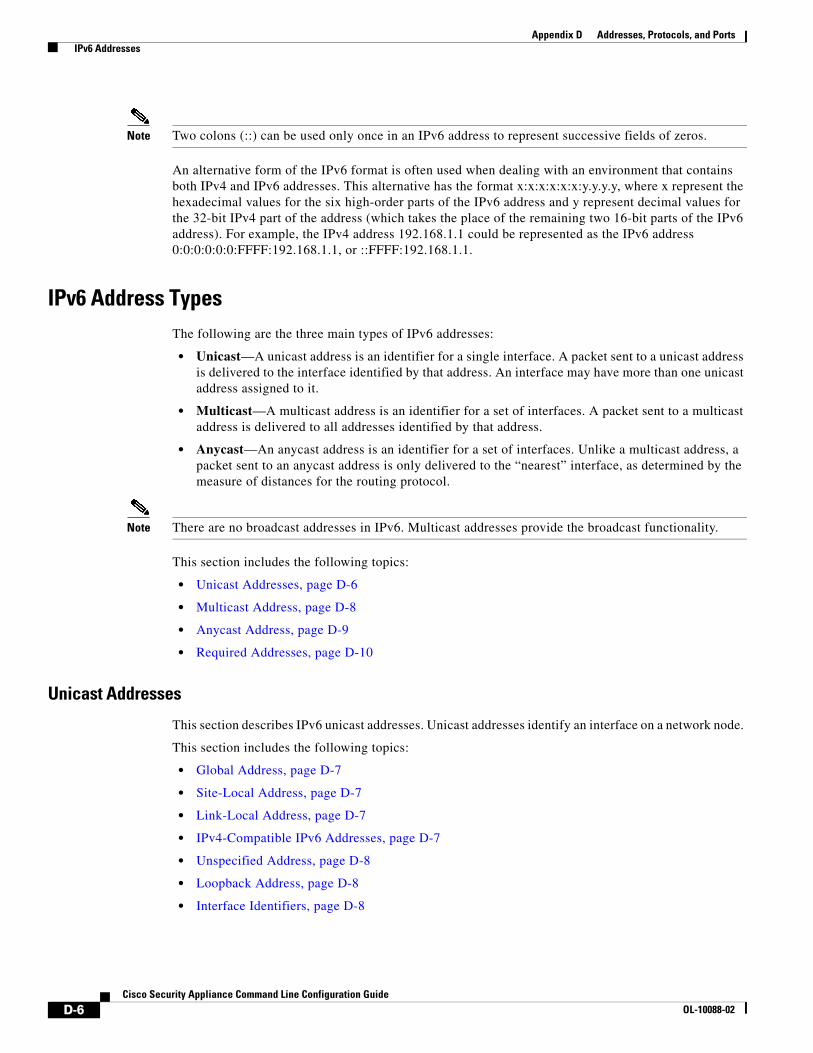
IPv6 Address TypesThe following are the three main types of IPv6 addresses:
• Unicast—A unicast address is an identifier for a single interface. A packet sent to a unicast address is delivered to the interface identified by that address. An interface may have more than one unicast address assigned to it.
• Multicast—A multicast address is an identifier for a set of interfaces. A packet sent to a multicast address is delivered to all addresses identified by that address.
• Anycast—An anycast address is an identifier for a set of interfaces. Unlike a multicast address, a packet sent to an anycast address is only delivered to the “nearest” interface, as determined by the measure of distances for the routing protocol.
Note There are no broadcast addresses in IPv6. Multicast addresses provide the broadcast functionality.
This section includes the following topics:
• Unicast Addresses, page D-6
• Multicast Address, page D-8
• Anycast Address, page D-9
• Required Addresses, page D-10
Unicast Addresses
This section describes IPv6 unicast addresses. Unicast addresses identify an interface on a network node.
This section includes the following topics:
• Global Address, page D-7
• Site-Local Address, page D-7
• Link-Local Address, page D-7
• IPv4-Compatible IPv6 Addresses, page D-7
• Unspecified Address, page D-8
• Loopback Address, page D-8
• Interface Identifiers, page D-8
D-6Cisco Security Appliance Command Line Configuration Guide
OL-10088-02

Appendix D Addresses, Protocols, and Ports IPv6 Addresses
Global Address
The general format of an IPv6 global unicast address is a global routing prefix followed by a subnet ID followed by an interface ID. The global routing prefix can be any prefix not reserved by another IPv6 address type (see IPv6 Address Prefixes, page D-10, for information about the IPv6 address type prefixes).
All global unicast addresses, other than those that start with binary 000, have a 64-bit interface ID in the Modified EUI-64 format. See Interface Identifiers, page D-8, for more information about the Modified EUI-64 format for interface identifiers.
Global unicast address that start with the binary 000 do not have any constraints on the size or structure of the interface ID portion of the address. One example of this type of address is an IPv6 address with an embedded IPv4 address (see IPv4-Compatible IPv6 Addresses, page D-7).
Site-Local Address
Site-local addresses are used for addressing within a site. They can be use to address an entire site without using a globally unique prefix. Site-local addresses have the prefix FEC0::/10, followed by a 54-bit subnet ID, and end with a 64-bit interface ID in the modified EUI-64 format.
Site-local Routers do not forward any packets that have a site-local address for a source or destination outside of the site. Therefore, site-local addresses can be considered private addresses.
Link-Local Address
All interfaces are required to have at least one link-local address. You can configure multiple IPv6 addresses per interfaces, but only one link-local address.
A link-local address is an IPv6 unicast address that can be automatically configured on any interface using the link-local prefix FE80::/10 and the interface identifier in modified EUI-64 format. Link-local addresses are used in the neighbor discovery protocol and the stateless autoconfiguration process. Nodes with a link-local address can communicate; they do not need a site-local or globally unique address to communicate.
Routers do not forward any packets that have a link-local address for a source or destination. Therefore, link-local addresses can be considered private addresses.
IPv4-Compatible IPv6 Addresses
There are two types of IPv6 addresses that can contain IPv4 addresses.
The first type is the “IPv4-compatibly IPv6 address.” The IPv6 transition mechanisms include a technique for hosts and routers to dynamically tunnel IPv6 packets over IPv4 routing infrastructure. IPv6 nodes that use this technique are assigned special IPv6 unicast addresses that carry a global IPv4 address in the low-order 32 bits. This type of address is termed an “IPv4-compatible IPv6 address” and has the format ::y.y.y.y, where y.y.y.y is an IPv4 unicast address.
Note The IPv4 address used in the “IPv4-compatible IPv6 address” must be a globally-unique IPv4 unicast address.
The second type of IPv6 address which holds an embedded IPv4 address is called the “IPv4-mapped IPv6 address.” This address type is used to represent the addresses of IPv4 nodes as IPv6 addresses. This type of address has the format ::FFFF:y.y.y.y, where y.y.y.y is an IPv4 unicast address.
D-7Cisco Security Appliance Command Line Configuration Guide
OL-10088-02

Appendix D Addresses, Protocols, and Ports IPv6 Addresses
Unspecified Address
The unspecified address, 0:0:0:0:0:0:0:0, indicates the absence of an IPv6 address. For example, a newly initialized node on an IPv6 network may use the unspecified address as the source address in its packets until it receives its IPv6 address.
Note The IPv6 unspecified address cannot be assigned to an interface. The unspecified IPv6 addresses must not be used as destination addresses in IPv6 packets or the IPv6 routing header.
Loopback Address
The loopback address, 0:0:0:0:0:0:0:1, may be used by a node to send an IPv6 packet to itself. The loopback address in IPv6 functions the same as the loopback address in IPv4 (127.0.0.1).
Note The IPv6 loopback address cannot be assigned to a physical interface. A packet that has the IPv6 loopback address as its source or destination address must remain within the node that created the packet. IPv6 routers do not forward packets that have the IPv6 loopback address as their source or destination address.
Interface Identifiers
Interface identifiers in IPv6 unicast addresses are used to identify the interfaces on a link. They need to be unique within a subnet prefix. In many cases, the interface identifier is derived from the interface link-layer address. The same interface identifier may be used on multiple interfaces of a single node, as long as those interfaces are attached to different subnets.
For all unicast addresses, except those that start with the binary 000, the interface identifier is required to be 64 bits long and to be constructed in the Modified EUI-64 format. The Modified EUI-64 format is created from the 48-bit MAC address by inverting the universal/local bit in the address and by inserting the hexadecimal number FFFE between the upper three bytes and lower three bytes of the of the MAC address.
For example, and interface with the MAC address of 00E0.b601.3B7A would have a 64-bit interface ID of 02E0:B6FF:FE01:3B7A.
Multicast Address
An IPv6 multicast address is an identifier for a group of interfaces, typically on different nodes. A packet sent to a multicast address is delivered to all interfaces identified by the multicast address. An interface may belong to any number of multicast groups.
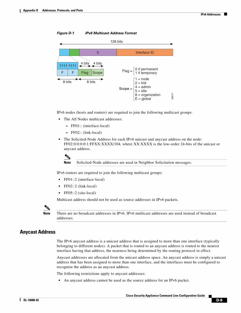
An IPv6 multicast address has a prefix of FF00::/8 (1111 1111). The octet following the prefix defines the type and scope of the multicast address. A permanently assigned (“well known”) multicast address has a flag parameter equal to 0; a temporary (“transient”) multicast address has a flag parameter equal to 1. A multicast address that has the scope of a node, link, site, or organization, or a global scope has a scope parameter of 1, 2, 5, 8, or E, respectively. For example, a multicast address with the prefix FF02::/16 is a permanent multicast address with a link scope. Figure D-1 shows the format of the IPv6 multicast address.
D-8Cisco Security Appliance Command Line Configuration Guide
OL-10088-02
Appendix D Addresses, Protocols, and Ports IPv6 Addresses
Figure D-1 IPv6 Multicast Address Format
IPv6 nodes (hosts and routers) are required to join the following multicast groups:
• The All Nodes multicast addresses:
– FF01:: (interface-local)
– FF02:: (link-local)
• The Solicited-Node Address for each IPv6 unicast and anycast address on the node: FF02:0:0:0:0:1:FFXX:XXXX/104, where XX:XXXX is the low-order 24-bits of the unicast or anycast address.
Note Solicited-Node addresses are used in Neighbor Solicitation messages.
IPv6 routers are required to join the following multicast groups:
• FF01::2 (interface-local)
• FF02::2 (link-local)
• FF05::2 (site-local)
Multicast address should not be used as source addresses in IPv6 packets.
Note There are no broadcast addresses in IPv6. IPv6 multicast addresses are used instead of broadcast addresses.
Anycast Address
The IPv6 anycast address is a unicast address that is assigned to more than one interface (typically belonging to different nodes). A packet that is routed to an anycast address is routed to the nearest interface having that address, the nearness being determined by the routing protocol in effect.
Anycast addresses are allocated from the unicast address space. An anycast address is simply a unicast address that has been assigned to more than one interface, and the interfaces must be configured to recognize the address as an anycast address.
The following restrictions apply to anycast addresses:
• An anycast address cannot be used as the source address for an IPv6 packet.
9261
7
128 bits
4 bits4 bits
0 if permanent1 if temporary
Interface ID0
1111 1111
8 bits 8 bits
F F Flag Scope Flag =
Scope =
1 = node2 = link4 = admin5 = site8 = organizationE = global
D-9Cisco Security Appliance Command Line Configuration Guide
OL-10088-02

Appendix D Addresses, Protocols, and Ports IPv6 Addresses
• An anycast address cannot be assigned to an IPv6 host; it can only be assigned to an IPv6 router.
Note Anycast addresses are not supported on the security appliance.
Required Addresses
IPv6 hosts must, at a minimum, be configured with the following addresses (either automatically or manually):
• A link-local address for each interface.
• The loopback address.
• The All-Nodes multicast addresses
• A Solicited-Node multicast address for each unicast or anycast address.
IPv6 routers must, at a minimum, be configured with the following addresses (either automatically or manually):
• The required host addresses.
• The Subnet-Router anycast addresses for all interfaces for which it is configured to act as a router.
• The All-Routers multicast addresses.
IPv6 Address PrefixesAn IPv6 address prefix, in the format ipv6-prefix/prefix-length, can be used to represent bit-wise contiguous blocks of the entire address space. The IPv6-prefix must be in the form documented in RFC 2373 where the address is specified in hexadecimal using 16-bit values between colons. The prefix length is a decimal value that indicates how many of the high-order contiguous bits of the address comprise the prefix (the network portion of the address). For example, 2001:0DB8:8086:6502::/32 is a valid IPv6 prefix.
The IPv6 prefix identifies the type of IPv6 address. Table D-3 shows the prefixes for each IPv6 address type.
Table D-3 IPv6 Address Type Prefixes
Address Type Binary Prefix IPv6 Notation
Unspecified 000...0 (128 bits) ::/128
Loopback 000...1 (128 bits) ::1/128
Multicast 11111111 FF00::/8
Link-Local (unicast) 1111111010 FE80::/10
Site-Local (unicast) 1111111111 FEC0::/10
Global (unicast) All other addresses.
Anycast Taken from the unicast address space.
D-10Cisco Security Appliance Command Line Configuration Guide
OL-10088-02

Appendix D Addresses, Protocols, and Ports Protocols and Applications
Protocols and ApplicationsTable D-4 lists the protocol literal values and port numbers; either can be entered in security appliance commands.
Protocol numbers can be viewed online at the IANA website:
http://www.iana.org/assignments/protocol-numbers
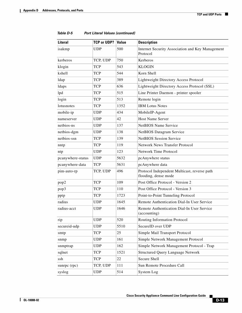
TCP and UDP PortsTable D-5 lists the literal values and port numbers; either can be entered in security appliance commands. See the following caveats:
• The security appliance uses port 1521 for SQL*Net. This is the default port used by Oracle for SQL*Net. This value, however, does not agree with IANA port assignments.
Table D-4 Protocol Literal Values
Literal Value Description
ah 51 Authentication Header for IPv6, RFC 1826.
eigrp 88 Enhanced Interior Gateway Routing Protocol.
esp 50 Encapsulated Security Payload for IPv6, RFC 1827.
gre 47 Generic Routing Encapsulation.
icmp 1 Internet Control Message Protocol, RFC 792.
icmp6 58 Internet Control Message Protocol for IPv6, RFC 2463.
igmp 2 Internet Group Management Protocol, RFC 1112.
igrp 9 Interior Gateway Routing Protocol.
ip 0 Internet Protocol.
ipinip 4 IP-in-IP encapsulation.
ipsec 50 IP Security. Entering the ipsec protocol literal is equivalent to entering the esp protocol literal.
nos 94 Network Operating System (Novell’s NetWare).
ospf 89 Open Shortest Path First routing protocol, RFC 1247.
pcp 108 Payload Compression Protocol.
pim 103 Protocol Independent Multicast.
pptp 47 Point-to-Point Tunneling Protocol. Entering the pptp protocol literal is equivalent to entering the gre protocol literal.
snp 109 Sitara Networks Protocol.
tcp 6 Transmission Control Protocol, RFC 793.
udp 17 User Datagram Protocol, RFC 768.
D-11Cisco Security Appliance Command Line Configuration Guide
OL-10088-02

Appendix D Addresses, Protocols, and Ports TCP and UDP Ports
• The security appliance listens for RADIUS on ports 1645 and 1646. If your RADIUS server uses the standard ports 1812 and 1813, you can configure the security appliance to listen to those ports using the authentication-port and accounting-port commands.
• To assign a port for DNS access, use the domain literal value, not dns. If you use dns, the security appliance assumes you meant to use the dnsix literal value.
Port numbers can be viewed online at the IANA website:
http://www.iana.org/assignments/port-numbers
Table D-5 Port Literal Values
Literal TCP or UDP? Value Description
aol TCP 5190 America Online
bgp TCP 179 Border Gateway Protocol, RFC 1163
biff UDP 512 Used by mail system to notify users that new mail is received
bootpc UDP 68 Bootstrap Protocol Client
bootps UDP 67 Bootstrap Protocol Server
chargen TCP 19 Character Generator
citrix-ica TCP 1494 Citrix Independent Computing Architecture (ICA) protocol
cmd TCP 514 Similar to exec except that cmd has automatic authentication
ctiqbe TCP 2748 Computer Telephony Interface Quick Buffer Encoding
daytime TCP 13 Day time, RFC 867
discard TCP, UDP 9 Discard
domain TCP, UDP 53 DNS
dnsix UDP 195 DNSIX Session Management Module Audit Redirector
echo TCP, UDP 7 Echo
exec TCP 512 Remote process execution
finger TCP 79 Finger
ftp TCP 21 File Transfer Protocol (control port)
ftp-data TCP 20 File Transfer Protocol (data port)
gopher TCP 70 Gopher
https TCP 443 HTTP over SSL
h323 TCP 1720 H.323 call signalling
hostname TCP 101 NIC Host Name Server
ident TCP 113 Ident authentication service
imap4 TCP 143 Internet Message Access Protocol, version 4
irc TCP 194 Internet Relay Chat protocol
D-12Cisco Security Appliance Command Line Configuration Guide
OL-10088-02
Appendix D Addresses, Protocols, and Ports TCP and UDP Ports
isakmp UDP 500 Internet Security Association and Key Management Protocol
kerberos TCP, UDP 750 Kerberos
klogin TCP 543 KLOGIN
kshell TCP 544 Korn Shell
ldap TCP 389 Lightweight Directory Access Protocol
ldaps TCP 636 Lightweight Directory Access Protocol (SSL)
lpd TCP 515 Line Printer Daemon - printer spooler
login TCP 513 Remote login
lotusnotes TCP 1352 IBM Lotus Notes
mobile-ip UDP 434 MobileIP-Agent
nameserver UDP 42 Host Name Server
netbios-ns UDP 137 NetBIOS Name Service
netbios-dgm UDP 138 NetBIOS Datagram Service
netbios-ssn TCP 139 NetBIOS Session Service
nntp TCP 119 Network News Transfer Protocol
ntp UDP 123 Network Time Protocol
pcanywhere-status UDP 5632 pcAnywhere status
pcanywhere-data TCP 5631 pcAnywhere data
pim-auto-rp TCP, UDP 496 Protocol Independent Multicast, reverse path flooding, dense mode
pop2 TCP 109 Post Office Protocol - Version 2
pop3 TCP 110 Post Office Protocol - Version 3
pptp TCP 1723 Point-to-Point Tunneling Protocol
radius UDP 1645 Remote Authentication Dial-In User Service
radius-acct UDP 1646 Remote Authentication Dial-In User Service (accounting)
rip UDP 520 Routing Information Protocol
secureid-udp UDP 5510 SecureID over UDP
smtp TCP 25 Simple Mail Transport Protocol
snmp UDP 161 Simple Network Management Protocol
snmptrap UDP 162 Simple Network Management Protocol - Trap
sqlnet TCP 1521 Structured Query Language Network
ssh TCP 22 Secure Shell
sunrpc (rpc) TCP, UDP 111 Sun Remote Procedure Call
syslog UDP 514 System Log
Table D-5 Port Literal Values (continued)
Literal TCP or UDP? Value Description
D-13Cisco Security Appliance Command Line Configuration Guide
OL-10088-02

Appendix D Addresses, Protocols, and Ports Local Ports and Protocols
Local Ports and ProtocolsTable D-6 lists the protocols, TCP ports, and UDP ports that the security appliance may open to process traffic destined to the security appliance. Unless you enable the features and services listed in Table D-6, the security appliance does not open any local protocols or any TCP or UDP ports. You must configure a feature or service for the security appliance to open the default listening protocol or port. In many cases you can configure ports other than the default port when you enable a feature or service.
tacacs TCP, UDP 49 Terminal Access Controller Access Control System Plus
talk TCP, UDP 517 Talk
telnet TCP 23 RFC 854 Telnet
tftp UDP 69 Trivial File Transfer Protocol
time UDP 37 Time
uucp TCP 540 UNIX-to-UNIX Copy Program
who UDP 513 Who
whois TCP 43 Who Is
www TCP 80 World Wide Web
xdmcp UDP 177 X Display Manager Control Protocol
Table D-5 Port Literal Values (continued)
Literal TCP or UDP? Value Description
Table D-6 Protocols and Ports Opened by Features and Services
Feature or Service Protocol Port Number Comments
DHCP UDP 67,68 —
Failover Control 108 N/A —
HTTP TCP 80 —
HTTPS TCP 443 —
ICMP 1 N/A —
IGMP 2 N/A Protocol only open on destination IP address 224.0.0.1
ISAKMP/IKE UDP 500 Configurable.
IPSec (ESP) 50 N/A —
IPSec over UDP (NAT-T)
UDP 4500 —
IPSec over UDP (Cisco VPN 3000 Series compatible)
UDP 10000 Configurable.
IPSec over TCP (CTCP)
TCP — No default port is used. You must specify the port number when configuring IPSec over TCP.
D-14Cisco Security Appliance Command Line Configuration Guide
OL-10088-02

Appendix D Addresses, Protocols, and Ports ICMP Types
ICMP TypesTable D-7 lists the ICMP type numbers and names that you can enter in security appliance commands:
NTP UDP 123 —
OSPF 89 N/A Protocol only open on destination IP address 224.0.0.5 and 224.0.0.6
PIM 103 N/A Protocol only open on destination IP address 224.0.0.13
RIP UDP 520 —
RIPv2 UDP 520 Port only open on destination IP address 224.0.0.9
SNMP UDP 161 Configurable.
SSH TCP 22 —
Stateful Update 105 N/A —
Telnet TCP 23 —
VPN Load Balancing UDP 9023 Configurable.
VPN Individual User Authentication Proxy
UDP 1645, 1646 Port accessible only over VPN tunnel.
Table D-6 Protocols and Ports Opened by Features and Services (continued)
Feature or Service Protocol Port Number Comments
Table D-7 ICMP Types
ICMP Number ICMP Name
0 echo-reply
3 unreachable
4 source-quench
5 redirect
6 alternate-address
8 echo
9 router-advertisement
10 router-solicitation
11 time-exceeded
12 parameter-problem
13 timestamp-request
14 timestamp-reply
15 information-request
16 information-reply
17 mask-request
D-15Cisco Security Appliance Command Line Configuration Guide
OL-10088-02

Appendix D Addresses, Protocols, and Ports ICMP Types
18 mask-reply
31 conversion-error
32 mobile-redirect
Table D-7 ICMP Types (continued)
ICMP Number ICMP Name
D-16Cisco Security Appliance Command Line Configuration Guide
OL-10088-02


![Troubleshooting Catalyst 6500/6000 Series … Backplane Traffic Registers 100 Percent Out−Discards Increment on Supervisor Engine 32 Ports Multicast MAC Addresses [3333.0000.0000.000x]](https://static.fdocuments.in/doc/165x107/5b07788a7f8b9a5c308e6801/troubleshooting-catalyst-65006000-series-backplane-traffic-registers-100-percent.jpg)