Address: Midas Componen Ltd, Electra H YYarmouth, Norfolk ... · 42 BLL Backlight drive (cathode...
33
Address: Email:sale Website:w Tel:+44(0 Fax:+44(0 Midas Componees@midascompo www.midascomp )1493 602602 0)1493 665111 nts Ltd, Electra H onents.co.uk ponents.co.uk ouse, 32 Southto own Road, Great Yarmouth, Norfo olk, England, NR3 1 ODU
Transcript of Address: Midas Componen Ltd, Electra H YYarmouth, Norfolk ... · 42 BLL Backlight drive (cathode...

Address: Email:saleWebsite:wTel:+44(0Fax:+44(0
Midas [email protected])1493 602602 0)1493 665111
nts Ltd, Electra Honents.co.uk ponents.co.uk
ouse, 32 Southtoown Road, Great YYarmouth, Norfoolk, England, NR31 ODU
lovickm
Rectangle
lovickm
Stamp
lovickm
Rectangle
lovickm
Stamp
lovickm
Rectangle
lovickm
Rectangle
lovickm
Rectangle
(2/33)SPECIFICATIONS No. 09TLM022 Issue: Apr. 1, 2010
Version History
Ver. Date Page Description1.0 Oct.6,2009 - - First issue
2

(3/33)SPECIFICATIONS No. 09TLM022 Issue: Apr. 1, 2010
Contents
1. Application ・・・・・・・・・ 42. Outline Specifications
2.1 Features of the Product ・・・・・・・・・ 52.2 Display Method ・・・・・・・・・ 5
3. Dimensions and Shape3.1 Dimensions ・・・・・・・・・ 73.2 Outward Form ・・・・・・・・・ 83.3 Serial Label (S-LABEL) ・・・・・・・・・ 9
4. Pin Assignment ・・・・・・・・・ 105. Absolute Maximum Rating ・・・・・・・・・ 116. Recommended Operating Conditions ・・・・・・・・・ 117. Characteristics
7.1 DC Characteristics ・・・・・・・・・ 127.2 AC Characteristics ・・・・・・・・・ 127.3 Input Timing Characteristics ・・・・・・・・・ 147.4 Driving Timing Chart ・・・・・・・・・ 157.5 Example of Driving Timing Chart ・・・・・・・・・ 16
8. Description of Sequence8.1 Power ON/OFF Sequence ・・・・・・・・・ 178.2 Stanby ON/OFF Sequence ・・・・・・・・・ 18
9. LED Circuit ・・・・・・・・・ 1910. Characteristics
10.1 Optical Characteristics ・・・・・・・・・ 2010.2 Temperature Characteristics ・・・・・・・・・ 21
11. Criteria of Judgment11.1 Defective Display and Screen Quality ・・・・・・・・・ 2211.2 Screen and Other Appearance ・・・・・・・・・ 23
12. Reliability Test ・・・・・・・・・ 2413. Packing Specifications ・・・・・・・・・ 2614. Handling Instruction
14.1 Cautions for Handling LCD panels ・・・・・・・・・ 2714.2 Precautions for Handling ・・・・・・・・・ 2814.3 Precautions for Operation ・・・・・・・・・ 2814.4 Storage Condition for Shipping Cartons ・・・・・・・・・ 2914.5 Precautions for Peeling off ・・・・・・・・・ 29
the Protective film APPENDIX ・・・・・・・・・ 30
3

(4/33)SPECIFICATIONS No. 09TLM022 Issue: Apr. 1, 2010
1. Application
This Specification is applicable to 10.9cm (4.3 inch) Blanview TFT-LCD monitor for non-military use.
Midas Components makes no warranty or assume no liability that use of this Product and/or any information including drawings in this Specification by Purchaser is not infringing any patent or other intellectual property rights owned by third parties, and Midas Components shall not grant to Purchaser any right to use any patent or other intellectual property rights owned by third parties. Since this Specification contains Midas Components confidential information and copy right, Purchaser shall use them with high degree of care to prevent any unauthorized use, disclosure, duplication, publication or dissemination of Midas Components confidential information and copy right.
If Purchaser intends to use this Products for an application which requires higher level of reliability and/or safety in functionality and/or accuracy such as transport equipment (aircraft, train automobile etc.), disaster-prevention/security equipment or various safety equipment, Purchaser shall consult Midas Components on such use in advance.
This Product shall not be used for application which requires extremely higher level of reliability and/or safety such as aerospace equipment, telecommunication equipment for trunk lines, control equipment for nuclear facilities or life-support medical equipment.
Midas Components assumes no liability for any damage resulting from misuse, abuse, and/or miss-operation of the Product deviating from the operating conditions and precautions
described in the Specification.
If any issue arises as to information provided in this Specification or any other information, Midas Components and Purchaser shall discuss them in good faith and seek solution.
Midas Components assumes no liability for defects such as electrostatic discharge failure occurred during peeling off the protective film or Purchaser's assembly process.
This Product is compatible for RoHS directive. Object substance Maximum content [ppm]
Cadmium and its compound 100Hexavalent Chromium Compound 1000Lead & Lead compound 1000Mercury & Mercury compound 1000Polybrominated biphenyl series(PBB series) 1000Polybrominated biphenyl ether series(PBDE series) 1000
4

(5/33)SPECIFICATIONS No. 09TLM022 Issue: Apr. 1, 2010
2. Outline Specifications
2.1 Features of the Product
- 4.3 inch diagonal display, 1,440 [H] x 272 [V] dots.- 8-bit 16,777,216 color display capability.- Single power supply operation of 3.3V.- Built in Timing generator (TG), Counter-electrode driving circuitry and power supply circuit.- High bright white LED back-light.- Blanview TFT-LCD, improved outdoor readability.
Readability Power Efficiency Readability Power Efficiency(Battery Life) (Battery Life)
2.2 Display Method
Items Specifications RemarksDisplay type TN type 16,777,216 colors.
Blanview, Normally white.Driving method a-Si TFT Active matrix.
Line-scanning, Non-interlace.Dot arrangement RGB stripe arrangement. Refer to "Dot arrangement".Signal input method 8-bit RGB, parallel input.Backlight type High bright white LED.
Active area
X1 X2 ・ ・ ・ ・ ・ X479 X4801 2 3 4 1437 1438 1439 1440
・ ・ ・ ・
・ ・ ・ ・ Active area・ ・ ・ ・
Dot arrangement (FPC cable placed downside)
Poor
Good
Good
Transmissive
Transflective
Blanview
Good
Fair
Good
Good
Poor
Good
Fair
Good
Good
Y1 R G B R ・ ・ ・ ・ ・ B R G B
Y2 R G B R ・ ・ ・ ・ B・ B R G
・ ・
R
R・ ・
G
G
B
B
Y271
Y272
R
R
R
R
B
B
・ ・ ・ ・ ・
・
G
G
B
B
Indoor Outdoor
5

(6/33)SPECIFICATIONS No. 09TLM022 Issue: Apr. 1, 2010
<Features of Blanview>
- Backlight power consumption required to assure visibility. (equivalent to 3.5”QVGA )
- Contrast characteristics under 100,000Lx. (same condition as direct sunlight.)
With better contrast (higher contrast ratio), Blanview TFT-LCD has the best outdoor readabilityin three different types of TFT-LCD. Below chart shows contrast value against panel surface brightness. (Horizontal: Panel surface brightness/Vertical: Contrast value) LCD panel has enough outdoor readability above our Standard line. (ORTUS TECHNOLOGY criteria)
CRパネル輝度 Blanview 半透過 透過型 OKライン
0 1.125 0.875 0.375 1.00
100 1.00
200 1.00
300 2 1.00
400 1.125 1.00
500 1.00
600 1.00
700 1.00
800 1.00
900 1.00
1000 1.25 1.00
0 200 400 600 800 1000
Panel surface brightness (cd/m2)
Con
trast
Blanview
Transmissive
Transflective
*Comparison with our conventional products
Standard
0
400
800
Surrounding illumination (Lx)
Blanview
Transmissive
Transflective
100
200
600
*Comparison with our conventional products
Transmissivity is low,requiring a power-hungry
backlight Power-hungry backlightthat competes effectively
with outdoor light isrequired.
Improved contrast,whiteness and
outdoor visibility.
100,000Fine weather
10,000Cloudy weather
1,000Office
100Warehouse
10Moonlight
Bac
klig
ht p
ower
con
sum
ptio
n (m
W)
6
lovickm
Rectangle
(7/33)SPECIFICATIONS No. 09TLM022 Issue: Apr. 1, 2010
3. Dimensions and Shape
3.1 Dimensions
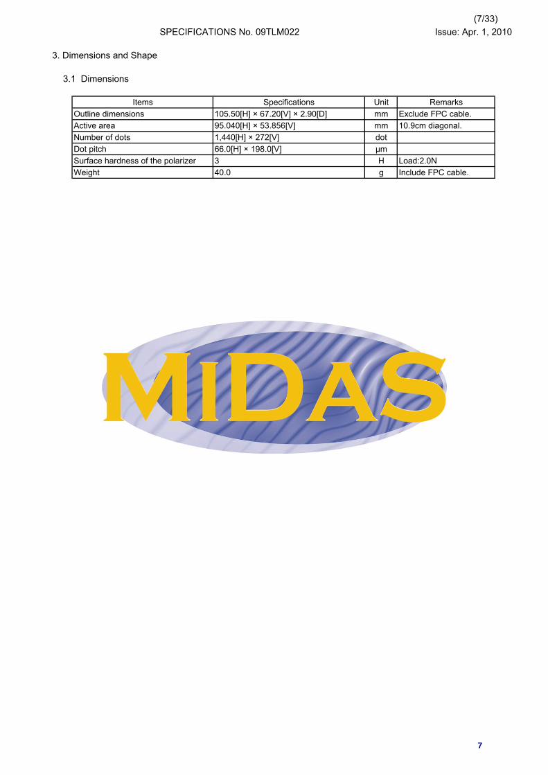
Items Specifications Unit RemarksOutline dimensions 105.50[H] × 67.20[V] × 2.90[D] mm Exclude FPC cable.Active area 95.040[H] × 53.856[V] mm 10.9cm diagonal.Number of dots 1,440[H] × 272[V] dotDot pitch 66.0[H] × 198.0[V] μmSurface hardness of the polarizer 3 H Load:2.0NWeight 40.0 g Include FPC cable.
7

tojom
テキストボックス
3.2 Outward Form
tojom
テキストボックス
(8/33) 09TLM022 Issue:Apr.1,2010
lovickm
Rectangle
lovickm
Rectangle
lovickm
Rectangle
(9/33)SPECIFICATIONS No. 09TLM022 Issue: Apr. 1, 2010
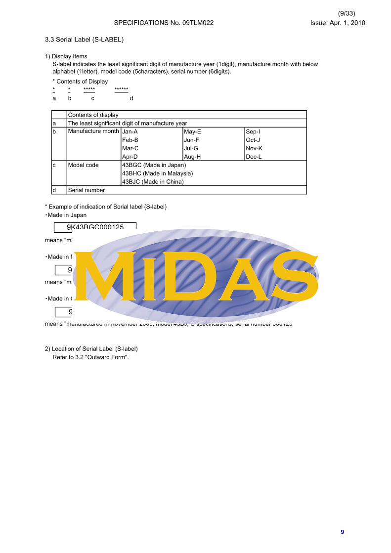
3.3 Serial Label (S-LABEL)
1) Display Items
* Contents of Display* * ***** ******a b c d
Contents of displaya The least significant digit of manufacture yearb Jan-A May-E Sep-I
Feb-B Jun-F Oct-JMar-C Jul-G Nov-KApr-D Aug-H Dec-L
c Model code 43BGC (Made in Japan)43BHC (Made in Malaysia)43BJC (Made in China)
d Serial number
* Example of indication of Serial label (S-label)・Made in Japan
means "manufactured in November 2009, model 43BG, C specifications, serial number 000125"
・Made in Malaysia
means "manufactured in November 2009, model 43BH, C specifications, serial number 000125"
・Made in China
means "manufactured in November 2009, model 43BJ, C specifications, serial number 000125"
2) Location of Serial Label (S-label)Refer to 3.2 "Outward Form".
S-label indicates the least significant digit of manufacture year (1digit), manufacture month with belowalphabet (1letter), model code (5characters), serial number (6digits).
Manufacture month
9K43BGC000125
9K43BJC000125
9K43BHC000125
9
(10/33)SPECIFICATIONS No. 09TLM022 Issue: Apr. 1, 2010
4. Pin Assignment
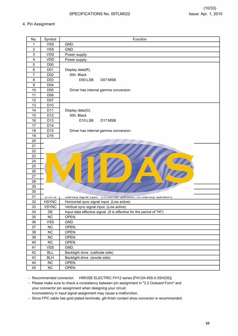
No. Symbol Function1 VSS GND.2 VSS GND.3 VDD Power supply.4 VDD Power supply.5 D006 D01 Display data(R).7 D02 00h: Black8 D03 D00:LSB D07:MSB9 D04
10 D05 Driver has internal gamma conversion.11 D0612 D0713 D1014 D11 Display data(G).15 D12 00h: Black16 D13 D10:LSB D17:MSB17 D1418 D15 Driver has internal gamma conversion.19 D1620 D1721 D2022 D21 Display data(B).23 D22 00h: Black24 D23 D20:LSB D27:MSB25 D2426 D25 Driver has internal gamma conversion.27 D2628 D2729 VSS GND.30 CLK Clock signal.Latching data at the falling edge.31 STBYB Standby signal input. (Hi:Normal operation, Lo:Standby operation)32 HSYNC Horizontal sync signal input. (Low active)33 VSYNC Vertical sync signal input. (Low active)34 DE Input data effective signal. (It is effective for the period of "Hi")35 NC OPEN.36 VSS GND.37 NC OPEN.38 NC OPEN.39 NC OPEN.40 NC OPEN.41 VSS GND.42 BLL Backlight drive (cathode side)43 BLH Backlight drive (anode side)44 NC OPEN.45 NC OPEN.
- Recommended connector: HIROSE ELECTRIC FH12 series [FH12A-45S-0.5SH(55)]- Please make sure to check a consistency between pin assignment in "3.2 Outward Form" and
your connector pin assignment when designing your circuit.Inconsistency in input signal assignment may cause a malfunction.
- Since FPC cable has gold plated terminals, gilt finish contact shoe connector is recommended.
10
(11/33)SPECIFICATIONS No. 09TLM022 Issue: Apr. 1, 2010
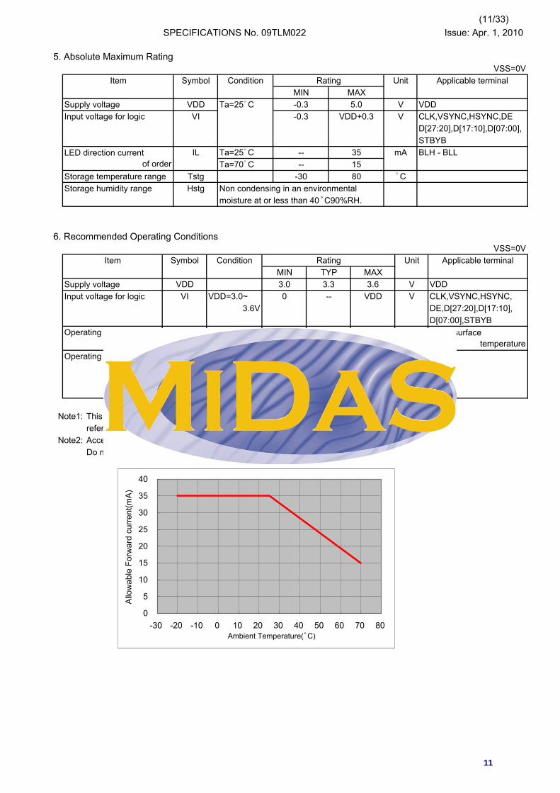
5. Absolute Maximum RatingVSS=0V
Item Symbol Condition Rating Unit Applicable terminalMIN MAX
Supply voltage VDD Ta=25゜C -0.3 5.0 V VDDInput voltage for logic VI -0.3 VDD+0.3 V CLK,VSYNC,HSYNC,DE
D[27:20],D[17:10],D[07:00],STBYB
LED direction current IL Ta=25゜C -- 35 mA BLH - BLLof order Ta=70゜C -- 15
Storage temperature range Tstg -30 80 ゜CStorage humidity range Hstg Non condensing in an environmental
moisture at or less than 40゜C90%RH.
6. Recommended Operating ConditionsVSS=0V
Item Symbol Condition Rating Unit Applicable terminalMIN TYP MAX
Supply voltage VDD 3.0 3.3 3.6 V VDDInput voltage for logic VI VDD=3.0~ 0 -- VDD V CLK,VSYNC,HSYNC,
3.6V DE,D[27:20],D[17:10],D[07:00],STBYB
Operating temperatur Top Note 1,2 -20 25 70 ゜C Panel surfacerange temperature
Operating humidity Ta≦30゜C 20 -- 80 %range Hop Ta>30゜C Non condensing in
an environmental moisture at orless than 30゜C80%RH.
Note1: This monitor is operatable in this temperature range. With regard to optical characteristics, refer to Item "10. CHARACTERISTICS".
Note2: Acceptable Forward Current to LED is up to 15mA, when Ta=+70゜C.Do not exceed Allowable Forward Current shown on the chart below.
## #### #### ##
0
5
10
15
20
25
30
35
40
-30 -20 -10 0 10 20 30 40 50 60 70 80Ambient Temperature(゜C)
Allo
wab
le F
orw
ard
curre
nt(m
A)
11

(12/33)SPECIFICATIONS No. 09TLM022 Issue: Apr. 1, 2010
7. Characteristics
7.1 DC Characteristics
7.1.1 Display Module(Unless otherwise noted, Ta=25゜C,VDD=3.3V,VSS=0V)
Item Symbol Condition Rating Unit Applicable terminalMIN TYP MAX
Input voltage VIH VDD=3.0~3.6V 0.7×VDD -- VDD V CLK,VSYNC,HSYNC, for logic DE,D[27:20],D[17:10],
VIL 0 -- 0.3×VDD V D[07:00],STBYB
Pull down Rpd -- 200 -- kΩ DE,D[27:20],D[17:10],resister value D[07:00]
Pull up Rpu -- 200 -- kΩ VSYNC,HSYNC,resister value STBYB
Current IDD fCLK=9MHz -- 17 34 mA VDDconsumption Color bar display
Standby Current IDDs Other input with constant -- 100 200 μAvoltage
7.1.2 Backlight
Item Symbol Condition Rating Unit Applicable terminalMIN TYP MAX
Forward current IL25 Ta=25゜C -- 10.0 35.0 mA BLH - BLLIL70 Ta=70゜C -- -- 15.0 mA
Forward voltage VL Ta=25゜C,IL=10.0mA -- 27.0 29.7 VEstimated Life LL Ta=25゜C,IL=10.0mA -- (20,000) -- hr
of LED Note
Note: - The lifetime of the LED is defined as a period till the brightness of the LED decreases to the half of its initial value.
- This figure is given as a reference purpose only, and not as a guarantee.- This figure is estimated for an LED operating alone.
As the performance of an LED may differ when assembled as a monitor together with a TFT panel due to different environmental temperature.
- Estimated lifetime could vary on a different temperature and usually higher temperature could reduce the life significantly.
7.2 AC Characteristics(Unless otherwise noted, Ta=25゜C,VDD=3.3V,VSS=0V)
Item Symbol Condition Rating Unit Applicable terminalMIN TYP MAX
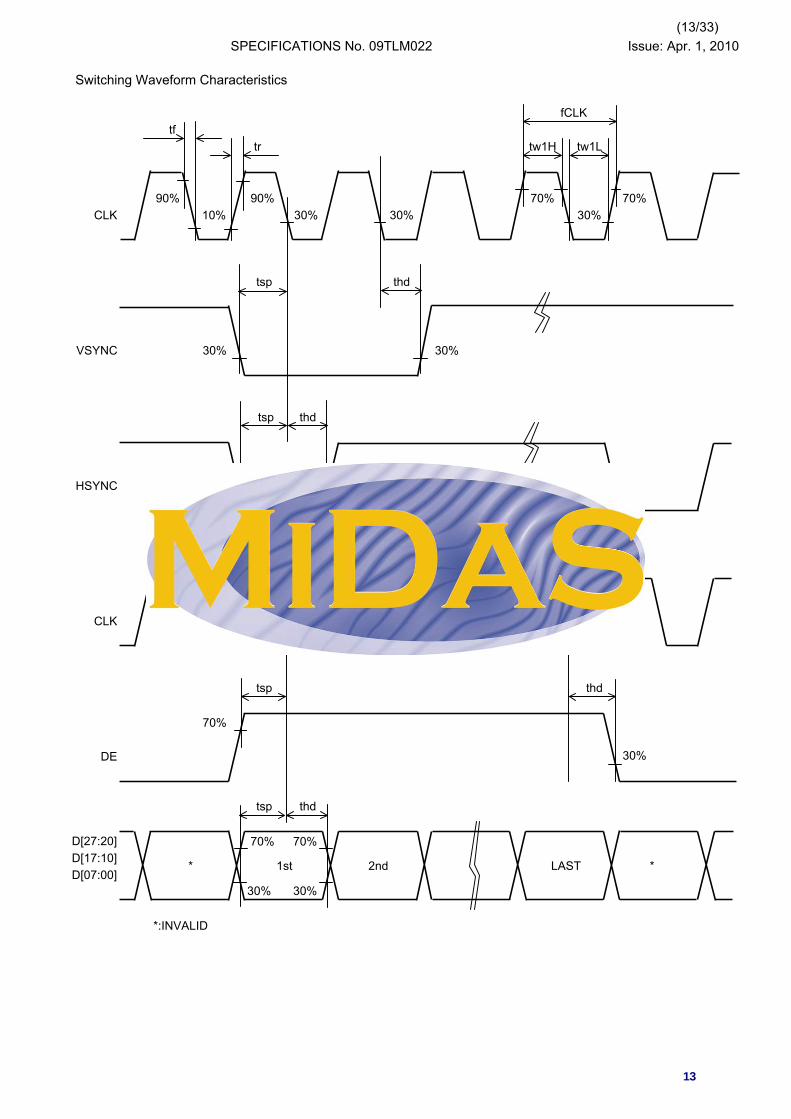
CLK frequency fCLK 5.0 9.0 12.0 MHz CLKCLK rising time tr 10%→90% -- -- 9 nsCLK falling time tf 90%→10% -- -- 9 nsCLK Low period tw1L 0.3×VDD or less. 0.4/fCLK -- 0.6/fCLK nsCLK High period tw1H 0.7×VDD or more. 0.4/fCLK -- 0.6/fCLK nsSetup time tsp 12.0 -- -- ns CLK,VSYNC,HSYNC,Hold time thd 12.0 -- -- ns DE,D[27:20],D[17:10],
D[07:00]
12
(13/33)SPECIFICATIONS No. 09TLM022 Issue: Apr. 1, 2010
Switching Waveform Characteristics
fCLKtf
tr tw1H tw1L
90% 90% 70% 70%CLK 10% 30% 30% 30%
tsp thd
VSYNC 30% 30%
tsp thd
HSYNC 30% 30%
CLK 30% 30%
tsp thd
70%
DE 30%
tsp thd
D[27:20] 70% 70% D[17:10]D[07:00]
30% 30%
*:INVALID
** 1st 2nd LAST
13
(14/33)SPECIFICATIONS No. 09TLM022 Issue: Apr. 1, 2010
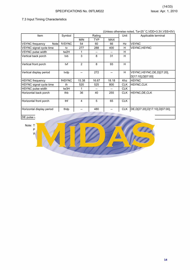
7.3 Input Timing Characteristics
(Unless otherwise noted, Ta=25゜C,VDD=3.3V,VSS=0V)Item Symbol Rating Unit Applicable terminal
MIN TYP MAXVSYNC frequency Note fVSYNC 54 60 66 Hz VSYNCVSYNC signal cycle time tv 277 288 400 H VSYNC,HSYNCVSYNC pulse width tw2H 1 -- -- HVertical back porch tvb 3 8 31 H
Vertical front porch tvf 2 8 93 H
Vertical display period tvdp -- 272 -- H VSYNC,HSYNC,DE,D[27:20],D[17:10],D[07:00]
HSYNC frequency fHSYNC 15.38 16.67 18.18 Khz HSYNCHSYNC signal cycle time th 520 525 800 CLK HSYNC,CLKHSYNC pulse width tw3H 1 -- -- CLKHorizontal back porch thb 36 40 255 CLK HSYNC,DE,CLK
Horizontal front porch thf 4 5 65 CLK
Horizontal display period thdp -- 480 -- CLK DE,D[27:20],D[17:10],D[07:00],CLK
DE pulse width tw4H -- 480 -- CLK DE,CLK
Note: The characteristic of this item is recommended standard. Please use it after it confirms it enough like the display fineness etc. When it comes off from this characteristic and it is used.
14

(15/33)SPECIFICATIONS No. 09TLM022 Issue: Apr. 1, 2010
7.4 Driving Timing Chart
-Vertical Timing
tv
tw2H
VSYNC1H
HSYNC
tvb tvdp tvf
DE
D[27:20]D[17:10] Y1 Y2 Y3 Y4 Y270 Y271 Y272
D[07:00]
-Horizontal Timing
th
tw3H
HSYNC
CLK
thb tw4H thf
DE
thb thdp
D[27:20]D[17:10]D[07:00]
* ** * * ** * * ** * * *X2
X4
X3
X48
0
X47
7X
478
X47
9
* * X1* * * *
15

(16/33)SPECIFICATIONS No. 09TLM022 Issue: Apr. 1, 2010
7.5 Example of Driving Timing Chart (fCLK=9.0MHz)
-Vertical Timing
288H
1H
VSYNC1H
HSYNC
8H 272H 8H
DE
D[27:20]D[17:10] Y1 Y2 Y3 Y4 Y270 Y271 Y272
D[07:00]
-Horizontal Timing
525CLK
2CLK
HSYNC
CLK
40CLK 480CLK 5CLK
DE
40CLK 480CLK
D[27:20]D[17:10]D[07:00]
** * * * X1
X2* * * * ** * * **
X47
7X
478
X47
9
X3
X4 * ** * * *
X48
0
*
16

(17/33)SPECIFICATIONS No. 09TLM022 Issue: Apr. 1, 2010
8. Description of Sequence
The outline of "Power ON/OFF Sequence" and "Standby ON/OFF Sequence" is shown below.
Power ON Power OFFSequence Standby ON/OFF Sequence Sequence
Stanby OFF Standby Standby Stanby OFF Standby StandbySequence Normal Operation ON period Sequence Normal Operation ON period
Sequence Sequence
VDD
STBYB
1 7 8 9 10 11 1 4 1 7 8 9 10 1 4VSYNC
Otherinput
signals
DISP White Normal Display White Display OFF White Normal Display White
Backlight OFF ON OFF ON OFF
8.1 Power ON/OFF Sequence
The sequence of the Power On/Off and the signal input must defend the following conditions.
Power ON Power OFF
VDDnote50ms
STBYB
1 2 3 4 5 6 7 8 9 10 11 1 2 3 4VSYNC
CLK
HSYNC
DE
DISP Display OFF Normal Display
Backlight OFF ON OFF
Note: For Power OFF,please turn off VDD since 50msec after the standby state shifts. When CLK and the VSYNC signal are stopped or the power supply is turned off to a regulated frame or less, the afterimage might remain.
State of standbyWhite DisplayWhite Display
17
(18/33)SPECIFICATIONS No. 09TLM022 Issue: Apr. 1, 2010
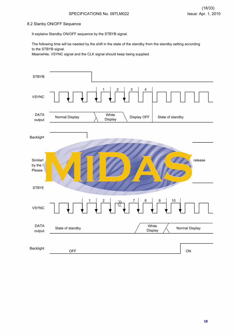
8.2 Stanby ON/OFF Sequence
It explains Standby ON/OFF sequence by the STBYB signal.
The following time will be needed by the shift in the state of the standby from the standby setting according to the STBYB signal. Meanwhile, VSYNC signal and the CLK signal should keep being supplied.
1 2 3 4
DATAoutput
ON OFF
Similarly, the time of nine frames will be needed by the time a usual display is begun from the standby release by the STBYB signal. Please begin outputting in the 8th frame on the Display Data.
1 2 7 8 9 10
DATAoutput
OFF ON
Display OFF State of standby
Backlight
Normal Display
Normal Display
VSYNC
WhiteDisplay
Backlight
STBYB
VSYNC
WhiteDisplay
STBYB
State of standby
18
(19/33)SPECIFICATIONS No. 09TLM022 Issue: Apr. 1, 2010
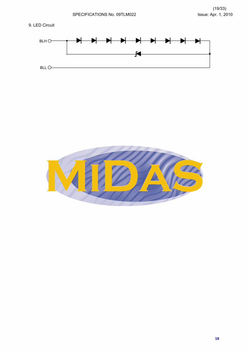
9. LED Circuit
BLH
BLL
19
(20/33)SPECIFICATIONS No. 09TLM022 Issue: Apr. 1, 2010
10. Characteristics
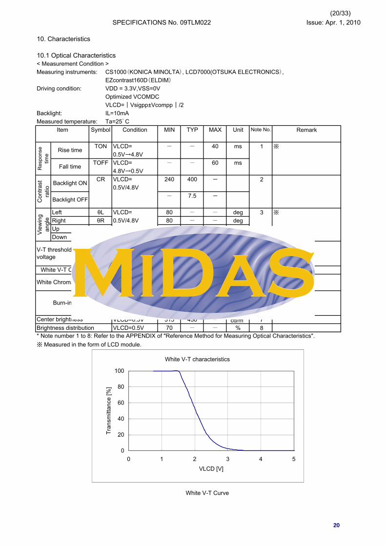
10.1 Optical Characteristics < Measurement Condition >Measuring instruments: CS1000(KONICA MINOLTA), LCD7000(OTSUKA ELECTRONICS),
EZcontrast160D(ELDIM)
Driving condition: VDD = 3.3V,VSS=0VOptimized VCOMDCVLCD=|Vsigpp±Vcompp|/2
Backlight: IL=10mAMeasured temperature: Ta=25゜C
Item Symbol Condition MIN TYP MAX Unit Remark
TON VLCD= - - 40 ms 1 ※
0.5V→4.8VTOFF VLCD= - - 60 ms
4.8V→0.5VCR VLCD= 240 400 - 2
0.5V/4.8V- 7.5 -
Left θL VLCD= 80 - - deg 3 ※
Right θR 0.5V/4.8V 80 - - degUp φU CR≧10 80 - - degDown φD 80 - - deg
V90 1.2 1.5 1.8 V 4 ※
V50 1.7 2.0 2.3 VV10 2.2 2.5 2.8 V
Referencex VLCD=0.5V 5y
6
VLCD=0.5V 315 450 - cd/m2 7Brightness distribution VLCD=0.5V 70 - - % 8
※ Measured in the form of LCD module.
White V-T Curve
Center brightness
* Note number 1 to 8: Refer to the APPENDIX of "Reference Method for Measuring Optical Characteristics".
White V-T Curve
White ChromaticityWhite chromaticity range
Burn-inNo noticeable burn-in image
should be observed after 2 hoursof window pattern display.
Vie
win
gan
gle
V-T thresholdvoltage
White V-T Curve
Con
trast
ratio
Backlight ON
Backlight OFF
Note No.
Res
pons
etim
e
Rise time
Fall time
White V-T characteristics
0
20
40
60
80
100
0 1 2 3 4 5
VLCD [V]
Tran
smitt
ance
[%]
20
(21/33)SPECIFICATIONS No. 09TLM022 Issue: Apr. 1, 2010
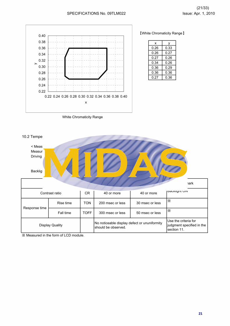
【White Chromaticity Range】
Ta=25゜C0.26 0.330.26 0.270.27 0.260.34 0.260.36 0.290.36 0.360.27 0.36
White Chromaticity Range
10.2 Temperature Characteristics
< Measurement Condition >Measuring instruments: CS1000(KONICA MINOLTA), LCD7000(OTSUKA ELECTRONICS)Driving condition: VDD = 3.3V,VSS=0V
Optimized VCOMDCVLCD=|Vsigpp±Vcompp|/2
Backlight: IL=10mA
Backlight ON
※
※
※ Measured in the form of LCD module.
Display Quality No noticeable display defect or ununiformityshould be observed.
Use the criteria forjudgment specified in thesection 11.
30 msec or less
Fall time TOFF 300 msec or less 50 msec or lessResponse time
Rise time TON 200 msec or less
Contrast ratio CR 40 or more 40 or more
x y
ItemSpecification
RemarkTa=-10゜C Ta=70゜C
0.22
0.24
0.26
0.28
0.30
0.32
0.34
0.36
0.38
0.40
0.22 0.24 0.26 0.28 0.30 0.32 0.34 0.36 0.38 0.40
x
y
21

(22/33)SPECIFICATIONS No. 09TLM022 Issue: Apr. 1, 2010
11. Criteria of Judgment
11.1 Defective Display and Screen Quality
Test Condition: Observed TFT-LCD monitor from front during operation with the following conditionsDriving Signal Raster Patter (RGB in monochrome, white, black)Signal condition VLCD:0.5V, 2.2V, 4.8V (3 steps)Observation distance 30 cmIlluminance 200 to 350 lxBacklight IL=10mA
Uneven brightness on dot-by-dot base due to defective TFT or CF, or dust is counted as dot defect (brighter dot, darker dot)
Point-like uneven brightness (white stain, black stain etc) Invisible through 1% ND filterPoint-like 0.25mm<φ
0.20<φ≦0.25mmφ≦0.20mm
Liner 3.0mm<length and 0.08mm<widthlength≦3.0mm or width≦0.08mm
Use boundary sample for judgment when necessary
φ(mm): Average diameter = (major axis + minor axis)/2Permissible number: N
Table 1
Permissible distance between same color bright dots (includes neighboring dots): 3 mm or morePermissible distance between same color high bright dots (includes neighboring dots): 5 mm or more
<Landscape model>B zone
A zone
1 4 1
Division of A and B areasB area: Active areaDimensional ratio between A and B areas: 1: 4: 1 (Refer to the left figure)
Ignored
N=0N≦2IgnoredN=0
Not exists
Refer to table 1
Defect item Defect content Criteria
Dis
play
Qua
lity
Line defect Black, white or color line, 3 or more neighboring defective dots
Dot defectHigh bright dot: Visible through 2% ND filter at VLCD=4.8VLow bright dot: Visible through 5% ND filter at VLCD=4.8VDark dot: Appear dark through white display at VLCD=2.2V
Scr
een
Qua
lity
Dirt
Foreignparticle
Others
AreaHighbright
dot
Lowbright
dot
Darkdot
A 0 2 2
B 2 4 4
Total 2 4 4
4
1
6
7
Total Criteria
3
1
22
(23/33)SPECIFICATIONS No. 09TLM022 Issue: Apr. 1, 2010
11.2 Screen and Other AppearanceTesting conditions
Observation distance 30cmIlluminance 1200~2000 lx
Flaw Ignore invisible defect when the backlight is on. Applicable area:Stain Active area onlyBubbleDust 3.2 "Outward form")Dent
S-case No functional defect occursFPC cable No functional defect occurs
Item Criteria Remark
Pol
ariz
er
(Refer to the section
23

(24/33)SPECIFICATIONS No. 09TLM022 Issue: Apr. 1, 2010
12. Reliability Testnumber of failures
/number of examinations
Ta=80゜C 240H 0/3Ta=-30゜C 240H 0/3Ta=60゜C,RH=90% 240H 0/3non condensing ※
Tp=70゜C 240H 0/3Tp=-20゜C 240H 0/3Tp=40゜C,RH=90% 240H 0/3non condensing ※
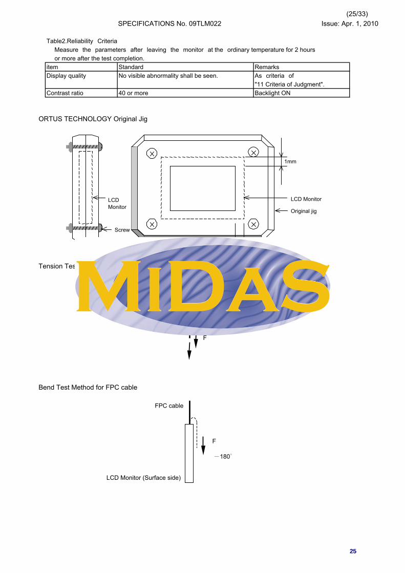
-30←→80゜C(30min/30min) 100 cycles 0/3Confirms to EIAJ ED-4701/300 0/3C=200pF,R=0Ω,V=±200VEach 3 times of discharge on and power supply and other terminals.C=250pF, R=100Ω, V=±12kV 0/3Each 5 times of discharge in both polarities on the center of screen with the case grounded.Pull the FPC with the force of 3N for 10 sec. 0/3in the direction - 90-degree to its original direction.Pull the FPC with the force of 3N for 10 sec. 0/3in the direction -180-degree to its original direction. Reciprocate it 3 times.Total amplitude 1.5mm, f=10~55Hz, X,Y,Z 0/3directions for each 2 hoursoriginal jig (see next 0/3 page) and make an impact with peak acceleration of 1000m/s2 for 6 msec with half sine-curve at3 times to each X, Y, Z directions in conformance with JIS 60068-2-27-1995.Acceleration of 19.6m/s2 with frequency of 0/1 Packing10→55→10Hz, X,Y, Zdirection for each30 minutesDrop from 75cm high. 0/1 Packing1 time to each 6 surfaces, 3 edges, 1 corner
Note:Ta=ambient temperature Tp=Panel temperature
※ The profile of high temperature/humidity storage and High Temperature/humidity operation(Pure water of over 10MΩ・cm shall be used.)
Impact test
Pac
king
test
Packing vibration-proof test
Packing drop test
Mec
hani
cal e
nviro
nmen
tal t
est
Electrostatic discharge test(Non operation)
Surface discharge test(Non operation)
Vibration test
FPC tension test
FPC bend test
Test item Test conditionD
urab
ility
test
High temperature storageLow temperature storageHigh temperature & high
humidity storageHigh temperature operationLow temperature operation
High temp & humid operation
Thermal shock storage
storage:60operation:40
ordinarytemperature 90%RH
0h
0.5h 1h
241h
241.
5h
242h
ordinaryhumidity
25
75%RH60%RH
temperature
relative humidity
24
(25/33)SPECIFICATIONS No. 09TLM022 Issue: Apr. 1, 2010
Table2.Reliability CriteriaMeasure the parameters after leaving the monitor at the ordinary temperature for 2 hoursor more after the test completion.
item Standard RemarksDisplay quality No visible abnormality shall be seen. As criteria of
"11 Criteria of Judgment".Contrast ratio 40 or more Backlight ON
ORTUS TECHNOLOGY Original Jig
Tension Test Method for FPC cable
Bend Test Method for FPC cable
1mm
1mm
LCD Monitor
Original jig
Screw
LCDMonitor
LCD Monitor (Surface side)
-180゜
F
FPC cable
-90°
LCD Monitor (Surface side) FPC cable
F
25
lovickm
Rectangle

(26/33)SPECIFICATIONS No. 09TLM022 Issue: Apr. 1, 2010
13. Packing Specifications
Remark: The return of packing materials is not required.
Tray A-PET AntistaticSealing bagCarton box Corrugated cardboardInner board Corrugated cardboardOuter carton Corrugated cardboardDrier Moisture absorberPacking tape Quantity of products packed in one carton:Extra outer carton Corrugated cardboardFoam sheet PE Anti-static
Gross weight : Approx. 6.7Kg
(338mm)
W : Approx. (549mm)
H : Approx. (198mm)
Dimension of extra outer carton
Packing item name
⑦
D : Approx.
80
⑨
①
Specs., Material
⑥
②
③
④
⑤
⑧
Step 1. Each product is to be placed in one of the cut-outs of the tray with the display surface facing upward. (8products per tray) Foam sheet is put on the products.Step 2. Each tray is to be piled up in same direction and the trays be in a stack of 10. One empty tray is to be put on the top of stack of 10 trays.Step 3. 2 packs of moisture absobers are to be placed on the top tray as shown in the drawing. Put piled trays into a sealing bag. Vacuum and seal the sealing bag with the vacuum sealing machine.Step 4. The stack of trays in the sealing back is to be inserted into a carton box.Step 5. A corrugated board is to be placed in the bottom of an outer carton. The carton box is to be put on the corrugated board in the outer carton. Another corrugated board is to be placed on the top of the inserted carton box.Step 6. The outer carton is to be sealed in H-shape with packing tape as shown in the drawing. The model number, quantity of products, and shipping date are to be printed on the 2 opposite sides of the outer carton with black ink. If necessary, shipping labels or impression markings are to be put on the outer carton.Step 7. The outer carton is to be inserted into an extra outer carton with same direction.Step 8. The extra outer carton is to be sealed in H-shape with packing tape as shown in the drawing. The model number, quantity of products, and shipping date are to be printed on the 2 opposite sides of the outer carton with black ink. If necessary, shipping labels or impression markings are to be put on the extra outer carton.
Packing specification(S=FREE)
26
(27/33)SPECIFICATIONS No. 09TLM022 Issue: Apr. 1, 2010
14. Handling Instruction14.1 Cautions for Handling LCD panels
Caution
(1) Do not make an impact on the LCD panel glass because it may break and you may get injured from it.
(2) If the glass breaks, do not touch it with bare hands.(Fragment of broken glass may stick you or you cut yourself on it.
(3) If you get injured, receive adequate first aid and consult a medial doctor.
(4) Do not let liquid crystal get into your mouth. (If the LCD panel glass breaks, try not let liquid crystal get into your mouth even toxic propertyof liquid crystal has not been confirmed.
(5) If liquid crystal adheres, rinse it out thoroughly.(If liquid crystal adheres to your cloth or skin, wipe it off with rubbing alcohol or washit thoroughly with soap. If liquid crystal gets into eyes, rinse it with clean water for at least 15 minutes and consult an eye doctor.
(6) If you scrape this products, follow a disposal standard of industrial waste that is legally valid in the community, country or territory where you reside.
(7) Do not connect or disconnect this product while its application products is powered on.
(8) Do not attempt to disassemble or modify this product as it is precision component.
(9) If a part of soldering part has been exposed, and avoid contact (short-circuit) with a metallic part of the case etc. about FPC of this model, please. Please insulate it with the insulating tape etc. if necessary. The defective operation is caused, and there is a possibility to generation of heat and the ignition.
(10) Since excess current protection circuit is not built in this TFT module, there is the possibility that LCD module or peripheral circuit become feverish and burned in case abnoramal operation is generated.We recommend you to add excess current protection circuit to power supply.
Caution
This mark is used to indicate a precaution or aninstruction which, if not correctly observed, mayresult in bodily injury, or material damages alone.
!
!
27
(28/33)SPECIFICATIONS No. 09TLM022 Issue: Apr. 1, 2010
14.2 Precautions for Handling
1) Wear finger tips at incoming inspection and for handling the TFT monitors to keep display quality and keep the working area clean.Do not touch the surface of the monitor as it is easily scratched.
2) Wear grounded wrist-straps and use electrostatic neutralization blowers to prevent static charge and discharge when handling the TFT monitors as the LED in this TFT monitors
is damageable to electrostatic discharge,Properly set up equipment, jigs and machines, and keep working area clean and tidy for handling the TFT monitors.
3) Avoid strong mechanical shock including knocking, hitting or dropping to the TFT monitors for protecting their glass parts. Do not use the TFT monitors that have been experienced dropping or strong mechanical shock.
4) Do not use or storage the TFT monitors at high temperature and high humidity environment.
Particularly, never use or storage the TFT monitors at a location where condensation builds up.
5) Avoid using and storing TFT monitors at a location where they are exposed to direct sunlight or ultraviolet rays to prevent the LCD panels from deterioration by ultraviolet rays.
6) Do not stain or damage the contacts of the FPC cable .Otherwise, it may cause poor contact or deteriorate reliability of the FPC cable.
7) Do not bend or pull the FPC cable or carry the TFT monitor by holding the FPC cable.
8) Peel off the protective film on the TFT monitors during mounting process.Refer to the section 14.5 on how to peel off the protective film.We are not responsible for electrostatic discharge failures or other defects occur when peeling off the protective film.
14.3 Precautions for Operation
1) Since this TFT monitors are not equipped with light shielding for the driver IC, do not expose the driver IC to strong lights during operation as it may cause functional failures.
2) When turning off the power, turn off the input signal before or at the same timing of switching off the power.
3) Do not plug in or out the FPC cable while power supply is switch on.Plug the FPC cable in and out while power supply is switched off.
4) Do not operate the TFT monitors in the strong magnetic field. It may break the TFT monitors.
5) Do not display a fixed image on the screen for a long time.Use a screen-saver or other measures to avoid a fixed image displayed on the screen for a long time. Otherwise, it may cause burn-in image on the screen due the characteristics of liquid crystal.
28

(29/33)SPECIFICATIONS No. 09TLM022 Issue: Apr. 1, 2010
14.4 Storage Condition for Shipping Cartons
Storage environment・ Temperature 0 to 40゜C・ Humidity 60%RH or less
・ Atmosphere
・ Time period 3 months・ Unpacking
・ Maximum piling up 7 cartons
14.5 Precautions for Peeling off the Protective film
A) Work Environmenta) Humidity: 50 to 70 %RH, Temperature15 to 27゜Cb) Operators should wear conductive shoes, conductive clothes, conductive finger tips
and grounded wrist-straps. Anti-static treatment should be implemented to work area's floor.c) Use a room shielded against outside dust with sticky floor mat laid
at the entrance to eliminate dirt.
B) Work Method
a) Use an electrostatic neutralization blower to blow air on the TFT monitors to its lower right when the FPC cable is facing to the downside. Optimize direction of the blowing air and the distance between the TFT monitors and the electrostatic neutralization blower.
b) Put an adhesive tape (Scotch tape, etc) at the lower right corner area of the protective film to prevent scratch on surface of TFT monitor.
c) Peel off the adhesive tape slowly (spending more than 2 seconds to complete) by pulling it to opposite direction.
Direction of blowing air(Optimize air direction and the distance)
The following procedures should taken to prevent the driver ICs from charging and discharging.
No-condensing occurs under low temperature with high humidity condition.No poisonous gas that can erode electronic components and/or wiringmaterials should be detected.
To protect the TFT monitors from static damage during unpacking, keep roomhumidity more than 50%RH and implement effective countermeasures againststatic electricity such as establishing a ground (an earth) before unpacking.
The followings work environment and work method are recommended to prevent the TFT monitors fromstatic damage or adhesion of dust when peeling off the protective films.
29
(30/33)SPECIFICATIONS No. 09TLM022 Issue: Apr. 1, 2010
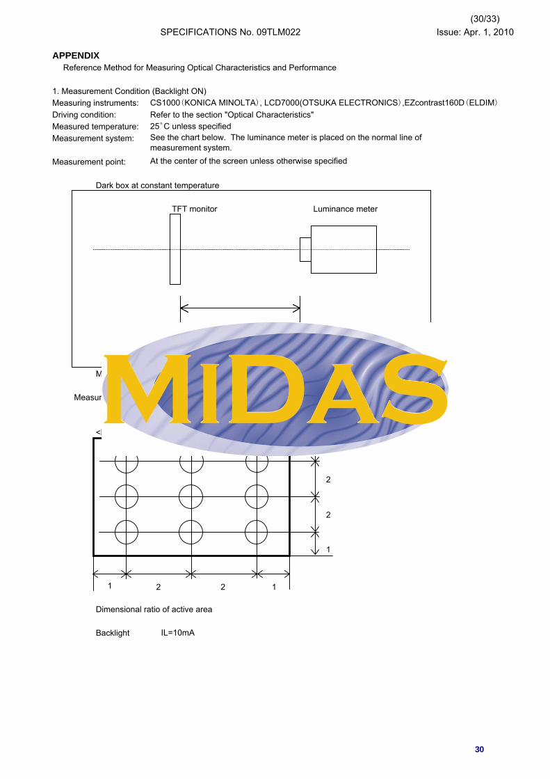
APPENDIXReference Method for Measuring Optical Characteristics and Performance
1. Measurement Condition (Backlight ON)Measuring instruments: CS1000(KONICA MINOLTA), LCD7000(OTSUKA ELECTRONICS),EZcontrast160D(ELDIM)
Driving condition: Refer to the section "Optical Characteristics"Measured temperature: 25゜C unless specifiedMeasurement system:
Measurement point:
Dark box at constant temperature
TFT monitor Luminance meter
LCD7000: 220mmCS1000: 362mm
Measurement is made after 30 minutes of lighting of the backlight.
Measurement point: At the center point of the screenBrightness distribution: 9 points shown in the following drawing.
<Landscape model>1
2
2
1
Dimensional ratio of active area
Backlight IL=10mA
See the chart below. The luminance meter is placed on the normal line ofmeasurement system.At the center of the screen unless otherwise specified
1 2 12
30
(31/33)SPECIFICATIONS No. 09TLM022 Issue: Apr. 1, 2010
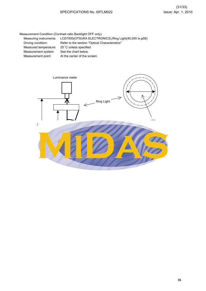
Measurement Condition (Contrast ratio Backlight OFF only)Measuring instruments: LCD7000(OTSUKA ELECTRONICS),Ring Light(40,000 lx,φ58)Driving condition: Refer to the section "Optical Characteristics"Measured temperature: 25゜C unless specifiedMeasurement system: See the chart below. Measurement point: At the center of the screen.
300mm
Luminance meter
TFT monitor
80mm
Ring Light
φ5820°
31

(32/33)SPECIFICATIONS No. 09TLM022 Issue: Apr. 1, 2010
2. Test MethodNotice Item Test method Measuring Remark
instrument1 Response Measure output signal waveform by the luminance LCD7000 Black display
time meter when raster of window pattern is changed from VLCD=4.8Vwhite to black and from black to white. White display
VLCD=0.5VTON
White White Rise time
TOFFWhite Fall time
BlackTON TOFF
2 Measure maximum luminance Y1(VLCD=0.5V) and CS1000 Backlight ONminimum luminance Y2(VLCD=4.8V) at the center of LCD7000 Backlight OFFthe screen by displaying raster or window pattern. Then calculate the ratio between these two values.
Contrast ratio = Y1/Y2Diameter of measuring point: 8mmφ
3 Move the luminance meter from right to left and up EZcontrast160Dand down and determine the angles where contrast ratio is 10.
4 V-T Change VLCD by 0.1V step and plot the points where LCD7000the luminance is 90% as V90, 50% as V50 and 10% as V10 of maximum luminance.
100%
90%
50%
10%0 V90 V50 V10
5 White Measure chromaticity coordinates x and y of CIE1931 CS1000chromaticity colorimetric system at VLCD = 0.5V
Color matching faction: 2°view
Verticalφ
thresholdvalue
Luminance
0%
Contrast ratio
ViewingangleHorizontalθ
Black
100%
90%
10%
32
(33/33)SPECIFICATIONS No. 09TLM022 Issue: Apr. 1, 2010
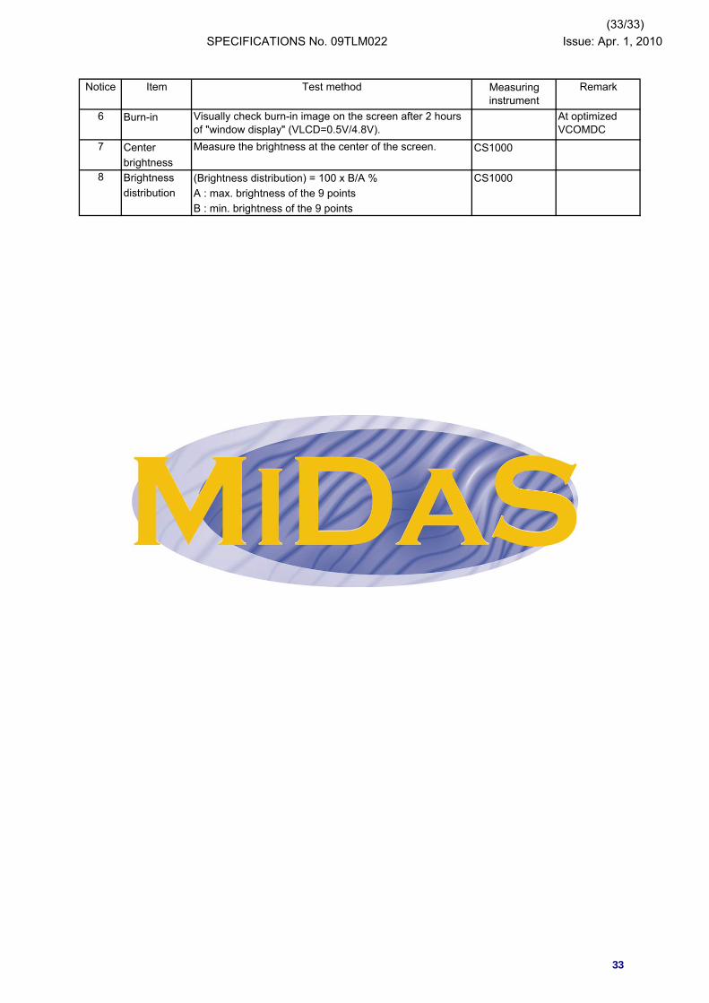
Notice Item Test method Remark
6 Burn-in
7 Center Measure the brightness at the center of the screen. CS1000brightness
8 Brightness (Brightness distribution) = 100 x B/A % CS1000distribution A : max. brightness of the 9 points
B : min. brightness of the 9 points
Measuringinstrument
At optimizedVCOMDC
Visually check burn-in image on the screen after 2 hoursof "window display" (VLCD=0.5V/4.8V).
33
lovickm
Rectangle
lovickm
Rectangle