Additive Manufacturing of Polymer Moulds for Small-Batch ...
6
218 TECHNICAL JOURNAL 14, 2(2020), 218-223 ISSN 1846-6168 (Print), ISSN 1848-5588 (Online) Preliminary communication https://doi.org/10.31803/tg-20200525213336 Additive Manufacturing of Polymer Moulds for Small-Batch Injection Moulding Damir Godec*, Tomislav Breški, Miodrag Katalenić Abstract: In case of small-batch production, applications of classic technologies and tools, for e.g. injection moulding and classic moulds are not competitive. Application of additive technologies (AT) for direct production of finally parts can partially reduce deficiencies of classic approach, but there are for e.g. limited number of available materials. Potential solution is application of AT in production of so called bridge moulds for small-batch production from originally requested material for final part. This paper presents PolyJet process of AT and its possible application for production of bridge polymer moulds for injection moulding of small quantity of the moulded parts together with design rules for PolyJet bridge moulds. Keywords: 3D printing; design rules; PolyJet polymer moulds; small-batch injection moulding 1 INTRODUCTION Modern markets define increased demands on development and production processes. Besides demands on increased product quality, flexibility level in development and production processes, at the same time there are demands on decreasing costs and specially on reducing time for development and production. An additional trend, as a part of megatrends linked with global increasing of human population, and which is highlighted in some segments of global market, is abandoning of mass production and transition to small-batch or even one piece (personalised, custom) production, leading to changes in production paradigm [1]. For fulfilling such demands on the market, since 1980’s additive production (3D printing) processes are in constant development. Main characteristic of this processes is adding material mostly layer-by-layer until production of the final product, based only upon 3D CAD product models, without any need for additional tools (like in case of subtractive or forming processes). Such principle enables production of products with very complex geometrical shapes, which will be very difficult or even impossible to produce by the application of classic technologies. However, despite mentioned advantages, additive manufacturing has certain disadvantages, compared to the classic technologies. First of them, is the limited range of available materials appropriate for additive manufacturing, compared to for example with injection moulding of polymers. Moreover, the physics of making products layer-by-layer is significantly different from physics of classic processes (e.g. injection moulding), resulting in deviations from the expected mechanical and other properties of the products made by additive and classic production processes. In case, when it is necessary to produce certain product in a small series for testing of future products, or for product certification, such deviations are not permissible. For the utilisation of additive manufacturing advantages, possible solution of the mentioned problems can be found in the application of additive manufacturing for production of so-called bridge moulds (tools), which enable production of small series products from original materials with original production processes (e.g. injection moulding). The paper presents PolyJet process of production bridge moulds, specificity of their production and advantages of their application in practise. 2 SYSTEMATISATION OF 3D PRINTED MOULDS The demands on moulds for serial production by injection moulding and the possibilities of additive manufacturing processes are not completely in compliance, therefore direct application of additive manufacturing for injection moulding in the industrial environments still does not have the expected significance despite invested efforts in this field [2, 3]. Rapid Tooling (RT) processes are exposed to far sharper demands compared to Rapid Prototyping (RP) processes. In case of RT processes, produced moulds must stand long-term parameters of e.g. injection moulding (pressures, temperatures, impact loads, shear loads, etc.), they have to be wear resistant, they have to be produced in very narrow tolerances with high surface quality for moulded part aesthetics and for easier moulded part ejection from the mould cavity. When durability of the moulds (mould inserts) for injection moulding becomes important, 3D printed moulds are divided into three groups: • soft (temporary) tools/moulds, • bridge tools/moulds, • hard tools/moulds. In case of soft moulds, only a few moulded parts can be produced within such moulds, before the moulds are worn or damaged. An example of this type of moulds is a silicone mould (Fig. 1). The main advantage of this tooling approach is that such moulds can be produced within one day. A small-batch production of dozen to a few thousand parts can be run with so-called bridge moulds (Fig. 2). Final number of produced moulded parts depends on applied materials (paper, metal, polymers ...). Bridge moulds also can be produced in relatively short time (from one to few days), which also depends on applied materials and additive technologies.
Transcript of Additive Manufacturing of Polymer Moulds for Small-Batch ...

218 TECHNICAL JOURNAL 14, 2(2020), 218-223
ISSN 1846-6168 (Print), ISSN 1848-5588 (Online) Preliminary communication https://doi.org/10.31803/tg-20200525213336
Additive Manufacturing of Polymer Moulds for Small-Batch Injection Moulding
Damir Godec*, Tomislav Breški, Miodrag Katalenić
Abstract: In case of small-batch production, applications of classic technologies and tools, for e.g. injection moulding and classic moulds are not competitive. Application of additive technologies (AT) for direct production of finally parts can partially reduce deficiencies of classic approach, but there are for e.g. limited number of available materials. Potential solution is application of AT in production of so called bridge moulds for small-batch production from originally requested material for final part. This paper presents PolyJet process of AT and its possible application for production of bridge polymer moulds for injection moulding of small quantity of the moulded parts together with design rules for PolyJet bridge moulds. Keywords: 3D printing; design rules; PolyJet polymer moulds; small-batch injection moulding 1 INTRODUCTION
Modern markets define increased demands on development and production processes. Besides demands on increased product quality, flexibility level in development and production processes, at the same time there are demands on decreasing costs and specially on reducing time for development and production. An additional trend, as a part of megatrends linked with global increasing of human population, and which is highlighted in some segments of global market, is abandoning of mass production and transition to small-batch or even one piece (personalised, custom) production, leading to changes in production paradigm [1]. For fulfilling such demands on the market, since 1980’s additive production (3D printing) processes are in constant development. Main characteristic of this processes is adding material mostly layer-by-layer until production of the final product, based only upon 3D CAD product models, without any need for additional tools (like in case of subtractive or forming processes). Such principle enables production of products with very complex geometrical shapes, which will be very difficult or even impossible to produce by the application of classic technologies. However, despite mentioned advantages, additive manufacturing has certain disadvantages, compared to the classic technologies. First of them, is the limited range of available materials appropriate for additive manufacturing, compared to for example with injection moulding of polymers. Moreover, the physics of making products layer-by-layer is significantly different from physics of classic processes (e.g. injection moulding), resulting in deviations from the expected mechanical and other properties of the products made by additive and classic production processes. In case, when it is necessary to produce certain product in a small series for testing of future products, or for product certification, such deviations are not permissible. For the utilisation of additive manufacturing advantages, possible solution of the mentioned problems can be found in the application of additive manufacturing for production of so-called bridge moulds (tools), which enable production of small series products from original materials
with original production processes (e.g. injection moulding). The paper presents PolyJet process of production bridge moulds, specificity of their production and advantages of their application in practise. 2 SYSTEMATISATION OF 3D PRINTED MOULDS
The demands on moulds for serial production by injection moulding and the possibilities of additive manufacturing processes are not completely in compliance, therefore direct application of additive manufacturing for injection moulding in the industrial environments still does not have the expected significance despite invested efforts in this field [2, 3]. Rapid Tooling (RT) processes are exposed to far sharper demands compared to Rapid Prototyping (RP) processes. In case of RT processes, produced moulds must stand long-term parameters of e.g. injection moulding (pressures, temperatures, impact loads, shear loads, etc.), they have to be wear resistant, they have to be produced in very narrow tolerances with high surface quality for moulded part aesthetics and for easier moulded part ejection from the mould cavity.
When durability of the moulds (mould inserts) for injection moulding becomes important, 3D printed moulds are divided into three groups: • soft (temporary) tools/moulds, • bridge tools/moulds, • hard tools/moulds.
In case of soft moulds, only a few moulded parts can be produced within such moulds, before the moulds are worn or damaged. An example of this type of moulds is a silicone mould (Fig. 1). The main advantage of this tooling approach is that such moulds can be produced within one day.
A small-batch production of dozen to a few thousand parts can be run with so-called bridge moulds (Fig. 2). Final number of produced moulded parts depends on applied materials (paper, metal, polymers ...). Bridge moulds also can be produced in relatively short time (from one to few days), which also depends on applied materials and additive technologies.

Damir Godec et al.: Additive Manufacturing of Polymer Moulds for Small-Batch Injection Moulding
TEHNIČKI GLASNIK 14, 2(2020), 218-223 219
Figure 1 Soft (silicone) mould [4]
Figure 2 Bridge (PolyJet) mould [5]
Finally, with hard moulds (Fig. 3) it is possible to
produce a few hundred thousand moulded parts. Their durability is similar to the moulds produces in conventional ways, but they require much more time and expenses for production, compared to the soft and bridge moulds.
Figure 3 Hard metal mould insert [6]
3 PolyJet ADDITIVE TECHNOLOGY
According to the standard ISO/ASTM 52900 [7], all processes of Additive Manufacturing are divided into 7 categories: binder jetting, direct energy deposition, material extrusion, material jetting, powder bed fusion, sheet lamination and vat photo-polymerisation. The PolyJet process belongs to the material jetting processes of additive manufacturing. Generally, the PolyJet process consists of jetting a thin layer of photosensitive polymer material(s) (acrylic resins) in the form of fine droplets through a head with a nozzle grid, followed by curing with a source of UV light (UV lamp) (Fig. 4).
In the return path of the printing head, a small cutter will remove small bulging at the top of the layer which results in spreading the material in the form of droplets, obtaining a more accurate layer thickness.
Figure 4 PolyJet process principle [1, 2]
The layer thickness can be set to 16 µm or 32 µm. While
jetting one layer, during the production complex parts, the 3D printer uses both, model and support materials [1] (Fig. 5).
Figure 5 PolyJet process - Printing of built and support material [2]
After finishing one layer, the build platform is lowered
down for next layer thickness and the process is repeated until finishing the part. After removing the finished part from the build platform, the support material should be removed from the finished 3D printed part (e.g. with water jetting).
The main advantage of the PolyJet process is the ability to cure the whole layer at the same time, which is much faster compared to some processes that use selective curing on the working layer (e.g. like Stereolithography). The PolyJet process is very accurate, and as it uses model materials in liquid form, a small surface roughness can be achieved. Therefore demands for additional treatment of PolyJet 3D printed parts are minimal. Also, as each layer is fully cured during the printing process, there is no need for additional curing after 3D printing [1]. Second generation of PolyJet printers enabled application of two different types of basic acrylic resins as built materials at the same time in a process called PolyJet Matrix. The PolyJet Matrix process works by simultaneously jetting two distinct photopolymer built materials in pre-set combinations (previously prepared and separated in the STL file). The dual-jet process combines these materials to produce multi-material parts and create new composite materials, called Digital Materials [8]. 3.1 PolyJet Technology for Production of Temporary/Bridge
Moulds
PolyJet moulds for injection moulding are not intended to be a replacement for soft or hard tools used in mid- and high volume production. Instead, they are intended to fill the

Damir Godec et al.: Additive Manufacturing of Polymer Moulds for Small-Batch Injection Moulding
220 TECHNICAL JOURNAL 14, 2(2020), 218-223
gap between soft and hard moulds as well as a substitute for 3D printed prototypes [1].
In cases where design changes are required, a new iteration of the mould can be created in-house at minimal cost. This, combined with the speed of the PolyJet 3D printing, allows designers and engineers greater design freedom. Complex geometries of moulded parts and moulds do not represent any limitation in PolyJet mould manufacturing. Moreover, for this process NC programming is not needed, and manufacturing is based only on mould CAD model [1].
Fig. 6 shows a comparison of moulds produced with PolyJet technology and moulds produced with classic technologies from common mould materials and AM technologies for production of metal bridge/hard moulds. It has to be stressed that A and B processed materials (e.g. unreinforced polyolefins) are far less aggressive, and C and D groups are more aggressive materials for mould cavity wall wearing (e.g. reinforced polymers) [9].
Figure 6 Anticipated number of produced parts depending on the type of the mould
and material class [9]
Some of typical polymer materials which can be processed in PolyJet moulds regarding Fig.6 are: A Polyethylene (PE)
Polypropylene (PP) Polystyrene (PS) Acrylonitrile Butadiene Styrene (ABS) Thermoplastic elastomer (TPE)
B Fiber glass filled Polyproylene (PP+G) Acetal (Polyoxymethylene - POM) Polycarbonate-ABS blend (PC+ABS)
C Polycarbonate (PC) Fiber glass filled Acetal (POM+G) Polyamide (PA)
D Fiber glass filled Polycarbonate (PC+G) Fiber glass filled Polyamide (PA+G) Polyphenylene Oxide (PPO) Polyphenylene Sulfide (PPS).
3.2 Materials for PolyJet Production of Bridge Moulds
PolyJet and PolyJet Matrix processes enable the application of more than one hundred different materials based on acrylic resins, which can mimics the properties of
the materials from elastic to rigid. For manufacturing bridge moulds, mould material have to be strong enough (tensile, flexural, compressive and bending strength), tough, and resistant to high temperatures to maintain mould cavity dimensions. Four materials can be separate as the most appropriate for the PolyJet bridge mould manufacturing: RGD 525 (white high-temperature material) and RGD 5160-DM, RGD 5161-DM and Digital ABS plus (ABS-like green materials). Tab. 1 shows some basic mechanical and thermal properties of those materials.
Table 1 Properties of PolyJet materials suitable for mould production [10, 11]
Property/(unit) RGD 525 RGD 5160-DM RGD 5161-DM
Digital ABS plus
Tensile strength/(MPa) 70-80 55-60 55-60 Tensile modulus/(MPa) 3200-3500 2600-3000 2600-3000 Flexural strength/(MPa) 110-130 65-75 65-75 Flexural modulus/(MPa) 3100-3500 1700-2200 1700-2200 Izod impact strength/(J/m) 14-16 65-80 90-115 Heat deflection temperature/(°C) 63-67 58-68 58-68
Heat deflection temperature (after hardening)/(°C) 75-80 92-95 92-95
Material RGD 525 is the strongest material, but its
toughness is 5 to 7 times lower compared to the other materials. RGD-5160-DM is suitable for production of details with wall thickness down to 1,5 mm, while RGD-5161-DM for wall thickness down to 1,0 mm. If the highest impact resistant and shock absorption are requested, Digital ABS plus is the most appropriate. With hardening process in furnace (Fig. 7), heat deflection temperature can be increased for all materials up to 30 %.
Figure 7 Process of mould insert hardening [12]
Increasing of heat deflection temperature is very
important in application for mould inserts for injection moulding, where mould material is heated in cycles as hot polymer melt fills the mould cavity. 4 DESIGN RULES FOR BRIDGE POLYJET MOULDS
While design of bridge PolyJet moulds, it is possible to apply basic guidelines for design of classic moulds for injection moulding. However, because of specific PolyJet materials properties for production of bridge moulds, it is necessary to make some modifications in design concept.

Damir Godec et al.: Additive Manufacturing of Polymer Moulds for Small-Batch Injection Moulding
TEHNIČKI GLASNIK 14, 2(2020), 218-223 221
This is necessary because of compensation of mechanical, thermal and dimensional characteristics of such plastic moulds. Some of the basic rules for design of PolyJet bridge moulds are [5]: • increase the draft angles for easier moulded part ejection
(Fig. 8),
Figure 8 Increased draft angles [5]
• at all sharp edges add minimal radius, • for building a 3D printed mould into a classic mould
base, add at least 0,2 mm in height at the back face to improve mould closing and avoiding of flash (Fig. 9),
Figure 9 Extension of the back face of the core/cavity [5]
• while 3D printing of the core pin, it is recommended
height/width aspect ratio of 3:1 (for larger aspect ratio it is recommended to use exchangeable metallic pins),
• while making holes, minimal diameter is 0,8 mm, • for mould gate design, classic side, film, tab and ring
gates are recommended (avoid tunnel and pin gates) (Fig. 10),
Figure 10 Typical bridge mould side gate [5]
• gate dimensions have to be 2-3 times larger than gate dimensions in classic steel moulds,
• gate thickness has to be equal or larger than maximal moulded part wall thickness,
• metallic sprue has to be built into plastic mould, in order to avoid direct contact of the plastic mould with hot injection moulding machine nozzle,
• build in classic ejector pins that are not placed on distances smaller than 3 mm from the mould cavity edge (otherwise, the mould can be damaged) (Fig. 11),
Figure 11 Moulded part ejection system [5]
• decrease the ejector holes diameters for 0,2 to 0,3 mm
and adjust them for the ejector mounting into the mould insert with classical machining,
• complex mould cavity geometry has to be split into multiple mould inserts (Fig. 12), in order to achieve appropriate mould cavity venting through tolerances in inserts contact,
Figure 12 Multiply mould inserts [5]
• although, because of poor thermal conductivity of
PolyJet materials, classic mould tempering by cooling channels and water as a coolant is not efficient, avoiding it can contribute to prolongation of the mould durability (expected up to 20 %) (Fig. 13),
• more effective cooling is done by blowing of compressed air on the mould parting plane,

Damir Godec et al.: Additive Manufacturing of Polymer Moulds for Small-Batch Injection Moulding
222 TECHNICAL JOURNAL 14, 2(2020), 218-223
Figure 13 Cooling channels plugs [5]
• while preparing for 3D printing, mould insert should be
oriented so that the mould cavity is up-oriented (glossy surface without support material), which will result with smoother mould cavity surface (Fig. 14),
Figure 14 Orientation for glossy surface without support material [5]
• mould insert should be oriented on the building platform
with larger dimension in line with the printing head moving direction (print lines) because in that orientation the material is better cured - it is longer exposed to the UV light (Fig. 15).
Figure 15 Orientation along printing line [12]
5 POSSIBILITIES OF PolyJet BRIDGE MOULDS
APPLICATION In the application of bridge PolyJet mould inserts, several approaches in embedding in standard mould bases or their independent application are possible. In the case of
smaller injection moulded parts, it is possible to independently use PolyJet bridge moulds. Depending on the application of hand or mechanical injection moulding machines (Fig. 16), it is necessary to adjust PolyJet moulds dimensions correspondingly.
Figure 16 Bridge mould on injection moulding machine [4]
In the case of using a hand injection moulding machine,
the designer has larger freedom in mould design and optimising its dimensions (Fig. 17).
Figure 17 PolyJet mould for applications on hand-injection moulding machine [13]
When PolyJet moulds are applied on mechanical injection moulding machines, it is necessary to adjust mould dimensions to the injection moulding machine clamping plates and tie bars, as well as the rest of the mould base. Besides, it is necessary to enlarge the thickness of the mould plates, compared to the moulds aimed to operate with hand injection moulding machines, in order to avoid creation of cracks on the mould plates (Fig. 18).
Figure 18 PolyJet mould plate with cracks [14]
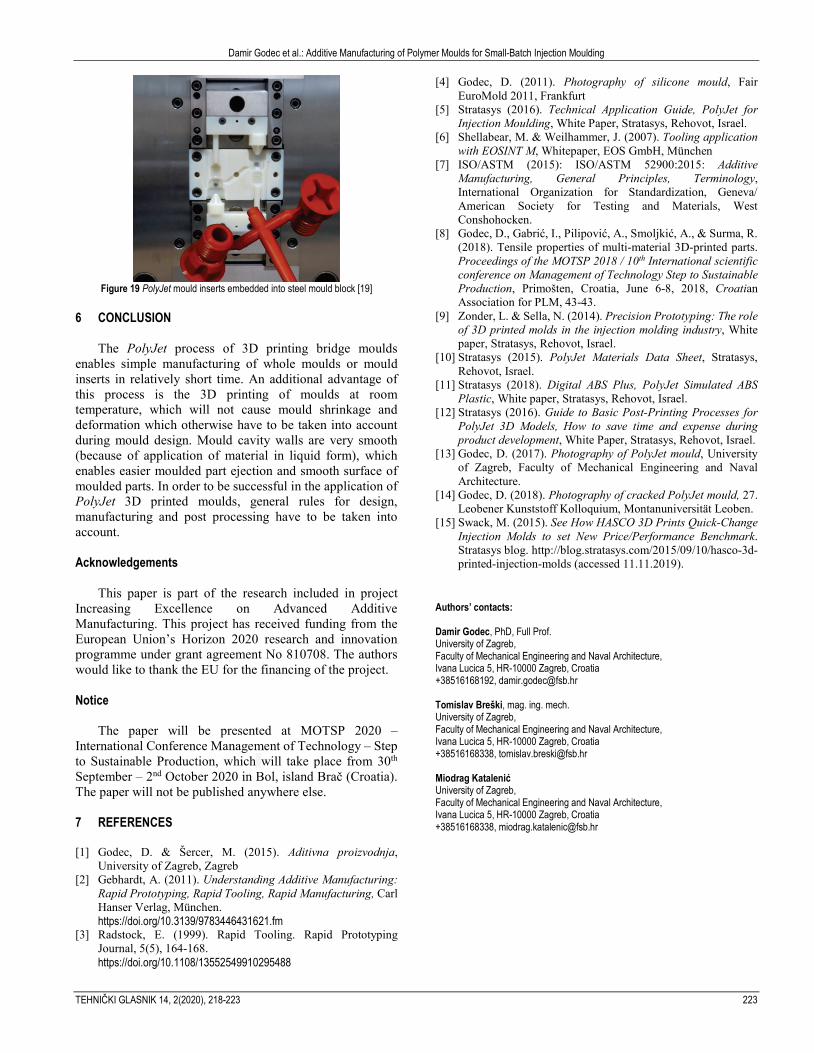
In the case of the production of large amount of moulded
parts on larger injection moulding machines, PolyJet mould inserts have to be embedded into a steel mould base (Fig. 19).
Damir Godec et al.: Additive Manufacturing of Polymer Moulds for Small-Batch Injection Moulding
TEHNIČKI GLASNIK 14, 2(2020), 218-223 223
Figure 19 PolyJet mould inserts embedded into steel mould block [19]
6 CONCLUSION
The PolyJet process of 3D printing bridge moulds enables simple manufacturing of whole moulds or mould inserts in relatively short time. An additional advantage of this process is the 3D printing of moulds at room temperature, which will not cause mould shrinkage and deformation which otherwise have to be taken into account during mould design. Mould cavity walls are very smooth (because of application of material in liquid form), which enables easier moulded part ejection and smooth surface of moulded parts. In order to be successful in the application of PolyJet 3D printed moulds, general rules for design, manufacturing and post processing have to be taken into account. Acknowledgements
This paper is part of the research included in project Increasing Excellence on Advanced Additive Manufacturing. This project has received funding from the European Union’s Horizon 2020 research and innovation programme under grant agreement No 810708. The authors would like to thank the EU for the financing of the project. Notice
The paper will be presented at MOTSP 2020 – International Conference Management of Technology – Step to Sustainable Production, which will take place from 30th September – 2nd October 2020 in Bol, island Brač (Croatia). The paper will not be published anywhere else. 7 REFERENCES [1] Godec, D. & Šercer, M. (2015). Aditivna proizvodnja,
University of Zagreb, Zagreb [2] Gebhardt, A. (2011). Understanding Additive Manufacturing:
Rapid Prototyping, Rapid Tooling, Rapid Manufacturing, Carl Hanser Verlag, München.
https://doi.org/10.3139/9783446431621.fm [3] Radstock, E. (1999). Rapid Tooling. Rapid Prototyping
Journal, 5(5), 164-168. https://doi.org/10.1108/13552549910295488
[4] Godec, D. (2011). Photography of silicone mould, Fair EuroMold 2011, Frankfurt
[5] Stratasys (2016). Technical Application Guide, PolyJet for Injection Moulding, White Paper, Stratasys, Rehovot, Israel.
[6] Shellabear, M. & Weilhammer, J. (2007). Tooling application with EOSINT M, Whitepaper, EOS GmbH, München
[7] ISO/ASTM (2015): ISO/ASTM 52900:2015: Additive Manufacturing, General Principles, Terminology, International Organization for Standardization, Geneva/ American Society for Testing and Materials, West Conshohocken.
[8] Godec, D., Gabrić, I., Pilipović, A., Smoljkić, A., & Surma, R. (2018). Tensile properties of multi-material 3D-printed parts. Proceedings of the MOTSP 2018 / 10th International scientific conference on Management of Technology Step to Sustainable Production, Primošten, Croatia, June 6-8, 2018, Croatian Association for PLM, 43-43.
[9] Zonder, L. & Sella, N. (2014). Precision Prototyping: The role of 3D printed molds in the injection molding industry, White paper, Stratasys, Rehovot, Israel.
[10] Stratasys (2015). PolyJet Materials Data Sheet, Stratasys, Rehovot, Israel.
[11] Stratasys (2018). Digital ABS Plus, PolyJet Simulated ABS Plastic, White paper, Stratasys, Rehovot, Israel.
[12] Stratasys (2016). Guide to Basic Post-Printing Processes for PolyJet 3D Models, How to save time and expense during product development, White Paper, Stratasys, Rehovot, Israel.
[13] Godec, D. (2017). Photography of PolyJet mould, University of Zagreb, Faculty of Mechanical Engineering and Naval Architecture.
[14] Godec, D. (2018). Photography of cracked PolyJet mould, 27. Leobener Kunststoff Kolloquium, Montanuniversität Leoben.
[15] Swack, M. (2015). See How HASCO 3D Prints Quick-Change Injection Molds to set New Price/Performance Benchmark. Stratasys blog. http://blog.stratasys.com/2015/09/10/hasco-3d-printed-injection-molds (accessed 11.11.2019).
Authors’ contacts: Damir Godec, PhD, Full Prof. University of Zagreb, Faculty of Mechanical Engineering and Naval Architecture, Ivana Lucica 5, HR-10000 Zagreb, Croatia +38516168192, [email protected] Tomislav Breški, mag. ing. mech. University of Zagreb, Faculty of Mechanical Engineering and Naval Architecture, Ivana Lucica 5, HR-10000 Zagreb, Croatia +38516168338, [email protected] Miodrag Katalenić University of Zagreb, Faculty of Mechanical Engineering and Naval Architecture, Ivana Lucica 5, HR-10000 Zagreb, Croatia +38516168338, [email protected]