Additional Agenda‐I for 19th Standing Committee … · Additional Agenda‐I for 19th Standing...
43
1
-
Upload
vuongnguyet -
Category
Documents
-
view
223 -
download
3
Transcript of Additional Agenda‐I for 19th Standing Committee … · Additional Agenda‐I for 19th Standing...
1
2

AdditionalAgenda‐Ifor19thStandingCommitteeMeetingonPowerSystemPlanningofER
Additional Agenda-I for 19th Standing Committee Meeting on Power System Planning of Eastern Region
1.0 Upgradation of 132kV bus arrangement at 400/220/132kV Malda S/s of POWERGRID
1.1 POWERGRID has proposed the following:
1.1.1 Presently, Single Main & Transfer (SMT) scheme is functional at 132kV level and Double Main & Transfer (DMT) scheme at 400kV & 220kV levels at Malda S/s.
1.1.2 The transformation capacity at Malda S/S at 220/132kV is being upgraded from 370MVA (2x160MVA+1x50MVA) to 480MVA (3x160MVA) under ERSS-XX. The Malda 132kV main bus is of Single Moose Conductor. Due to increased loading at 132kV level, problems in the main bus are being encountered more often. Malda (POWERGRID) – Malda (WBSETCL) 132kV D/c line has been reconductored from Panther (ACSR) to Casablanca (ACCC) by WBSETCL, thereby increasing current carrying capacity from 366A to 1120A per circuit . In the 18th ER-SCM, it was agreed that WBSETCL may terminate Malda (WBSETCL) – Samsi 132kV S/c line at Malda (POWERGRID) as an interim measure before summer of 2017 to relieve the loading on Malda (POWERGRID) – Malda (WBSETCL) 132kV D/c line.
1.1.3 Malda is an important substation in northern part of West Bengal which remains critically loaded at 132kV level. With SMT scheme, complete shutdown of 132kV bus is required for maintenance works in the main bus. Thus, keeping in view the importance of Malda S/s and in order to improve reliability at 132kV level, bus arrangement including switchgear are proposed to be upgraded to Double Main (DM) scheme by POWERGRID, in a similar manner as being implemented at Siliguri and Birpara 132kV level under other schemes. Due to space constraints, the upgradation work needs to be carried out through GIS bays.
1.2 CEA’s observations on the above proposal are:
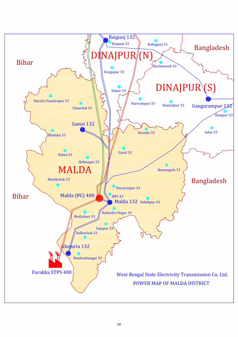
1.2.1 Approved Gazol sub-station is about 14km from existing Malda 400/220/132kV substation (POWERGRID). Gazol 220/132kV Sub-station (2x160MVA) with the LILO of Malda-Dalkhola 220kV D/C line of POWERGRID was approved in 2nd-2013 meeting of the Standing Committee on Power System Planning of Eastern Region(15th SCMPSP-ER) held on 27.08.2013. Proposed and existing power map of Malda district is at Annexure- 1.1. Therefore reliability of power supply increases in Malda district with the commissioning of Gazol Sub-station with associated lines.
1.2.2 Bus maintenance is not required frequently and requires few hours of shutdown, which can be planned during off-peak hours and during that period the power could be supplied to Malda district through Gazol sub station.
3

AdditionalAgenda‐Ifor19thStandingCommitteeMeetingonPowerSystemPlanningofER
1.2.3 SMT scheme is having advantage of carrying out breaker maintenance without shutdown/outage of corresponding load/ICT, which is not possible in the proposed DM (Double Main) Bus scheme.
1.3 Members may deliberate.
2.0 Modification under 13th Plan scheme: Agenda by BSPTCL
2.1 BSPTCL has informed that to meet the future demand of Bihar by 2021-22, Sitamarhi, Chandauti and Saharsa (New) substations were approved under ISTS in the 18th ER-SCM held on 13-06-2016. The scheme is being implemented through TBCB under ERSS-21 (under bidding stage). Therein scope of Sitamarhi (New) & Saharsa (New) S/s inter alia includes following:
2.2 Sitamarhi(New) S/s: 400/220/132kV, 2x500MVA + 2x200MVA
(a) Darbhanga – Sitamarhi(New) 400kV D/c (Triple Snowbird)(b) Sitamarhi(New) – Motihari 400kV D/c (Triple Snowbird)(c) Sitamarhi(New) – Motipur 220kV D/c(d) Sitamarhi (New) – Sitamarhi 132kV D/c (Single Moose)(e) Sitamarhi(New) – Pupri 132kV D/c
2.3 Saharsa (New) 400/220/132kV S/s: 2x500MVA + 2x200MVA
(a) LILO of Kishanganj – Patna 400kV D/c (Quad) at Saharsa (New)(b) Saharsa (New) – Begusarai 220kV D/c(c) Saharsa (New) – Khagaria (New) 220kV D/c(d) Saharsa (New) – Saharsa 132kV D/c (Single Moose)
2.4 However, due to space constraints for additional line bays and unavailability of corridor some modifications are required in the 13th plan scheme. A joint load flow study has been carried out with POWERGRID and following modification is proposed in the intra-state portion (under scope of BSPTCL):
Sl.No.
400/200/132 kV New Sub-station
Original Scope Proposed
Modification Justification
1 Sitamarhi (New)
Sitamarhi (New) – Sitamarhi 132kV D/c (Single moose)
Sitamarhi (New) – Runnisaidpur 132kV D/c
Space is not available for new line bay as well as corridor is not available for line termination at 132kV Sitamarhi (old) GSS.
Sitamarhi (New) – Pupri 132kV D/c
LILO of Benipatti - Pupri 132 kV S/c at Sitamarhi (New)
Severe ROWs and Densely populated area around Grid Substation, Pupri
2 New Line Vaishali – Hazipur 132kV D/c
Vaishali – Chapra (New) (Amnour) 132kV D/c
No corridor available at entry point of 220/132kV GSS Hajipur and severe ROW problems due to dense population.
4

AdditionalAgenda‐Ifor19thStandingCommitteeMeetingonPowerSystemPlanningofER
Sl.No.
400/200/132 kV New Sub-station
Original Scope Proposed
Modification Justification
3 Saharsa (New)
Saharsa (New) – Saharsa 132kV D/c (Single Moose)
LILO of Saharsa (BSPTCL) – Banmankhi 132kV S/c line at Saharsa (New) 400/220/132 kV
As reported by field office, Space is not available for new line bay at 132/33 kV Saharsa (old) GSS of BSPTCL as well as corridor is not available
LILO of Saharsa (BSPTCL) – Udakishanganj 132kV S/c line at Saharsa(New) 400/220/132 kV
Stringing of 2nd
circuit of Saharsa (Old) – Sonebarsa (formed after LILO of Madhupura – Sonebarsa 132kV S/c on D/c line at Saharsa (Old)) 132kV S/c on D/c line section
LILO of one of the circuit of Madhupura – Sonebarsa 132kVD/c line atSaharsa(New)400/220/132 kV[one circuit is alreadybeing LILOed atSaharsa (BSPTCL),the other circuit is tobe LILOed atSaharsa (New)400/220/132 kV]
4 Stringing of 2nd
Circuit
Stringing of 2nd circuit of Muzaffarpur – SKMCH 132kV S/c on D/c
Reconductoring of 132kV S/c Muzaffarpur – SKMCH lines with HTLS of 240MVA (1050A ampacity)
The existing 132kV Muzaffarpur – SKMCH Tr. Line is single circuit single strung.
2.5 Scope to be deleted
1. Sitamarhi (New) – Sitamarhi 132kV D/c (Single Moose).2. Sitamarhi (New) – Pupri 132kV D/c.3. Vaishali – Hazipur 132kV D/c.4. Stringing of 2nd circuit of Muzaffarpur – SKMCH 132kV S/c on D/c.5. Saharsa (New) – Saharsa 132kV D/c (Single Moose).6. Stringing of 2nd circuit of Saharsa (Old) – Sonebarsa (formed after LILO of
Madhupura – Sonebarsa 132kV S/c on D/c line at Saharsa (Old)) 132kVS/c on D/c line section.
7. Nos. of 132 kV Line bays at Saharsa (New) S/s: 2 nos.[2 no. for Saharsa (New) – Saharsa 132kV D/c (Single Moose) line]
2.6 Scope to be Added
1. 400/220/132 kV Sitamarhi (New) – Runnisaidpur 132kV D/c.
5

AdditionalAgenda‐Ifor19thStandingCommitteeMeetingonPowerSystemPlanningofER
2. LILO of Benipatti - Pupri 132 kV S/c at Sitamarhi (New) 400/220/132 kV. 3. Vaishali – Chapra (New) (Amnour) 132 kV D/c. 4. Reconductoring of 132kV S/c Muzaffarpur – SKMCH lines with HTLS of
240MVA (1050A ampacity). 5. LILO of 132/33 kV Saharsa (Old) BSPTCL – Banmankhi 132kV S/c line at
Saharsa (New) 400/220/132 kV. 6. LILO of 132/33 kV Saharsa (Old) BSPTCL – Udakishanganj 132kV S/c
line at Saharsa (New) 400/220/132 kV. 7. LILO of one of the circuit of Madhupura – Sonebarsa 132kV D/c line at
Saharsa (New) 400/220/132 kV. [one circuit is already being LILOed at Saharsa (BSPTCL), the other circuit is to be LILOed at Saharsa (New) 400/220/132 kV]
8. Nos. of 132 kV Line bays at Saharsa (New) S/s: 6 nos. [2 no. for LILO of each of the following 132kV lines at Saharsa (New):
i. LILO of Saharsa (BSPTCL) – Banmankhi. ii. LILO of Saharsa (BSPTCL) – Udakishanganj. iii. LILO of one circuit of Madhupura – Sonebarsa.]
2.7 BSPTCL informed that after above modification 6 nos. 132 KV bays are required at Saharsa (New) Substation (400/220/132 KV, 2x500+2x200 MVA) whereas 2 nos. of 132 KV bays were approved at the Saharsa (New) Substation. Therefore, BSPTCL requested RECTPCL (Bid Process Coordinator for ERSS-XXI) to include the 6 nos. of 132 KV bays instead of 2 nos. of 132 KV bays at Saharasa (new) and accordingly scope of work could be modified.
2.8 Members may deliberate.
3.0 To provide one additional 500MVA transformer at Patna (PG): Agenda by BSPTCL
3.1 BSPTCL has informed that the power demand of Patna and surrounding area is increasing very fast. The load requirement of central and eastern Patna is substantial due to presence of various commercial, institutional & educational establishments, and dense urban population. The load demand is largely fed by Patna (PG) with the installed capacity of 1X500 MVA + 1X315 MVA (to be changed by 500 MVA). The connected load to the above GSS is as follows:-
(a) 220/132 KV GSS Gaurichak – 1X160 + 2X150 MVA = 460 MVA (b) 220/132/33 kV GSS Khagaul – 4X100 MVA = 400 MVA (c) 220/132/33 kV GSS Fatuha – 5X100 MVA = 500 MVA (d) 220/132/33 kV Bihta (New) – 2X160 MVA = 320 MVA (Likely to be
commissioned at the end of 2017).
3.2 The capacity of Patna (PG) is very critical. The average load at present on Patna (PG) is 550 MW and the peak load is 650 MW, which may increase to 820MW in the coming year so it is not fulfilling N-1 criteria. As it happened on
6

AdditionalAgenda‐Ifor19thStandingCommitteeMeetingonPowerSystemPlanningofER
03.07.2017, one 500MVA transformer tripped on fault, as a result another 315 MVA transformer also tripped on overload and the major part of the state capital faced total blackout on that day.
3.3 In view of the above facts, CEA is requested to look upon this issue of installation of additional 1X500MVA power transformer at Patna (PG) under N-1 scheme to ensure uninterrupted power to state capital in the event of outage of one of the transformer.
3.4 Members may deliberate.
4.0 Bus and Bay strengthening at Purnea (PG): Agenda by BSPTCL
4.1 BSPTCL has informed that recondutoring of 132 kV Purnea (PG) – Purnea (BSPTCL) (T/C) transmission line from Panther to HTLS conductor has already been completed and line is charged. Now each circuit capacity is 1000 Amp i.e. 200 MW.
4.2 It has been planned to test the line for its loading, which requires compatibility of 132 kV main bus bar, bay etc. at both Purnea (PG) and Purnea (BSPTCL) GSS ends.
4.3 In BSPTCL for Purnea GSS end, order has been awarded for R&M of GSS, which includes the work of bus bar & bay strengthening. These works are expected to be completed by 31.08.2017.
4.4 For drawing optimum power from Purnea (PG) end, bus & bay equipment must be capable to sustain load. The matter was discussed in 134th OCC meeting held on 11.07.2017 at ERPC, Kolkata also.
4.5 POWERGRID vide its letter dated 10-08-2017 has clarified that, in order to improve reliability of 132kV system at Purnea (POWERGRID) 220/132kV S/s, the 132kV bus scheme along with switchgear is already being upgraded under ERSS-XII scheme from Single Main & Transfer (AIS) to Double Main (GIS) with 132kV bay equipment and bus bar capable of handling 1250A and 2000A respectively.
4.6 Members may note.
5.0 Limiting fault current level at 400kV bus at Farakka TPS (NTPC).
5.1 CTU had intimated that three phase fault level at Farakka TPS (NTPC) at 400kV bus is found to be exceeding the designed short time current rating of equipment of 40kA. In this regard, a meeting was held on 13.06.2017 at CEA, New Delhi.
5.2 In the meeting, representative of CTU stated as follows:
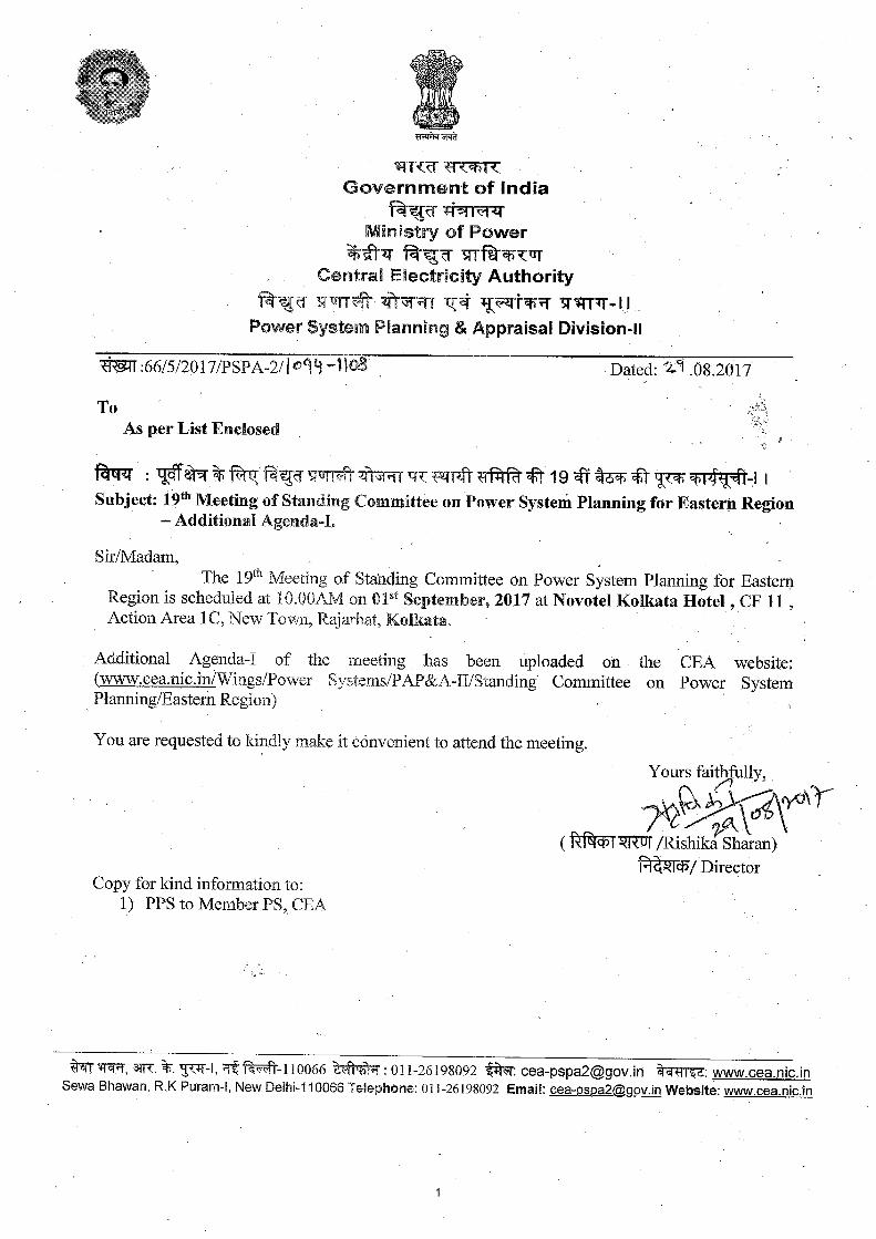
5.2.1 The three phase fault level at Farakka TPS (NTPC) at 400kV bus is found to be exceeding the designed short time current rating of equipment of 40kA. Presently, the fault level is about 46kA. Accordingly, system studies have been performed to propose measures to limit the fault current level by adopting various technical options like - bus splitting, switching arrangement,
7

AdditionalAgenda‐Ifor19thStandingCommitteeMeetingonPowerSystemPlanningofER
bypassing of lines, which were terminating at the specific substation or installation of series reactor or installation of fault current limiter etc. Moreover, the fault level of Farakka generation switchyard in 2021-22 time-frame is expected to be about 57.6kA. The expected power flow and fault current at Farakka bus is shown below:
Power Flow
8

AdditionalAgenda‐Ifor19thStandingCommitteeMeetingonPowerSystemPlanningofER
5.2.2 To limit the fault current level at Farakka, it is proposed to bypass Durgapur – Farakka (150km) 400kV D/c and Farakka – Kahalgaon (95km) 400kV 1st D/c (ckt-1 & 2) lines outside the switchyard so as to form Durgapur – Kahalgaon 400kV D/c line. With this arrangement fault level at Farakka reduces to 47kA from 57.5kA in the timeframe of 2021-22.
5.2.3 In order to further reduce the fault level, it was proposed to sectionalise the Farakka 400kV bus and install a 12 ohm series reactor between the two bus sections as per arrangement shown below. With this proposed rearrangement the fault level of the two bus sections viz. Farakka-A and Farakka-B comes down to 33.5kA and 37.5kA respectively. Study results
Fault Current
9
AdditionalAgenda‐Ifor19thStandingCommitteeMeetingonPowerSystemPlanningofER
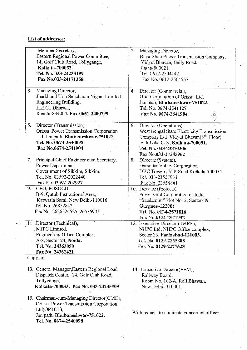
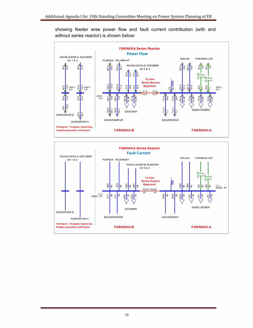
showing feeder wise power flow and fault current contribution (with and without series reactor) is shown below:
Power Flow
Fault Current
10
AdditionalAgenda‐Ifor19thStandingCommitteeMeetingonPowerSystemPlanningofER
5.3 From above study results, it may be observed that power flow on the transmission lines connected at either sections of Farakka bus is within acceptable limits.
5.4 Representative of NTPC informed that the Auxiliary power supply system for the entire Farakka generating station is derived from a common 33kV system which is fed from the generation voltage level through Two number tie transformers connected in Section-A and One number tie transformer connected in Section-B. Further, presently there is no provision of segregation of Auxiliary power supply system (at 33kV Level) between the units connected on Bus section-A (Units#1, 2, 3 and 4) and Bus section-B (Units#5 and 6)
Power Flow
Fault Current
11
AdditionalAgenda‐Ifor19thStandingCommitteeMeetingonPowerSystemPlanningofER
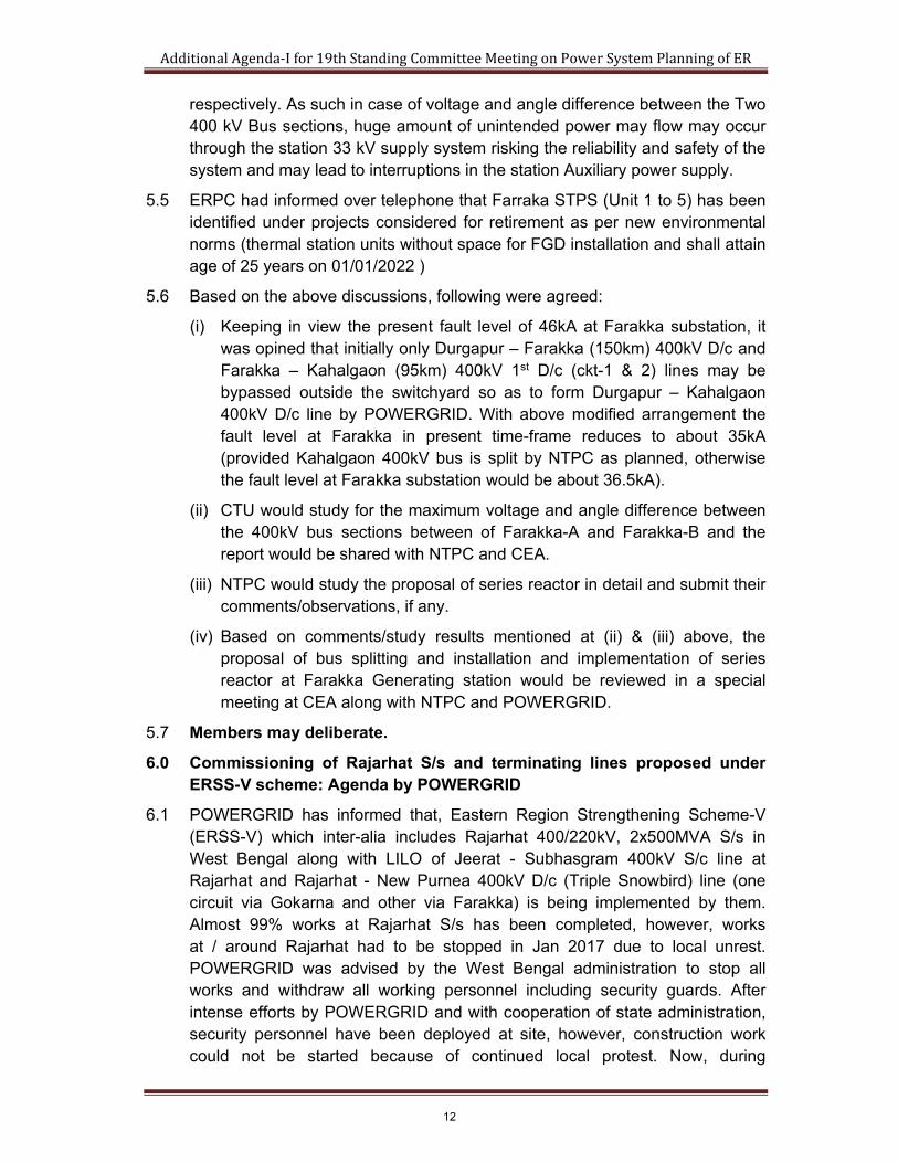
respectively. As such in case of voltage and angle difference between the Two 400 kV Bus sections, huge amount of unintended power may flow may occur through the station 33 kV supply system risking the reliability and safety of the system and may lead to interruptions in the station Auxiliary power supply.
5.5 ERPC had informed over telephone that Farraka STPS (Unit 1 to 5) has been identified under projects considered for retirement as per new environmental norms (thermal station units without space for FGD installation and shall attain age of 25 years on 01/01/2022 )
5.6 Based on the above discussions, following were agreed:
(i) Keeping in view the present fault level of 46kA at Farakka substation, it was opined that initially only Durgapur – Farakka (150km) 400kV D/c and Farakka – Kahalgaon (95km) 400kV 1st D/c (ckt-1 & 2) lines may be bypassed outside the switchyard so as to form Durgapur – Kahalgaon 400kV D/c line by POWERGRID. With above modified arrangement the fault level at Farakka in present time-frame reduces to about 35kA (provided Kahalgaon 400kV bus is split by NTPC as planned, otherwise the fault level at Farakka substation would be about 36.5kA).
(ii) CTU would study for the maximum voltage and angle difference between the 400kV bus sections between of Farakka-A and Farakka-B and the report would be shared with NTPC and CEA.
(iii) NTPC would study the proposal of series reactor in detail and submit their comments/observations, if any.
(iv) Based on comments/study results mentioned at (ii) & (iii) above, the proposal of bus splitting and installation and implementation of series reactor at Farakka Generating station would be reviewed in a special meeting at CEA along with NTPC and POWERGRID.
5.7 Members may deliberate.
6.0 Commissioning of Rajarhat S/s and terminating lines proposed under ERSS-V scheme: Agenda by POWERGRID
6.1 POWERGRID has informed that, Eastern Region Strengthening Scheme-V (ERSS-V) which inter-alia includes Rajarhat 400/220kV, 2x500MVA S/s in West Bengal along with LILO of Jeerat - Subhasgram 400kV S/c line at Rajarhat and Rajarhat - New Purnea 400kV D/c (Triple Snowbird) line (one circuit via Gokarna and other via Farakka) is being implemented by them. Almost 99% works at Rajarhat S/s has been completed, however, works at / around Rajarhat had to be stopped in Jan 2017 due to local unrest. POWERGRID was advised by the West Bengal administration to stop all works and withdraw all working personnel including security guards. After intense efforts by POWERGRID and with cooperation of state administration, security personnel have been deployed at site, however, construction work could not be started because of continued local protest. Now, during
12

AdditionalAgenda‐Ifor19thStandingCommitteeMeetingonPowerSystemPlanningofER
discussion with Govt. of West Bengal, it emerged that efforts for re-commencement of construction activities can be made only if general public is assured that no more transmission lines would be constructed at and around Rajarhat.
6.2 Further, it may be noted that LILO of Jeerat - Subhasgram 2nd 400kV line is proposed at Rajarhat under ERSS-XVIII, which is being implemented through TBCB route by M/S POWERGRID Medinipur Jeerat Transmission Ltd.
6.3 Members may deliberate.
7.0 Evacuation system for Talcher-III (2x660MW) project of NTPC
7.1 NTPC vide letter dated 30-01-2017 has indicated that they propose to establish a 2x660MW generating plant within the existing Talcher Thermal Power Station Complex in Odisha. Accordingly, they have requested for finalisation of evacuation voltage level and evacuation system for the Talcher-III generation project.
7.2 Accordingly, a meeting regarding evacuation system of Talcher-III project of NTPC and other issues of transmission system of Odisha was held on 18.08.2017 at CEA. In the meeting following were discussed:
7.3 Representative of CTU stated as following:
i. 50% power of the Talcher-III generation project has been allocated to Odisha, 35% to various ER beneficiaries (Bihar, West Bengal, Jharkhand and Sikkim) and 15% is unallocated.
Beneficiary Quantum Percentage
Odisha 622.05 50.00%
Bihar 139.31 11.20%
West Bengal 196 15.75%
Jharkhand 82.7 6.65%
Sikkim 17.4 1.40%
Unallocated 186.64 15.00%
1244.1 100%
ii. Talcher-III project is located at about 20km from Angul (ISTS substation) and 10km from Meramundali/Meramundali-B (OPTCL substations). Accordingly, load flow studies have been performed for evolving evacuation system for Talcher-III project considering following two alternatives:
(a) Talcher-III – Angul 400kV D/c (Triple Snowbird) line
(b) Talcher-III – Meramundali-B 400kV D/c (Triple Snowbird) line
iii. Major load centres of Odisha are located near Angul, Meramundali, Khuntuni, Pandiabil, Paradeep, Duburi, Mendhasal and Bhadrak areas. In the Base Case study results i.e. without Talcher-III generation project, the said load centres of Odisha mainly draws about 1225MW power from Angul and 225MW from Baripada ISTS substations.
13

AdditionalAgenda‐Ifor19thStandingCommitteeMeetingonPowerSystemPlanningofER
iv. Study results with two alternative systems has been discussed below:
A. Talcher-III – Angul 400kV D/c (Triple Snowbird) line : ISTS system
Three cases have been studied for this alternative.
Case-A1: Base case with Talcher-III – Angul 400kV interconnection In this situation, power flow on Angul – Meramundali 400kV D/c line is about 1500MW and that on Meramundali – Khuntuni 400kV D/c line is about 1300MW, which violates the N-1 criteria on these corridors. Moreover, Meramundali-B – Khuntuni line is lightly loaded. Further, the fault level at Meramundali and Angul is about 48kA and 64kA respectively, which is beyond the rated capacity of the respective bus.
Case-A2: Case-A1 along with by-passing of 400kV LILOs of Talcher –Meramundali and Meramundali – Bolangir at Angul
In this situation, power flow on Meramundali – Khuntuni 400kV D/c line is about 965MW and Meramundali-B – Khuntuni 400kV D/c line is about 145MW. There is highly uneven loading on these corridors. With disconnection of 400kV load centres of Odisha from Angul, power is supplied to load centres through Sundargarh – Rourkela – Talcher – Meramundali and Jamshedpur – Baripada – Dubri – Pandiabil – Medhasal corridors. However, the fault level at Meramundali reduces to about 26kA, which is within permissible limits.
Case-A3: Case-A2 along with LILO of Meramundali – Angul/Bolangir at Meramundali-B
In this situation, power flow and fault levels are within permissible limits. Moreover, power distribution on Meramundali – Khuntuni and Meramundali-B – Khuntuni lines is quite balanced.
B. Talcher-III – Meramundali-B 400kV D/c (Triple Snowbird) line : Intra-state system (by OPTCL)
Three cases have been studied for this alternative too.
Case-B1: Base case with Talcher-III – Meramundali-B 400kV interconnection
In this situation, power flow on Meramundali-B – Khuntuni 400kV D/c line is about 1210MW, which violates the N-1 crieteria on this corridor. Moreover, power distribution on Meramundali – Khuntuni and Meramundali-B – Khuntuni lines is uneven. Further, the fault level at Meramundali is about 47.5kA, which is beyond its rated capacity.
Case-B2: Case-B1 along with by-passing of 400kV LILOs of Talcher –Meramundali and Meramundali – Bolangir at Angul
In this situation, power flow on Meramundali-B – Khuntuni 400kV D/c line is about 1220MW, which violates the N-1 crieteria on this corridor. Power distribution on Meramundali – Khuntuni and Meramundali-B – Khuntuni lines is
14

AdditionalAgenda‐Ifor19thStandingCommitteeMeetingonPowerSystemPlanningofER
still uneven. However, the fault level at Meramundali is reduced to about 27kA, which is under permissible limits.
Case-B3: Case-B2 along with LILO of Meramundali – Angul/Bolangir at Meramundali-B
In this situation, power flow and fault levels are within permissible limits. Moreover, power distribution on Meramundali – Khuntuni and Meramundali-B – Khuntuni lines is quite balanced.
v. Study results are summarised below:
vi. From the above study results it may be inferred that, 400kV LILOs of Talcher –Meramundali and Meramundali – Bolangir at Angul needs to be by-passed to control the fault level at Meramundali S/s under normal operating condition even without Talcher-III. The necessary arrangements to effect this is already under implementation wherein provision has been kept to connect the LILO lines at Angul bus as and when required particularly in case of grid incidents like outage of lines, generations etc.
vii. After bypassing the LILOs under normal operating condition, Odisha would be devoid of ISTS power from Angul which was earlier feeding the load centres at Meramundali, Mendhasal and Duburi etc. Thus, in order to feed these load centres and new emerging load centres like Khuntuni, Narendrapur, Bhadrak and Paradeep, Talcher-III project may be connected to Meramundali-B. This would strengthen the Odisha grid, improve voltage
Angul‐
Meramundali
(L1)
Meramundali‐
Khuntuni
(L2)
Meramundali B‐
Khuntuni
(L3)
AngulMeram
undali
Meram
undali B
0 Base Case (without Talcher‐III)1225
(N‐1: 1000)
1235
(N‐1: 1000)125 142 58 46 8.1
‐ L1 and L2: N‐1 violation
‐ Meramundali: SC violations
‐ Unbalanced loading on L2 and L3
A
A1 Talcher‐III ‐ Angul1500
(875+625)
1300
(N‐1: 1050)120 155 63.8 48 11.7
‐ L1: Base Case & N‐1 violation
‐ L2: N‐1 violation
‐ Angul & Meramundali: SC violations
‐ Unbalanced loading on L2 and L3
A2 A1 + Angul LILO bypass
Tlch Ang Mera‐175
Tlch Mera‐300
Mera Boln‐240
965 145 171 44.4 25.4 10.8 ‐ Unbalanced loading on L2 and L3
A3 A2 + LILO of Mera‐Boln at Mera B
Tlch Mera‐335
Tlch Angl Mera‐190
Mera Mera B‐695
Mera B Boln‐230
610 550 169 44.4 27 26.5
‐ Sufficient to meet system
requirement
‐ Higher system losses compared to
Case‐B3
B
B1 Talcher‐III ‐Meramundali‐B640
(373+268)415
1210
(N‐1: 1105)150 59 47.5 17.8
‐ Unbalanced loading on L2 and L3
‐ L3: N‐1 violation
‐ Meramundali: SC violations
B2 B1 + Angul LILO bypass
Tlch Mera‐115
Tlch Angl Mera ‐ 65
Mera Boln‐280
2351220
(N‐1: 1115)151 38.6 27 16.9
‐ Unbalanced loading on L2 and L3
‐ L3: N‐1 violation
B3 B2 + LILO of Mera‐Boln at Mera B
Tlch Mera‐65
Tlch Angl Mera‐40
Mera Mera B‐340
Mera B Boln‐290
705 670 145 38.6 33 32.6
‐ Sufficient to meet system
requirement
‐ Lower system losses compared to
Case‐A3
Case
No.
Talcher‐III Study Results
Talcher‐III ‐ Angul 400kV D/c line
Talcher‐III ‐ Meramundali‐B 400kV D/c line
Case
Power Flow (in MW)Odisha
Loss
(in MW)
Fault Current (in kA)
Remarks
15

AdditionalAgenda‐Ifor19thStandingCommitteeMeetingonPowerSystemPlanningofER
profile in these areas and reduce losses in the Odisha system. Moreover, it is recommended to LILO Meramundali – Bolangir line at Meramundali-B so as to enable even loading of Meramundali – Khuntuni and Meramundali-B – Khuntuni lines. Therefore, it may be concluded that the Case-B3 is a preferable scenario. Additionally, in the Case-B3 Odisha grid losses are about 25MW less compared to a similar case viz. Case-A3.
viii. Thus, the final evacuation system for Talcher-III project is proposed as follows:
(i) Talcher-III – Meramundali-B 400kV D/c (Triple Snowbird) line
(ii) LILO of Meramundali – Angul/Bolangir 400kV line at Meramundali-B
(iii) By-passing of 400kV LILOs of Meramundali – Bolangir and Talcher – Meramundali at Angul (by operation of already under implementation switching arrangement for bypassing 400kV LILOs)
7.4 Representative of NTPC stated that 50% power of the Talcher-III generation project has been allocated to Odisha, 35% to various ER beneficiaries as per the Gadgil formula (Bihar, West Bengal, Jharkhand and Sikkim) and 15% is unallocated. Suppose Talcher-III is connected to Odisha STU then other states will have to pay STU charges in addition to ISTS charges. In case Talcher-III is connected to ISTS, Odisha has to pay the ISTS charges.
7.5 Representative of NTPC further requested to connect one 400kV circuit from Talcher-III to Meramundali and another to Meramundali-B so that reliability of Talcher-III evacuation improves (considering substation outage). During the meeting the proposal was studied and it was observed that power flow parameters are in limits.
7.6 In view of the above, following was decided in the meeting:
(a) By-passing of 400kV LILOs of Meramundali – Bolangir and Talcher – Meramundali lines at Angul by operation of already under implementation switching arrangement for bypassing these LILOs as and when the scheme is implemented so as to limit fault current at Meramundali.
(b) LILO of Meramundali – Angul/Bolangir 400kV line at Meramundali-B – by Odisha under intra-state scheme
(c) Talcher-III – Meramundali-B 400kV D/c (Triple Snowbird) line (one circuit terminated at Meramundali and other circuit terminated at Meramundali-B)
7.7 Representative of Odisha stated that implementation of Talcher-III has been deffered in a high level meeting of Odisha Government. Accordingly, it was decided that evacuation system for Talcher-III may be planned after finalization of its implementation schedule as the state of grid changes from time to time.
7.8 Members may deliberate.
16

AdditionalAgenda‐Ifor19thStandingCommitteeMeetingonPowerSystemPlanningofER
8.0 Approval for construction of 2 nos. 400/220kV substation at Bhadrak and Paradip by OPTCL with revised connectivity: Agenda by OPTCL
8.1 OPTCL informed that, in the 18th standing committee meeting held on 13th June’2016 at Kolkata, in principle approval were given for two nos. of 400/220kV Substations at Bhadrak & Paradip in 13th Plan period that is by 2021- 22. The connectivity plan needs to be revised.
8.2 The revised connectivity plan for 400/220kV Bhadrak and Paradip Sub-station is given below.
The 400kV Pandiabil – Baripada (Kuchei) to be made LILO at 400/220kV S/S at Bhadrak.
220kV Duburi - Bhadrak D/c line will be LILOed at Bhadrak.
A 400kV D/c line from 400/220kV S/s at New Duburi will be connected to 400/220kV S/s at Paradip
A 220kV D/c line will be from 400/220 kV Paradip to 220/132 kV Pratapsasan
8.3 The above proposed 400/220kV substations at Bhadrak and Paradip with 400kV and 220kV connectivity may be approved for implementation under intra-state scheme by OPTCL.
8.4 OPTCL may update on the transformation capacity being planned at these substations.
8.5 PART-B: the future plan (for information only)
8.5.1 A 400/220kV sub-station at Dhamara with separate 400kV D/c lines from 400/220kV sub-stations at Bhadrak and Paradip.
8.5.2 The 400/220kV sub-station at Paradip to be connected with 400/220kV sub-station at Pandiabil.
8.5.3 OPTCL may update on the transformation capacity being planned at Dhamara substation.
8.6 Members may deliberate.
9.0 Approval for connectivity of 400/220kV sub-station at Narendrapur to 400/220kV Jaynagar (PG) with a 400kV D/c line in place of 400kV Angul-Narendrapur – Gazuwaka D/c line: Agenda by OPTCL
9.1 OPTCL informed that, in-principle approval was given for construction of 400/220 kV S/S at Narendrapur (intra-state) in the 18th CEA standing committee meeting held on 13th June’ 2016 at Kolkata. The connectivity planned in the standing committee may please be revised and approved as follows:
400kV D/c line Pandiabil (PG) to Narendrapur.
17
AdditionalAgenda‐Ifor19thStandingCommitteeMeetingonPowerSystemPlanningofER
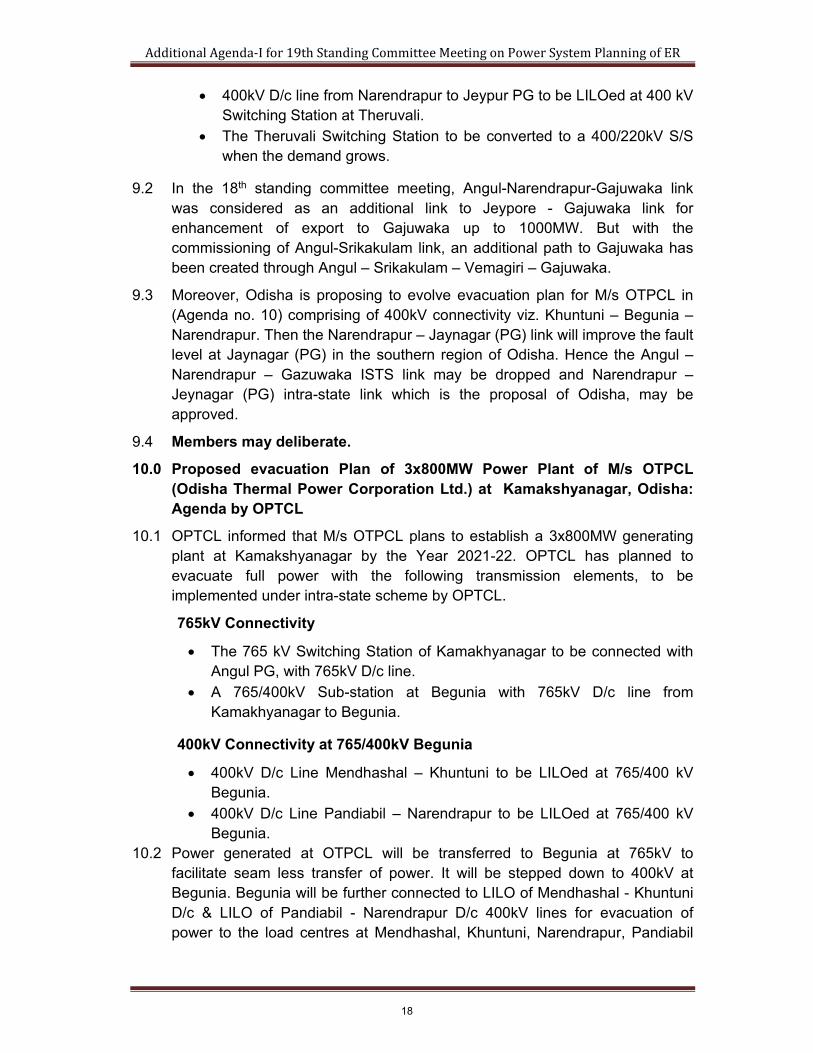
400kV D/c line from Narendrapur to Jeypur PG to be LILOed at 400 kV Switching Station at Theruvali.
The Theruvali Switching Station to be converted to a 400/220kV S/S when the demand grows.
9.2 In the 18th standing committee meeting, Angul-Narendrapur-Gajuwaka link was considered as an additional link to Jeypore - Gajuwaka link for enhancement of export to Gajuwaka up to 1000MW. But with the commissioning of Angul-Srikakulam link, an additional path to Gajuwaka has been created through Angul – Srikakulam – Vemagiri – Gajuwaka.
9.3 Moreover, Odisha is proposing to evolve evacuation plan for M/s OTPCL in (Agenda no. 10) comprising of 400kV connectivity viz. Khuntuni – Begunia – Narendrapur. Then the Narendrapur – Jaynagar (PG) link will improve the fault level at Jaynagar (PG) in the southern region of Odisha. Hence the Angul – Narendrapur – Gazuwaka ISTS link may be dropped and Narendrapur –Jeynagar (PG) intra-state link which is the proposal of Odisha, may be approved.
9.4 Members may deliberate.
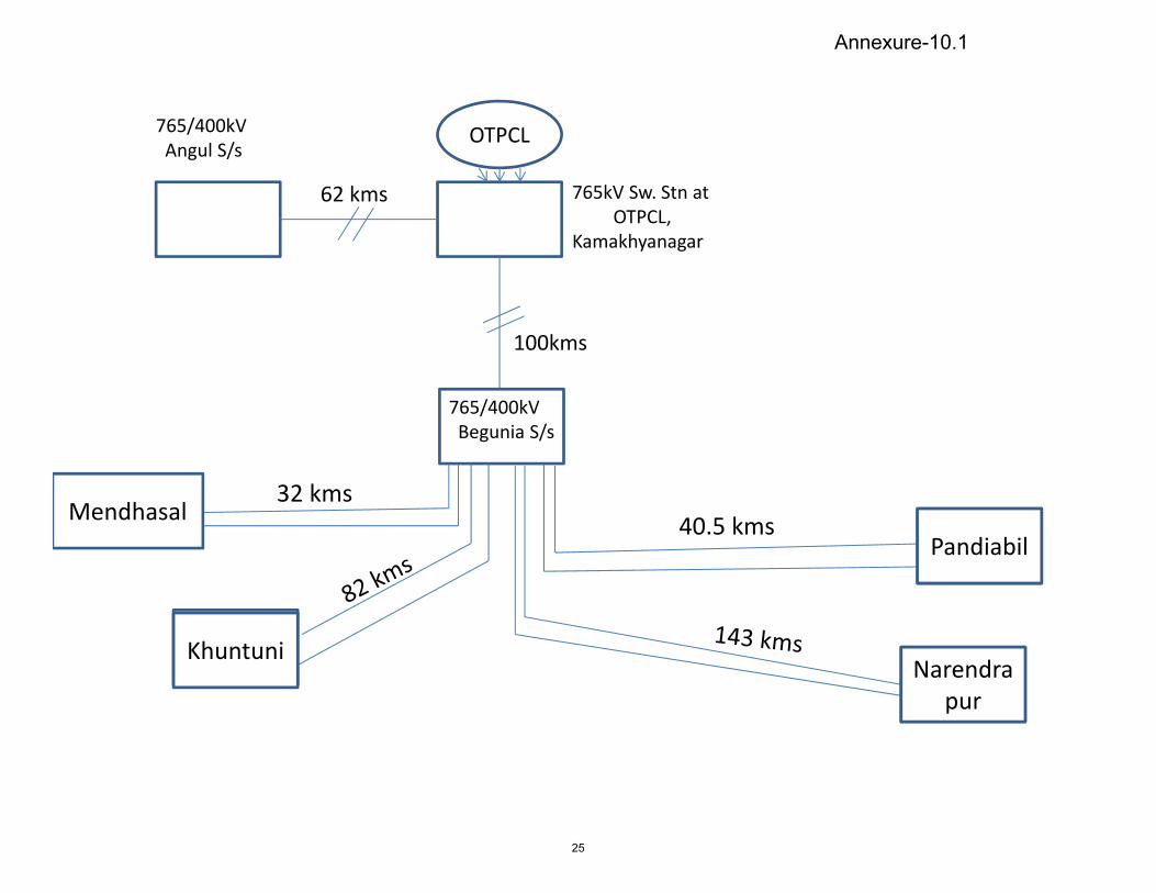
10.0 Proposed evacuation Plan of 3x800MW Power Plant of M/s OTPCL (Odisha Thermal Power Corporation Ltd.) at Kamakshyanagar, Odisha: Agenda by OPTCL
10.1 OPTCL informed that M/s OTPCL plans to establish a 3x800MW generating plant at Kamakshyanagar by the Year 2021-22. OPTCL has planned to evacuate full power with the following transmission elements, to be implemented under intra-state scheme by OPTCL.
765kV Connectivity
The 765 kV Switching Station of Kamakhyanagar to be connected with Angul PG, with 765kV D/c line.
A 765/400kV Sub-station at Begunia with 765kV D/c line from Kamakhyanagar to Begunia.
400kV Connectivity at 765/400kV Begunia
400kV D/c Line Mendhashal – Khuntuni to be LILOed at 765/400 kV Begunia.
400kV D/c Line Pandiabil – Narendrapur to be LILOed at 765/400 kV Begunia.
10.2 Power generated at OTPCL will be transferred to Begunia at 765kV to facilitate seam less transfer of power. It will be stepped down to 400kV at Begunia. Begunia will be further connected to LILO of Mendhashal - Khuntuni D/c & LILO of Pandiabil - Narendrapur D/c 400kV lines for evacuation of power to the load centres at Mendhashal, Khuntuni, Narendrapur, Pandiabil
18

AdditionalAgenda‐Ifor19thStandingCommitteeMeetingonPowerSystemPlanningofER
and Duburi. The connectivity with Angul will add stability to the evacuation plan. Hence two line bays at 765kV may be allotted at Angul to OPTCL.
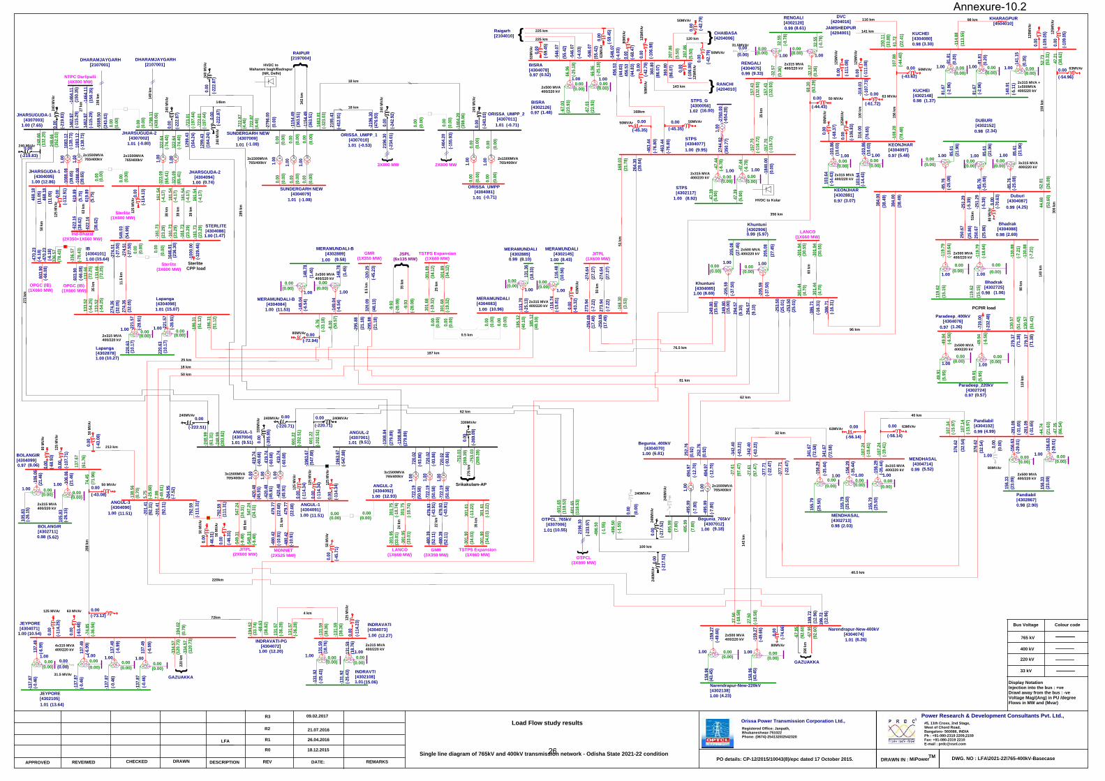
10.3 The detail single line diagram of the Proposed Plan with distance of Transmission line is at Annexure-10.1, Single line diagram of 765kV and 400kV transmission network with load flows of Odisha State for 2021-22 is at is at Annexure-10.2.
10.4 Odisha may indicate, if the entire power is to be consumed by the state. If Odisha desires to transfers power outside the state, then M/s OTPCL would need to apply for LTA for transfer of surplus power through ISTS.
10.5 In the meeting regarding evacuation system of Talcher-III project of NTPC and other issues of transmission system of Odisha held on 18.08.2017 at CEA the items mentioned at Agenda no. 7 to 10 were discussed among CEA, POWERGRID (CTU), POSOCO, OPTCL and GRIDCO. Thus, system studies were performed after the meeting as per the deliberation in the meeting and Odisha’s various proposals. The study results (load flow, observations and fault current) are at Annexure 10.3.
10.6 Members may deliberate.
11.0 Evacuation of power from 2x660MW project of OPGC: Agenda by OPTCL
11.1 OPTCL informed that the 2x660MW generating plant of OPGC is in advance stage of commissioning. The evacuation plan envisaged was as follows:
11.1.1 Out of 2 units of OPGC, one unit was meant for STU and the second was for ISTS. Accordingly, bus split was planned at OPGC. One 400kV D/c line was planned to be connected to Lapanga from state allocated unit and another unit was proposed to be connected to Sundargarh (Jharsuguda) through 400kV D/c (triple snowbird) ISTS line. The ISTS line is already under implementation through TBCB and is in advanced stages of commissioning.
11.2 In the changed scenario, OPTCL is planning for evacuation of full quantum of power from OPGC as it is envisaged that entire power of OPGC may be allocated to Odisha. The matter was discussed at a meeting held at CEA on 18-08-2017. Therein, Odisha mentioned that since Odisha is going to avail the entire power, the OPGC – Jharsuguda 400kV D/c (Triple Snowbird) ISTS line may be transferred from M/s Odisha Generation Phase-II Transmission Limited to M/s OPTCL. Thus, it will be a STU line and Odisha would not have to bear ISTS charges for drawl of its share of power. It was decided that the matter may be taken up for discussion in the SCM.
11.3 Members may deliberate.
12.0 Connectivity of Railways TSS with ISTS Network for Ludhiana-Delhi-Sonnagar routes
12.1 Indian Railways is planning to connect its TSSs between Ludhiana-Delhi-Sonnagar routes of Railways by way of construction of associated
19

AdditionalAgenda‐Ifor19thStandingCommitteeMeetingonPowerSystemPlanningofER
infrastructure including transmission lines and bay extension work at ISTS points preferably at 220 kV.
12.2 Railway Board vide its letter no. 2012/Elect (G) /150/1 Pt – II dated 28.12.2016 has requested for connectivity to railways from various ISTS points. Power requirement of Railways from the nearby proposed ISTS points is as follows:
CONNECTIVITY SCHEME OF TSS ALONG LUDHIANA - DELHI- SONNAGAR ROUTE
Sl.No
PGCIL GSS Connectivity
required at (kV) Railway TSS to
be supplied Grid Voltage at
TSS (kV) Tentative load
requirment (MW)
1
Abdullapur 220
Jagadhari-I 220
50 2 Jagadhari-II 220 3 Tapri 132 4 Muzaffarnagar 132 5
Meerut 220
Jarauda Nara 132
50 6 Hapur 132 7 Gulaothi 132 8 Wair 132 9
* Pasauli (Sasaram)
220
Durgaoti 132
75
10 Deoria 132 11 Chandiapur 132 12 Gadhion 132 13 Jeonathpur 132 14 Chunar 132 12.3 M/s POWERGRID is requested to furnish the information regarding the
availability of space for 220kV bays and margins in transformation capacity at Pasauli (Sasaram).
12.4 A meeting regarding Connectivity of Railways TSS with ISTS Network at Abdullapur, Meerut and Sasaram for Ludhiana-Delhi-Sonnagar route was held in CEA on 21.07.2017 (Copy of MoM enclosed as Annexure 12.1). The following were decided in the meeting.
(i) As no representative from Bihar was present in the meeting no decision could be taken in respect of connectivity to Railways TSS at Sasaram substation.
(ii) Railways would utilize existing two number of 220 kV bays at Abdullapur substation (presently used for 220 kV supply to Jagadhari TSS) to meet their additional traction load requirement. The required technical upgradation of the 220 kV line (presently only two phases has been strung) would be carried out by Railways subject to fulfilment of all the existing agreements of HVPNL with Railways for this line.
(iii) Two nos. of 220 kV (GIS) bays at Meerut 400/200kV substation along with establishment of 220/132kV, 2x100 MVA GIS in the premises of Meerut 400/220 kV substation was agreed for providing connectivity to Railways. The cost of above works shall be borne by Railways. Railways to implement 132 kV D/c interconnection from Meerut (PG) to their 132 kV substation.
20

AdditionalAgenda‐Ifor19thStandingCommitteeMeetingonPowerSystemPlanningofER
12.5 Members may deliberate.
13.0 Additional outlets from Darlipalli STPP and North Karanpura STPP for mining activities ( Agenda by NTPC)
13.1 NTPC informed that the Associated Transmission System of Darlipali STPP stage-I (2x800MW) project was finalized in 13th ER Standing Committee Meeting and LTOA meeting held on 12th February 2012 with the following Evacuation system:
Darlipali – Jharsuguda (Sundergarh Pool) 765kV D/c line
13.2 Coal for the project is planned to be sourced from Dulanga captive coal mine allocated to NTPC by GoI which is located at a distance of 10km from the project.
13.3 NTPC had approached OPTCL for power supply to Dulanga mine as HT consumer however it has been asked by GRIDCO to draw the power for this mine from GRIDCO share of power in Darlipali directly from the generation switchyard in view of vicinity to the generation project. As such suitable arrangement has been made in the auxiliary power supply system of the project for providing 15 MVA power to the linked mine at 33kV voltage level.
13.4 Further, GRIDCO has also allotted additional 15MVA of power for Manoharpur coal mine of OCPL(in vicinity of Dulanga mines) and has asked them to draw power directly from DSTPP generation switchyard as being done in case of Dulanga mines.
13.5 It may be noted that these load centres are radially fed from the generation switchyard.
13.6 Further, for meeting the power supply requirement of captive Chati Bariatu & Kerandari and Pakri Barwadih coal mines, 2 nos. 220kV feeder from North Karanpura project has been planned. Power from NKSTPP to mines also shall be drawn in radial mode.
13.7 Power supply scheme indicated the above arrangements is at Annexure-13.1
13.8 In view of the above it is requested that above drawls may be considered as drawl by GRIDCO/ Jharkhand from their share of allocated power from Darlipalli and North Karanpura projects. Also required interface energy meters shall be installed by CTU.
13.9 Members may deliberate.
14.0 Interim arrangement for power evacuation from Nabinagar TPP (3X660MW)
14.1 The 1st unit of Nabinagar TPP (3x660MW) is in advance stage of completion and anticipated to be synchronized in Oct' 17. The scheduled commissioning of this unit is in Nov' 17. The evacuation system for Nabinagar TPP includes Nabinagar - Gaya 400kV D/C (Quad) transmission line awarded by
21
AdditionalAgenda‐Ifor19thStandingCommitteeMeetingonPowerSystemPlanningofER
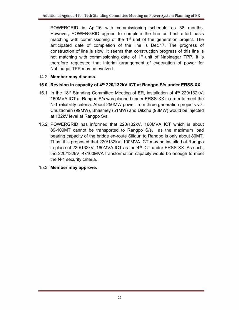
POWERGRID in Apr'16 with commissioning schedule as 38 months. However, POWERGRID agreed to complete the line on best effort basis matching with commissioning of the 1st unit of the generation project. The anticipated date of completion of the line is Dec'17. The progress of construction of line is slow. It seems that construction progress of this line is not matching with commissioning date of 1st unit of Nabinagar TPP. It is therefore requested that interim arrangement of evacuation of power for Nabinagar TPP may be evolved.
14.2 Member may discuss.
15.0 Revision in capacity of 4th 220/132kV ICT at Rangpo S/s under ERSS-XX
15.1 In the 18th Standing Committee Meeting of ER, installation of 4th 220/132kV, 160MVA ICT at Rangpo S/s was planned under ERSS-XX in order to meet the N-1 reliability criteria. About 250MW power from three generation projects viz. Chuzachen (99MW), Bhasmey (51MW) and Dikchu (98MW) would be injected at 132kV level at Rangpo S/s.
15.2 POWERGRID has informed that 220/132kV, 160MVA ICT which is about 89-109MT cannot be transported to Rangpo S/s, as the maximum load bearing capacity of the bridge en-route Siliguri to Rangpo is only about 80MT. Thus, it is proposed that 220/132kV, 100MVA ICT may be installed at Rangpo in place of 220/132kV, 160MVA ICT as the 4th ICT under ERSS-XX. As such, the 220/132kV, 4x100MVA transformation capacity would be enough to meet the N-1 security criteria.
15.3 Member may approve.
22

Annexure-1.1
23
24
765/400kV Angul S/s
62 kms 765kV Sw. Stn at OTPCL,
Kamakhyanagar
OTPCL
765/400kV Begunia S/s
Mendhasal
100kms
Khuntuni
Pandiabil
Narendrapur
32 kms40.5 kms
Annexure-10.1
25
(10.54)1.00
JEYPORE[4304071]
(12.20)1.00
INDRAVATI-PG[4304072]
BOLANGIR[4304099]
(12.27)1.00
INDRAVATI[4304073]
(15.07)1.01
Lapanga[4304098]
(7.65)1.00
JHARSUGUDA-1[4307003]
(0.52)0.97
BISRA[4304078]
(9.33)0.99
RENGALI[4304075]
(9.51)
(9.95)
ANGUL-2[4307001]
1.00
1.01
STPS[4304077]
(12.86)1.00
JHARSGUDA-1[4304095]
(5.48)0.97
KEONJHAR[4304097]
(3.30)0.98
KUCHEI[4304080]
(5.52)0.99
MENDHASAL[4304714]
(4.99)0.99
Pandiabil[4304102]
(13.64)1.01
MONNET(2X525 MW)
JEYPORE[4302105]
GAZUAKKA(15.06)1.01
INDRAVTI[4302108]
MERAMUNDALI[4304083]
(10.27)1.00
Lapanga[4302878]
(15.64)1.00
IB[4304101]
Ind-Bharat(2X350+1X660 MW)
DHARAMJAYGARH[2107001]
(1.48)0.97
BISRA[4302126]
RANCHI[4204010]
(8.92)1.00
STPS[4302117]
(8.61)0.99
RENGALI[4302120]
(3.07)0.97
KEONJHAR[4302881]
(1.37)0.98
KUCHEI[4302148]
(2.34)0.98
DUBURI[4302152]
(2.90)0.98
Pandiabil[4302867]
(8.43)1.00
MERAMUNDALI [4302145]
BOLANGIR[4302711]
1083
.12
(-138
.73)
-108
8.08
(39.
65)
-133
.66
(-4.1
7)16
1.54
(72.
25)
133.
52(-5
4.25
)
194.
02(0
.79)
-194
.52
(33.
74)
(120
.73)
131.
57(-3
6.28
)
-131
.59
(38.
36)
-184
0.00
(0.0
0)
(4.25)0.99
Duburi[4304087]
KHARAGPUR[4504010]
(113
.55)
TM
Registered Office: Janpath,Bhubaneshwar-751022Phone: (0674)-2541320/2542320
Orissa Power Transmission Corporation Ltd.,
MiPowerAPPROVED CHECKED
18.12.2015R0
REV DRAWN IN :
400 kV
765 kV
REMARKS
(2.03)0.98
MENDHASAL[4302713]
ANGUL-1[4304091]
OPGC (IB)(1X660 MW)
1.00 (11.51)
(-66.
08)
603.
90
149
km
38 k
m
35 k
m
276
km
72km4 km
141 km
22 k
m
116 km 98 km
356 km
85 k
m
143 km
1.00 (0.74)
-161
.73
(23.
29)
(-4.1
7)-1
61.7
3(2
3.29
)16
1.54
1646
.91
(236
.30)
11.5
km
REVEIWED
(-0.80)1.01
JHARSUGUDA-2[4307002]
(1.47)1.00
220 kV
468.
18(1
1.05
)-4
70.2
3(-6
.18)
(12.93)1.00
ANGUL-2[4304092]
720.
02(-9
3.86
)-7
22.1
9(5
0.58
)
1.00
{
{
156
km
Sterlite(1X600 MW)
DRAWN DESCRIPTION DATE:
-334
.57
-114
.88CHAIBASA
[4204006]
STERLITE[4304086]
161.
54(-4
.17)
-161
.73
(23.
29)
161.
54(-4
.17)
-161
.73
(23.
29)
1.00
66.9
6(-2
5.18
)
-67.
03(2
3.93
)
0.00(0.00)
66.9
6(-2
5.18
)
-67.
03(2
3.93
)
0.00(0.00)
1.00
50MVAr
330M
VAr
-133
.66
(72.
25)
133.
52(-5
4.25
)
(-28.
91)
0.00(0.00)
1.00-221
.57
(-28.
91)
220.
63(1
0.17
)
0.00(0.00)
1.002x315 MVA400/220 kV
JITPL(2X600 MW)
137.
49(-6
.99)
-137
.87
(-0.4
6)
0.00(0.00)
1.00
137.
49(-6
.99)
-137
.87
(-0.4
6)
0.00(0.00)
1.00
-334
.57
(120
.73)
131.
57(-3
6.28
)
-131
.59
(38.
36)
131.
59(1
8.76
)
-131
.92
(-25.
43)
0.00(0.00)
1.00131.
59(1
8.76
)
-131
.92
(-25.
43)
0.00(0.00)
1.00
31.5 MVAr
125
MVA
r
-156
.63
(-29.
01)
156.
33(2
3.09
)
0.00(0.00)
1.00-156
.63
(-29.
01)
156.
33(2
3.09
)
0.00(0.00)
1.00
2x500 MVA400/220 kV
-156
.29
(-35.
44)
155.
79(2
5.50
)
0.00(0.00)
1.00-156
.29
(-35.
44)
155.
79(2
5.50
)
0.00(0.00)
1.00
3x315 MVA400/220 kV
468.
18(1
1.05
)-4
70.2
3(-6
.18)
-85.
76(-2
5.08
)85
.61
(21.
96)
0.00(0.00)
1.00
-85.
76(-2
5.08
)85
.61
(21.
96)
0.00(0.00)
1.003x315 MVA400/220 kV
2x315 MVA +1x500MVA400/220 kV
-81.
81(0
.20)
81.6
7(-2
.96)
0.00(0.00)
1.00
-81.
81(0
.20)
0.00(0.00)
1.00
-103
.86
(10.
03)
103.
64(-1
4.43
)
0.00(0.00)
1.00-103
.86
(10.
03)
103.
64(-1
4.43
)
0.00(0.00)
1.00
2x315 MVA400/220 kV
-32.
57(0
.36)
32.5
5(-0
.78)
0.00(0.00) 1.00
-32.
57(0
.36)
32.5
5(-0
.78)
0.00(0.00) 1.00
31.5MVAr
(16.00)1.02
STPS_G[4300056]
2744
.82
(350
.77)
-276
0.00
(-654
.28)
1.00
-116
.74
(-15.
81)
0.00(0.00)
1.00
-47.
44(-6
.78)
47.3
9(5
.90)
0.00(0.00)
1.00-47.
44(-6
.78)
47.3
9(5
.90)
0.00(0.00)
1.00
720.
02(-9
3.86
)-7
22.1
9(5
0.58
)
1.00
24 k
m
HVDC to Kolar
0.00
(-114
.25)
4x315 MVA400/220 kV
0.00(0.00)
50 MVAr
0.00(0.00)
125 MVAr
0.00
(-106
.98)
50MVAr
2x315 MVA400/220 kV
Srikakulam-AP
0.00
(-42.
79)
0.00
125M
VAr
0.00
(-45.35)
0.00(-45.35)
2x315 MVA400/220 kV
50MVAr
0.00
(-61.72)
2x1500MVA765/400kV
0.00
(-45.
71)
2x315 MVA400/220 kV
0.00
(-44.43)
3x1500MVA765/400kV3x1500MVA
765/400kV
240
MVA
r
2x315 MVA400/220 kV
2x1500MVA765/400kV
2x315 MVA400/220 kV
2x500 MVA400/220 kV
35 k
m
(8.10)0.99
MERAMUNDALI [4302885]
116.
48(1
0.56
)
-131
.70
(-25.
13)
131.
36(1
8.33
)
0.00(0.00)
1.00
}Bus Voltage Colour code
63M
VAr
120 km
220.
63(1
0.17
)
Three phase to ground fault in MVA.
(65.
41)
322.
64(-7
4.40
)
322.
64
-323
.09
1.00
(-74.
40)
(65.
41)
-323
.09
1.00
JHARSGUDA-2[4304094]
1083
.12
(-138
.73)
-108
8.08
(39.
65)
285
km
274.
36(3
2.05
)-2
74.5
1(-2
7.50
)
(9.51)1.01
ANGUL-1[4307004]
419.
74-4
20.4
8(-6
0.68
)(4
5.91
)
1.00
-420
.48
419.
74(-6
0.68
)(4
5.91
)
1.00
419.
74(-6
0.68
)-4
20.4
8(4
5.91
)
1.00
31 k
m
(52.
11)
479.
93-4
80.3
9
479.
93-4
80.3
9(5
2.11
)(-4
3.91
)
(-43.
91)
38 k
m
38 k
m
Raigarh[2104010]
DVC[4204016]
JAMSHEDPUR[4204001]
107.
14(-1
5.97
)
-107
.24
(-19.
41)
107.
14(-1
5.97
)
-107
.24
(-19.
41)
LANCO(1X660 MW)
GMR(1X350 MW)
-248
.99
(61.
31)
248.
66(1
32.2
0)
-248
.99
(283
.82)
248.
66(3
52.0
3)
272
km
(8.06)0.97
(5.7
5)
(38.
62)
33 kV
#5, 11th Cross, 2nd Stage,West of Chord Road,Bangalore- 560086, INDIAPh : +91-080-2319 2209,2159Fax: +91-080-2319 2210E-mail : [email protected]
Power Research & Development Consultants Pvt. Ltd.,
-156
.29
(-35.
44)
155.
79(2
5.50
)
0.00(0.00)
1.00
47.2
1(3
8.62
)30
0 km
50 k
m
63 k
m
619.
89
(5.7
5)61
9.89
-622
.16
(38.
62)
336.
57(7
8.43
)
-336
.57
(-78.
43)
-622
.16
OPGC (IB)(1X660 MW)
(-66.
08)
603.
90
SterliteCPP load
0.00
(0.0
0)
0.00
(0.0
0)-2
21.5
7
549.
03(5
4.99
)
(243
.63)
0.00
(-219
.83)
63 MVAr
0.00
(-222
.87)
125
MVA
r
0.00(-219.83)
240
MVA
r
1.00
1.00
0.00
(-112
.91)
240 MVAr
0.00
(-114
.13)
125
MVA
r
301.
75(-1
8.74
)-3
01.9
5(3
3.01
)30
1.75
(-18.
74)
-301
.95
(33.
01)
0.00
(-42.
79)
0.00
(-68.
47)
125M
VAr
50MVAr
50M
VAr
225 km
0.00
(-106
.98)
0.00
(-59.
45)
63MVAr
63M
VAr
(-42.
79)
0.00
(-111
.08)
0.00 (-111
.08)
125M
VAr
125M
VAr
0.00
(-68.
37)
0.00
(-106
.83)
80M
VAr
125M
VAr
547.
24(2
4.31
)-5
49.3
1(-9
.49)
547.
24(2
4.31
)-5
49.3
1(-9
.49)
479.
77(2
2.68
)-4
80.4
2(-1
0.91
)47
9.77
(22.
68)
-480
.42
(-10.
91)
0.00(0.00)
0.00(0.00)
0.00
(-114
.34)
0.00
(-114
.34)
0.00
(-114
.34)
125
MVA
r
125
MVA
r
50 M
VAr
0.00
(-46.
31)
0.00
(-46.
31)
50 M
VAr
50 M
VAr
-106
.06
(21.
46)
105.
83(-2
6.15
)
0.00(0.00)
1.00
-106
.06
(21.
46)
105.
83(-2
6.15
)
0.00(0.00)
1.00
(5.62)0.98
0.00
(-68.
93)
0.00 (-107
.71)
125
MVA
r
125
MVA
r
0.00
(-43.
08)
50 MVAr0.00(-43.08)
80 M
VAr
63 MVAr
0.00
(-114
.23)
50 M
VAr
52.7
3(5
3.31
)-5
2.81
(26.
09)
150
km14
0 km
0.00
(-109
.05)
0.00
(-109
.05)
125M
VAr
125M
VAr
0.00
(-43.62)
63MVAr
0.00(-54.96)
50MVAr
63M
VAr
0.00
(-56.14)
0.00
(-56.14)
80M
VAr
63MVAr
330MVAr
-753
.03
(269
.39)
-753
.03
(269
.39)
}
JSPL(6x135 MW)
225 km
0.00
(-269
.09)
0.00
(-59.
45)
-141
.15
(0.3
5)
140.
91(-5
.11)
0.00(0.00)
1.00
81.6
7(-2
.96)
(11.51)1.00
ANGUL-3[4304090]
(11.53)1.00
MERAMUNDALI-B[4304084]
(9.58)1.00
MERAMUNDALI-B[4302889]
-149
.04
(-6.5
4)14
8.78
(1.4
5)
0.00(0.00)
1.00
-149
.04
(-6.5
4)14
8.78
(1.4
5)
0.00(0.00)
1.00
2x500 MVA400/220 kV
137.
67(6
1.76
)
-138
.56
(0.7
0)
8.5
km
0.00
(0.0
0)
0.00
(0.0
0)
0.5 km
-320
.25
(-45.
23)
320.
09(4
8.13
)
0.00
(0.0
0)
(0.0
0)0.
00
-792
.59
(111
.31)
792.
59(-1
11.3
1)
213 km
185.
12(4
0.10
)
-186
.31
(51.
12)
185.
12(4
0.10
)
-186
.31
(51.
12)
187 km
0.00
(0.0
0)
0.00 (0.0
0)
Display NotationInjection into the bus : +veDrawl away from the bus : -veVoltage Mag/(Ang) in PU /degreeFlows in MW and (Mvar)
DWG. NO : LFA\2021-22\765-400kV-Basecase
Load Flow study results
LFA
-85.
76(-2
5.08
)85
.61
(21.
96)
0.00(0.00)
1.00
27 k
mNTPC Darlipalli
(4X800 MW)
(8.69)1.00
Khuntuni[4304085]
(5.97)0.99
Khuntuni[4302906]
-205
.59
(-37.
50)
205.
08(2
7.45
)
0.00(0.00)
1.00
-205
.59
(-37.
50)
205.
08(2
7.45
)
0.00(0.00)
1.00
2x500 MVA400/220 kV
81 km
294.
57(9
.10)
-295
.88
(21.
18)
294.
57(9
.10)
-295
.88
(21.
18)
76.5 km
384.
00(3
8.49
)
-386
.71
(-16.
31)
384.
00(3
8.49
)
-386
.71
(-16.
31)
96 km
-47.
35(6
6.54
)
(6.26)1.01
Narendrapur-New-400kV[4304074]
(4.23)1.00
Narendrapur-New-220kV[4302138]
-159
.27
(-49.
66)
158.
96(4
3.45
)
0.00(0.00)
1.00
-159
.27
(-49.
66)
158.
96(4
3.45
)
0.00(0.00)
1.00
40 km
2x500 MVA400/220 kV
PO details: CP-12/2015/10043(8)/epc dated 17 October 2015.
-179
8.11
(438
.06)
61.7
2(2
2.41
)
150.
11(3
3.88
)
360.
80(8
6.07
)
360.
80(8
6.07
)
207.
86(5
.50)
207.
86(5
.50)
-546
.07
(-4.0
3)
-546
.07
(55.
42)
-546
.07
(55.
42)
-546
.07
(-4.0
3)
(1.26)0.97
Paradeep_400kV[4304076]
GMR(3X350 MW)
-720
.00
(-232
.48)
PCPIR load
-108
.28
(78.
48)
107.
88(-4
4.40
)
316.
00(7
6.65
)-3
18.0
3(-1
07.7
3)
157.
43(1
32.9
3)-1
57.7
0(-1
16.7
2)
157.
43(1
32.9
3)-1
57.7
0(-1
16.7
2)
35 k
m
456.
53(4
4.83
)
-463
.44
(-76.
80)
456.
53(4
4.83
)
-463
.44
(-76.
80)
168km
1299
.43
(164
.24)
-130
8.84
(279
.89)
1299
.43
(164
.24)
-130
8.84
(279
.89)
{
{
(-1.08)1.01
SUNDERGARH NEW[4307009]
(-1.08)1.01
SUNDERGARH NEW[4304079]
0.00
(0.0
0)0.
00(0
.00)
1.00
0.00
(0.0
0)0.
00(0
.00)
1.00
0.00
(0.0
0)0.
00(0
.00)
1.00
3x1500MVA765/400kV
(-0.53)1.01
ORISSA_UMPP_1[4307010]
2196
.30
(-234
.01)
{
3X800 MW
0.00
(-242
.92)
240
MVA
r
-219
6.30
(476
.93)
2195
.43
(-412
.91)
18 km
(-0.71)1.01
ORISSA_UMPP_2[4307011]
1464
.20
(-155
.93)
{
2X800 MW
0.00
(-243
.03)
240
MVA
r
0.00
(0.0
0)
0.00
(0.0
0)
14km
-115
4.49
(363
.51)
-115
4.49
(363
.51)
343
km
{RAIPUR[2197004]
-279
6.00
(0.0
0)
HVDC toMaharani bagh/Badrapur
(NR, Delhi)
(-0.71)1.01
ORISSA_UMPP[4304081]
0.00
(0.0
0)0.
00(0
.00)
1.00
0.00
(0.0
0)0.
00(0
.00)
1.00
JITPL(1X600 MW)
50 k
m
-723
.01
(-197
.44)
722.
87(4
.46)
-723
.01
(-197
.44)
722.
87(4
.46)
1463
.81
(-323
.03)
-146
4.20
(398
.96)
18 km
0.00
(0.0
0)
0.00
(0.0
0)
(2.69)0.98
Bhadrak[4304088]
(1.06)0.98
Bhadrak[4302725]
-119
.79
(-18.
64)
119.
62(1
5.15
)
0.00(0.00)
1.00
-119
.79
(-18.
64)
119.
62(1
5.15
)
0.00(0.00)1.00
2x500 MVA400/220 kV
-251
.29
(-5.3
9)25
0.67
(25.
86)
-251
.29
(-5.3
9)25
0.67
(25.
86)
51km
100
km
156
km
168.
03(2
1.78
)-1
68.3
0(3
.53)
51 k
m
-274
.64
(27.
27)
273.
94(-7
.22)
-274
.64
(27.
27)
273.
94(-7
.22)
-9.9
3(-2
8.08
)
-9.9
3(-2
8.08
)
80 M
VAr
-274
.51
(-27.
50)
274.
36(3
2.05
)
0.00
(-74.
66)
GAZUAKKA
0.00
(-70.
63)
0.00
(-222
.87)
0.00
(-222
.87)
240
MVA
r
240
MVA
r
DHARAMJAYGARH[2107001]
0.00(-43.62)
-301
.94
(30.
55)
301.
44(4
.70)
-301
.94
(30.
55)
301.
44(4
.70)
60 k
m
LANCO(1X660 MW)
-301
.89
(34.
12)
301.
68(-1
9.32
)
-301
.89
(34.
12)
301.
68(-1
9.32
)
TSTPS Expansion(1X660 MW)
25 k
m
0.00
(-222.51)
(-305
.95)
0.00
240MVAr
25 km
80MVAr
OTPCL(3X800 MW)
44.6
8(5
3.60
)-4
4.74
(21.
63)
(0.57)0.97
Paradeep_220kV[4302724]
-49.
94(-6
.56)
49.9
1(5
.95)
0.00(0.00)1.00
-49.
94(-6
.56)
49.9
1(5
.95)
0.00(0.00)1.00
2x500 MVA400/220 kV
-130
.88
(-7.2
1)13
0.57
(51.
42)
-130
.88
(-7.2
1)13
0.57
(51.
42)
90 k
m
279.
37(7
1.38
)-2
81.0
9(-3
1.65
)27
9.37
(71.
38)
-281
.09
(-31.
65)
110
km
(6.81)1.00
Begunia_400kV[4304070]
(9.18)1.00
Begunia_765kV[4307012]
-495
.99
(-7.8
0)49
4.97
(-12.
70)
1.00
-495
.99
(-7.8
0)49
4.97
(-12.
70)
1.00 2x1500MVA
765/400kV
100 km
0.00
(0.0
0)
495.
99(7
.80)
-496
.50
(-1.5
5)
495.
99(7
.80)
-496
.50
(-1.5
5)
2196
.30
(-233
.97)
{
0.00
(-217
.52)
0.00
(-217
.52)
240MVAr
240M
VAr
240M
VAr
240M
VAr
-377
.71
(-22.
47)
376.
62(3
2.54
)
-377
.71
(-22.
47)
376.
62(3
2.54
)
290
km
-27.
61(9
7.47
)27
.50
(-18.
58)
-27.
61(9
7.47
)27
.50
(-18.
58)
143
km
341.
67(7
2.58
)
-342
.40
(-63.
22)
341.
67(7
2.58
)
-342
.40
(-63.
22)
32 km
252.
76(0
.92)
-253
.50
(25.
01)
252.
76(0
.92)
-253
.50
(25.
01)
62 km
OTPCL_765kV[4307006]
1.01 (10.55)
-558
9.50
2x1500MVA765/400kV
R1 26.04.2016
601.
22(-2
02.5
1)
-601
.65
(118
.53)
601.
22(-2
02.5
1)
-601
.65
(118
.53)
62 km0.00
(-220.71)
240MVAr 0.00
(-220.71)240MVAr
R2
09.02.2017
-196
3.67
(547
.88)
1963
.67
(-547
.88)
-146
4.11
(150
.35)
1462
.97
(-115
.29)
-146
4.11
(150
.35)
1462
.97
(-115
.29)
(10.96)1.00
5.75
(-25.
88)
-5.7
6(-3
3.18
)
0.00
(-63.
32)
0.00(-72.94)
-8.0
0(5
0.57
)
7.99
(-40.
61)
264.
30(2
8.04
)
-264
.95
(-7.5
2)
50 km
18 km
TSTPS Expansion(1X660 MW)
301.
61(-1
3.22
)-3
01.9
0(3
4.03
)
301.
61(-1
3.22
)-3
01.9
0(3
4.03
)
35 k
m
720.
021.
00-7
22.1
9(5
0.58
)(-9
3.86
)
68.3
0(6
3.29
)
-68.
63(3
8.82
)
249.
80(1
5.00
)
-250
.69
(17.
49) 24
9.80
(15.
00)
-250
.69
(17.
49)
R3
21.07.2016
220
km
-100
0.00
(-329
.46)
Sterlite(3X600 MW)
0.00
(-63.
48)
288
km
0.00(-73.12)
137.
49(-6
.99)
-137
.87
(-0.4
6)
0.00(0.00)
1.00
137.
49(-6
.99)
-137
.87
(-0.4
6)
0.00(0.00)
1.00
74.4
5(7
1.96
)-7
4.85
(-36.
56)
0.00
(0.0
0)
80MVAr
-67.
95(9
2.60
)-6
7.95
(92.
60)
80MVAr
{
40.5 km
-201
.41
(92.
31)
199.
72(1
2.96
)
-201
.41
(92.
31)
199.
72(1
2.96
)
220km
DWG. NO : SCS-3PHG\2021-22\765-400kV-Basecase
Single line diagram of 765kV and 400kV transmission network - Odisha State 2021-22 condition
Short circuit study resultsDWG. NO : SCS-SLG\2021-22\765-400kV-BasecaseSingle phase to ground fault in MVA.
Annexure-10.2
26

Annexure 10.3
Odisha Proposal with 765kV strengthening, Angul-Narendrapur-Gazuwaka, Talcher-III (2x660MW) and Kamakhayanagar (3x800MW)
A. Base case
The base case has been prepared (with low hydro in southern Odisha) by-
passing of 400kV LILOs of Talcher –Meramundali & Meramundali – Bolangir at
Angul (to limit fault level of Meramundali) and with LILO of Meramundali –
Angul/Bolangir at Meramundali-B (for even loading on Meramundali-Khuntuni
and Meramundali-B – Khuntuni lines).
B. Case A + Narendrapur – Theruvali – Jeypore 400kV D/c (Triple Snowbird)
To strengthen the Gazuwaka HVDC system presently operating at 650MW to its
full capacity of 1000MW, intrastate system of Narendrapur – Theruvali – Jeypore
400kV D/c (Triple Snowbird) has been studied. The power flow on this line is
observed to be about 150MW. The fault level of Gazuwaka bus is about 4.8kA.
B’. Case A + Angul – Narendrapur – Gazuwaka 400kV D/c (triple Snowbird)
To strengthen the Gazuwaka HVDC system presently operating at 650MW to its
full capacity of 1000MW, ISTS system of Angul – Narendrapur –Gazuwaka
400kV D/c (Triple Snowbird) has been studied. In this scenario, Narendrapur
gets connected to two 400kV S/s for reliable supply of power. The power flow on
Narendrapur - Gazuwaka is observed to be about 550MW. The fault level of
Gazuwaka bus is about 7.4kA.
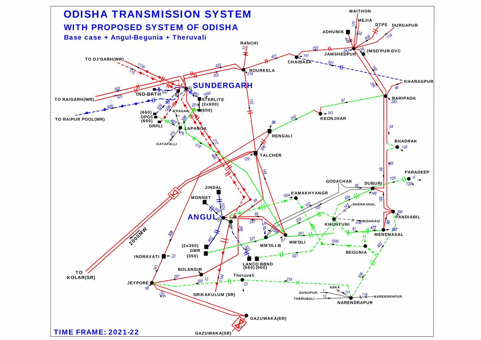
C. Case B + Angul – Begunia 765kV D/c (Hexa Zebra)
In the absence of 400kV LILOs of Talcher –Meramundali and Meramundali –
Bolangir at Angul, major load centres of Odisha (Meramundali, Duburi, Pandiabil
and Mendhasal) are fed through long lines from Lapanga and Baripada. To
relieve the loading of these lines, Odisha’s proposal of Angul – Begunia 765kV
D/c line (via Kamakhyanagar - however without generation) has been studied. A
new 2x1500MVA 765/400kV S/s has been created at Begunia with Angul –
Begunia 765kV D/c line along with LILO of Pandiabil – Narendrapur 400kV D/c
line and Khuntuni – Mendhasal 400kV D/c lines. About 1500MW of power flows
from Angul to Begunia, out of which about 450-500MW flows to each Pandiabil
and Mendhasal and about 600-650MW flows to Narendrapur. With this power
27

flow further increases on Narendrapur – Theruvali – Jeypore 400kV D/c line to
about 300MW.
D. Case C + Talcher-III System
The evacuation system of Talcher-III is Talcher-III – Meramundali/ Meramundali-
B 400kV D/c (triple Snowbird) line (one circuit terminated at Meramundali and
other circuit terminated at Meramundali-B). In this case, there is no power
evacuation problem from Talcher-III and loading on the corridors are within safe
limits.
E. Case D + 3x800MW Kamakhyanagar generation of Odisha
Odisha is setting up 3x800MW generation at Kamakhyanagar. The evacuation
system of Kamakhyanagar generation as proposed by Odisha is LILO of Angul –
Begunia 765kV D/c line at generation switchyard. In this case, about 700MW of
power flows towards and Angul and about 1500MW flows towards Begunia.
About 300MW power is observed to flow from Theruvali to Jeypore. The fault
level of Gazuwaka is expected to be about 5.1kA.
E’. Case E with Angul – Narendrapur – Gazuwaka system in place of
Narendrapur – Theruvali – Jeypore
As compared to case E, about 550MW power is observed to flow from
Narendrapur to Gazuwaka. The fault level of Gazuwaka is expected to about
7.8kA (compared to 5.1kA in previous case).
E”. Case E with Rourkela – Talcher – Behrampur – Gazuwaka system in place
of Narendrapur – Theruvali – Jeypore
In case the Reliance system revives, case E with Rourkela – Talcher –
Behrampur – Gazuwaka 400kV has been studied. About 450MW power is
expected to flow from Behrampur to Gazuwaka and the fault level of Gazuwaka
is expected to about 6.7 kA.
28

Case A Case B Case B' Case C Case D Case E Case E' Case E''
Base caseCase A +
Theruvali
Case A + Angul
Gazuwaka
Case B + Angul
Begunia
Case C + Talcher‐
III
Case D +
kamakhyanagar
Case E + Angul
Gazuwaka
minus Theruvali
Case E + Talcher‐
Behrampur
minus Theruvali
400 kV
JEYPORE 6.8 8.7 9.1 9.5 9.6 9.7 9.5 8.9
JHARSUGUDA 40.5 40.5 40.5 40.6 40.7 40.9 40.9 41.1
ANGUL 38.6 38.6 42.1 41.0 41.2 43.7 46.2 43.6
BEGUNIA ‐ ‐ ‐ 27.0 28.0 29.3 30.9 28.3
MERAMUNDLI 26.9 27.0 28.6 31.3 37.3 37.6 38.2 38.3
MERAMNDLI‐B 26.4 26.4 28.0 30.6 36.5 36.9 37.5 37.5
JHARSU‐SPLI 47.8 47.8 47.9 47.8 48.2 48.6 48.6 48.7
GAZUWAKA‐ER 4.2 4.8 7.4 5.0 5.1 5.1 7.8 6.7
TALCHER‐III ‐ ‐ ‐ ‐ 30.9 31.1 31.5 31.5
NARENDRAPUR 6.2 8.4 13.8 11.3 11.5 11.6 16.4 9.2
765 kV
ANGUL 26.8 26.8 27.9 30.4 30.7 35.0 35.3 34.9
JHARSUGUDA 36.9 36.9 37.1 37.4 37.5 38.2 38.3 38.3
BEGUNIA ‐ ‐ ‐ 16.7 17.0 19.2 19.2 18.9
KAMAKHYANAG ‐ ‐ ‐ 22.2 22.4 27.9 27.9 27.8
JHARSU‐SPLI 29.3 29.3 29.4 29.7 29.8 30.5 30.5 30.5
Fault Current (in kA)
29

GMR
SRIKAKULUM (SR)
MONNET
JINDAL
LANCO BBND
ANGUL
MM'DLI-B
TALCHER
MM'DLI
BOLANGIR
DUBURI
OPGC
DRPLI
SUNDERGARH
STERLITE
IND-BRTH
TO RAIGARH(WR)
TO RAIPUR POOL(WR)
TO DJ'GARH(WR)
ROURKELA
LAPANGA
ODISHA TRANSMISSION SYSTEM
TIME FRAME: 2021-22
PANDIABIL
BARIPADA
B'PADAR
NARENDRAPUR
KATAPALLI
THERUBALI
ASKA
NARENDRAPUR
DHENKANAL
BIDANASI
MENDHASAL
RENGALI
KEONJHAR
JEYPORE
JAMSHEDPUR
CHAIBASA
JMSD'PUR-DVC
KHARAGPUR
RANCHI
ADHUNIK
DTPS
DURGAPUR
MAITHON
MEJIA
TO
KOLAR(SR)
2
0
0
0
M
W
GODACHAK
GUNUPUR
KHUNTUNI
WITH PROPOSED SYSTEM OF ODISHA
INDRAVATI
GAZUWAKA(ER)
GAZUWAKA(SR)
A
B
A
B
BHADRAK
(660)
(660)
(3x600)
(600)
(2x350)
(350)
(660) (660)
Base case
PARADEEP
30

GMR
SRIKAKULUM (SR)
MONNET
JINDAL
LANCO BBND
ANGUL
MM'DLI-B
TALCHER
MM'DLI
BOLANGIR
DUBURI
OPGC
DRPLI
SUNDERGARH
STERLITE
IND-BRTH
TO RAIGARH(WR)
TO RAIPUR POOL(WR)
TO DJ'GARH(WR)
ROURKELA
LAPANGA
ODISHA TRANSMISSION SYSTEM
TIME FRAME: 2021-22
PANDIABIL
BARIPADA
B'PADAR
NARENDRAPUR
KATAPALLI
THERUBALI
ASKA
NARENDRAPUR
DHENKANAL
BIDANASI
MENDHASAL
RENGALI
KEONJHAR
JEYPORE
JAMSHEDPUR
CHAIBASA
JMSD'PUR-DVC
KHARAGPUR
RANCHI
ADHUNIK
DTPS
DURGAPUR
MAITHON
MEJIA
TO
KOLAR(SR)
2
0
0
0
M
W
GODACHAK
GUNUPUR
KHUNTUNI
WITH PROPOSED SYSTEM OF ODISHA
INDRAVATI
GAZUWAKA(ER)
GAZUWAKA(SR)
A
B
A
B
BHADRAK
(660)
(660)
(3x600)
(600)
(2x350)
(350)
(660) (660)
Base case + Theruvali
PARADEEP
Theruvali
31

GMR
SRIKAKULUM (SR)
MONNET
JINDAL
LANCO BBND
ANGUL
MM'DLI-B
TALCHER
MM'DLI
BOLANGIR
DUBURI
OPGC
DRPLI
SUNDERGARH
STERLITE
IND-BRTH
TO RAIGARH(WR)
TO RAIPUR POOL(WR)
TO DJ'GARH(WR)
ROURKELA
LAPANGA
ODISHA TRANSMISSION SYSTEM
TIME FRAME: 2021-22
PANDIABIL
BARIPADA
B'PADAR
NARENDRAPUR
KATAPALLI
THERUBALI
ASKA
NARENDRAPUR
DHENKANAL
BIDANASI
MENDHASAL
RENGALI
KEONJHAR
JEYPORE
JAMSHEDPUR
CHAIBASA
JMSD'PUR-DVC
KHARAGPUR
RANCHI
ADHUNIK
DTPS
DURGAPUR
MAITHON
MEJIA
TO
KOLAR(SR)
2
0
0
0
M
W
GODACHAK
GUNUPUR
KHUNTUNI
WITH PROPOSED SYSTEM OF ODISHA
INDRAVATI
GAZUWAKA(ER)
GAZUWAKA(SR)
A
B
A
B
BHADRAK
(660)
(660)
(3x600)
(600)
(2x350)
(350)
(660) (660)
Base case + Angul-Gazuwaka
PARADEEP
32
GMR
SRIKAKULUM (SR)
MONNET
JINDAL
LANCO BBND
ANGUL
MM'DLI-B
TALCHER
MM'DLI
BOLANGIR
DUBURI
OPGC
DRPLI
SUNDERGARH
STERLITE
IND-BRTH
TO RAIGARH(WR)
TO RAIPUR POOL(WR)
TO DJ'GARH(WR)
ROURKELA
LAPANGA
ODISHA TRANSMISSION SYSTEM
TIME FRAME: 2021-22
PANDIABIL
BARIPADA
B'PADAR
NARENDRAPUR
KATAPALLI
THERUBALI
ASKA
NARENDRAPUR
DHENKANAL
BIDANASI
MENDHASAL
RENGALI
KEONJHAR
JEYPORE
JAMSHEDPUR
CHAIBASA
JMSD'PUR-DVC
KHARAGPUR
RANCHI
ADHUNIK
DTPS
DURGAPUR
MAITHON
MEJIA
TO
KOLAR(SR)
2
0
0
0
M
W
GODACHAK
GUNUPUR
KHUNTUNI
WITH PROPOSED SYSTEM OF ODISHA
INDRAVATI
GAZUWAKA(ER)
GAZUWAKA(SR)
A
B
A
B
BHADRAK
(660)
(660)
(3x600)
(600)
(2x350)
(350)
(660) (660)
Base case + Angul-Begunia + Theruvali
PARADEEP
Theruvali
BEGUNIA
KAMAKHYANGR
33

GMR
SRIKAKULUM (SR)
MONNET
JINDAL
LANCO BBND
ANGUL
MM'DLI-B
TALCHER
MM'DLI
BOLANGIR
DUBURI
OPGC
DRPLI
SUNDERGARH
STERLITE
IND-BRTH
TO RAIGARH(WR)
TO RAIPUR POOL(WR)
TO DJ'GARH(WR)
ROURKELA
LAPANGA
ODISHA TRANSMISSION SYSTEM
TIME FRAME: 2021-22
PANDIABIL
BARIPADA
B'PADAR
NARENDRAPUR
KATAPALLI
THERUBALI
ASKA
NARENDRAPUR
DHENKANAL
BIDANASI
MENDHASAL
RENGALI
KEONJHAR
JEYPORE
JAMSHEDPUR
CHAIBASA
JMSD'PUR-DVC
KHARAGPUR
RANCHI
ADHUNIK
DTPS
DURGAPUR
MAITHON
MEJIA
TO
KOLAR(SR)
2
0
0
0
M
W
GODACHAK
GUNUPUR
KHUNTUNI
WITH PROPOSED SYSTEM OF ODISHA
INDRAVATI
GAZUWAKA(ER)
GAZUWAKA(SR)
A
B
A
B
BHADRAK
(660)
(660)
(3x600)
(600)
(2x350)
(350)
(660) (660)
TALCHER-III
Base case + Angul-Begunia + Talcher-III + Theruvali
PARADEEP
Theruvali
BEGUNIA
(2x660)
KAMAKHYANGR
34

GMR
SRIKAKULUM (SR)
MONNET
JINDAL
LANCO BBND
ANGUL
MM'DLI-B
TALCHER
MM'DLI
BOLANGIR
DUBURI
OPGC
DRPLI
SUNDERGARH
STERLITE
IND-BRTH
TO RAIGARH(WR)
TO RAIPUR POOL(WR)
TO DJ'GARH(WR)
ROURKELA
LAPANGA
ODISHA TRANSMISSION SYSTEM
TIME FRAME: 2021-22
PANDIABIL
BARIPADA
B'PADAR
NARENDRAPUR
KATAPALLI
THERUBALI
ASKA
NARENDRAPUR
DHENKANAL
BIDANASI
MENDHASAL
RENGALI
KEONJHAR
JEYPORE
JAMSHEDPUR
CHAIBASA
JMSD'PUR-DVC
KHARAGPUR
RANCHI
ADHUNIK
DTPS
DURGAPUR
MAITHON
MEJIA
TO
KOLAR(SR)
2
0
0
0
M
W
GODACHAK
GUNUPUR
KHUNTUNI
WITH PROPOSED SYSTEM OF ODISHA
INDRAVATI
GAZUWAKA(ER)
GAZUWAKA(SR)
A
B
A
B
BHADRAK
(660)
(660)
(3x600)
(600)
(2x350)
(350)
(660) (660)
TALCHER-III
Base case + Talcher-III + Angul - Begunia + Kamakhyangr + Theruvali
PARADEEP
Theruvali
BEGUNIA
(2x660)
KAMAKHYANGR
(3x800)
35

GMR
SRIKAKULUM (SR)
MONNET
JINDAL
LANCO BBND
ANGUL
MM'DLI-B
TALCHER
MM'DLI
BOLANGIR
DUBURI
OPGC
DRPLI
SUNDERGARH
STERLITE
IND-BRTH
TO RAIGARH(WR)
TO RAIPUR POOL(WR)
TO DJ'GARH(WR)
ROURKELA
LAPANGA
ODISHA TRANSMISSION SYSTEM
TIME FRAME: 2021-22
PANDIABIL
BARIPADA
B'PADAR
NARENDRAPUR
KATAPALLI
THERUBALI
ASKA
NARENDRAPUR
DHENKANAL
BIDANASI
MENDHASAL
RENGALI
KEONJHAR
JEYPORE
JAMSHEDPUR
CHAIBASA
JMSD'PUR-DVC
KHARAGPUR
RANCHI
ADHUNIK
DTPS
DURGAPUR
MAITHON
MEJIA
TO
KOLAR(SR)
2
0
0
0
M
W
GODACHAK
GUNUPUR
KHUNTUNI
WITH PROPOSED SYSTEM OF ODISHA
INDRAVATI
GAZUWAKA(ER)
GAZUWAKA(SR)
A
B
A
B
BHADRAK
(660)
(660)
(3x600)
(600)
(2x350)
(350)
(660) (660)
TALCHER-III
Base case + Talcher-III + Angul - Begunia + Kamakhyangr + Angul - Gaz
PARADEEP
BEGUNIA
(2x660)
KAMAKHYANGR
(3x800)
36

GMR
SRIKAKULUM (SR)
MONNET
JINDAL
LANCO BBND
ANGUL
MM'DLI-B
TALCHER
MM'DLI
BOLANGIR
DUBURI
OPGC
DRPLI
SUNDERGARH
STERLITE
IND-BRTH
TO RAIGARH(WR)
TO RAIPUR POOL(WR)
TO DJ'GARH(WR)
ROURKELA
LAPANGA
ODISHA TRANSMISSION SYSTEM
TIME FRAME: 2021-22
PANDIABIL
BARIPADA
B'PADAR
NARENDRAPUR
KATAPALLI
THERUBALI
ASKA
NARENDRAPUR
DHENKANAL
BIDANASI
MENDHASAL
RENGALI
KEONJHAR
JEYPORE
JAMSHEDPUR
CHAIBASA
JMSD'PUR-DVC
KHARAGPUR
RANCHI
ADHUNIK
DTPS
DURGAPUR
MAITHON
MEJIA
TO
KOLAR(SR)
2
0
0
0
M
W
GODACHAK
GUNUPUR
KHUNTUNI
WITH PROPOSED SYSTEM OF ODISHA
INDRAVATI
GAZUWAKA(ER)
GAZUWAKA(SR)
A
B
A
B
BHADRAK
(660)
(660)
(3x600)
(600)
(2x350)
(350)
(660) (660)
Base case + Angul-Begunia + Kamakhyanagar + Talcher-III + Talcher-Gaz
PARADEEP
BEGUNIA
KAMAKHYANGR
BEHRAMPUR
37
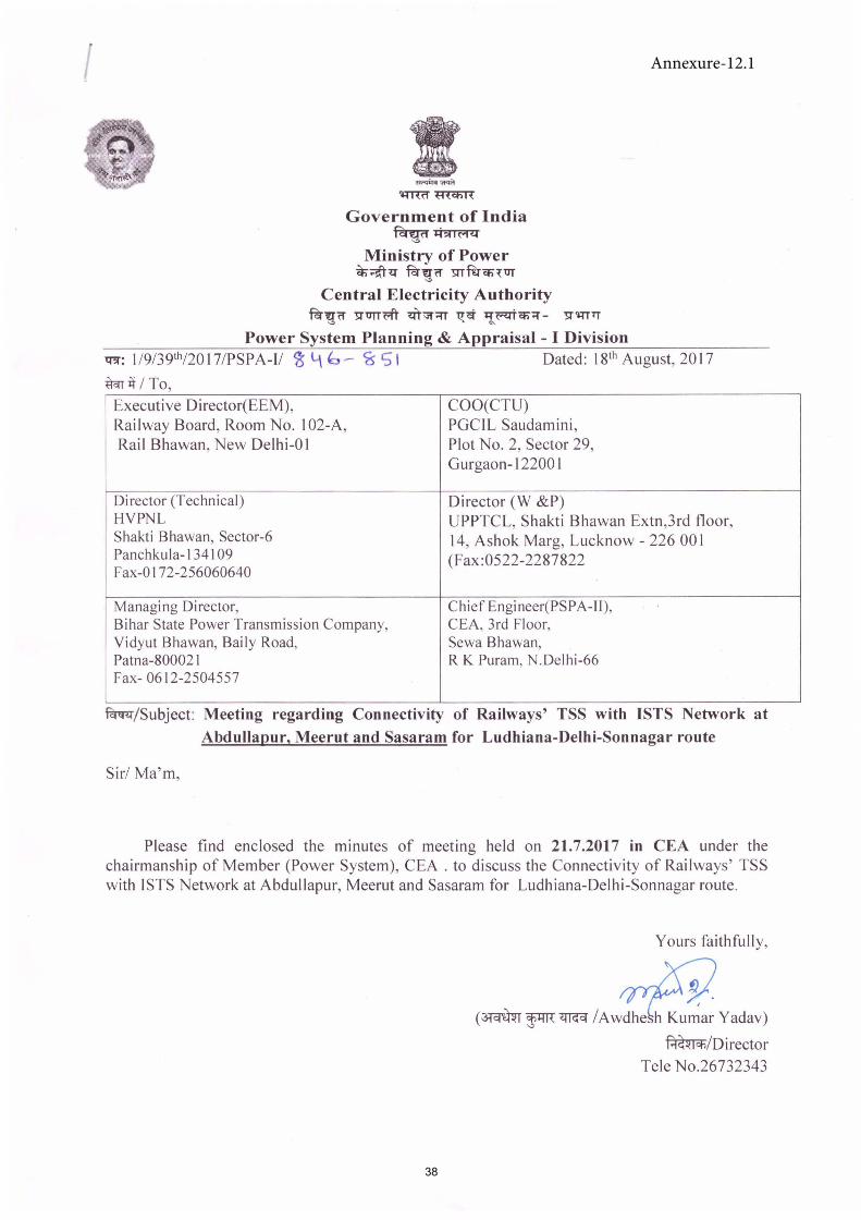
..,,,;,,, """' m«f mi.nR
Government of India ~+:i~IM<..I
"' Ministry of Power
~~.:i- Pcn:ro '51Tfu°ct;TUT '"'
Central Electricity Authority Pcnrn 'l:l"'OTTm ...,.~;::rr l1'. ct ~('<..IT q;-;:r - '!:I" ,qpr
'"' ~
Power System Planning & Appraisal - I Division q;r: J/9/39th/2017/PSPA-I/ 1$ l\ '=, ~ <is" SI Dated: Jgth August, 2017
mnit I To, Executive Director(EEM), COO(CTU) Railway Board, Room No. I 02-A, PGCIL Saudamini, Rail Bhawan, New Delhi-OJ Plot No. 2, Sector 29,
Gurgaon-12200 I
Director (Technical) Director (W &P) HYPNL UPPTCL, Shakti Bhawan Extn,3rd floor, Shakti Bhawan, Sector-6 14, Ashok Marg, Lucknow - 226 00 I Panchkula-134109 (Fax:0522-2287822 Fax-0172-256060640
Managing Director, Chief Engineer(PSPA-11), Bihar State Power Transmission Company, CEA, 3rd Floor, Yidyut Bhawan, Baily Road, Sewa Bhawan, Patna-800021 R K Puram, N.Delhi-66 Fax-0612-2504557
~ / Subject: Meeting regarding Connectivity of Railways' TSS with ISTS Network at Abdullapur, Meerut and Sasaram for Ludhiana-Delhi-Sonnagar route
Sir/ Ma'm,
Please find enclosed the minutes of meeting held on 21.7.2017 in CEA under the chairmanship of Member (Power System), CEA . to discuss the Connectivity of Railways' TSS with ISTS Network at Abdullapur, Meerut and Sasaram for Ludhiana-Delhi-Sonnagar route.
Yours faithfully,
(
(~~~ /Awdhe h KumarYadav)
~/Director Tele No.26732343
Annexure-12.1
38
Minutes of Meeting held at CEA on 21.07.2017 regarding Connectivity of Railways' Traction Sub Station (TSS) with ISTS Network at Abdullapur, Meerut and Sasaram for Ludhiana-DelhiSomnagar route.
List of participants is attached as Annexure-1.
I. Member (PS) welcomed the participants. He stated that in line with the decision of the 391" meeting of
Standing Committee on Power System Planning in Northern Region, this meeting has been convened to discuss the Connectivity of Railways' TSSs with ISTS Network at Abdullapur & Meerut (in Northern region) and Sasaram (in Eastern Region) for Ludhiana-Delhi-Somnagar Railway route.
2. UPPTCL stated that before taking up the individual cases for discussion, the financial viability of the Railways' proposal of getting connected with ISTS needs to be discussed and same was also deliberated in the previous meeting of Standing Committee ofNR. The switchover/withdrawal from STU network to ISTS has to be gradual, so that STU gets adequate time to plan utilization of their network. In Uttar Pradesh, they had received a number of applications from Railways as DISCOM's HT customer for drawing power from the State network. If all these loads are sanctioned, corresponding augmentation in the Transmission network of UP would also be required to meet the additional load. If Railways takes ISTS connectivity and switches its load from state network to ISTS network, then the network / augmentation in UP network for catering to Railways' load would become idle / underutilized. Therefore, Railways' needs to first decide, either to continue as DISCOM's HT consumer or get connected to ISTS directly. Due to this uncertainty, they were not in a position to take any decision on the load applications submitted by Railways.
3. Indian Railways clarified that they have to meet their traction load requirements, which can be catered either through state network or through open access by getting connectivity with ISTS network. Till the establishment of connectivity with the ISTS network, they would continue to apply' as DISCOM's HT consumer of the respective state for meeting their traction load requirements. Further, since Indian Railways is not getting NoC for Open Access from STU 's, they had been seeking connectivity as
DISCOM's HT customer.
4. CEA clarified that in the recently held Standing Committee meeting ofNR on 29'"-301" May 2017, two
cases of connectivity to Railways were discussed. First case was connectivity of Railways' TSS with ISTS Network for Delhi - Bharuch route wherein, it was agreed that Railways would once again look into the cost economics of connectivity to ISTS points as number of the States had already granted / were in the process of granting no objection certificate for open access to Railways from their network and would share the same with CEA. The second case was Connectivity of Railways' TSS with ISTS Network for Ludhiana-Delhi-Sonnagar route. This meeting has been called to discuss the ISTS connectivity of Railways at Meerut, Abdullapur and Sasaram ISTS substations for the Ludhiana-DelhiSonnagar route. The connectivity sought by Indian Railways with lSTS Network at Abdullapur, Meerut and Sasaram needs to be viewed in isolation as no STU network exists in parallel from these ISTS points. As far as the overall plan of Railway for getting connectivity is concerned, Railways needs to rework their cost economics in view of the state's willingness to provide open access to Railway. It was stated that in case UP agrees to provide open access to Railways through their intra state transmission system, then the augmentation in intra state Transmission network of UP would be
required for providing open access to Railways in their network.
5. After that connectivity to Railways at Meerut and Abdullapur was discussed.
220 kV Connectivity at Meerut 400/220 kV substation:
POWERGRID informed that space at Meerut 400/220 kV S/s is available for implementation of only one no. of220 kV bay (AIS) or 2 nos. of 220kV GIS bays. It was also informed that space is available
39

in the substation for creation of 2201132 kV, 2xl 00 MVA GlS at Meerut sub-station and Railways can draw power through 132 kV Die line.
CEA suggested that instead of creating 2201132 kV GIS at Meerut sub-station, 220 kV Sic line emanating from Meerut sub-station can be constructed as deposit work for Indian Railways. Further Indian Railways can construct 2201132 kV sub-station on its own and can draw power at 132 kV level.
POWERGRlD stated that due to severe RoW constraints, some portion of the line needs to be implemented as cable and laying of 132 kV line would be economical instead of220 kV line. Therefore, creation of2201132 kV GIS at Meerut sub-station and drawl of power through 132 kV Die line would be economical to Railways. The 132kV Die feeder would be a combination of overhead line and cable.
Railways agreed to the proposal of creation of2201132 kV GlS at Meerut sub-station for further supply of power their traction sub-stations and the cost for the works would be borne by Railways.
220 kV Connectivity at Abdullapur 4001220 kV substation:
POWERGRID informed that at Abdullapur 4001220 kV substation Railways is drawing power through two no. of 220 kV bays for their Jagadhari TSS. HVPNL confirmed that the line is being exclusively used by Railways and is drawing 10-15 MW power at present.
CEA stated that instead of getting additional 220 kV connectivity at Abdullapur, the connectivity already provided at Abdullapur may be utilized by Railways for feeding their additional traction load. HVPNL agreed with proposal and stated the they have no objection for carrying out the necessary technical upgradation of the 220 kV line ( presently only two phases has been strung) by railway to meet their traction load requirements subject to fulfilment of all the existing commercial agreement of HVPNL with Railways for this line.
After detailed deliberations, the following decisions were taken:
(i) Railways would utilize existing two number of220 kV bays at Abdullapur substation (presently used for 220 kV supply to Jagadhari TSS) to meet their additional traction load requirement. The required technical upgradation of the 220 kV line (presently only two phases has been strung) would be carried out by Railways subject to fulfilment of all the existing agreements of HVPNL with Railways for this line.
(ii) T\VO nos. of 220 kV (GlS) bays at Meerut 4001220 kV substation along with establishment of 2201132 kV, 2xl 00 MVA GIS in the premises ofMeerut 4001220 kV substation was agreed for providing connectivity to Railways. The cost of above works shall be borne by Railways. Railways to implement 132kV Die interconnection from Meerut (PG) to their 132kV substation.
(iii) As no representative from Bihar was present in the meeting, no decision could be taken in respect of connectivity to Railways TSS at Sasaram substation.
(iv) Indian Railways agreed to apply afresh for open access from UPPTCL instead of seeking connectivity as DISCOM's HT customer. UPPTCL agreed to consider Railways application for open access from their network.
(v) Railways to carry out economic analysis of seeking connect1v1ty through ISTS points considering LTA cost, RoW compensation cost etc. vis-a-vis seeking open access from STUs.
e meeting ended with thanks to chair.
40
Annexure-1
List of Participants of the Meeting on the subject Connectivity of Railways TSS with ISTS network at Abdullapur, Meerut and Sasaram dated 21.07.2017
SI. Name Designation
No. Shri/Smt
I. CEA
I. Prakash Mhaske - Member 2. Ravinder Gupta - Chief Engineer, (PSPA-1) " S.K. Ray Mahapatra - Chief Engineer, (PSPA-11) .) .
4. A wdhesh Kumar Yadav - Director (PSPA-1) 5. Rishika Sharma - Director 6. U.M.Rao - Dy. Director 7. Priyam Srivastava - Assistant Director 8. Jitesh Srivas - Assistant Director
II. Ministry of Railway
9. Punit Agarwal - Director 10. K.R. Meena - Dy.(EE/P) 11. P.K. Bhatt -AEE
III. POWERGRID
11. Rashm i Pant Joshi - Manager 12. Mukesh Khanna -AGM
IV. UPTCL
13. Suman Guchh - Chief Engineer (Trans Planning)
V. HVPNL
14. Rakesh Jolly -CE 15. M.M. Matle - SE
41
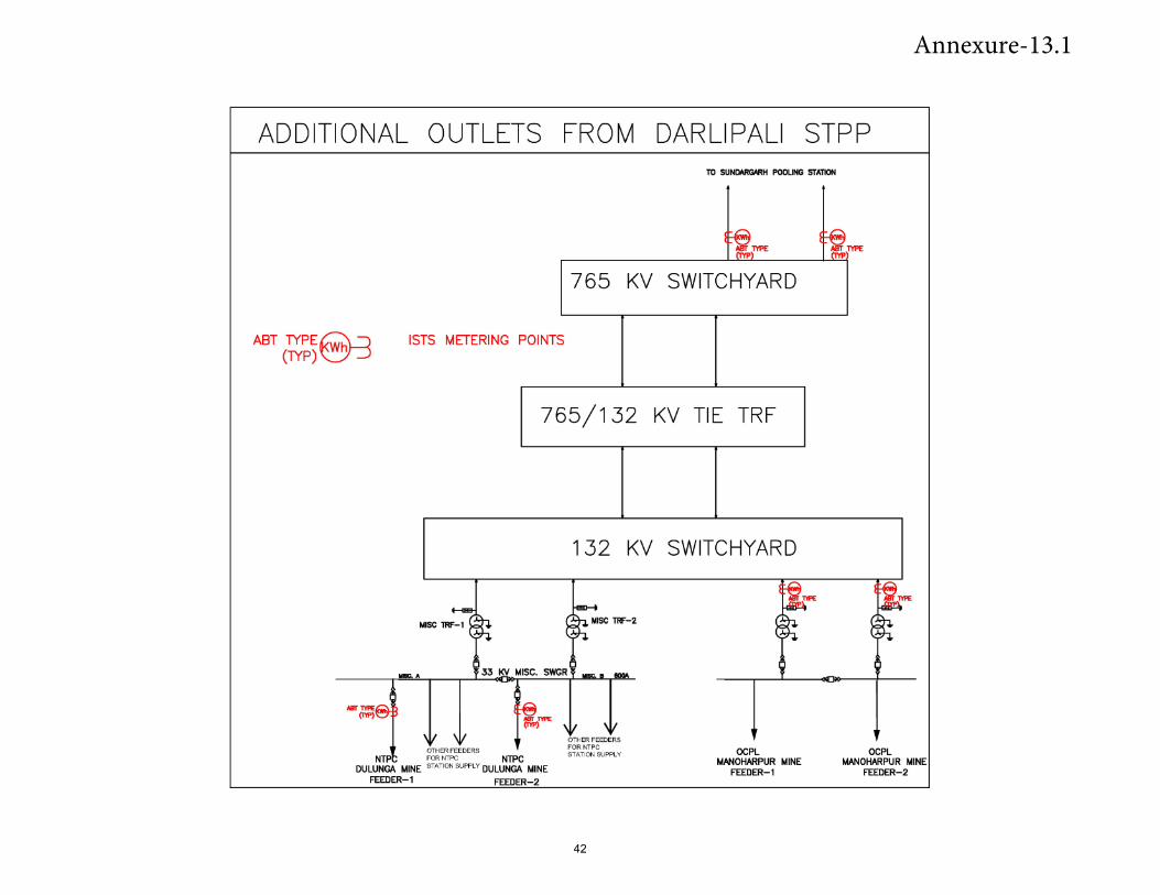
ADDITIONAL OUTLETS FROM DARLIPALI STPP
ABT TYPE~ (TYP)~
ISTS METERING POINTS
10 SUNDAAGAAH POOLING STATION
TYPE
765 KV SWITCHYARD
765/132 KV TIE TRF
NirlYPE (nP)
33 KV MISC. SWGR
OTHER FEEDERS NTP FOR NTPC NTPC
DULUNGA MINE STATI ON SUPPLY DULUNGA MINE FEEDER-1 FEEDER-2
132 KV SWITCHYARD
MISC TRF-2
OTHER FEEDERS FOR NTPC STATION SU PPLY OCPL
MANOHARPUR MINE FEEDER-1
TYPE
1 OCPL
MANOHARPUR MINE FEEDER-2
Annexure-13.1
42

43