ADDENDUM NO. 1 - South Bend Heritage Foundation, South...
63
ADDENDUM NO. 1 RE: PERMANENT SUPPORTIVE HOUSING DATE: September 16, 2016 924 West Indiana Avenue South Bend, Indiana TO: All Bidders Gentlemen: You are hereby directed to make the following changes in the Project Manual and/or Drawings of the subject job and each item shall become fully a part of the Construction Documents as if originally written and/or shown: 1. SPECIFICATIONS ; DAVIS-BACON CONTRACT PROVISIONS; has been included (see attached Exhibit G). 2. SPECIFICATIONS ; 00 20 00 - INSTRUCTIONS TO BIDDERS ; 11. BID SUBMITTAL; add the following: Proposal for: Bid package Subdivision # 30 Bid package Name: Plumbing 3. SPECIFICATIONS ; 0 41 00 - BID FORM ; has been revised in its entirety (see attached). 4. SPECIFICATIONS ; 00 90 00 - SCOPE OF WORK ; has been revised in its entirety (see attached). Changes are highlighted in yellow. 5. SPECIFICATIONS ; 01 23 00 - ALTERNATES ; C. EXECUTION; 1, REQUIRED ALTERNATES: a. Revise Alternate No. 9 bid package reference to BPS-30, and revise shower enclosure type to SH-2. b. Revise Alternate No. 10 bid package reference to BPS-24. c. Revise Alternate No. 11 bid package reference to BPS-24. d. Revise Alternate No. 12 bid package reference to BPS-24. e. Add Alternate No. 13 as follows: 13) Alternate No. 13 Reference Addendum Exhibit ADD 1-19 (attached). Revise stair enclosure configuration as shown. Eliminate storefront framing system and entry door. Revise exterior finishes as shown. 6. SPECIFICATIONS; 07 46 46 - FIBER CEMENT CLADDING, SIDING AND ACCESSORIES ; B. PRODUCTS: a. Under 2. LAP SIDING AND ACCESSORIES: 1) Item c. Trim ; shall be revised to read, “5/4 Smooth Boards”. 2) Item c. Trim ; 2) Thickness; shall be revised to 1".
Transcript of ADDENDUM NO. 1 - South Bend Heritage Foundation, South...

ADDENDUM NO. 1
RE: PERMANENT SUPPORTIVE HOUSING DATE: September 16, 2016924 West Indiana AvenueSouth Bend, Indiana
TO: All Bidders
Gentlemen:
You are hereby directed to make the following changes in the Project Manual and/or Drawings of the subjectjob and each item shall become fully a part of the Construction Documents as if originally written and/orshown:
1. SPECIFICATIONS; DAVIS-BACON CONTRACT PROVISIONS; has been included (see attachedExhibit G).
2. SPECIFICATIONS; 00 20 00 - INSTRUCTIONS TO BIDDERS; 11. BID SUBMITTAL; add thefollowing:
Proposal for:Bid package Subdivision # 30Bid package Name: Plumbing
3. SPECIFICATIONS; 0 41 00 - BID FORM; has been revised in its entirety (see attached).
4. SPECIFICATIONS; 00 90 00 - SCOPE OF WORK; has been revised in its entirety (see attached). Changes are highlighted in yellow.
5. SPECIFICATIONS; 01 23 00 - ALTERNATES; C. EXECUTION; 1, REQUIRED ALTERNATES:
a. Revise Alternate No. 9 bid package reference to BPS-30, and revise shower enclosure typeto SH-2.
b. Revise Alternate No. 10 bid package reference to BPS-24.
c. Revise Alternate No. 11 bid package reference to BPS-24.
d. Revise Alternate No. 12 bid package reference to BPS-24.
e. Add Alternate No. 13 as follows:
13) Alternate No. 13Reference Addendum Exhibit ADD 1-19 (attached). Revise stair enclosureconfiguration as shown. Eliminate storefront framing system and entrydoor. Revise exterior finishes as shown.
6. SPECIFICATIONS; 07 46 46 - FIBER CEMENT CLADDING, SIDING AND ACCESSORIES;B. PRODUCTS:
a. Under 2. LAP SIDING AND ACCESSORIES:
1) Item c. Trim; shall be revised to read, “5/4 Smooth Boards”.
2) Item c. Trim; 2) Thickness; shall be revised to 1".

ADDENDUM NO. 1 -2- September 16, 2016
b. Add items 3 and 4 as follows:
3. METAL LOUVER
a. Thin-line Louver, J Style Blade, Model No. ESJ-150 asmanufactured by Greenheck, including flange, insect screen. Kynar Finish: Color selected by the Architect.
4. PRE-FINISHED METAL SIDING
a. "S" deck, 0.032 aluminum, corrugated profile, exposed metalfastener, as manufactured by Berridge Manufacturing Company,Basis of design shall meet the following criteria:1) Aluminum Sheet: Coil-coated sheet, ASTM B 209, 3105
alloy as standard with manufacturer, with H14 temper asrequired to suit forming operations and structuralperformance required.a) Thickness: 0.032 inch.b) Surface: Corrugated, smooth.c) Exterior Finish: Two-coat fluoropolymer.d) Color: As selected by Architect from
manufacturer's full range of colors.e) Rib Spacing: 2.67 inches o.c.f) Panel Coverage: 32 inches.g) Panel Height: 0.875 inch (22 mm).
2) Felt Underlayment: ASTM D 226/D 22M, Type II (No. 30),asphalt-saturated organic felts.
7. SPECIFICATIONS; 08 41 13 - ALUMINUM STOREFRONT FRAMING AND WINDOWS; B. PRODUCTS;3. SPECIFIC PRODUCT REQUIREMENTS; shall be revised to read as follows:
a. Exterior Storefront System: 1) Exterior Storefront System to be equal to:
(i) Tubelite 14000 Series. 2" W x 4½" D x .125" wall thickness.
b. Glazing: Basis of Design: Guardian SunGuard SuperNeutral 62.Other acceptable manufacturers: equivalent glazing systems by Pilkington, Viracon,or PPG.
c. Provide glass with strength required to withstand structural and thermalrequirements listed in this section. Provide heat-strengthened glass generally. Usetempered glass on the inboard lite of all glass less than 30" above finished floor(AFF).1) Exterior Lite: ¼ inch clear.2) Air Space: ½ inch.3) Interior Lite: ¼ inch clear with SuperNeutral 62. 4) Light Transmittance:
(i) Daylight: 62 percent; Solar: 27 percent; UV: 14 percent.(ii) Shading Coefficient: 0.36; SHGC: 0.31.(iii) Insulating (U) Value:
(a) Summer: 0.27.(b) Winter: 0.29.

ADDENDUM NO. 1 -3- September 16, 2016
8. SPECIFICATIONS; 08 52 13 - CLAD WOOD WINDOWS; A GENERAL; 4. PERFORMANCEREQUIREMENTS; add the following:
d. Performance Information: 1) Fixed Unit: U-Factor 0.28; SHGC 0.31, VLT 0.58, CPD
PEL-N-22-00526-00001, Performance Class R, PG 50, Calculated PositiveDP Rating 50, Calculated Negative DP Rating 50.
2) Operable Unit: U-Factor 0.29; SHGC 0.27, VLT 0.52, CPDPEL-N-37-00369-00001, Performance Class R, PG 50, Calculated PositiveDP Rating 50, Calculated Negative DP Rating 50.
9. SPECIFICATIONS; 08 81 00 - GLAZING; has been added (see attached).
10. SPECIFICATIONS; 11 30 00 - RESIDENTIAL EQUIPMENT; has been revised in its entirety (seeattached).
11. SPECIFICATIONS; 12 35 30 - CASEWORK; B. PRODUCTS:
a. Under 4. LAMINATE COVERED WOOD CABINETS AND SHELVES; item “a”; first sentenceshall be revised to read, “Wood cabinets in Reception, Healthcare, Office Workroom,Community Room Kitchen, Media Center and Laundry to have minimum construction andfinish requirements as follows.”
b. Under 6. SOLID SURFACE MATERIAL COUNTERTOPS; revise title to read, “SOLIDSURFACE MATERIAL COUNTERTOPS/WINDOW STOOLS”.
12. SPECIFICATIONS; 12 35 35 - CASEWORK - APARTMENTS; has been added (see attached).
13. SPECIFICATIONS; 21 02 00 - FIRE PROTECTION GENERAL PROVISIONS; B. MATERIALS ANDINSTALLATION; item 1:
a. Under a. Sprinkler Heads; item 1; sub-item c) “All areas with suspended acoustical tileceiling”; shall be revised to read as follows:
c) All Areas with Suspended Acoustical Tile Ceiling: Heads shall be fullyconcealed type, white.
b. Under c. Pipe & Fittings; item “1)”; add sub-item “b)” as follows:
b) Ductile iron per ANSI utilizing mechanical joints for threaded connectionsmay be utilized for main runs above Corridor ceilings.
14. SPECIFICATIONS; 26 28 01 - GROUND FAULT PROTECTION; this section has been deleted. Noground fault protection will be provided for the electric service.
15. SPECIFICATIONS; 28 46 00 - FIRE ALARM SYSTEM; A. GENERAL; 2. SCOPE; revise item “c” toread as follows:
c. Boxes and conduit above ceiling shall be furnished and installed by the electricalcontractor. Fire alarm specialty systems contractor to install all equipment andwiring.

ADDENDUM NO. 1 -4- September 16, 2016
16. DRAWINGS; GENERAL:
a. As a general note on all architectural and general sheets, stair enclosure, elevator enclosure,elevator shaft, and elevator machine room shall all be enclosed with one-hour fire barriersin lieu of two-hour shown. Wall construction shall be one layer of 5/8" Type X gypsum boardeach side of the wall.
b. For all wall sections (Sheets A4.1 thru A4.4) and the elevator stair section (Sheets A5.1 andA5.2), revise all notes referring to “3/4" PLYWOOD DECK” to “FLOOR SHEATHING”. Reviseall notes referring to “3/4" PLYWOOD ROOF DECK” to “ROOF SHEATHING”. Revise allnotes referring to “1/2" DENSDECK” roof underlayment to “1/2" RECOVERY BOARD”.
17. DRAWINGS; Sheet No. S1.2; add column and beam connection details as shown on the attachedExhibit ADD1-1.
18. DRAWINGS; Sheet No. S2.1:
a. COLUMN SCHEDULE:
1) Revise Column C3 to 7" x 5¼” PSL.
2) Add Column C5, 3½” x 7" PSL.
b. BEAM & HEADER SCHEDULE:
1) At TAG H6, revise WALL STUD UNDER BEARING to C5 at GND. FLR. and C5 atUPPER FLR.
2) At TAG B1, revise GROUND FLOOR MEMBER to 3½” x 24" Glulam. Revise WALLSTUD UNDER BEARING to Column C2.
3) At TAG B5, revise GROUND FLOOR MEMBER to (3) 1¾” x 9¼” LVL. Bearing wallstuds shill be C3/C3/C3/C4.
4) At TAG B6, revise GROUND FLOOR MEMBER to W12" x 26".
c. UPPER FLOOR FRAMING PLAN; revise bearing walls of Community Room to 2 x 6 framingas shown on the attached Exhibit ADD 1-2. Revise exterior wall of Offices to 2 x 6 framingas shown on the attached Exhibit ADD 1-2.
d. Add DETAILS 2/S2.1 and 3/S2.1 as shown on the attached Exhibit ADD 1-3.
19. DRAWINGS; Sheet No. S2.2; ROOF FRAMING PLAN; revise Beam B9 to B13 (beam located aboveupper floor lobby).
20. DRAWINGS; Sheet No. A1.1; GROUND FLOOR PLAN:
a. Provide fire extinguishers and cabinets to Corridor 100, Lobby 106, and Corridor 130.
b. Provide fire extinguisher and wall-mounted bracket to Kitchen 119 and Maintenance 124.
21. DRAWINGS; Sheet No. A1.2; UPPER LEVEL FLOOR PLAN; provide fire extinguishers and cabinetsto Corridor 200, Lobby 208, and Corridor 230.

ADDENDUM NO. 1 -5- September 16, 2016
22. DRAWINGS; Sheet No. A2.1; DRAIN/SCUPPER DETAIL 1/A2.1; revise detail title to “ROOFDRAIN/OVER FLOW DRAIN DETAIL”. Revised detail shall include sump construction. See attachedExhibit ADD 1-4.
23. DRAWINGS; Sheet No. A2.2; DETAIL 5/A2.2; has been revised (see attached Exhibit ADD 1-5).
24. DRAWINGS; Sheet No. A3.2; WINDOW TYPES; to clarify the intent of the drawings:
a. W1 thru W4: Aluminum or vinyl clad wood windows (all vinyl by alternate).
b. W5 thru W18: Aluminum Frame with 1" insulated glass.
c. Window W3 shall be a combination unit of three (3) clad wood windows in lieu of one (1)shown (See Elevation 4/A3.1).
25. DRAWINGS; Sheet No. A4.2; WALL SECTION 3/A4.2:
a. Provide single wood plate below window in lieu of double wood plate shown.
b. Provide treated 2x blocking at parapet.
26. DRAWINGS; Sheet No. A4.3:
a. WALL SECTION 1/A4.3:
1) Provide single wood plate below window in lieu of double wood plate shown.
2) Reference Wall Sections: Provide treated 2x blocking at parapet.
b. WALL SECTION 2/A4.3:
1) Provide single wood plate below window in lieu of double wood plate shown.
2) Reference Wall Sections: Provide treated 2x blocking at parapet.
27. DRAWINGS; Sheet No. A4.4; WALL SECTION 1/A4.4; has been added (see attached ExhibitADD 1-18).
28. DRAWINGS; Sheet No. A6.1; ENLARGED GROUND FLOOR PLAN; Community Room 118:
a. Change closet door to read, “118-D”.
b. Change entry door, sidelight and borrowed lite to read “118-E”.
29. DRAWINGS; Sheet No. A6.3; DETAIL 6/A6.3; revise Community Room door and borrowed liteelevation (see attached Exhibit ADD 1-20).
30. DRAWINGS; Sheet No. A6.5; add toilet accessories. Provide in each apartment unit bathroom:
- Medicine Cabinet: Recessed Bobrick 397.- Mirror: Mirror Model # B-165 4836, 48" x 36", as manufactured by Bobrick.- Grab Bars: 24" (GB-24), 36" (GB-36), and 42" (GB-42) B5806 Series as manufactured by
Bobrick.- Toilet Paper Holder (TB): Provide one (1) Model No. 01-201S surface toilet paper holder as
manufactured by Taymor.
ADDENDUM NO. 1 -6- September 16, 2016
- Towel Bars (TB18, TB24): At each full bathroom, provide one (1) No. 01-202-18" and one(1) No. 01-202-24" towel bar as manufactured by Taymor.
- Shower Seat: Bobrick Folding Shower Seat B-518
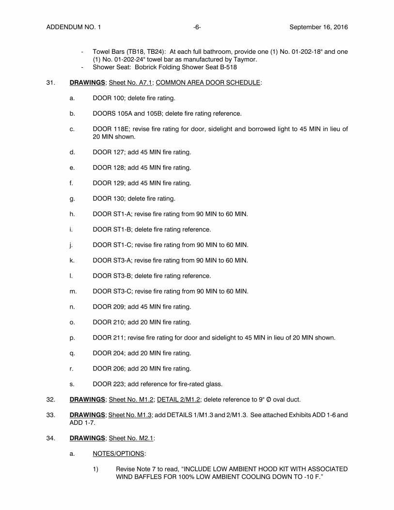
31. DRAWINGS; Sheet No. A7.1; COMMON AREA DOOR SCHEDULE:
a. DOOR 100; delete fire rating.
b. DOORS 105A and 105B; delete fire rating reference.
c. DOOR 118E; revise fire rating for door, sidelight and borrowed light to 45 MIN in lieu of20 MIN shown.
d. DOOR 127; add 45 MIN fire rating.
e. DOOR 128; add 45 MIN fire rating.
f. DOOR 129; add 45 MIN fire rating.
g. DOOR 130; delete fire rating.
h. DOOR ST1-A; revise fire rating from 90 MIN to 60 MIN.
i. DOOR ST1-B; delete fire rating reference.
j. DOOR ST1-C; revise fire rating from 90 MIN to 60 MIN.
k. DOOR ST3-A; revise fire rating from 90 MIN to 60 MIN.
l. DOOR ST3-B; delete fire rating reference.
m. DOOR ST3-C; revise fire rating from 90 MIN to 60 MIN.
n. DOOR 209; add 45 MIN fire rating.
o. DOOR 210; add 20 MIN fire rating.
p. DOOR 211; revise fire rating for door and sidelight to 45 MIN in lieu of 20 MIN shown.
q. DOOR 204; add 20 MIN fire rating.
r. DOOR 206; add 20 MIN fire rating.
s. DOOR 223; add reference for fire-rated glass.
32. DRAWINGS; Sheet No. M1.2; DETAIL 2/M1.2; delete reference to 9" O/ oval duct.
33. DRAWINGS; Sheet No. M1.3; add DETAILS 1/M1.3 and 2/M1.3. See attached Exhibits ADD 1-6 andADD 1-7.
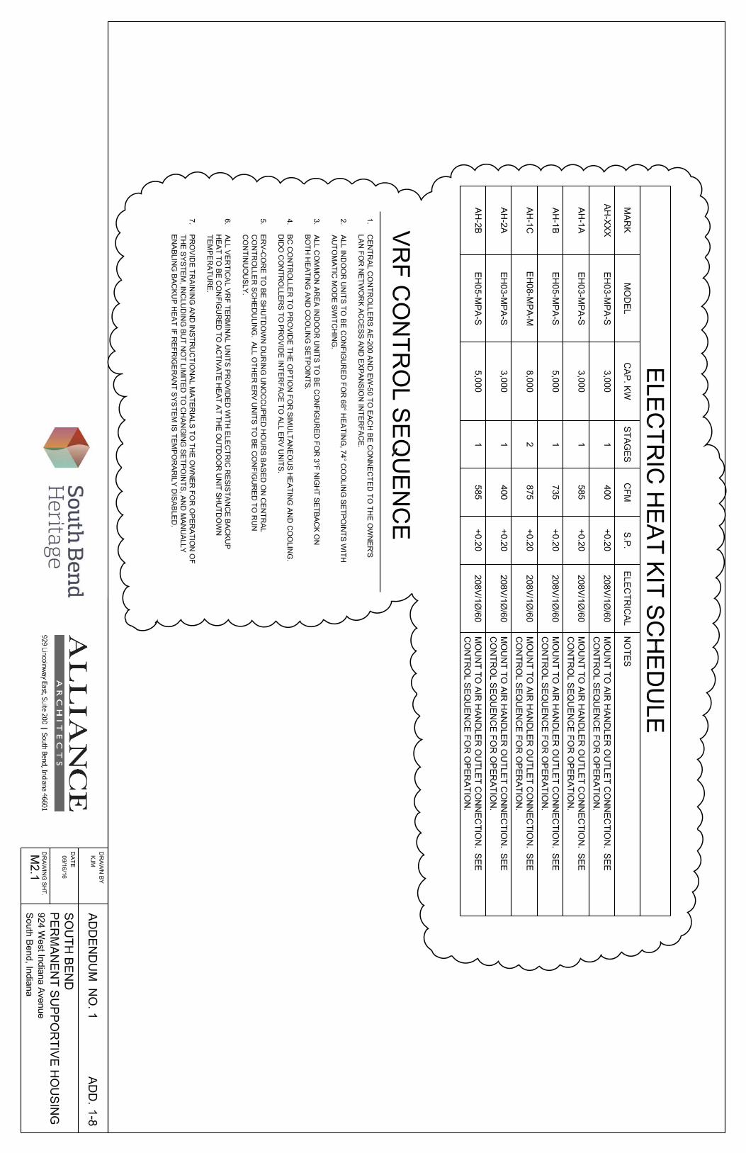
34. DRAWINGS; Sheet No. M2.1:
a. NOTES/OPTIONS:
1) Revise Note 7 to read, “INCLUDE LOW AMBIENT HOOD KIT WITH ASSOCIATEDWIND BAFFLES FOR 100% LOW AMBIENT COOLING DOWN TO -10 F.”

ADDENDUM NO. 1 -7- September 16, 2016
2) Revise Note 8 by adding the following: "IN ACCORDANCE WITH THE HEATACCESSORY SCHEDULE". (See attached Exhibit ADD 1-8.)
3) Add Note 9 as follows:
9. PROVIDE RELAY KIT FOR INTERLOCK WITH RADIANT HEAT INSAME SPACE.
b. VRF INDOOR UNIT SCHEDULE:
1) Add note reference 8 to all “VERTICAL TYPE” indoor units.
2) Add note reference 9 to Tags AH-1F and AH-1H.
c. VRF CONTROL SEQUENCE; Notes have been added. See attached Exhibit ADD 1-8.
d. HEAT ACCESSORY SCHEDULE; has been added. See attached Exhibit ADD 1-8.
e. UNIT MECHANICAL/CORRIDOR SCHEMATIC; add the following notes:
ELECTRICAL CONTRACTOR TO INSTALL SUPPORT SYSTEMS SHOWN,INCLUDING LOW-VOLTAGE HOOKS AND UNISTRUT SUPPORT FOR APARTMENTFEEDER CABLES.
PLUMBING CONTRACTOR TO INSTALL SUPPORT SYSTEM FOR DOMESTICWATER AND HYDRONIC PIPING AT GROUND FLOOR CORRIDOR.
35. DRAWINGS; Sheet No. M2.2; HYDRONIC HEAT/DOMESTIC WATER SYSTEM SCHEMATICDIAGRAMS:
a. Revise unit heater callout at Hot Room to "UH2".
b. Revise two radiant heat zones to Corridor/Stair 1 and Corridor/Stair 3.
c. At cold water feed for boiler, indicate plumbing contractor to install cold water line up to andincluding the RPZ. HVAC contractor to install indirect water heaters, recirculating pump andassociated piping up to valves shown. Plumbing contractor is to install water service,including meter and RPZ, water softener, water softener line serving laundry boxes andboiler feed, and all domestic hot water, hot water return and domestic cold water pipingextending from the valves on house side of mixing valve and pump P5.
36. DRAWINGS; Sheet No. M2.3; add the following notes:
1. MECHANICAL CONTRACTOR TO PROVIDE ALL REQUIRED CONTROL WIRING.
2. COORDINATE THE WORK OF THE ELECTRICAL CONTRACTOR FOR THEIRINSTALLATION OF BOXES, CONDUIT AND SLEEVES TO ALLOW FORINSTALLATION OF CONTROL WIRING TO TEMPERATURE SENSOR,THERMOSTATS AND SYSTEM CONTROLLERS.
3. ELECTRICAL CONTRACTOR TO PROVIDE POWER TO INDOOR AND OUTDOORUNITS AS SHOWN ON ELECTRICAL POWER PLANS.

ADDENDUM NO. 1 -8- September 16, 2016
37. DRAWINGS; Sheet No. MP1.0:
a. ONE-BEDROOM UNIT PLUMBING PLAN and ONE-BEDROOM ACCESSIBLE UNITPLUMBING PLAN:
1) Revise waste stack and sanitary line from kitchen sink to 2½" diameter in lieu of 2"diameter.
2) Add note at end units which reads, "WASTE STACK VENT TO BE 2" DIAMETER".
3) Delete reference to disposal at kitchen sink
b. PLUMBING FIXTURE SCHEDULE:
1) Add roof drain (RD), Jay R. Smith Manufacturing Company, Model No. 1005 withunder-deck clamp, 4" diameter.
2) In the Comments, add "SEE DETAIL 1/A2.1".
3) Add over flow (OF), same manufacturer as roof drain. Model No. 1005-WD2 withunder-deck clamp (Comment: "SEE DETAIL 1/A2.1").
4) Delete disposal.
5) At SH-1, install one additional layer of floor sheathing below unit in lieu of gypsumconcrete. Delete reference to slab recess. Revise model number to LES6333A75B.
6) SH-2 has been added (part of alternate). Best Bath 5LDS6030FBE75B barrier-free,low threshold shower with offset drain. Shower trim and shower transfer valve tomatch SH-1. Under REMARKS, add “PROVIDE WEIGHTED SHOWER CURTAIN,RUBBER THRESHOLD WATER STOP. SHOWER TO BE SET ON SLAB ATGROUND FLOOR AND ON ADDITIONAL LAYER OF FLOOR SHEATHING ATUPPER FLOOR. PROVIDE CHROME DROP ‘L’ AND TRANSFER VALVE AT CHASEEND OF UNIT.”
38. DRAWINGS; Sheet No. P1.1; GROUND FLOOR PLUMBING PLAN (revised drawing title from“GROUND FLOOR MECHANICAL PLAN”):
a. Revise callout for drain leading from unit mechanical rooms to the building drain to be a 2"diameter (typ.).
b. Add callout at drains leading from unit toilet rooms to 3" diameter (typ.).
c. Revise drains leading from back-to-back kitchen sinks to 2½" diameter (typ.).
d. Delete drain extending from sump pit and elevator pit to building drain.
e. Add callout for 1¼” vent up from Sink 4 in Healthcare 108 and from EWC. Add callout forEWC at graphics for fixture. Extend 1½” diameter vent to unit vent above.
f. Add to note, “2" IRRIGATION PIPE TO EXTERIOR. GALVANIZED STEEL TO EXTEND TOTHE EXTERIOR ABOVE THE FLOOR LINE.”
39. DRAWINGS; Sheet No. P1.2; UPPER FLOOR PLUMBING PLAN; at unit sink vent piping (shown atUnits 216 and 217), revise note to read, “2" VENT UP TO 3" VTR”.

ADDENDUM NO. 1 -9- September 16, 2016
40. DRAWINGS; Sheet No. P2.1; PLUMBING RISER DIAGRAM; has been added (see attachedAddendum Exhibits ADD 1-9 and ADD 1-10).
41. DRAWINGS; Sheet No. E1.1:
a. ELECTRICAL POWER GENERAL NOTES; add Notes as follows:
12. ELECTRICAL CONTRACTOR TO PROVIDE BOX AND LOW-VOLTAGEPATHWAY TO ABOVE CEILING AT TEMPERATURE SENSORS AND HVACSYSTEM CONTROLLER LOCATIONS AND THERMOSTAT LOCATIONS. COORDINATE EXACT LOCATION AND ROUTING WITH MECHANICALCONTRACTOR.
13. WIRING IN UNITS MAY BE ROMEX NON-METALLIC, SHEATHED CABLE. CIRCUITS SERVING MECHANICAL EQUIPMENT IN LIGHTING INCOMMON AREAS MAY BE MC CABLE OR IN CONDUIT. ALL OTHERCOMMON AREA ELECTRICAL WIRING SHALL BE IN CONDUIT.
14. APARTMENT FEEDER FROM MAIN SWITCHGEAR SHALL BE NON-METALLIC, SHEATHED CABLE.
b. GROUND FLOOR POWER PLAN:
1) At Manager’s Office, indicate HVAC system main controller. At Maintenance Office,add indication for HVAC system sub-controller.
2) Install 1½” PVC conduit from Utility 101 to the exterior for sprinkler system controlwires.
42. DRAWINGS; Sheet No. E1.2; UPPER FLOOR POWER PLAN; at Telecom Room, add indications fortelephone panel, quad-plex outlet and duplex outlet as shown on ground floor. At HousekeepingRoom 222, add one duplex GFI outlet.
43. DRAWINGS; Sheet No. E2.1; GROUND FLOOR LIGHTING PLAN; delete emergency light symbolat ST-2 (item is duplicated on UPPER FLOOR PLAN).
44. DRAWINGS; Sheet No. E3.1:
a. ONE-BEDROOM UNIT ELECTRICAL PLAN; delete reference to disposal, including garbagedisposal outlet below sink and switch.
b. ONE-BEDROOM H/C UNIT ELECTRICAL PLAN; delete disposal, switch and garbagedisposal outlet in cabinet.
c. ONE-BEDROOM SI UNIT ELECTRICAL PLAN; delete disposal, switch and garbage disposaloutlet in cabinet.
d. TYPICAL APARTMENT OUTLET PANEL; has been revised. See attached Exhibit ADD 1-11.
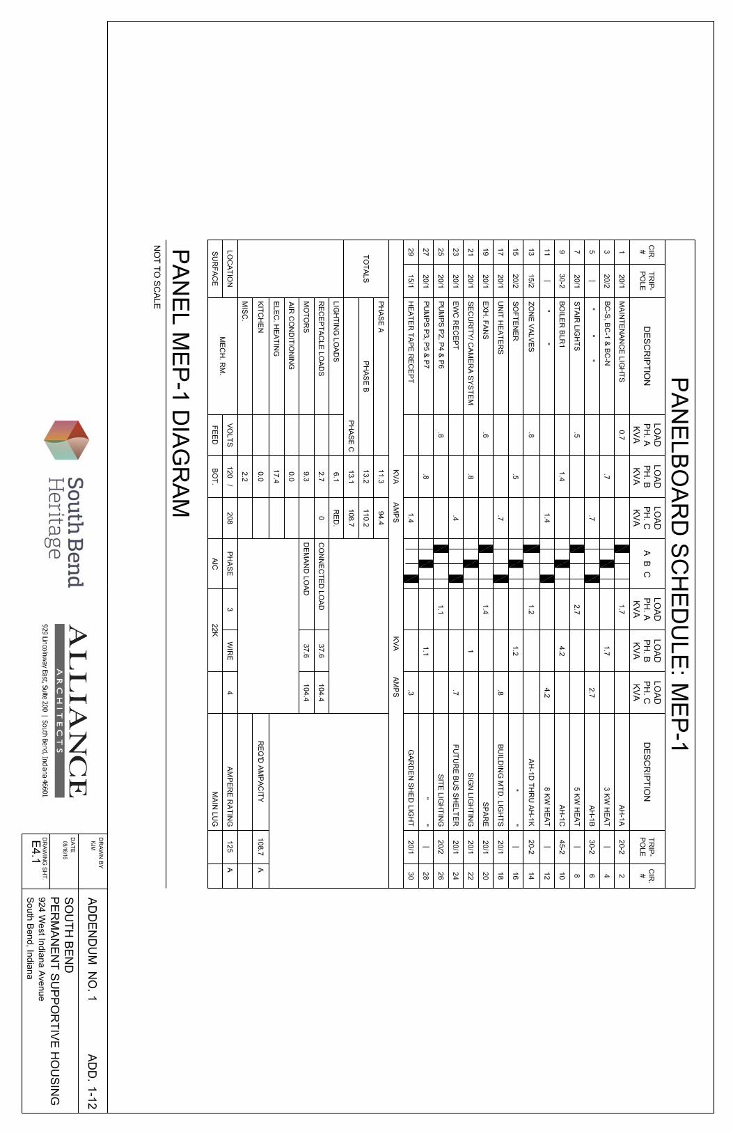
45. DRAWINGS; Sheet No. E4.1; add PANELBOARD SCHEDULE MEP-1 (see attached ExhibitADD 1-12).
46. DRAWINGS; Sheet No. E4.2:
a. Add ELECTRIC PANEL DIAGRAM LP-1, MEP-2 and MDP (see attached Exhibits ADD 1-14,ADD 1-15 and ADD 1-16).

ADDENDUM NO. 1 -10- September 16, 2016
b. ELECTRICAL RISER DIAGRAM; see revised portion on attached Exhibit ADD 1-13. Seeattached Exhibit ADD 1-17 for revised schedule of feeders, including revised service tablenotes below.
END OF ADDENDUM NO. 1
All bidders must acknowledge receipt of this Addendum in their bid.
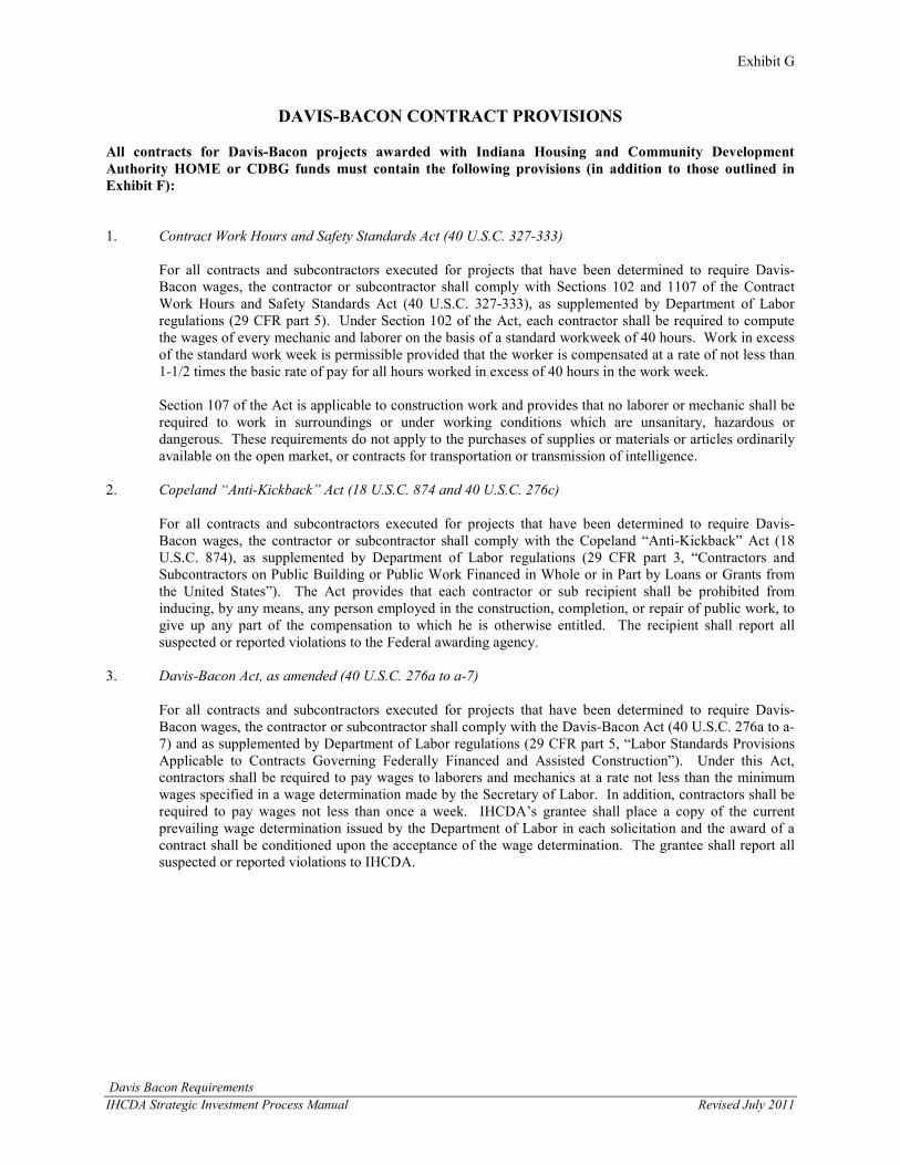
Exhibit G
Davis Bacon Requirements IHCDA Strategic Investment Process Manual Revised July 2011
DAVIS-BACON CONTRACT PROVISIONS
All contracts for Davis-Bacon projects awarded with Indiana Housing and Community Development Authority HOME or CDBG funds must contain the following provisions (in addition to those outlined in Exhibit F):
1. Contract Work Hours and Safety Standards Act (40 U.S.C. 327-333)
For all contracts and subcontractors executed for projects that have been determined to require Davis-Bacon wages, the contractor or subcontractor shall comply with Sections 102 and 1107 of the Contract Work Hours and Safety Standards Act (40 U.S.C. 327-333), as supplemented by Department of Labor regulations (29 CFR part 5). Under Section 102 of the Act, each contractor shall be required to compute the wages of every mechanic and laborer on the basis of a standard workweek of 40 hours. Work in excess of the standard work week is permissible provided that the worker is compensated at a rate of not less than 1-1/2 times the basic rate of pay for all hours worked in excess of 40 hours in the work week.
Section 107 of the Act is applicable to construction work and provides that no laborer or mechanic shall be required to work in surroundings or under working conditions which are unsanitary, hazardous or dangerous. These requirements do not apply to the purchases of supplies or materials or articles ordinarily available on the open market, or contracts for transportation or transmission of intelligence.
2. Copeland “Anti-Kickback” Act (18 U.S.C. 874 and 40 U.S.C. 276c)
For all contracts and subcontractors executed for projects that have been determined to require Davis-Bacon wages, the contractor or subcontractor shall comply with the Copeland “Anti-Kickback” Act (18 U.S.C. 874), as supplemented by Department of Labor regulations (29 CFR part 3, “Contractors and Subcontractors on Public Building or Public Work Financed in Whole or in Part by Loans or Grants from the United States”). The Act provides that each contractor or sub recipient shall be prohibited from inducing, by any means, any person employed in the construction, completion, or repair of public work, to give up any part of the compensation to which he is otherwise entitled. The recipient shall report all suspected or reported violations to the Federal awarding agency.
3. Davis-Bacon Act, as amended (40 U.S.C. 276a to a-7)
For all contracts and subcontractors executed for projects that have been determined to require Davis-Bacon wages, the contractor or subcontractor shall comply with the Davis-Bacon Act (40 U.S.C. 276a to a-7) and as supplemented by Department of Labor regulations (29 CFR part 5, “Labor Standards Provisions Applicable to Contracts Governing Federally Financed and Assisted Construction”). Under this Act, contractors shall be required to pay wages to laborers and mechanics at a rate not less than the minimum wages specified in a wage determination made by the Secretary of Labor. In addition, contractors shall be required to pay wages not less than once a week. IHCDA’s grantee shall place a copy of the current prevailing wage determination issued by the Department of Labor in each solicitation and the award of a contract shall be conditioned upon the acceptance of the wage determination. The grantee shall report all suspected or reported violations to IHCDA.

SOUTH BEND PERMANENT SUPPORTIVE HOUSING BID FORM 00 41 00 - 1
00 41 00 - BID FORM
Bidder’s Name:__________________________________________
Bidder’s Address: _______________________________________
The undersigned certifies that the submitted bid is based upon a careful examination of the applicable construction documents, and existing site conditions and is total and complete for the named portions of the work, and is in accordance with all Documents of Record to date of this Proposal.
BID PROPOSAL:
The following in a bonafide lump sum base bid proposal under for the work at: South Bend Permanent Supportive Housing
BID PACKAGE SUBDIVISION (BPS)
SUBDIVISION DESCRIPTION LUMP SUM
5 GYPSUM CONCRETE $
6 GENERAL TRADES I $
7 GENERAL TRADES II $
8 GYPSUM DRYWALL $
9 MASONRY $
10 METALS $
11 CASEWORK $
12 ROOFING $
13 INSULATION $
14 PREFORMED FIBER CEMENT CLADDING $
15 ALUMINUM DOORS AND STOREFRONT $
16 DOORS AND HARDWARE $
17 WINDOWS $
18 RESILIENT FLOORING $
19 CARPET $

SOUTH BEND PERMANENT SUPPORTIVE HOUSING BID FORM 00 41 00 - 2
20 PAINTING $
21 RESIDENTIAL APPLIANCES $
22 HYDRAULIC PASSENGER ELEVATOR $
23 FIRE SPRINKLER SYSTEM $
24 MECHANICAL $
25 ELECTRICAL $
26 SPECIAL SYSTEMS $
27 SITE IMPROVEMENTS $
28 LANDSCAPING $
29 IRRIGATION $
30 PLUMBING $
_____________________________________________________________________________________ (Dollars) (written amount)
ALTERNATES:
Alternate No. 1: (BPS-27) Delete Garden Area as detailed on Sheets C5.1 and C5.2 including Community Garden, Pavilion and Screen Walls.
ADD/DEDUCT _________________________________________$________________________
Alternate No. 2: (BPS-9) Delete North Patio and brick masonry retaining wall as detailed on Sheet C5.2. Continue brick along the base of the exterior wall.
ADD/DEDUCT _________________________________________$________________________
Alternate No. 3: (BPS-5,6,7,8,12,14,15,18,20,23) Delete two-story storefront circulation space located at the south end of Corridors 100, 200 and at the east end of Corridors 130, 230 in its entirety and change the location of Stairs ST-1 and ST-3 to provide for direct ingress/egress.
ADD/DEDUCT _________________________________________$________________________

SOUTH BEND PERMANENT SUPPORTIVE HOUSING BID FORM 00 41 00 - 3
Alternate No. 4: (BPS-14) Delete all exterior Fiber Cement Panel/Reveal Cladding as specified in Section 07 46 46 and illustrated on Sheets A3.1 and A3.2 and substitute fiber cement lap siding cladding.
ADD/DEDUCT _________________________________________$________________________
Alternate No. 5: (BPS-17) Delete Clad Windows as specified in Section 08 52 13 and substitute impact resistant exterior-grade rigid polyvinyl chloride (PVC) windows, equal to “Silver Line” by Anderson.
ADD/DEDUCT _________________________________________$________________________
Alternate No. 6: (BPS-18) Delete all sheet vinyl flooring (SVF) as specified in Section 09 65 00 and noted on Sheet A8.1 Room Finish Schedule and substitute vinyl composition tile (VCT) flooring.
ADD/DEDUCT _________________________________________$________________________
Alternate No. 7: (BPS-18) Delete vinyl plank (VP) flooring in Apartment Units as specified in Section 09 65 00 and noted on Sheet A8.1 Room Finish Schedule and substitute Mowhawk Group “Strong Step C0003” vinyl plank flooring.
ADD/DEDUCT _________________________________________$________________________
Alternate No. 8: (BPS-6,7,8,20) Delete soffits above Kitchen overhead cabinets in all Apartment Units and Community Room Kitchen-119. See Sheet A6.5, Detail 8.
ADD/DEDUCT _________________________________________$________________________
Alternate No. 9: (BPS-30) Delete all Apartment Unit single piece tub/shower units (T/SH1) and substitute shower enclosure (SH2).
ADD/DEDUCT _________________________________________$________________________
Alternate No. 10: (BPS-24) Delete snow melting loop, associated pumps P7 abd P8, and heat exchanger HXG1; Delete show melting control Tekmar 654 and sensor Tekmar 090.
ADD/DEDUCT _________________________________________$________________________
Alternate No. 11: (BPS-24) Delete radiant floors in Vestibules-105 and Stairs-ST1, ST3. Vestibule-105 to heat using the associated VRF terminal unit; Stair-ST1, ST3 to have 3’ baseboard installed on the partition wall in both the Stairs and Vestibule. Delete thermostatic mixing valve on the loop and connect output to boiler input BLR1-1 in lieu of BLR1-2.
ADD/DEDUCT _________________________________________$________________________

SOUTH BEND PERMANENT SUPPORTIVE HOUSING BID FORM 00 41 00 - 4
Alternate No. 12: (BPS-24) Delete in each Apartment Unit, the vertical ducted VRF unit. Provide two wall-mounted terminal units, one in the Living Room and one in the Bed Room. Both VRF units to be tied to the same lineset/BC controller port using a tee located in the Corridor outside the Apartment. Fresh air to be ducted to a single fresh air supply grille on the wall adjacent to the door at 7’aff. Provide centrol controller EW-50A to service additional units and connect to Owner’s LAN.
ADD/DEDUCT _________________________________________$________________________
Alternate No. 13: Reference Addendum Exhibit ADD 1-19 (attached). Revise stair enclosure configuration as shown. Eliminate storefront framing system and entry door. Revise exterior finishes as shown.
ADD/DEDUCT _________________________________________$________________________
VOLUNTARY ALTERNATES:
Bidders choice, selection, or option
Fully describe all proposed substitutions, changes or alternates of each type and description, stating appropriate ADD or DEDUCT amounts where applicable. Sufficient technical materials must accompany voluntary alternates in order for Architect to review and judge the merits of the proposed voluntary alternates. (None below shall be included in Base Bid).
_______________________________________________________________________________________
_______________________________________________________________________________________
_______________________________________________________________________________________
_______________________________________________________________________________________
_______________________________________________________________________________________
_______________________________________________________________________________________ (Attach additional information to this form if needed).
BID QUALIFICATIONS:
"DO NOT USE THIS SECTION FOR THE SUBMISSION OF VOLUNTARY ALTERNATES OR MATERIAL SUBSTITUTIONS. USE FOR EITHER OF THE ABOVE WILL RESULT IN DISQUALIFICATION OF BID AT OWNER'S DISCRETION."
The items listed in this bid form are subject to the following qualifications (bidder to clarify or qualify any point in question on the plans or specifications). Failure to do so binds the Bidder to the precise work as listed in these specifications and on the drawings.
________________________________________________________________________________________
________________________________________________________________________________________

SOUTH BEND PERMANENT SUPPORTIVE HOUSING BID FORM 00 41 00 - 5
________________________________________________________________________________________
ADDENDA:
The following addenda have been received, are hereby acknowledged, and their execution is included in the above proposal amount:
Addendum No. _________ Dated _____________ Addendum No. _________ Dated _____________
Addendum No. _________ Dated _____________ Addendum No. _________ Dated _____________
Addendum No. _________ Dated _____________ Addendum No. _________ Dated _____________
In submitting this bid it is understood that the right is reserved by the Owner to reject any and all bids, and it is agreed that this bid may not be withdrawn for a period of sixty (60) days after opening and recording of bids. Bids may be withdrawn at any time prior to scheduled time for opening of bids or any authorized postponement thereof.
Having carefully examined the information for bidders, the specifications, Conditions of the Contract, the project manual, and all other related contract documents including those incorporated by reference and all addenda thereto; and having personally visited the actual site location, the undersigned has satisfied himself as to all the quantities and conditions and understands that in signing this proposal, he waives all right to plead any misunderstanding regarding same. Finally, the undersigned proposes to furnish all material, labor, tools, equipment, permits, certificates, etc. as necessary or incidental to this Bid Proposal in accordance with the said documents and to provide continuous housekeeping/clean-up and final clean-up.
CONSTRUCTION DURATION
The following work durations are proposed for the above referenced Bid Package.
Submittal _____________________________________________work days __________________
Delivery _____________________________________________work days __________________
Installation ___________________________________________work days __________________
Overall _____________________________________________work days __________________
COMPLETENESS:
The bid is inclusive and complete, representing all applicable work required for completion of the noted divisions and/or sections. The Bid is to include all of the required labor, material, and related expenses.
I hereby acknowledge that I have read and understand pages 1 through 3 constituting all of the Bid Form for the Permanent Supportive Housing.
______________________________________________________________________________________(Signature of Bidder or Authorized Officer)

SOUTH BEND PERMANENT SUPPORTIVE HOUSING BID FORM 00 41 00 - 6
Name of Bidder: _______________________________________________________________________
_______________________________________________________________________
Address: _______________________________________________________________________ ________________________________________________________________________
Date: _______________________________________Phone: ____________________________
Attest: _______________________________________Date: ____________________________
Please check below if this Contractor is categorized as:
A Disadvantaged Business Enterprise _______Yes _______No
A Women Business Enterprise _______Yes _______No ______
A Minority Business Enterprise _______Yes _______No ______
___________________________________________________________________________________ Signature
___________________________________________________________________________________ Title
END OF SECTION

SOUTH BEND PERMANENT SUPPORTIVE HOUSING SCOPE OF WORK 00 90 00 - 1
00 90 00 - SCOPE OF WORK
A. GENERAL
1. RELATED DOCUMENTS
a. Refer to Section 01 81 13 - NATIONAL GREEN BUILDING STANDARD DESIGN REQUIREMENTS
b. Refer to Section 01 11 01 SUMMARY OF WORK for South Bend Permanent Supportive Housing, all in accordance with plans and specifications prepared by Alliance Architects.
2. SCOPE
a. The Project consists of the total construction and complete finishing of a thirty-two (32) unit, two-story, 35,700 square feet +/- permanent supportive housing project located at 924 West Indiana Avenue, South Bend, Indiana, all to be as shown on the plans and/or herein specified. The requirements set forth in Division I shall apply to all contractors and/or subcontractors.
b. Each contactor is responsible to familiarize themselves with the entire contents of the Construction Documents and their respective bid packages. Specifications and Drawings listed under each bid package are for reference and may not include every aspect of the bid package.
3. WORK COVERED BY CONTRACT DOCUMENTS
a. BID PACKAGE 5 – GYPSUM CONCRETE: 1. Placement of all gypsum concrete floor underlayment on the Upper floor.
b. BID PACKAGE 6 – GENERAL TRADES 1: 1. Construction of wood framed walls, floors and roof trusses, including
shear transfer anchors and hold-downs. 2. Construction of exterior walls and installation of insulated sheathing. 3. Construction of wood framed stairs. 4. Installation of all structural steel. 5. Installation of all exterior wall windows. 6. Installation of temporary enclosures and protection. 7. Provide and install all firestopping and joint sealants. 8. Provide and install of all wood blocking. 9. Construction of all wood decking.
c. BID PACKAGE 7 – GENERAL TRADES II: 1. Provide all finish carpentry. 2. Installation of all doors/frames, access doors, door hardware. 3. Provide and install acoustical ceiling systems. 4. Installation of casework. 5. Installation of all toilet room, bathroom accessories. 6. Provide and install joint sealants (interior only). 7. Installation of steel stair railings. 8. Provide and install postal specialties. 9. Provide and install roof access hatch and ladder.

SOUTH BEND PERMANENT SUPPORTIVE HOUSING SCOPE OF WORK 00 90 00 - 2
10. Provide and install fire extinguishers, fire extinguisher cabinets and brackets.
11. Provide and install all corner guards.
d. BID PACKAGE 8 – GYPSUM DRYWALL: 1. Provide and install gypsum wallboard systems.
e. BID PACKAGE 9 – MASONRY: 1. Provide and install brick and stone masonry.
f. BID PACKAGE 10 – METALS 1. Provide all structural steel, miscellaneous metals and stair railings. 2. Installation by others.
g. BID PACKAGE 11 – CASEWORK: 1. Provide all pre-manufactured casework. 2. Installation by others.
h. BID PACKAGE 12 – ROOFING: 1. Provide and install thermoplastic polyolefin roofing system. 2. Provide and install roof flashing and pre-finished trim, including coping. 3. Provide and install all roof accessories. 4. Provide and install metal roof system.
i. BID PACKAGE 13 – INSULATION: 1. Provide and install all building loose insulation or batt insulation,
including interior walls, ceilings, building overhangs and attic. 2. Provide and install spray applied insulation.
j. BID PACKAGE 14 – PREFORMED FIBER CEMENT CLADDING: 1. Provide and install all preformed fiber cement exterior cladding systems
and trim. 2. Provide and install all pre-finished metal siding and louvers. 3. Provide and install all soffit materials. 4. Install all flashing and perimeter sealant.
k. BID PACKAGE 15 – ALUMINUM DOORS AND STOREFRONT: 1. Provide and install all aluminum doors and storefront systems including
all glass and glazing.
l. BID PACKAGE 16 – DOORS AND HARDWARE: 1. Provide all steel doors/frames. 2. Provide all steel-framed borrowed lites, including all glazing. 3. Provide all wood doors/frames, including all glazing. 4. Provide all access panels. 5. Provide all door hardware. 6. Installation by others.
m. BID PACKAGE 17 – WINDOWS: 1. Provide all clad window units. 2. Installation by others.
SOUTH BEND PERMANENT SUPPORTIVE HOUSING SCOPE OF WORK 00 90 00 - 3
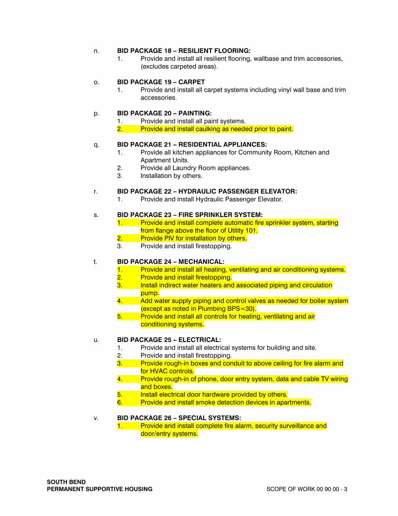
n. BID PACKAGE 18 – RESILIENT FLOORING: 1. Provide and install all resilient flooring, wallbase and trim accessories,
(excludes carpeted areas).
o. BID PACKAGE 19 – CARPET 1. Provide and install all carpet systems including vinyl wall base and trim
accessories.
p. BID PACKAGE 20 – PAINTING: 1. Provide and install all paint systems. 2. Provide and install caulking as needed prior to paint.
q. BID PACKAGE 21 – RESIDENTIAL APPLIANCES: 1. Provide all kitchen appliances for Community Room, Kitchen and
Apartment Units. 2. Provide all Laundry Room appliances. 3. Installation by others.
r. BID PACKAGE 22 – HYDRAULIC PASSENGER ELEVATOR: 1. Provide and install Hydraulic Passenger Elevator.
s. BID PACKAGE 23 – FIRE SPRINKLER SYSTEM: 1. Provide and install complete automatic fire sprinkler system, starting
from flange above the floor of Utility 101. 2. Provide PIV for installation by others. 3. Provide and install firestopping.
t. BID PACKAGE 24 – MECHANICAL: 1. Provide and install all heating, ventilating and air conditioning systems. 2. Provide and install firestopping. 3. Install indirect water heaters and associated piping and circulation
pump. 4. Add water supply piping and control valves as needed for boiler system
(except as noted in Plumbing BPS=30). 5. Provide and install all controls for heating, ventilating and air
conditioning systems.
u. BID PACKAGE 25 – ELECTRICAL: 1. Provide and install all electrical systems for building and site. 2. Provide and install firestopping. 3. Provide rough-in boxes and conduit to above ceiling for fire alarm and
for HVAC controls. 4. Provide rough-in of phone, door entry system, data and cable TV wiring
and boxes. 5. Install electrical door hardware provided by others. 6. Provide and install smoke detection devices in apartments.
v. BID PACKAGE 26 – SPECIAL SYSTEMS: 1. Provide and install complete fire alarm, security surveillance and
door/entry systems.

SOUTH BEND PERMANENT SUPPORTIVE HOUSING SCOPE OF WORK 00 90 00 - 4
w. BID PACKAGE 27 – SITE IMPROVEMENTS: 1. Construction of Garden Area, per Detail 1/C5.1. Work includes concrete
pads and walks, garden plots, fencing and gates, Garden Pavilion/Shed, grill, picnic table, rain barrel, stone paths and other miscellaneous work as shown.
2. Provide and install flagpole, per Detail 2/C5.1 3. Provide and install bike racks. 4. Construct trash enclosure screen walls, gates and bollards, per Details
3,4 & 5 /C5.1 5. Extension of storm drain piping from roof building roof drains to storm
sewer system, including clean out. 6. Extension of storm drain piping from porch roofs to rain gardens. 7. Construction of concrete site light bases per Detail 7/C5.1 including
coordination with Electrical Contractor.
x. BID PACKAGE 28 – LANDSCAPING: 1. Provide and install plant materials. 2. Provide and install lawns, including all open lawns, no-mow lawns and
native habitat areas 3. Construction and planting of rain gardens. 4. Provide and install soil mixture for garden plots.
y. BID PACKAGE 29 – IRRIGATION 1. Installation of irrigation system.
z. BID PACKAGE 30 – PLUMBING 1. Provide and install plumbing systems from stub 5’ outside of building,
including domestic water, fire service water supply to Utility 101 (including PIV provided by others), sanitary, sewer and gas.
2. Provide and install water line to garden area. 3. Install water connection to refrigerators in Community Room and water
and gas connections to Laundry Room equipment.
aa. All work for the complete construction of this project will be under multiple prime contracts with the South Bend Heritage Construction Manager/GC.
bb. Each contractor is responsible for their own cutting and patching where necessary. This includes the use of trades required for the specific patching requirements.
4. PRIME CONTRACTS
a. The multiple prime contracts are defined by Bid Packages which designate one or more various disciplines of work. These Bid Packages are being packaged to maintain job scheduling. Due to this fast track method, time is of the essence in performance of this work.
b. A construction progress schedule, which defines milestone progress for this project, will be issued with each Contract. This schedule will be preliminary and is meant to define the project goals. A more detailed schedule will be developed after contracts are awarded.
c. The Bid Package Subdivisions (BPS) being considered under this Bid Package are as follows:

SOUTH BEND PERMANENT SUPPORTIVE HOUSING SCOPE OF WORK 00 90 00 - 5
a) BPS Description
5 GYPSUM CONCRETE 6 GENERAL TRADES I 7 GENERAL TRADES II 8 GYPSUM WALLBOARD 9 MASONRY
10 METALS 11 CASEWORK 12 ROOFING 13 INSULATION 14 PREFORMED FIBER CEMENT CLADDING 15 ALUMINUM DOORS AND STOREFONTS 16 DOORS AND HARDWARE 17 WINDOWS 18 RESILIENT FLOORING 19 CARPET 20 PAINTING 21 RESIDENTIAL APPLIANCES 22 HYDRAULIC PASSENGER ELEVATOR 23 FIRE SPRINKLER SYSTEM 24 MECHANICAL 25 ELECTRICAL 26 SPECIAL SYSTEMS 27 SITE IMPROVEMENTS 28 LANDSCAPING 29 IRRIGATION 30 PLUMBING
d. Future Bid Packages will be added under subsequent phases of construction documents, which will, in total, define the overall scope of this project.
5. OWNER REQUIREMENTS AND USE OF PREMISES
a. It is the intention of the Owner to award contracts to the successful Bid Package Sub-Division Contractors who submit the lowest and/or best bid. Any bidder, at his/her option may submit a combined bid made from any combination of individual bid package sub-divisions. A separate bid must be submitted for each bid package sub-division and applicable alternates in addition to the combined bid. Combined bids will not be considered unless the bidder also submits separate bids on each bid package sub-division and alternates contained in the combined bid. Voluntary alternates will be considered provided the bidder first submits a bid based on specified work.
b. Abusive language, music radios, actions or disrespectful behavior by any workers directed to Construction Manager/GC’s employees, visitors, or others while working on the project grounds is subject to immediate removal and dismissal.
c. Designated smoking areas, parking areas, and construction trailer staging areas will be as directed by the Construction Manager/GC. No parking or loitering will be permitted on access roads or mobilization areas. Fire lanes shall be kept clear at all times to maintain access to the existing buildings and fire department connections.

SOUTH BEND PERMANENT SUPPORTIVE HOUSING SCOPE OF WORK 00 90 00 - 6
c. No materials may be stored within the building. Contractors shall be responsible for scheduling on time delivery of their materials or provide their own storage trailers on site, located as directed by the Construction Manager/GC.
6. LICENSE REQUIREMENTS
a. All contractors shall be licensed as required by Local and State agencies. Contractors shall verify these requirements with the respective governing agencies.
B. PRODUCTS (Not used)
C. BID PACKAGE SUBDIVISION DESCRIPTION
1. All products listed will be furnished and installed unless otherwise noted. All Contractors shall be responsible for layout for their scope of work.
a. BPS Number BID PACKAGE SUB-DIVISION DESCRIPTION
5. GYPSUM CONCRETE
Specifications: Included: General Requirements, Division 0 and 1 03 50 50 Gypsum Concrete
Drawings: S2.1 A1.2 A4.1 A4.2 A4.3 A4.4
6. GENERAL TRADES I
Specifications: Included: General Requirements, Division 0 and 1
05 12 00 Structural Steel 05 50 00 Miscellaneous Metals 06 02 00 Temporary Enclosures 06 10 00 Rough Carpentry 06 19 02 Pre-fabricated Wood Trusses 07 84 00 Firestopping 07 92 00 Joint Sealants 08 52 13 Clad Wood Windows
Drawings: S1.1 S1.2 S2.1 S2.2 A1.1- A2.2 A4.1-A5.2

SOUTH BEND PERMANENT SUPPORTIVE HOUSING SCOPE OF WORK 00 90 00 - 7
A6.5-A6.6
7. GENERAL TRADES II
Specifications: Included: General Requirements, Division 0 and 1
05 51 00 Metal Handrails 06 02 00 Temporary Enclosure 06 20 00 Finish Carpentry 07 92 00 Joint Sealants 08 11 13 Hollow Metal Doors and Frames 08 14 00 Wood Doors 08 31 00 Access Panels 08 71 00 Finish Hardware 08 81 00 Glass and Glazing 10 26 13 Corner Guards 10 44 16 Fire Extinguisher and Cabinets 10 55 00 Postal Specialties 11 82 00 Rubbish Chutes 12 35 30 Casework 12 35 35 Casework - Apartments
Drawings: S1.1- S1.2 S2.2 A1.1- A9.2
8. GYPSUM WALLBOARD SYSTEM
Specifications: Included: General Requirements, Division 0 and 1
09 21 16 Gypsum Board
Drawings: A1.1- A9.2
9. MASONRY
Specifications: Included: General Requirements, Division 0 and 1
04 21 31 Brick Unit Masonry 04 72 00 Architectural Cast Stone
Drawings: S1.1-S1.2 A1.1-A1.2 A3.1-A3.2 A4.1-A4.2

SOUTH BEND PERMANENT SUPPORTIVE HOUSING SCOPE OF WORK 00 90 00 - 8
10. METALS
Specifications: Included: General Requirements, Division 0 and 1
05 12 00 Structural Steel 05 50 00 Miscellaneous Metals 05 51 00 Metal Handrails
Drawings: S1.1-S1.2 S2.1-S2.2 A2.1 A5.1-A5.2
11. CASEWORK
Specifications: Included: General Requirements, Division 0 and 1
12 35 30 Casework
Drawings: A1.1-A1.2 A6.1-A6.6
12. ROOFING
Specifications: Included: General Requirements, Division 0 and 1
07 41 13 Metal Roof Panels 07 50 00 General Roofing 07 54 23 TPO Roofing 07 60 00 Flashing and Sheet Metal
Drawings: A2.1- A4.4
13. INSULATION
Specifications: Included: General Requirements, Division 0 and 1
07 21 00 Building Insulation
Drawings: A.1.1-A7.1

SOUTH BEND PERMANENT SUPPORTIVE HOUSING SCOPE OF WORK 00 90 00 - 9
14. PREFORMED FIBER CEMENT CLADDING
Specifications: Included: General Requirements, Division 0 and 1
07 46 46 Fiber Cement Cladding 07 60 00 Flashing and Sheet Metal 07 92 00 Joist Sealants (Window and Door Perimeters and at Material Junctures throughout the Building Exterior)
Drawings: A1.1-A4.4
15. ALUMINUM DOORS AND STOREFRONT
Specifications: Included: General Requirements, Division 0 and 1
08 40 00 Aluminum Doors 08 41 13 Aluminum Storefront Framing and Windows
Drawings: A1.1-A1.2 A3.1-A3.2 A7.2
16. DOORS AND HARDWARE
Specifications: Included: General Requirements, Division 0 and 1
08 11 13 Hollow Metal Doors and Frames and Borrowed Lites 08 14 00 Wood Doors 08 71 00 Finish Hardware 08 81 00 Glass and Glazing
Drawings: A1.1-A1.2 A7.1
17. WINDOWS
Specifications: Included: General Requirements, Division 0 and 1
08 52 13 Clad Wood Windows 08 81 00 Glass and Glazing
Drawings: A1.1-A1.2 A3.1-A4.4 A7.2

SOUTH BEND PERMANENT SUPPORTIVE HOUSING SCOPE OF WORK 00 90 00 - 10
18. RESILIENT FLOORING
Specifications: Included: General Requirements, Division 0 and 1
09 65 00 Resilient Flooring
Drawings: A1.1-A1.2 A6.5 A8.1
19. CARPET
Specifications: Included: General Requirements, Division 0 and 1
09 68 00 Carpet
Drawings: A1.1-A1.2 A8.1
20. PAINTING
Specifications: Included: General Requirements, Division 0 and 1
07 92 00 Joint Sealants 09 91 00 Painting
Drawings: A1.1-A1.2 A8.1
21. RESIDENTIAL APPLIANCES
Specifications: Included: General Requirements, Division 0 and 1
11 30 00 Residential Equipment
Drawings: A1.1-A1.2 A6.1-A6.5
22. HYDRAULIC PASSENGER ELEVATOR
Specifications: Included: General Requirements, Division 0 and 1
14 24 00 Hydraulic Passenger Elevator

SOUTH BEND PERMANENT SUPPORTIVE HOUSING SCOPE OF WORK 00 90 00 - 11
Drawings: A.1.1-A1.2 A5.1 E1.1
23. FIRE SPRINKLER SYSTEM
Specifications: Included: General Requirements, Division 0 and 1
21 02 00 Fire Protection 07 84 00 Firestopping
Drawings: C4.0-C4.2 P1.1 E1.1
24. MECHANICAL
Specifications: Included: General Requirements, Division 0 and 1
07 84 00 Firestopping 11 30 00 Residential Equipment (Range Hood Installation) Division 23 HEATING, VENTILATING AND AIR CONDITIONING
Drawings: C4.0-C4.2 M1.1-M1.2
M2.1 M2.2 HYDRONIC HEAT/DOMESTIC WATER SYSTEM SCHEMATIC
DIAGRAMS (Mechanical contractor to install all items shown except for those items identified in the Plumbing bid package.)
M2.3 MP1.1 E1.1-E4.2
25. ELECTRICAL
Specifications: Included: General Requirements, Division 0 and 1
07 84 00 Firestopping 08 71 00 Finish Hardware (Electrical Items Only) 11 30 00 Residential Equipment (Range Hood Electrical Only) Division 26 ELECTRICAL 27 10 00 Structured Communication Wiring 27 41 00 Television System 28 46 11 Smoke Detection

SOUTH BEND PERMANENT SUPPORTIVE HOUSING SCOPE OF WORK 00 90 00 - 12
Drawings: C4.0-C4.2 M2.3 (All plumbing work not performed by mechanical contractor) E1.1-E4.2
26. SPECIAL SYSTEMS
Specifications: Included: General Requirements, Division 0 and 1
07 84 00 Firestopping 28 15 23 Entry/Intercom System 28 23 00 Security/Surveillance System 28 46 00 Fire Alarm System
Drawings: E1.1-E4.2
27. SITE IMPROVEMENTS
Specifications: Included: General Requirements, Division 0 and 1
02630 Storm Utility Drainage 02751 Concrete Paving
Drawings: C4.2 C5.1-C5.2
28. LANDSCAPING
Specifications: Included: General Requirements, Division 0 and 1
32 92 00 Lawns 32 93 00 Plants
Drawings: C4.2 L1.0
29. IRRIGATION
Specifications: Included: General Requirements, Division 0 and 1
32 84 00 Irrigation Systems
Drawings: L2.0

SOUTH BEND PERMANENT SUPPORTIVE HOUSING SCOPE OF WORK 00 90 00 - 13
30. PLUMBING
Specifications: Included: General Requirements, Division 0 and 1
07 84 00 Firestopping Division 22 PLUMBING
Drawings: C4.0-C4.2 M2.1 M2.2 HYDRONIC HEAT/DOMESTIC WATER SYSTEM SCHEMATIC
DIAGRAMS (See Addendum description for plumbing scope of work.)
MP1.1 P1.1 P1.2
END OF SECTION

08 81 00 - GLAZING
A. Scope
This section includes furnishing all labor and materials for glass and glazing as shown on the drawings and/oras required for the work specified.
1. Job Requirements: Obtain sizes for all glass from actual frames and sash. The Contractor shallassume the responsibility for correct sizes.
All glass shall be new and the best grades of its respective kinds and shall be free from flaws. Nosecondhand glass will be acceptable. Each light shall bear the manufacturer's label and be deliveredin labeled boxes.
2. Related Documents: The provisions of the General Conditions, Supplementary Conditions, and theSections included under Division 1, General Requirements, are included as a part of this Section asthough bound herein.
3. Glass and Glazing Specified Elsewhere:
a. Section 08 40 00 - ALUMINUM DOORS.b. Section 08 41 13 - ALUMINUM STOREFRONT FRAMING AND WINDOWS.c. Section 08 52 13 - CLAD WOOD WINDOWS.
4. System Performance Requirements:
a. General: Provide glazing systems that are produced, fabricated, and installed to withstandnormal thermal movement, wind loading, and impact loading (where applicable), withoutfailure including loss or glass breakage attributable to the following: defective manufacturer,fabrication, and installation; failure of sealants or gaskets to remain watertight and airtight;deterioration of glazing materials; and other defects in construction.
b. Glass Design: Glass thicknesses as indicated are for detailing only. Confirm glassthicknesses by analyzing Project loads and in service conditions. Provide glass lights for thevarious size openings in the thicknesses and strengths (annealed or heat-treated) to meetor exceed the following criteria: 1) Minimum glass thickness, nominally, of lights in exterior walls is 1/8".
c. Specific Hazardous Locations: The following shall be considered specific hazardouslocations for purposes of glazing.1) Glazing in ingress and means of egress doors.2) Glazing adjacent to a door and within the same wall plane as the door whose
nearest vertical edge is within 24" of the door in a closed position and whose bottomedge is less than 60" above the floor or walking surface, unless an interveninginterior permanent wall is between the door and the glazing.
3) Glazing in fixed panels having a glazed area in excess of 9 square feet with thelowest edge less than 18" above the finish floor level or walking surface within 36"of such glazing, unless a horizontal member not less than 1-1/2" in width is locatedbetween 24" and 36" above the walking surface.
d. Normal thermal movement results form the following maximum change (range) in ambientand surface temperatures acting on glass framing members and glazing components. Baseengineering calculation on materials' actual surface temperatures due to both solar heat gainand nighttime sky heat loss.1) Temperature Change (Range): 120F, ambient; 180F, material surfaces.
SOUTH BENDPERMANENT SUPPORTIVE HOUSING GLAZING 08 81 00-1

08 81 00-2
5. Submittals:
a. Product Data: Submit manufacturer's technical data for each glass type and glazing materialrequired, including installation and maintenance instructions.
b. Samples for Verification Purposes: Shall be 12" square samples of each type of glassindicated except for clear monolithic glass products, and 12" long samples of each colorrequired for each type of sealant or gasket exposed to view. Install sealant or gasket samplebetween two strips of material representative in color of the adjoining framing system.
6. Quality Assurance:
a. Comply with applicable codes and regulations and with the Consumer Product SafetyCommission CPSC 16 CFR 1201 and with applicable recommendations of Flat GlassMarketing Association (FGMA) "Glazing Manual."
b. Provide labels showing glass manufacturer's identity, type of glass, thickness, and quality.Labels shall remain on glass until it has been set and approved by the Architect.
c. Insulating glass units shall be provided with a 10 year warranty covering material obstructionof vision as a result of dust or film formation on the internal glass surfaces caused by failureof the hermetic seal, other than through glass breakage.
7. Delivery, Storage, and Handling: Deliver glass to site in suitable containers that will protect glassfrom the weather and from breakage. Carefully store material, as directed, in a safe place wherebreakage can be reduced to a minimum. Deliver sufficient glass to allow for normal breakage.Glazing compounds shall arrive at the project site in labeled containers which have not been opened.
8. Project Conditions:
a. Environmental Conditions: Do not proceed with glazing when ambient and substratetemperature conditions are outside the limits permitted by glazing materials manufactureror when glazing channel substrates are wet from rain, frost, condensation, or other causes.1) Install liquid sealants at ambient and substrate temperatures above 40.
9. Warranty:
a. General: Warranties specified in this Article shall not deprive the Owner of other rights theOwner may have under other provisions of the Contract Documents and will be in additionto and run concurrent with other warranties made by the Contractor under requirements ofthe Contract Documents.
b. Manufacturer's Warranty on Insulating Glass: Submit written warranty signed bymanufacturer of insulating glass agreeing to furnish replacements for insulating glass unitsthat deteriorate, f.o.b. point of manufacturer, freight allowed to project site, within specifiedwarranty period indicated below. Warranty covers only deterioration due to normalconditions of use and not to handling, installing, protecting, and maintaining practicescontrary to glass manufacturer's published instructions.1) Warranty Period: Manufacturer's standard but not less than 10 years after date of
Substantial Completion.
SOUTH BENDPERMANENT SUPPORTIVE HOUSING GLAZING 08 81 00-2

08 81 00-3
B. Products
1. Manufacturers:
a. Primary Glass: Provide products from one of the following:1) PPG, Ford City, Pennsylvania2) Guardian, Carleton, Michigan3) LOF, Toledo, Ohio4) AFG, Kingsport, Tennessee
b. Fire Rated Glass: Provide products from one of the following:1) Technical Glass Products2) Pilkington North America3) Safti First
c. Products of other manufacturers will be considered for acceptance provided they equal orexceed the material requirements and functional qualities of the specified product. Requestsfor Architect's approval must be accompanied by the "Substitution Request Form" andcomplete technical data for evaluation. All materials for evaluation must be received by theProject Manager and Specification Department at least 10 working days prior to bid duedate. Additional approved manufacturers will be issued by Addendum. 1) Refer to Section 01 25 00 - PRODUCT SUBSTITUTION PROCEDURES for additional
requirements.
2. Glass Standards:
a. General: Unless indicated otherwise, reference numbers used throughout this SpecificationSection are from ASTM C 1036 and C 1048. When the end product involves one or morecategories, both, the primary glass specifications and the specifications of the additionalfeatures or construction shall be met.
b. Clear Float Glass: Type I (transparent glass, flat), Class 1 (clear), Quality q3 (glazing select).
c. Tempered Glass (Safety Glass): Condition C (other than coated glass), kind FT (fullytempered), complying with ANSI Z97.1, ASTM C 1036 and ASTM C 1048 and "Federal CPSCStandard 16 CFR 1201 Category II".
d. Insulated Glass: Factory fabricated with two panes of glass having a hermetically sealed andseparated by an argon-filled and dehydrated air space, complying with ASTM E 773/E 774Class CBA.
e. Fire Rated Glass: Shall be clear tempered fire rated and impact safety rated glass; refer to Drawings for fire rating requirements.
3. Glass Usage:
a. Exterior: Glass for exterior doors, sidelites, and windows shall be 1" thick insulated glazingunits composed of an inner and outer pane of 1/4" thick glazing. Provide tempered safetyglass at exterior doors and adjacent sidelights.
b. Interior:1) Glass for Interior Non-Fire Rated Doors: 1/4" clear tempered safety glass.
SOUTH BENDPERMANENT SUPPORTIVE HOUSING GLAZING 08 81 00-3

08 81 00-4
2) Glass for Interior Fire Rated Doors and Sidelites: 1/4" clear, impact-resistant, fire-rated glass.
3) Glass for Interior Fire-Rated Borrowed Lites: 1/4" clear fire-rated glass.
4. Glazing Sealants:
a. General: Provide materials as recommended by the manufacturer for the requiredapplication and condition of installation in each case. Provide only compounds which areproven to be fully compatible with surfaces contacted.
b. Silicone Rubber Glazing Sealant: Shall be silicone rubber, one part elastomeric sealantcomplying with FS TT-S-001543, Class A. Provide acid type for non-porous channel surfacesand provide non-acid medium-modulus type for porous channel surfaces.
c. Preformed Butyl Rubber Glazing Sealant: Shall be tape or ribbon (coiled on release paper)of polymerized butyl or mixture of butyl and polyisobutylene, compounded with inert fillersand pigments, solvent-based with minimum of 95 percent solids with thread or fabricreinforcement, tack-free within 24 hours, paintable, non-staining.1) Provide combination tape and encased continuous rubber shim of approximately
50 durometer hardness.
5. Glazing Gaskets: Shall be extruded, flexible PVC, gaskets of the profile and hardness shown or asrequired for watertight construction, complying with ASTM D2287.
6. Miscellaneous Glazing Materials:
a. Setting Blocks: Shall be neoprene, 70-90 durometer hardness with proven compatibility withsealants used.
b. Spacers: Shall be neoprene, 40-50 durometer hardness with proven compatibility withsealants used.
c. Compressible Filler Rod: Shall be closed-cell or waterproof jacketed rodstock of syntheticrubber or plastic foam with proven compatibility with sealants used. Rod shall be flexible andresilient with 5-10 PSI compression strength for 25 percent deflection.
d. Cleaners, Primers, and Sealers: Shall be products as recommended by sealant or gasketmanufacturer.
C. Execution
1. Examination:
a. Examine glass framing, with glazier present, for compliance with the following:1) Manufacturing and installation tolerances, including those for size, squareness,
offsets at corners.2) Presence and functioning of weep system.3) Minimum required face or edge clearances.4) Effective sealing between joints of glass framing members.
SOUTH BENDPERMANENT SUPPORTIVE HOUSING GLAZING 08 81 00-4

08 81 00-5
2. Preparation for Glazing:
a. Clean the glazing channel or other framing members to receive glass, immediately beforeglazing. Remove coatings which are not firmly bonded to the substrate. Remove lacquerfrom metal surfaces wherever elastomeric sealants are used.
b. Apply primer or sealer to joint surfaces wherever recommended by sealant manufacturer.
3. Installation:
a. Watertight and airtight installation of each piece of glass is required, except as otherwiseshown. Each installation must withstand normal temperature changes, wind loading, impactloading (for operating sash and doors) without failure, including loss or breakage of glass,failure of sealants or gaskets to remain watertight and air tight, deterioration of glazingmaterials, and other defects in the Work.
b. Protect glass from edge damage at all times during handling, installation, and operation ofthe building.
c. Glazing channel dimensions as shown are intended to provide for necessary minimum biteon the glass, minimum edge clearance, and adequate sealant thicknesses with reasonabletolerances. The glazier is responsible for correct glass size for each opening within thetolerances and necessary dimensions established.
d. Comply with combined recommendations of glass manufacturer and manufacturer ofsealants and other materials used in glazing and their technical representatives exceptwhere more stringent requirements are shown or specified.
e. Comply with "Glazing Manual" by Flat Glass Marketing Association and the manufacturersof the glass and glazing materials except as shown and specified otherwise.
f. Inspect each piece of glass immediately before installation and eliminate those which haveobservable edge damage or face imperfections.
g. Unify appearance of each series of lights by setting each piece to match others as nearly aspossible. Inspect each piece and set with pattern, draw, and bow oriented in the samedirection as other pieces.
4. Glazing:
a. Install setting blocks of proper size at quarter points of sill rabbet. Set blocks in thin courseof the heel bead compound.
b. Provide spacers inside and out and of proper size and spacing for glass sizes larger than50 united inches, except where gaskets are used for glazing. Provide 1/8" minimum bite ofspacers on glass and use thickness equal to sealant width; except with sealant tape, usethickness slightly less than final compressed thickness of tape.
c. Voids and Filler Rods: Prevent exudation of sealant or compound by forming voids orinstalling filler rods in the channel at the heel of jambs and head (do not leave voids in thesill channels) except as otherwise indicated, depending on light size, thickness and type ofglass, and complying with manufacturer's recommendations.Do not attempt to cut, seam,nip, or abrade glass which is tempered, heat strengthened; or coated.
SOUTH BENDPERMANENT SUPPORTIVE HOUSING GLAZING 08 81 00-5

08 81 00-6
d. Force sealants into channel to eliminate voids and to ensure complete "wetting" or bond ofsealant to glass and channel surfaces.
e. Tool exposed surfaces of glazing liquids and compounds to provide a substantial "wash"away from the glass. Install pressurized tapes and gaskets to protrude slightly out of thechannel, so as to eliminate dirt and moisture pockets.
f. Clean and trim excess glazing materials from the glass and stops or frames promptly afterinstallation and eliminate stains and discoloration.
g. Where wedge shaped gaskets are driven into one side of the channel to pressurize thesealant or gasket on the opposite side, provide adequate anchorage to ensure that gasketwill not "walk" out when subjected to dynamic movement. Anchor gasket to stop withmatching ribs or by proven adhesives including embedment of gasket tail in cured heelbead.
5. Cure, Protection, and Cleaning:
a. Cure glazing sealants and compounds in compliance with manufacturer's instructions andrecommendations to obtain high early bond strength, internal cohesive strength, and surfacedurability.
b. Protect exterior glass from breakage immediately upon installation by attachment of crossedstreamers to framing held away from glass. Do not apply markers to surfaces of glass.
c. Remove and replace glass which is broken, chipped, cracked, abraded, or damaged inother ways during the construction period including natural causes, accidents, andvandalism.
d. Maintain glass in a reasonably clean condition during construction, so that it will not bedamaged by corrosive action and will not contribute (by wash-off) to the deterioration ofglazing materials and other work.
e. Wash and polish glass on both faces not more than 4 days prior to Owner's acceptance ofthe work in each area. Comply with glass manufacturer's recommendations.
END OF SECTION
SOUTH BENDPERMANENT SUPPORTIVE HOUSING GLAZING 08 81 00-6

SOUTH BEND PERMANENT SUPPORTIVE HOUSING RESIDENTIAL EQUIPMENT 11 30 00- 1
11 30 00 - RESIDENTIAL EQUIPMENT
A. GENERAL
1. RELATED DOCUMENTS
a. Refer to Section 01 81 13 - NATIONAL GREEN BUILDING STANDARD DESIGN REQUIREMENTS
2. SCOPE
a. The work required under this section consists of residential appliances and related items necessary to complete the work shown on the Drawings and/or as herein specified.
B. MATERIALS
Appliances shall be Whirlpool unless noted otherwise. Color as selected by Architect from samples of manufacturer's standard finishes as submitted by Contractor.
1. REFRIGERATOR
a. At all Apartment Units: Model No. WRT134TFD; 28” wide, 14.3 cubic foot, ADA compliant; White: Energy Star.
b. Community Room Kitchen: Model No. WRS586FLDM-Energy Star, stainless steel, side-by-side, with water/ice in door.
2. RANGE HOOD
a. At all Apartment Units: Model AV Series, as manufactured by Air King; 30” ducted range hood. Finish shall be White. See Cooktop Fire Suppression. Range hoods manufactured by Whirlpool may be submitted for Architect approval. CFL light installed.
b. Community Room Kitchen: Model AV Series, as manufactured by Air King; 30” ducted range hood. Finish shall be Stainless Steel. See Cooktop Fire Suppression. Range hoods manufactured by Whirlpool may be submitted for Architect approval. CFL light installed.
3. RANGE
a. At all Apartment Units: Model No. WFC340S0AW: 30” free-standing, self-cleaning, electric range, with ADA-compliant front controls; White.
b. Community Room Kitchen: Model No. WFC340S0AB; 30” freestanding, self-cleaning, electric range with ADA-compliant front controls; Stainless Steel.
4. DISHWASHER
a. At all Apartment Units: Model No. WDF550SAAW; White: Energy Star.

SOUTH BEND PERMANENT SUPPORTIVE HOUSING RESIDENTIAL EQUIPMENT 11 30 00- 2
b. Community Room Kitchen: Model No. WDF550SAAS – stainless steel, Energy Star.
5. MICROWAVE
a. Community Room Kitchen: Model No. WMC30516AS; 1200W; Black on Stainless Steel.
6. COOKTOP SUPPRESSION
a. “Rangehood” by StoveTop FireStop. Provide one (1) unit per pair of range burners at all ranges.
7. WALL SHIELD
a. Stainless steel. Provide at rear wall of ranges. Where range abuts a side wall, provide wall shield at both rear and side walls.
8. WASHER
a. Model No. WFW75HEFW; Front-load; White; Energy Star; installed in Laundry Rooms 123, 223.
9. DRYER
a. Model No. WED92HEFW; Front-load; White; Energy Star; installed in Laundry Rooms 123, 223.
C. INSTALLATION
1. All appliances shall be delivered on time in accordance with a pre-arranged delivery schedule and shall be “drop-shipped” at the point of location in specific units.
2. Install all materials in accordance with manufacturer’s written instructions. Provide all piping, wiring, connections, etc., as required for a complete installation.
3. Contractor shall start up, test and inspect equipment after installation under normal operating conditions. If test or inspection shows defects, Contractor shall make corrections and re-test.
4. Prior to turnover of apartments, install cooktop fire suppression supported from range hood in accordance with manufacturer’s instructions.
5. Attic Stock: Provide four (4) additional cooktop fire suppression units.
END OF SECTION

SOUTH BEND PERMANENT SUPPORTIVE HOUSING CASEWORK APARTMENTS 12 35 35 - 1
12 35 35 CASEWORK - APARTMENTS
A. GENERAL
1. RELATED DOCUMENTS
a. Refer to Section 01 81 13 - NATIONAL GREEN BUILDING STANDARD DESIGN REQUIREMENTS
b. Drawings and general provisions of Contract, including General and Supplementary Conditions and Division 1 Specification Sections, apply to this Section.
2. SCOPE
a. This section covers furnishing and installing all labor, materials, tools and equipment required to install all manufactured casework, in the Apartment Units, as shown on the drawings, as herein specified and/or as required for a complete job.
b. The casework as shown on the Drawings is intended to include a complete and total item. Each item shall be provided complete with hardware, accessories, features, and components.
c. The use of dimensions and specific requirements set forth in Drawings and Specifications are not intended to preclude the use of other acceptable manufacturer's product or procedures which may be equivalent, but are given for purpose of establishing standard of design and quality for materials, construction, and workmanship.
d. Casework indicated to receive sinks shall be constructed to allow for installation of sinks for sizes indicated. Coordinate with Plumbing for sink sizes.
3. DEFINITIONS
a. Exposed Portions of Casework: Include surfaces visible when doors and drawers are closed. Bottoms of casework more than 4' above floor and tops less than 6'-6" above floor shall be considered as exposed. Visible members in open cases or behind glass doors also shall be considered as exposed portions.
b. Semi-Exposed Portions of Casework: Includes those members behind opaque doors, such as shelves, divisions, interior faces of ends, case back, drawer sides, backs and bottoms, and back face of doors. Tops of casework 6'-6" or more above floor shall be considered semi-exposed.
c. Concealed Portions of Casework: Include sleepers, web frames, dust panels, and other surfaces not usually visible after installation.
4. SYSTEM DESCRIPTION
a. Accessibility Requirements: Accessible casework shall be provided as shown on the Drawings to conform with the Americans with Disabilities Act Accessibility

SOUTH BEND PERMANENT SUPPORTIVE HOUSING CASEWORK APARTMENTS 12 35 35 - 2
Guidelines (ADAAG) and State and Local Regulations. These requirements supersede Technical Specifications in this Section.
5. SUBMITTALS
a. Furnish shop drawings giving details and sizes, including methods of attachment and anything pertinent to the installation work, as soon as possible after the award of the Contract. He shall include full Specification requirements; include 3 color samples of finishes for the Architect's selection.
6. QUALITY ASSURANCE
a. Defective workmanship or damaged components shall be corrected, repaired, or replaced, as requested by the Architect, without further cost to the Owner.
b. Manufacturer Qualifications: At least 7 years’ experience in the manufacturer and installation of the type of casework specified.
c. Installer Qualifications: At least 5 years’ experience in the installation of the type of casework specified and approval by manufacturer.
d. Manufactured casework systems must conform to design, quality of materials, workmanship and function as indicated. Minimum quality standards shall be custom grade in accordance with AWI Section 1600B, 6th Edition with additional requirements herein.
7. PROJECT CONDITIONS
a. Do not deliver casework to project site until dry and heated storage space is provided. The casework is prefinished and precaution must be taken to protect it against damage during installation and until final acceptance.
b. Contractor shall be responsible for quantities as shown on casework layouts on Drawings.
c. The manufacturer/supplier shall be responsible for making field measurements to insure proper fit of casework items.
8. GUARANTEE
a. The entire installation shall be guaranteed for a period of 3 years from the date of Substantial Completion against defects in material and workmanship in accordance with the terms of the Contract. The guarantee shall cover repair or replacement, without cost to the Owner, of items which become defective within the 3-year period. Damage to the equipment caused by improper operation or misuse is not covered by this guarantee.
B. PRODUCTS
1. MANUFACTURER
a. Subject to compliance with requirements, provide casework as manufactured by Advanta Cabinets, Kraftmaid or Merillat.
SOUTH BEND PERMANENT SUPPORTIVE HOUSING CASEWORK APARTMENTS 12 35 35 - 3
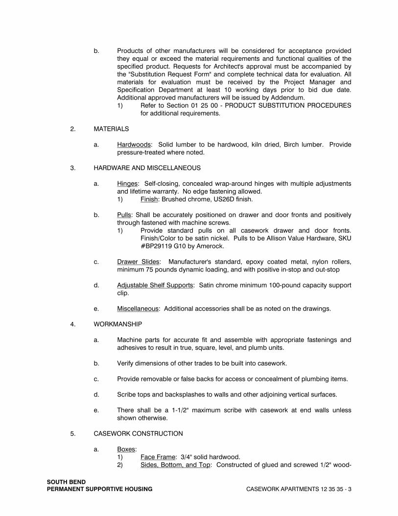
b. Products of other manufacturers will be considered for acceptance provided they equal or exceed the material requirements and functional qualities of the specified product. Requests for Architect's approval must be accompanied by the "Substitution Request Form" and complete technical data for evaluation. All materials for evaluation must be received by the Project Manager and Specification Department at least 10 working days prior to bid due date. Additional approved manufacturers will be issued by Addendum. 1) Refer to Section 01 25 00 - PRODUCT SUBSTITUTION PROCEDURES
for additional requirements.
2. MATERIALS
a. Hardwoods: Solid lumber to be hardwood, kiln dried, Birch lumber. Provide pressure-treated where noted.
3. HARDWARE AND MISCELLANEOUS
a. Hinges: Self-closing, concealed wrap-around hinges with multiple adjustments and lifetime warranty. No edge fastening allowed. 1) Finish: Brushed chrome, US26D finish.
b. Pulls: Shall be accurately positioned on drawer and door fronts and positively through fastened with machine screws. 1) Provide standard pulls on all casework drawer and door fronts.
Finish/Color to be satin nickel. Pulls to be Allison Value Hardware, SKU #BP29119 G10 by Amerock.
c. Drawer Slides: Manufacturer's standard, epoxy coated metal, nylon rollers, minimum 75 pounds dynamic loading, and with positive in-stop and out-stop
d. Adjustable Shelf Supports: Satin chrome minimum 100-pound capacity support clip.
e. Miscellaneous: Additional accessories shall be as noted on the drawings.
4. WORKMANSHIP
a. Machine parts for accurate fit and assemble with appropriate fastenings and adhesives to result in true, square, level, and plumb units.
b. Verify dimensions of other trades to be built into casework.
c. Provide removable or false backs for access or concealment of plumbing items.
d. Scribe tops and backsplashes to walls and other adjoining vertical surfaces.
e. There shall be a 1-1/2" maximum scribe with casework at end walls unless shown otherwise.
5. CASEWORK CONSTRUCTION
a. Boxes: 1) Face Frame: 3/4" solid hardwood. 2) Sides, Bottom, and Top: Constructed of glued and screwed 1/2" wood-

SOUTH BEND PERMANENT SUPPORTIVE HOUSING CASEWORK APARTMENTS 12 35 35 - 4
based composite panel with wood laminate interior and exterior. 3) Back Panel: Constructed of minimum 1/8" hardboard with wood
laminate interior, inset and glued and stapled into sides, bottom, and top.
4) Exposed Panels: Constructed of 1/2" wood-based composite panel with wood laminate interior and exterior, glued and mechanically attached, if required, by manufacturer.
5) Corner Braces: High-impact, injection molded plastic. 6) Hanger Rails: 1/2" wood-based composite at base casework, 1/2"
hardwood plywood at wall casework, and 3/4" hardwood plywood at tall casework.
7) Clear inside depth of wall casework shall be 12", minimum.
b. Fixed and Adjustable Shelves and Dividers: 1) 5/8" thick wood-based composite panel with wood laminate and edge
banding. 2) Number of adjustable shelves provided, unless indicated otherwise on
the Drawings or on the Schedule: a) Tall Casework:
4 up to 84" 5 up to 90" 6 up to 96"
b) Base Casework: 1 up to 36"
c) Wall Hung Casework: 1 up to 24" 2 up to 30" 3 up to 42"
c. Doors and Drawer Fronts: 1) Door profile shall be Advanta “Vista”, 3/4" thick solid birch door frames
with veneered MDF recessed flat center panel. 2) Hinged Doors:
a) Doors 48" and less in height shall have 2 hinges per door. b) Cabinets less than or equal to 30" wide shall be provided with
two (2) doors without center stile.
d. Drawers: Constructed of minimum 3/4" thick hardwood front, back and sides, glued and dovetail jointed. Bottoms constructed of minimum 1/4" hardwood inserted into dado in front, back and sides. Bottoms are glued and stapled into sides.
e. Finish: Multi-step process featuring stain sealer and multi-coat varnish.
f. Removable Sink Bases and Cabinets: 1) Where indicated on the Drawings, provide removable sink bases.
Provide end panels as required, so that a finished appearance is visible if the sink bases are removed.
2) At removable base cabinets, provide operable drawers. g. Pull-Out Shelf Trays: Furnish and install manufacturer’s standard full-depth shelf
trays with full extension drawer slides where noted in the Drawings.

SOUTH BEND PERMANENT SUPPORTIVE HOUSING CASEWORK APARTMENTS 12 35 35 - 5
6. COUNTERTOPS
a. Refer to Section 12 35 35 - CASEWORK.
C. EXECUTION
1. INSTALLATION
a. Shop drawings and installation instructions furnished by the manufacturer shall be strictly adhered to. Mechanics making the installation shall be experienced in this type of work and capable of the highest quality of workmanship.
b. Countertops shall be installed flush against wall. Provide clear sealant at top and around ends of countertops, endsplashes, and backsplashes where they meet wall surfaces and any additional joints, seams or intersections.
c. Cut openings in countertops for sinks or other items required. Cut to size from template furnished by supplier of sinks or use the designated sinks on job. Seal all cut edges with either a one-part silicone sealant or catalyzed varnish.
d. Make use of filler sections and scribe panels to fit casework work into specific dimensions.
e. Provide maintenance instructions to Architect prior to request for final payment.
2. ADJUSTMENT
a. Adjust doors, drawer slides and other moving parts after installation to provide proper operation.
3. CLEANING
a. Exposed surfaces, edges, and casework interiors shall be cleaned, and construction and installation marks removed prior to acceptance by Owner.
b. Supplier of this equipment shall be responsible for the immediate removal and disposal of trash, crating, and construction debris.
END OF SECTION