Addendum 4 & Notice for Inviting Expression of Interest dtd…€¦ · Addendum 4 & Notice for...
25
Uhde India Pvt. Ltd. U6509-3210 / ABM (66-6509-700) 1 of 2 Addendum 4 & Notice for Inviting Expression of Interest dtd. 25/05/12 Client: Bharat Petroleum Corporation Limited, Mahul Tender / Enquiry No. : U6509-3210/ABM Item: Insulation work of Equipments & Piping Project No. : 66-6509-700 Interested vendors to note the following notes / documents as Addendum- 4 & Notice Inviting Expression of Interest to the tender no. U6509-3210/ABM and subsequent Addendum-1, Addendum-2, Addendum-3 of the subject tender. These notes / documents supersede the respective tender clauses and also become the part of tender document. A) Technical Points: Addendum 4 This document is addendum to Technical Specification for Insulation (Doc no. 6509- MQ - EB - 00008 Rev 5.) Vendor to note following changes / additional information to technical specification for insulation after Enquiry, Addendum 1, Addendum 2 & Addendum 3: 1) Note 3.12 of insulation specification 6509-MQ-EB-00008_Rev 05 is modified as “Supplier shall provide reusable / clipping insulation for valves / flanges / manways”. Refer attached indicative sketch for the same. 2) Noise Insulation: Technical Attachments of Type N Noise Insulation for Compressor Package (Additional Scope during TQ after Addendum 3) a. Additional Scope for Equipments in Compressor Package during TQ stage Schedule of Qty for Equipments – Type N (Applicable for items 142-E301, 142- E302 & 142-V303 of PSA Recycle Compressor Package & items 142-E303 & 142-V304 of Tail Gas Export Compressor Package). b. Schedule of Qty for piping-Type N c. Refer Appendix A9–1, Technical specification for Noise Insulation (N) for PSA Recycle Compressor Package received from Kobelco. d. Refer Appendix A9–2, Technical specification for Noise Insulation (N) for Tail Gas Export Compressor Package received from Kobelco.
Transcript of Addendum 4 & Notice for Inviting Expression of Interest dtd…€¦ · Addendum 4 & Notice for...

Uhde India Pvt. Ltd.
U6509-3210 / ABM (66-6509-700) 1 of 2
Addendum 4 & Notice for Inviting Expression of Interest dtd. 25/05/12
Client: Bharat Petroleum Corporation Limited, Mahul Tender / Enquiry No. : U6509-3210/ABM Item: Insulation work of Equipments & Piping
Project No. : 66-6509-700
Interested vendors to note the following notes / documents as Addendum- 4 & Notice Inviting Expression of Interest to the tender no. U6509-3210/ABM and subsequent Addendum-1, Addendum-2, Addendum-3 of the subject tender. These notes / documents supersede the respective tender clauses and also become the part of tender document. A) Technical Points:
Addendum 4 This document is addendum to Technical Specification for Insulation (Doc no. 6509- MQ - EB - 00008 Rev 5.) Vendor to note following changes / additional information to technical specification for insulation after Enquiry, Addendum 1, Addendum 2 & Addendum 3: 1) Note 3.12 of insulation specification 6509-MQ-EB-00008_Rev 05 is modified as
“Supplier shall provide reusable / clipping insulation for valves / flanges / manways”. Refer attached indicative sketch for the same.
2) Noise Insulation: Technical Attachments of Type N Noise Insulation for Compressor
Package (Additional Scope during TQ after Addendum 3)
a. Additional Scope for Equipments in Compressor Package during TQ stage Schedule of Qty for Equipments – Type N (Applicable for items 142-E301, 142-E302 & 142-V303 of PSA Recycle Compressor Package & items 142-E303 & 142-V304 of Tail Gas Export Compressor Package).
b. Schedule of Qty for piping-Type N
c. Refer Appendix A9–1, Technical specification for Noise Insulation (N) for PSA
Recycle Compressor Package received from Kobelco.
d. Refer Appendix A9–2, Technical specification for Noise Insulation (N) for Tail Gas Export Compressor Package received from Kobelco.

Uhde India Pvt. Ltd.
U6509-3210 / ABM (66-6509-700) 2 of 2
B) Commercial Points:
1) All commercial terms & conditions shall be as mentioned in the tender, Addendum-1, Addendum-2 and Addendum-3
2) Expression of interest:
Interested vendors shall send expression of interest on or before 12:00 hrs. of 01.06.2012 to,
UHDE India Pvt. Ltd. Dugal plaza, 2nd Floor, 692 A/3C, Prem Nagar, Bibwewadi Off. Pune-Satara Road, Pune 411 037 (Maharashtra) India. Contact Person: Mr. Abhijeet Mithari / Mr. Vinayak Deo Tel: +91 20 6608 1155 / 9420
3) Offers of the vendors from whom expression of interest has been received within the above-stipulated time only shall be accepted and these vendors shall submit the offers as per instructions to bidders (ITB) on or before 12:00 hrs. of 08.06.2012. No extension for bid submission date shall be granted.
4) Bidders who have already quoted against the subject tender shall note that their
original offer shall remain valid for evaluation and they shall submit compliance to this notice without any deviation.

UUMU2051
Text Box
TYPICAL INDICATIVE SKETCH FOR REFERENCE

dated 15.03.2012
Type of Insulation MOC of EquipmentOperating Temp
(Deg C)Insulation Thickness Position
Area
(Plain Sheet)
Area
(Corrugated Sheet)Total Area Remarks
mm Sq.mtr Sq.mtr Sq.mtr
N (Noise Insulation) CS Below 400 50 mm X 2 Layers* H 40 - 40 Note 1
N (Noise Insulation) CS Below 400 50 mm X 2 Layers* V - 16 16 Note 1
N (Noise Insulation) CS Below 400 50 mm X 2 Layers* H 13 - 13 Note 2
N (Noise Insulation) CS Below 400 50 mm X 2 Layers* V 5.2 - 5.2 Note 2
74.2Total Quantity
BPCL-CCR 66-6509-700
Additional Scope for Equipments in Compressor Package during TQ stage
Schedule of Quantity for Equipments - Type N (Noise Insulation)
NOTE 3:-
The asterisk (*) means that "Lead Plates Are Required". Refer Appendix A9 -1 & A9 - 2 for details.
NOTE 1:-
These items are part of PSA Recycle Compressor Package. Refer attached Appendix A9 - 1 for insulation specification.
NOTE 2:-
These items are part of Tail Gas Export Compressor Package. Refer attached Appendix A9 - 2 for insulation specification.

BPCL - CCR Additional scope for Piping items in PSA
and Tail Gas Export Compressor Package
during TQ stage
Schedule of Quantity for Piping
66-6509-700
Page: 1 of 1
INSULATION TYPE INSULATION THK. TYPE SIZE QUANTITY UNITS TEMP. MOC
1/2" 0.1 Mts
3/4" 6.2 Mts
1" 0.3 Mts
1 1/2" 5.7 Mts
6" 33.9 Mts
8" 45.1 Mts
10" 112.5 Mts
12" 0.2 Mts
14" 8.1 Mts
18" 10.5 Mts
6" 1 Nos
8" 1 Nos
10" 6 Nos
3/4" 3 Nos
6" 17 Nos
8" 13 Nos
10" 35 Nos
12" 1 Nos
14" 6 Nos
18" 5 Nos
1 1/2" 3 Nos
10" 3 Nos
14" 2 Nos18" 1 Nos
8" 1 Nos
12" 2 Nos
14" 1 Nos
1/2" 1 Nos
3/4" 37 Nos
1" 1 Nos
1 1/2" 25 Nos
WLET 2" 6 Nos
NIPPLE 1/2" 2 Nos
2" 1 Nos
6" 19 Nos
8" 13 Nos
10" 21 Nos
12" 2 Nos
14" 3 Nos
18" 8 Nos
3/4" 15 Nos
1 1/2" 27 Nos
1" 3 Nos
3/4" 14 Nos
1" 2 Nos
1/2" 3 Nos
3/4" 37 Nos
1 1/2" 6 Nos
6" 4 Nos
8" 3 Nos
10" 4 Nos
14" 1 Nos
18" 2 Nos
1 1/2" 2 Nos
6" 2 Nos
8" 2 Nos
10" 5 Nos
14" 1 Nos
18" 1 Nos
NOTE: The asterisk(*) in the table above means that “Lead Plates Are Required”
50mm x 2 layers*
100mm x 1 Layer
50mm x 2 layers*
REDUCER
SOCKLET
PIPE
ELBOW-45
ELBOW-90
N
SOUND
INSULATION
MTO
CS
BLIND FLANGE
VALVES
SPECIAL
PARTS(SPECTACLE
BLIND)
WN FLANGE
SW FLANGE
TEE
Operting temp
below 400 deg c

P. 14
B195556
10. SOUND INSULATION WORK Sound insulation work is to be performed to equipment and piping emitting considerable sound according to RECOMMENDED SOUND INSULATION PROCEDURE. Sound insulation materials for the inlet silencer, discharge silencer, bypass cooler and the valves of process gas line, and the necessary insulation work should be performed by customers or others.
11. RECOMMENDED SOUND INSULATION PROCEDURE 11.1 General
This manual presents recommended sound insulation procedures and materials for KOBELCO-Screw Compressors, and piping and equipment in the process line. It is recommended to perform sound insulation work in accordance with the procedures described herein.
11.2. Sound insulating material
Equivalent to the following materials may be used:
Identification Description a JIS A9504 Rock Wool Blanket No.2 with metal lath, 100mm thick
(heat resistance up to 650℃) RW
b JIS A9504 Rock Wool Heat Insulating Band No.2, 50mm thick. Belt-like insulator backed by victoria lawn (heat resistance up to 300℃)
IW Galvanized Iron Wire JIS G3541 Galvanized Low Carbon Steel Wire for Armoring Cables, SWMGB, BWG #18 (dia : 1.24 mm)
IP Galvanized or Color Iron Plate (silver) JIS G3302 Galvanized Iron Sheet, SPGC Z18, thickness of 0.40 mm
WN Hexagonal Wire Netting JIS G3554 HX-G #16 (dia. : 0.5mm)
LP Lead Plate JIS H4301 Lead Plate (thickness of 0.5 mm)
TP Self Tapping Screws for Reinforcement JIS B1122 Cross-Recessed Head Tapping Screws - Pan Head Type Material : Stainless Steel Size : 3mm dia. x 13mm length or larger
SC Sealing Compound Shinetsu Silicon #KE45 or equivalent. All gap shall be filled with sealing compound.
uumu2012
Text Box
Technical Specification for Noise Insulation (N) for PSA Recycle Compressor Package received from Kobelco
uumu2012
Text Box
Total Pages 10 (Page no. 14 to 23)
uumu2012
Text Box
Appendix A9-1

P. 15
B195556
11.3. Recommended Application of Sound Insulation
The following sound insulation should be applied:
Place of application Description Remarks
1 Main Gas Line
a Suction line
b Discharge Line
c Bypass Line
50mm × 2 layers*
50mm × 2 layers*
50mm × 2 layers*
2 Compressor
a Inlet Nozzle
b Discharge Nozzle
Not applied
Not applied
3 Suction Silencer 50mm × 2 layers*
4 Discharge Silencer 50mm × 2 layers*
5 Interstage cooler
6 PSA Recycle Cooler
7 Interstage Drum
50mm × 2 layers*
8 Flange Portion 100mm × 1 layer
9 Valve 100mm × 1 layer
10 Piping Support With rubber NOTES
1) Typical work procedures are described in Para. 11.4.
2) For the convenience of maintenance of compressors, pipes and other equipment, the sound insulation, if applied, at flanges or connections between piping and equipment shall be non-continuous or removable; i.e,. each piping shall be insulated as a single unit.
3) The line downstream of the bypass connection should be insulated with the same procedures as the bypass line.
4) Piping supports shall be isolated from possible vibration of piping by using rubber or vibration damper.
5) The asterisk(*) in the table above means that “Lead Plates Are Required”.
uumu2012
Text Box
142-E301
uumu2012
Text Box
142-E302
uumu2012
Text Box
142-V303

P. 16
B195556
11.4. Procedure of Work
11.4.1. General This paragraph presents general procedures for sound insulation. Detailed procedures shall be established by those who are responsible for the work.
11.4.2. General Remarks The following are general remarks on the work:
(1) Insulation materials which contain chlorine or may evacuate chlorine shall not be used on stainless steel products.
(2) Plates, studs, pins, or clips properly spaced shall be provided on a vertical piping or equipment to secure the insulation.
(3) Surface to be insulated shall be dry, and foreign matter shall be removed with solvent or the like.
(4) Insulation on both sides of flanged joints shall be tapered to permit stud removal without damage of the insulation.
(5) Edges of insulation openings such as round manholes, nozzles, cutouts of stud removal, pipe supports, and other attachments shall be sealed to prevent water from entering. Metal covers may be used if temperature exceeds the usable range of weather proofing coatings or sealing compounds.
(6) Laps of jackets shall be positioned to shed water. The minimum longitudinal lap shall be as follows:
Piping or Equip. Dia. Min. Lap 24” O.D or less 50mm Over 24” O.D 75mm When jackets are fixed by self tapping screws in lieu of lock seaming, the minimum circumferential lap shall be as follows:
Piping or Equip. Dia. Min. Lap 24” O.D or less 50mm Over 24” O.D 75mm The location of lap shall be determined so as to prevent water from entering.

P. 17
11.4.3. Typical Procedure of Insulating Work
11.4.3.1. 50mm (Rock wool) x 2 layers with lead plates. This procedure is for silencers, piping and other pressure vessels such as gas coolers, separators as specified.
Wind RW-b(rock wool heat insulating bands No.2, 50mm thick) onto the object, and bind it with IW(BWG #18 galvanized iron wire) at a regular interval of about200mm. After that, cover it with LP(lead plates) and bind it with IW(galvanized iron wire). Repeat the same process on it.
IP
IW
RW
Pipe,etc.
LP
Lock seaming or TS
Fig. 1
B195556
Cover it with IP(galvanized iron plate or color iron plate) instead of LP(lead plate), and fix it by lock seaming or by TS(self tapping screws) and galvanized steel bands.

P. 18
11.4.3.2. 50mm (Rock wool) x 2 layers without lead plates.
This procedure is for silencers, piping, oil recovery tank and other pressure vessels such as gas coolers, separators as specified.
50 50 IP
IW
RW
Pipe,etc.
Lock seaming or TS
IP
Lock seaming or TS
B195556
Wind RW-b(rock wool heat insulating bands No.2, 50mm thick) onto the object, and bind it with IW(BWG #18 galvanized iron wire) at a regular interval of about200mm. After that, cover it with IP(galvanized iron plate or color iron plate), and fix it by lock seaming or TS(self tapping screws) and galvanized steel bands.
Fig. 2
Repeat the same process on it.

P. 19
11.4.3.3. 100mm x 1 layer without lead plates
This procedure is for silencers, piping and other pressure vessels such as gas coolers, separators as specified.
B195556
Wind RW-a(rock wool heat insulating bands No.2, 100mm thick) onto the object, and bind it with IW(BWG #18 galvanized iron wire) at a regular interval of about 200mm. After that, cover it with IP(galvanized iron plate or color iron plate), and fix it by lock seaming or by TS(self tapping screws) and galvanized steel bands.
Pipe etc.
RW
IW IP
100
Lock seaming or TS
200
Fig. 3
P. 20
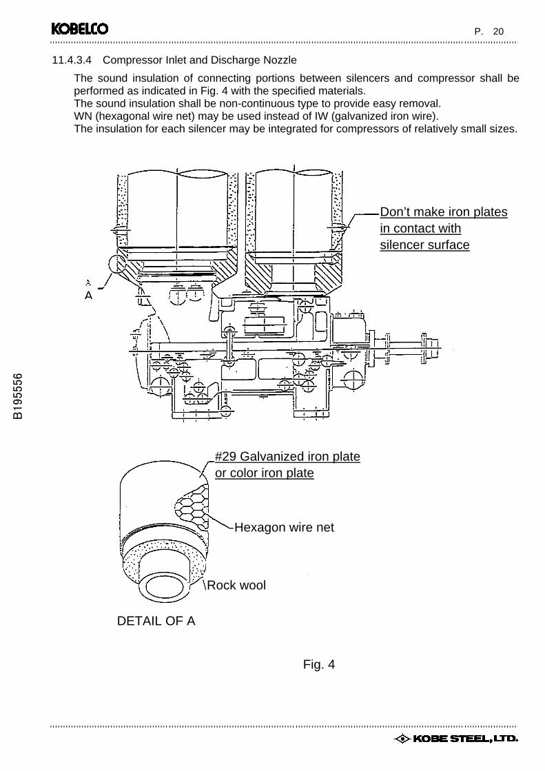
11.4.3.4 Compressor Inlet and Discharge Nozzle
The sound insulation of connecting portions between silencers and compressor shall be performed as indicated in Fig. 4 with the specified materials. The sound insulation shall be non-continuous type to provide easy removal. WN (hexagonal wire net) may be used instead of IW (galvanized iron wire). The insulation for each silencer may be integrated for compressors of relatively small sizes.
Don’t make iron platesin contact with silencer surface
A
B195556
#29 Galvanized iron plateor color iron plate
Hexagon wire net
Rock wool
DETAIL OF A
Fig. 4

P. 21
11.4.3.5. Flange Connecting Portion
The sound insulation of flange connecting portions shall be performed as indicated in Fig. 5 with the specified materials. The sound insulation shall be non-continuos type to provide easy removal. WN(hexagonal wire net) may be used instead of IW(galvanized iron wire) as shown in Fig.5.
For easy maintenance, it is acceptable not to perform sound insulation to this portion. In this case, this portion shall be arranged as indicated in Fig.6. Edged of insulating jacket shall be sealed to prevent water from entering.
Fig. 5
Don't make iron plate contact with pipe or fl
PipeIntermediate flange
B195556
Intermediate flange Bend
Pipe
Don't make iron plates in contact with pipes or flanges
Fig. 6
P. 22
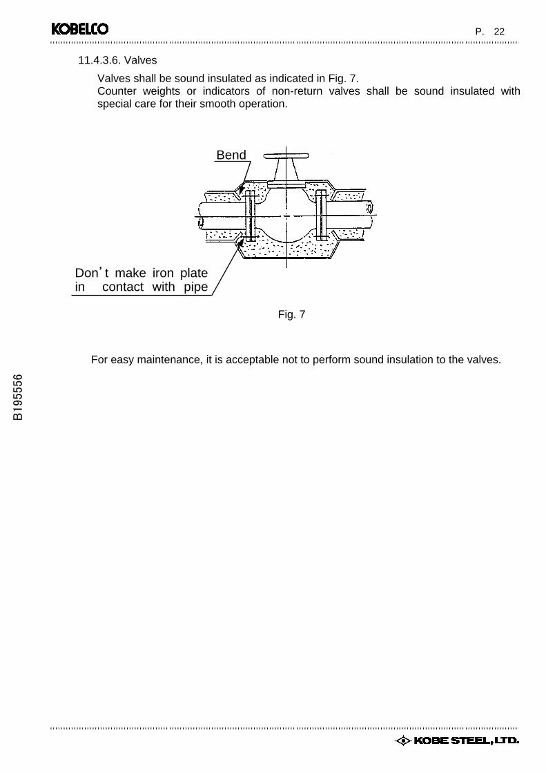
11.4.3.6. Valves
Valves shall be sound insulated as indicated in Fig. 7. Counter weights or indicators of non-return valves shall be sound insulated with special care for their smooth operation.
Fig. 7
Bend
Don’t make iron plate in contact with pipe
For easy maintenance, it is acceptable not to perform sound insulation to the valves.
B195556

P. 23
11.4.3.7. Bending Portion The sound insulation of bending portion shall be performed as indicated in Fig. 8 with the specified materials. The detail procedure for bending portion is the same as Para. 11.4.3.1 to 11.4.3.3.
Fig. 8
11.4.3.8 Gas Cooler
B195556 The sound insulation should be performed on gas side when shell side is gas passage, but
the water chamber does not require the insulation The work should be performed with due care to ensure easy disassembly of the gas cooler.

P. 14
B195556
10. SOUND INSULATION WORK Sound insulation work is to be performed to equipment and piping emitting considerable sound according to RECOMMENDED SOUND INSULATION PROCEDURE. Sound insulation materials for the inlet silencer, discharge silencer will be supplied by KSL. However sound insulation material for Tail Gas Export Cooler, Tail Gas Export Drum and pipings and the valves of process gas line, and the necessary insulation work should be performed by customers or others.
11. RECOMMENDED SOUND INSULATION PROCEDURE 11.1 General
This manual presents recommended sound insulation procedures and materials for KOBELCO-Screw Compressors, and piping and equipment in the process line. It is recommended to perform sound insulation work in accordance with the procedures described herein.
11.2. Sound insulating material
Equivalent to the following materials may be used:
Identification Description a JIS A9504 Rock Wool Blanket No.2 with metal lath, 100mm thick
(heat resistance up to 650℃) RW
b JIS A9504 Rock Wool Heat Insulating Band No.2, 50mm thick. Belt-like insulator backed by victoria lawn (heat resistance up to 300℃)
IW Galvanized Iron Wire JIS G3541 Galvanized Low Carbon Steel Wire for Armoring Cables, SWMGB, BWG #18 (dia : 1.24 mm)
IP Galvanized or Color Iron Plate (silver) JIS G3302 Galvanized Iron Sheet, SPGC Z18, thickness of 0.40 mm
WN Hexagonal Wire Netting JIS G3554 HX-G #16 (dia. : 0.5mm)
LP Lead Plate JIS H4301 Lead Plate (thickness of 0.5 mm)
TP Self Tapping Screws for Reinforcement JIS B1122 Cross-Recessed Head Tapping Screws - Pan Head Type Material : Stainless Steel Size : 3mm dia. x 13mm length or larger
SC Sealing Compound Shinetsu Silicon #KE45 or equivalent. All gap shall be filled with sealing compound.
uumu2012
Text Box
Technical Specification for Noise Insulation (N) for Tail Gas Export Compressor Package received from Kobelco
uumu2012
Text Box
Total Pages 10 (Page no. 14 to 23)
uumu2012
Text Box
Appendix A9-2

P. 15
B195556
11.3. Recommended Application of Sound Insulation
The following sound insulation should be applied:
Place of application Description Remarks
1 Main Gas Line
a Suction line
b Discharge Line
c Bypass Line
50mm × 2 layers*
50mm × 2 layers*
50mm × 2 layers*
2 Compressor
a Inlet Nozzle
b Discharge Nozzle
c. Discharge Short Spool Pipe between Compressor and Discharge Silencer
Not applied
Not applied
50mm × 2 layers*
3 Suction Silencer 50mm × 2 layers*
4 Discharge Silencer 50mm × 2 layers*
5 Tail Gas Export cooler
6 Tail Gas Export Drum 50mm × 2 layers*
7 Flange Portion 100mm × 1 layer
8 Valve 100mm × 1 layer
9 Piping Support With rubber NOTES
1) Typical work procedures are described in Para. 11.4.
2) For the convenience of maintenance of compressors, pipes and other equipment, the sound insulation, if applied, at flanges or connections between piping and equipment shall be non-continuous or removable; i.e,. each piping shall be insulated as a single unit.
3) The line downstream of the bypass connection should be insulated with the same procedures as the bypass line.
4) Piping supports shall be isolated from possible vibration of piping by using rubber or vibration damper.
5) The asterisk(*) in the table above means that “Lead Plates Are Required”.
uumu2012
Text Box
142-E303
uumu2012
Text Box
142-V304

P. 16
B195556
11.4. Procedure of Work
11.4.1. General This paragraph presents general procedures for sound insulation. Detailed procedures shall be established by those who are responsible for the work.
11.4.2. General Remarks The following are general remarks on the work:
(1) Insulation materials which contain chlorine or may evacuate chlorine shall not be used on stainless steel products.
(2) Plates, studs, pins, or clips properly spaced shall be provided on a vertical piping or equipment to secure the insulation.
(3) Surface to be insulated shall be dry, and foreign matter shall be removed with solvent or the like.
(4) Insulation on both sides of flanged joints shall be tapered to permit stud removal without damage of the insulation.
(5) Edges of insulation openings such as round manholes, nozzles, cutouts of stud removal, pipe supports, and other attachments shall be sealed to prevent water from entering. Metal covers may be used if temperature exceeds the usable range of weather proofing coatings or sealing compounds.
(6) Laps of jackets shall be positioned to shed water. The minimum longitudinal lap shall be as follows:
Piping or Equip. Dia. Min. Lap 24” O.D or less 50mm Over 24” O.D 75mm When jackets are fixed by self tapping screws in lieu of lock seaming, the minimum circumferential lap shall be as follows:
Piping or Equip. Dia. Min. Lap 24” O.D or less 50mm Over 24” O.D 75mm The location of lap shall be determined so as to prevent water from entering.

P. 17
11.4.3. Typical Procedure of Insulating Work
11.4.3.1. 50mm (Rock wool) x 2 layers with lead plates. This procedure is for silencers, piping and other pressure vessels such as gas coolers, separators as specified.
Wind RW-b(rock wool heat insulating bands No.2, 50mm thick) onto the object, and bind it with IW(BWG #18 galvanized iron wire) at a regular interval of about200mm. After that, cover it with LP(lead plates) and bind it with IW(galvanized iron wire). Repeat the same process on it.
IP
IW
RW
Pipe,etc.
LP
Lock seaming or TS
Fig. 1
B195556
Cover it with IP(galvanized iron plate or color iron plate) instead of LP(lead plate), and fix it by lock seaming or by TS(self tapping screws) and galvanized steel bands.

P. 18
11.4.3.2. 50mm (Rock wool) x 2 layers without lead plates.
This procedure is for silencers, piping, oil recovery tank and other pressure vessels such as gas coolers, separators as specified.
50 50 IP
IW
RW
Pipe,etc.
Lock seaming or TS
IP
Lock seaming or TS
B195556
Wind RW-b(rock wool heat insulating bands No.2, 50mm thick) onto the object, and bind it with IW(BWG #18 galvanized iron wire) at a regular interval of about200mm. After that, cover it with IP(galvanized iron plate or color iron plate), and fix it by lock seaming or TS(self tapping screws) and galvanized steel bands.
Fig. 2
Repeat the same process on it.

P. 19
11.4.3.3. 100mm x 1 layer without lead plates
This procedure is for silencers, piping and other pressure vessels such as gas coolers, separators as specified.
B195556
Wind RW-a(rock wool heat insulating bands No.2, 100mm thick) onto the object, and bind it with IW(BWG #18 galvanized iron wire) at a regular interval of about 200mm. After that, cover it with IP(galvanized iron plate or color iron plate), and fix it by lock seaming or by TS(self tapping screws) and galvanized steel bands.
Pipe etc.
RW
IW IP
100
Lock seaming or TS
200
Fig. 3

P. 20
11.4.3.4 Compressor Inlet and Discharge Nozzle
The sound insulation of connecting portions between silencers and compressor shall be performed as indicated in Fig. 4 with the specified materials. The sound insulation shall be non-continuous type to provide easy removal. WN (hexagonal wire net) may be used instead of IW (galvanized iron wire). The insulation for each silencer may be integrated for compressors of relatively small sizes.
Don’t make iron platesin contact with silencer surface
A
B195556
#29 Galvanized iron plateor color iron plate
Hexagon wire net
Rock wool
DETAIL OF A
Fig. 4

P. 21
11.4.3.5. Flange Connecting Portion
The sound insulation of flange connecting portions shall be performed as indicated in Fig. 5 with the specified materials. The sound insulation shall be non-continuos type to provide easy removal. WN(hexagonal wire net) may be used instead of IW(galvanized iron wire) as shown in Fig.5.
For easy maintenance, it is acceptable not to perform sound insulation to this portion. In this case, this portion shall be arranged as indicated in Fig.6. Edged of insulating jacket shall be sealed to prevent water from entering.
Fig. 5
Don't make iron plate contact with pipe or fl
PipeIntermediate flange
B195556
Intermediate flange Bend
Pipe
Don't make iron plates in contact with pipes or flanges
Fig. 6

P. 22
11.4.3.6. Valves
Valves shall be sound insulated as indicated in Fig. 7. Counter weights or indicators of non-return valves shall be sound insulated with special care for their smooth operation.
Fig. 7
Bend
Don’t make iron plate in contact with pipe
For easy maintenance, it is acceptable not to perform sound insulation to the valves.
B195556

P. 23
11.4.3.7. Bending Portion The sound insulation of bending portion shall be performed as indicated in Fig. 8 with the specified materials. The detail procedure for bending portion is the same as Para. 11.4.3.1 to 11.4.3.3.
Fig. 8
11.4.3.8 Gas Cooler
B195556 The sound insulation should be performed on gas side when shell side is gas passage, but
the water chamber does not require the insulation The work should be performed with due care to ensure easy disassembly of the gas cooler.