ADAPTORS, TRANSITION PLATES, AND STANCHIONS · Adaptors, Transition Plates, and Stanchions For...
46
10-1 www.phdinc.com • (800) 624-8511 CAT-05 ADAPTORS, TRANSITION ADAPTORS, TRANSITION PLATES, AND STANCHIONS TRANSITION PLATES STANCHIONS ADAPTORS FOR EASE OF CONNECTING PHD PRODUCTS TOGETHER, PROVIDING THE MOST VERSATILE SOLUTION IN THE INDUSTRY. need new unit from engineering ADAPTORS, TRANSITION PLATES, AND STANCHIONS
Transcript of ADAPTORS, TRANSITION PLATES, AND STANCHIONS · Adaptors, Transition Plates, and Stanchions For...

10-1
www.phdinc.com • (800) 624-8511
CAT-
05
ADAPTORS,
TRANSITION
ADAPTORS, TRANSITION PLATES,AND STANCHIONS
TRANSITION PLATES
STANCHIONS
ADAPTORS
FOR EASE OF CONNECTING PHDPRODUCTS TOGETHER, PROVIDINGTHE MOST VERSATILE SOLUTIONIN THE INDUSTRY. need new unit
from engineering
ADAPTORS, TRANSITION PLATES,AND STANCHIONS

www.phdinc.com • (800) 624-8511
CAT-05
ADAPTORS,TRANSITION
10-2
Adaptors, Transition Plates, and StanchionsFor Modular Automation• REDUCES ENGINEERING TIME• SIMPLIFIES DESIGN• COST-EFFECTIVE• ELIMINATES FABRICATION
Simplify the design of your automation solutions usingPHD’s wide range of adaptors, transition plates, and stanchions.The use of standard hardware makes it easy to combine axes ofmotion. The hardware provides an efficient means of assemblingindividual actuators into a complete automation device. Anunlimited number of combinations can be achieved to satisfyyour specific motion requirements.
A complete line of stanchions are also offered. Stanchionsprovide a rigid support for mounting the assembled device abovethe work surface. Additionally, PHD stanchions are easilyadjustable for achieving specific height requirements.
Integrating devices using standard PHD actuators andhardware will add greatly to the cost effectiveness of your design.
GUIDELINES FOR MODULAR AUTOMATION

10-3
www.phdinc.com • (800) 624-8511
CAT-
05
ADAPTORS,
TRANSITION
GUIDELINES FOR MODULAR AUTOMATION
HOW TO USE THIS SECTIONThis section covers available hardware for the creation of PHD
Modular Automation Devices.Each hardware subsection contains a grid layout showing the
most common combinations of PHD actuators together with theproper Adaptor, Transition Plate, or Stanchion, and hardware tofacilitate interconnection.
The proper sizing of PHD actuators is derived from theindividual product catalog sections.
Follow the sequence below when selecting mechanicalcomponents for a parts handling or other automation device.
STEP 1: Determine the weight of the part to be moved.
STEP 2: Determine the best path(s) of motion within acomplete cycle.
STEP 3: Determine cycle and intermediate dwell times to arrive atactual transfer velocities.
STEP 4: Select the proper components for weight, path(s), andvelocities beginning with the component closest to thepart to be moved (e.g., gripper or vacuum cup). Thendetermine the size and type of the next component oractuator based on the same parameters, but including themass of all components supported by this member and soon until the stationary member is determined.
PHD components and capacities are shown in thefollowing sections:
Device SectionCylinders 1Slides 2Escapements 3Grippers 4Rotary Actuators 5Multi-Motion Actuators 6
Consult PHD for technical assistance to aid in choosing theproper components and control (electronic) interfaces.
HOW TO ESTABLISH PRIMARY/SECONDARY UNITS
When a product is a “primary unit,” the transition plate will bemounted to the “dynamic component” of that product (tool plate,saddle, shaft, etc.)
When a product is a “secondary unit,” the transition plate willbe mounted to the “stationary component” of that product (endblocks, body, housing, etc.)
If dowel pin holes are required, consult PHD.

www.phdinc.com • (800) 624-8511
CAT-05
ADAPTORS,TRANSITION
10-4
ADAPTOR/ACTUATOR COMBINATIONS
MINIATURE GRIPPERS LARGER GRIPPERS
SEE REFERENCEDPAGES FOR PROPERADAPTOR SIZE AND
KIT NUMBER
SECTION 4 SECTION 4
NON-ROTATING RODCYLINDERS
SECTION 1 10-6 to 10-13 10-6 to 10-9
MINIATURE ROTARYACTUATORS
SECTION 510-10 to 10-13 10-10 to 10-13
LARGER ROTARYACTUATORS
SECTION 510-6 to 10-9
MULTI-MOTIONACTUATORS
10-6 to 10-13 10-6 to 10-9SECTION 6
SECONDARY UNIT
PRIMARY
UNIT
10-6 to 10-13

10-5
www.phdinc.com • (800) 624-8511
CAT-
05
ADAPTORS,
TRANSITION
ADAPTOR/ACTUATOR COMBINATIONS
PHD Adaptors also provide an easy means of attaching tooling, fixturing, and arms for the creation of pick and place devices. They provide abolt pattern on the end of various PHD Actuator shafts making it easy to mount other PHD products and customer-provided tooling.
MULTI-MOTIONACTUATORS
SLIDESLARGER ROTARYACTUATORS
SECTION 6 SECTION 2
10-10 to 10-13
SECTION 5
10-6 to 10-910-6 to 10-9 10-6 to 10-9
10-6 to 10-910-6 to 10-9 10-6 to 10-9
10-6 to 10-9
SECONDARY UNITMINIATURE ROTARY
ACTUATORS
SECTION 5
10-10 to 10-13
10-6 to 10-13
10-6 to 10-13
10-6 to 10-13
NOT AVAILABLE
10-6 to 10-9
NOT AVAILABLENOT AVAILABLE

www.phdinc.com • (800) 624-8511
CAT-05
ADAPTORS,TRANSITION
10-6
HOLE PATTERN ORIENTATION
HUB ADAPTORS ALLOW COMBININGACTUATORS TO A ROUND OUTPUT SHAFT
EXAMPLE 2EXAMPLE 1
NOTE: Square hole pattern may be rotated in 5° increments up to 85°. Rectangular hole patterns may be rotated in 5° increments up to 175°.
HOLEPATTERN
EXAMPLE 3
KEYWAYHOLEPATTERN
20°
KEYWAY5°
KEYWAY ANDHOLE PATTERN 0°
KIT NO. 10812-00-0051 KIT NO. 10812-01-0051 KIT NO. 10812-04-0051
CL CL CL CL CL
HUB ADAPTORS: IMPERIAL UNITS
ORDERING DATA
To order specify:Hub Size, Hole Pattern Orientation, and HolePattern Number.
NOTES:1) Hub Adaptor must be used with -PK Rod End
on series 1-8000 Multi-Motion Actuators, -Hoption on Non-Rotating Rod Cylinders, and-K Shaft on Series 1-8000 Rotary Actuators.
2) Hub adaptor kit includes all hardware tomount component to hub, and hub to shaft.
3) Stroke or travel related secondary unitsrequire a customer provided plate (NPCylinders, SM Slides).
10812 00HOLE PATTERN ORIENTATION
- 0051-
Relationship of the hole pattern centerline to centerlineof the keyway. The pattern may be rotated clockwisein 5° increments.00 - Hole pattern centerline is the same as the keyway01 - Hole pattern centerline, 5° clockwise of keyway02 - Hole pattern centerline, 10° clockwise of keywayEtc… See below
HOLE PATTERNSelect proper 4 digit numberfrom matrix on 10-7 & 10-8.
SHAFT DIA. SIZE NO.
HUB SIZE
1/2 = 108113/4 = 108127/8 = 10813
1-1/8 = 108141-3/4 = 10815
SHAFT DIA. SIZE NO.

10-7
www.phdinc.com • (800) 624-8511
CAT-
05
ADAPTORS,
TRANSITION
MATRIX: HUB ADAPTORS-IMPERIAL UNITS
-1781
108121-3/8" BORE
NON-ROTATINGROD CYLINDER3-4000 MULTI-
MOTIONACTUATOR
108111-1/8" BORE
NON-ROTATINGROD CYLINDER1-2000 ROTARY
& MULTI-MOTION
ACTUATOR
108133-4000 ROTARY
ACTUATORS
108145-6000 ROTARY
& MULTI-MOTION
ACTUATORS
108157-8000 ROTARY
& MULTI-MOTION
ACTUATORSPHD UNIT
19032 19x9x
8430
862x 1532x 1536x
863x 1533x 1537x
864x 1534x 1538x
SHAFT DIAMETER
865x 1535x 1539x
GRBx41
GRBx51
GRBx61
GRBx71
-0981
-0051
3/4
-0061
-1621
-1731
-1741
-1751
-1761
-1791
-1771
-0001
-0981
-0041
-0041
-0051
1/2
-1731
-1741
-1751
-0001
-1621
-0981
-0051
-0061
-1731
-1741
-1751
-1781
-1761
-1791
-1771
-0001
7/8
-0061
-0071
-1731
-1741
-1751
-1781
-1761
-1791
-1801
-1771
-0001
1-1/8
-0071
-1531
-1731
-1741
-1751
-1781
-1791
-1761
-1801
-1771
-1811
-0001
1-3/4
-1521 -1521 -1521
PRIMARY UNIT
SECONDARY
UNIT
-1631
GRBx3x
-0951
-1601
GRCx4x
GRCx5x
GRCx6x
SAx114SBx114SAx120SBx120SAx132SBx132SDxx2SExx2SDxx3
SExx3
SDxx4
SExx4
SDxx5
SExx5
SDxx6
SExx6
BLANK HUBADAPTOR FORCUSTOMER TOOLING
GRDx3x
GRDx4x
GRDx5x
GRDx6x
NOTE: For shaded areas or units notlisted, see page 10-9 to see if requiredmounting pattern is available. If not,consult PHD.
GRIP
PERS
POW
ERED
SLI
DES
GRCx31 -1601 -1601
MOUNTINGHOLE PATTERN
LOCATION
BOTTOM
(OPPOSITEOF JAWS)
BOTTOM
(SURFACEPERPENDICULAR
TO TOOLPLATE POS. #3)
-0981
-0061
-0051
-1621
-1631 -1631
-1601
-1801 -1801

www.phdinc.com • (800) 624-8511
CAT-05
ADAPTORS,TRANSITION
10-8
PHD UNIT
018075
100020003000400050006000
108121-3/8" BORE
NON-ROTATINGROD CYLINDER3-4000 MULTI-
MOTIONACTUATOR
3/4
108111-1/8" BORE
NON-ROTATINGROD CYLINDER1-2000 ROTARY
& MULTI-MOTION
ACTUATOR
-2581
1/2
108133-4000 ROTARY
ACTUATORS
7/8
108145-6000 ROTARY
& MULTI-MOTION
ACTUATORS
1-1/8
108157-8000 ROTARY
& MULTI-MOTION
ACTUATORS
1-3/4
RAS120
MOUNTINGHOLE PATTERN
LOCATION
RAS125
RAS132
RAS140
RAS150
RAS120
FRONT &BACK
(PARALLELTO SHAFT
POS. #2 & #4)
RAS125
RAS132
RAS140
RAS150
BOTTOM
(PERP. TOSHAFT
POS. #3)
FRONT &BACK
(PARALLELTO SHAFT
POS. #2 & 4)
BOTTOM
(PERP. TOSHAFT
POS. #3)
-2601
-2621 -2621
-2641 -2641 -2641
-2661
-2481 -2481 -2481 -2481
-2501 -2501 -2501 -2501
-2521 -2521
-2541
-2561
-3491
-3511 -3511
-3531
-3771
-3791
-3831
-3851
-3831 -3831
-3851 -3851 -3851
-3871 -3871 -3871
-3891 -3891
-3911 -3911
-0181
-3811
-0051
-0181
-0051
-0181
-0051
-0181
-0221 -0221 -0221 -0301**
-0241 -0321**
SHAFT DIAMETER
BLANK HUBADAPTOR FORCUSTOMER TOOLING
PRIMARY UNIT
SECONDARY
UNIT
***RLS112
***RLS116
***RLS120
***RLS125
***RLS132
***RLS140
***RLS150
***RLS163
RLS112
RLS116
RLS120
RLS125
RLS132
RLS140
RLS150
RLS163
-0001-0001-0001-0001-0001
018050
ROTA
RY A
CTUA
TORS
NOTES:1) For shaded areas or units not listed, see page 10-9 to see if required mounting pattern
is available. If not, consult PHD.2) ** Requires Rotary Actuator to be mounted to the bottom mounting flanges. See Options
in the Rotary Actuator section.3)*** Patterns in RLS bodies are not centered to pinion shaft.
-0161 -0161 -0161
TOP& BOTTOM
(PERP. TOSHAFT
POS. #1 & #3)
-2521 -2521
-0051
-0241 -0241
Rx1xRx1xRx1xRx1xRx1xRx1x
MATRIX: HUB ADAPTORS-IMPERIAL UNITS

10-9
www.phdinc.com • (800) 624-8511
CAT-
05
ADAPTORS,
TRANSITION
DIMENSIONS: HUB ADAPTORS
MOUNTING HOLE PATTERN DIMENSIONS
HUB KIT LETTER DIMENSIONSDASH NO. N M ØL
-000x — — —-004x 1.250 1.250 .204 THRU-005x 1.500 1.500 .281 THRU-006x 1.750 1.750 .344 THRU-012x 2.250 1.250 .204 THRU-016x 1.500 1.000 .177 THRU-018x 2.000 1.500 .204 THRU-042x 1.000 1.000 10-24 UNC THRU-045x 1.500 1.500 1/4-20 UNC THRU-048x 1.750 1.750 5/16-18 UNC THRU-054x 2.000 — .406 THRU-095x 1.250 1.250 .281 THRU-098x 1.535 1.535 .206 THRU-110x 1.688 1.688 1/4-20 UNC THRU-122x 1.102 1.102 .189 THRU-160x 1.181 1.181 .206 THRU-161x 1.457 1.457 .281 THRU-173x 1.625 — 1/4-20 UNC THRU-174x 1.875 — 5/16-18 UNC THRU-175x 2.000 — 3/8-16 UNC THRU-240x 1.339 1.339 .281 THRU-258x 1.574 1.180 .204 THRU-260x 1.772 1.378 .206 THRU-349x 1.378 1.398 .204 THRU-377x .630 1.378 .136 THRU-379x .650 1.535 .136 THRU-381x .906 1.516 .154 THRU-383x 1.182 1.968 .204 THRU-385x 1.260 2.202 .204 THRU
108111/2 SHAFT DIAMETER
SHAFT HUB HUB LETTER DIMENSIONDIA. WEIGHT (lb) KIT NO. A B C D E F G H J K1/2 .30 10811-xx-xxxx 2.900 1.125 .375 1.250 .501 .812 .438 1/8 x .81 DP 8-32 #103/4 .75 10812-xx-xxxx 3.900 1.750 .500 1.625 .751 1.375 .563 3/16 x 1.27 DP 10-32 5/167/8 .70 10813-xx-xxxx 3.900 1.750 .500 1.625 .876 1.375 .563 3/16 x 1.27 DP 10-32 5/16
1-1/8 1.25 10814-xx-xxxx 4.700 1.875 .562 1.950 1.126 1.437 .625 1/4 x 1.38 DP 1/4-20 3/81-3/4 3.25 10815-xx-xxxx 5.950 3.000 .750 3.250 1.751 2.375 .875 3/8 x 2.31 DP 3/8-16 1/2
108123/4 SHAFT DIAMETER
HUB KIT LETTER DIMENSIONSDASH NO. N M ØL
-000x — — —-005x 1.500 1.500 .281 THRU-006x 1.750 1.750 .344 THRU-012x 2.250 1.250 .204 THRU-013x 2.750 1.500 .281 THRU-016x 1.500 1.000 .177 THRU-018x 2.000 1.500 .204 THRU-022x 2.000 2.000 .344 THRU-024x 2.500 2.000 .406 THRU-042x 1.000 1.000 10-24 UNC x .500 DP-045x 1.500 1.500 1/4-20 UNC THRU-048x 1.750 1.750 5/16-18 UNC THRU-061x 2.250 1.250 .281 THRU-062x 2.750 1.500 .344 THRU-077x 1.250 1.250 10-24 UNC x .500 DP-098x 1.535 1.535 .206 THRU-152x 1.457 2.677 .344 THRU-160x 1.181 1.181 .206 THRU-161x 1.457 1.457 .281 THRU-162x 1.968 1.968 .344 THRU-173x 1.625 — 1/4-20 UNC x .500 DP-174x 1.875 — 5/16-18 UNC x .500 DP-175x 2.000 — 3/8-16 UNC THRU-176x 2.375 — 3/8-16 UNC THRU-177x 3.125 — 1/2-13 UNC THRU-178x 1.875 1.875 5/16-18 UNC THRU-179x 2.000 2.000 3/8-16 UNC THRU-180x 2.375 2.375 3/8-16 UNC THRU-228x 2.375 2.375 5/16-18 UNC THRU-248x 1.496 2.166 10-24 UNC THRU-250x 2.362 1.772 10-24 UNC THRU-252x 2.165 2.952 1/4-20 UNC THRU-262x 2.166 1.772 .281 THRU-351x 1.614 1.850 10-24 UNC THRU-383x 1.182 1.968 .204 THRU-385x 1.260 1.768 .204 THRU-387x 1.534 2.874 .281 THRU-472x 1.535 1.535 .281 THRU
108137/8 SHAFT DIAMETER
HUB KIT LETTER DIMENSIONSDASH NO. N M ØL
-000x — — —-005x 1.500 1.500 .281 THRU-006x 1.750 1.750 .344 THRU-012x 2.250 1.250 .204 THRU-013x 2.750 1.500 .281 THRU-016x 1.500 1.000 .177 THRU-018x 2.000 1.500 .204 THRU-022x 2.000 2.000 .344 THRU-024x 2.500 2.000 .406 THRU-042x 1.000 1.000 10-24 UNC x .500 DP-045x 1.500 1.500 1/4-20 UNC THRU-048x 1.750 1.750 5/16-18 UNC THRU-061x 2.250 1.250 .281 THRU-062x 2.750 1.500 .344 THRU-077x 1.250 1.250 10-24 UNC x .500 DP-098x 1.535 1.535 .206 THRU-152x 1.457 2.677 .344 THRU-161x 1.457 1.457 .281 THRU-162x 1.968 1.968 .344 THRU-173x 1.625 — 1/4-20 UNC x .500 DP-174x 1.875 — 5/16-18 UNC x .500 DP-175x 2.000 — 3/8-16 UNC THRU-176x 2.375 — 3/8-16 UNC THRU-177x 3.125 — 1/2-13 UNC THRU-178x 1.875 1.875 5/16-18 UNC-2B THRU-179x 2.000 2.000 3/8-16 UNC THRU-180x 2.375 2.375 3/8-16 UNC THRU-224x 1.500 2.000 .281 THRU-228x 2.375 2.375 5/16-18 UNC-2B THRU-248x 1.496 2.166 10-24 UNC THRU-250x 2.362 1.772 10-24 UNC THRU-252x 2.165 2.952 1/4-20 UNC THRU-262x 2.166 1.772 .281 THRU-264x 2.164 2.558 .344 THRU-353x 1.614 1.850 10-24 UNC THRU-383x 1.182 1.968 .204 THRU-385x 1.260 1.768 .204 THRU-387x 1.534 2.874 .281 THRU-566x 2.244 1.380 1/4-20 UNC THRU-741x 1.870 1.535 M8 x 1.25 x THRU
108141 1/8 SHAFT DIAMETER
HUB KIT LETTER DIMENSIONSDASH NO. N M ØL
-000x — — —-005x 1.500 1.500 .281 THRU-006x 1.750 1.750 .344 THRU-007x 2.750 2.750 .406 THRU-012x 2.250 1.250 .204 THRU-013x 2.750 1.500 .281 THRU-014x 3.375 1.750 .344 THRU-018x 2.000 1.500 .204 THRU-022x 2.000 2.000 .344 THRU-024x 2.500 2.000 .406 THRU-042x 1.000 1.000 10-24 UNC x .500 DP-045x 1.500 1.500 1/4-20 UNC x .562 DP-048x 1.750 1.750 5/16-18 UNC THRU-062x 2.750 1.500 .344 THRU-063x 3.375 1.750 .406 THRU-098x 1.535 1.535 .206 THRU-152x 1.457 2.677 .344 THRU-162x 1.968 1.968 .344 THRU-163x 2.992 2.992 .406 THRU-173x 1.625 — 1/4-20 UNC x .562 DP-174x 1.875 — 5/16-18 UNC THRU-175x 2.000 — 3/8-16 UNC x .562 DP-176x 2.375 — 3/8-16 UNC THRU-177x 3.125 — 1/2-13 UNC THRU-178x 1.875 1.875 5/16-18 UNC THRU-179x 2.000 2.000 3/8-16 UNC THRU-180x 2.375 2.375 3/8-16 UNC THRU-192x 2.750 2.750 .344 THRU-228x 2.375 2.375 5/16-18 UNC THRU-248x 1.496 2.166 10-24 UNC THRU-250x 2.362 1.772 10-24 UNC THRU-252x 2.165 2.952 1/4-20 UNC THRU-264x 2.164 2.558 .344 THRU-266x 2.952 2.362 .406 THRU-353x 2.028 2.146 .281 THRU-385x 1.260 1.768 .204 THRU-387x 1.534 2.874 .281 THRU-389x 1.850 3.380 .344 THRU-391x 2.204 3.544 .344 THRU
HUB KIT LETTER DIMENSIONSDASH NO. N M ØL
-000x — — —-007x 2.750 2.750 .406 THRU-014x 3.375 1.750 .344 THRU-030x 3.875 2.125 3/8-16 UNC THRU-032x 3.875 3.375 3/8-16 UNC THRU-048x 1.750 1.750 5/16-18 UNC x .750 DP-113x 4.000 1.500 3/8-16 UNC THRU-153x 4.016 1.693 .406 THRU-163x 2.992 2.992 .406 THRU-170x 2.992 2.992 .433 THRU-173x 1.625 — 1/4-20 UNC x .562 DP-174x 1.875 — 5/16-18 UNC x .500 DP-175x 2.000 — 3/8-16 UNC x .562 DP-176x 2.375 — 3/8-16 UNC x .625 DP-177x 3.125 — 1/2-13 UNC x .750 DP-178x 1.875 1.875 5/16-18 UNC x .750 DP-179x 2.000 2.000 3/8-16 UNC x .750 DP-180x 2.375 2.375 3/8-16 UNC x .750 DP-181x 3.125 3.125 1/2-13 UNC THRU-248x 1.496 2.166 10-24 UNC x .75 DP-250x 1.772 2.362 10-24 UNC x .75 DP-252x 2.165 2.952 1/4-20 UNC THRU-254x 2.756 3.346 5/16-18 UNC THRU-256x 3.071 3.936 3/8-16 UNC THRU-389x 1.850 3.308 .344 THRU-391x 2.204 3.544 .344 THRU
108151 3/4 SHAFT DIAMETER
E DIA+.001–.000CL CL
A DIA
N
M
B
C
D DIA
F
G
THRU DIA & C’SINK FOR KFLAT HEAD CAP SCREW
4X L
2X THREADED HOLEFOR J SET SCREW
SLOT FOR H KEY
NOTES:1) EACH HUB ADAPTOR KIT CONTAINS ALL HARDWARE REQUIRED TO MOUNT COMPONENTS TOGETHER2) ALL MOUNTING PATTERNS ARE CENTERED ON CENTERLINE AND SHAFT EXCEPT WHERE NOTED3) 2 HOLE PATTERNS ON HORIZONTAL CENTERLINE OF HUB4) SEE CHART BELOW FOR AVAILABLE PATTERNS FOR EACH HUB SIZE. IF DESIRED PATTERN IS NOT IN
CHARTS, CONSULT PHD FOR AVAILABILITY
All dimensions are reference only unless specifically toleranced.

www.phdinc.com • (800) 624-8511
CAT-05
ADAPTORS,TRANSITION
10-10
To order, choose the proper Adaptor Kit from the matrix onpage 10-11 to 10-13. The shaft that the Adaptor is to be mounted onmust be a Plain Rod End or Standard Keyed Shaft. Adaptor Kitincludes all hardware to mount the adaptor and component to theshaft.
NOTE: Miniature Adaptors are designed for mounting to thebottom surface of the component. For mounting in other orienta-tions or surfaces, consult PHD.
Miniature Adaptors allow the gripper to be mounted flush to theend of the pinion shaft. The width and length of the adaptor arenormally the same size as the component body. To calculate thedimensions of the combined units, see each component catalogsection and assume the mounting surface of the component body tobe flush with the end of the shaft.
ORDERING DATA: MINIATURE ADAPTORS
FOR USE WITH PHD MINIATURE GRIPPERS,MINIATURE MULTI-MOTION ACTUATORS,SERIES 018050 & 018075 ROTARY ACTUATORS,AND SMALL SLIDES.

10-11
www.phdinc.com • (800) 624-8511
CAT-
05
ADAPTORS,
TRANSITION
MATRIX: MINIATURE ADAPTORS-IMPERIAL SHAFT & IMPERIAL UNIT
PHD
UNIT
8400
BOT
TOM
& S
IDE
8410
BOT
TOM
& S
IDE
8420
BOT
TOM
& S
IDE
8430
BOT
TOM
& S
IDE
GRB1
1-2-
12 B
OTTO
M
GRB1
1-2-
16 B
OTTO
M
GRB1
1-2-
20 B
OTTO
M
GRC1
3x B
OTTO
M
0180
502
SAx1
08 B
OTTO
MSB
x108
BOT
TOM
SAx1
10 B
OTTO
MSB
x110
BOT
TOM
3/8
8853
-04
8852
-06
5330
8-04
1/4
3/4
5142
4-04
5139
5-04
8853
-06
1/2
8852
-08
5/8
8852
-10
5346
4-06
5346
4-10
5329
3-04
SHAF
T DI
AMET
ER
PRIM
ARY
UNIT
S E C O N D A R Y U N I T
8624
BOT
TOM
1900
2 BO
TTOM
& S
IDE
19x6
x BO
TTOM
& S
IDE
1901
2 BO
TTOM
& S
IDE
19x7
x BO
TTOM
& S
IDE
1902
2 BO
TTOM
19x8
x BO
TTOM
1902
2 SI
DE19
x8x
SIDE
1903
2 BO
TTOM
19x9
x BO
TTOM
1903
2 SI
DE19
x9x
SIDE
5346
4-08
5346
4-12
NOTE
S: F
OR S
HADE
D AR
EAS
OR F
OR U
NITS
NOT
LIS
TED,
CON
SULT
PHD
FOR
AVA
ILAB
ILIT
Y.
GRDx
6x B
OTTO
M
ROTARIESGRIPPERS SLIDES
13/
165/
16
5330
8-06
5142
4-06
5187
6-06
1076
5-06
5329
3-06
5139
5-06
5647
3-06
1076
4-06
5150
8-06
5187
6-08
5139
5-08
5139
5-10
5187
6-12
1076
4-10
5330
8-08
5142
4-08
5421
7-06
5588
4-06
5380
6-06
5187
6-10
1076
4-08
6266
2-03
1076
4-03
3/8-
24 T
HD
8854
-02
(IMPE
RIAL
SHA
FTS
TO IM
PERI
AL U
NITS
)
5150
8-06
6418
7-06
6356
5-08
5421
7-10
5856
1-04
www.phdinc.com • (800) 624-8511
CAT-05
ADAPTORS,TRANSITION
10-12
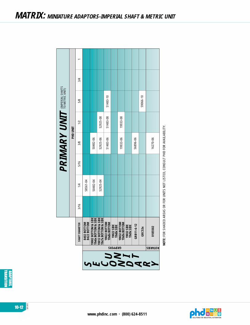
MATRIX: MINIATURE ADAPTORS-IMPERIAL SHAFT & METRIC UNIT
5906
6-10
5148
3-10
5048
2-06
5292
5-06PH
D UN
IT
8402
BOT
TOM
8422
BOT
TOM
GRB1
1-6-
12
GRC5
3x
0185
502
3/8
1/4
3/4
1/2
5/8
SHAF
T DI
AMET
ER
PRIM
ARY
UNIT
S E C O N D A R Y
1900
2 BO
TTOM
& S
IDE
19x6
x BO
TTOM
& S
IDE
NOTE
: FOR
SHA
DED
AREA
S OR
FOR
UNI
TS N
OT L
ISTE
D, C
ONSU
LT P
HD F
OR A
VAIL
ABIL
ITY.
ROTARIESGRIPPERS
(IMPE
RIAL
SHA
FTS
TO M
ETRI
C UN
IT)
3/16
15/
16
5856
1-04
5048
2-04
5292
5-04
5292
5-08
5148
3-06
5148
3-08
1993
3-06
1993
3-08
5689
6-06
1627
0-06
1901
2 BO
TTOM
& S
IDE
19x7
x BO
TTOM
& S
IDE
1902
2 BO
TTOM
19x8
x BO
TTOM
1902
2 SI
DE19
x8x
SIDE
1903
2 BO
TTOM
19x9
x BO
TTOM
1903
2 SI
DE19
x9x
SIDE
U N I T

10-13
www.phdinc.com • (800) 624-8511
CAT-
05
ADAPTORS,
TRANSITION
MATRIX: MINIATURE ADAPTORS-METRIC SHAFT & METRIC UNITS
6183
8-06
5909
3-10
PHD
UNIT
12 m
m8
mm
20 m
m14
mm
16 m
mSH
AFT
DIAM
ETER
PRIM
ARY
UNIT
S E C O N D
1900
2 BO
TTOM
& S
IDE
19x6
x BO
TTOM
& S
IDE
1902
2 BO
TTOM
19x8
x BO
TTOM
NOTE
:FOR
SHA
DED
AREA
S OR
FOR
UNI
TS N
OT L
ISTE
D, C
ONSU
LT P
HD F
OR A
VAIL
ABIL
ITY.
ROTARIESGRIPPERS
RAS5
20
(MET
RIC
SHAF
TSTO
MET
RIC
UNIT
S)
6 m
mM
8 x
1.25
THRE
AD10
mm
6064
3-10
1901
2 BO
TTOM
& S
IDE
19x7
x BO
TTOM
& S
IDE
1902
2 SI
DE19
x8x
SIDE
1903
2 BO
TTOM
19x9
x BO
TTOM
1903
2 SI
DE19
x9x
SIDE
6865
3
6092
8-12
6870
4
U N I T
30 m
m
5846
7
5846
4

www.phdinc.com • (800) 624-8511
CAT-05
ADAPTORS,TRANSITION
10-14
TRANSITION PLATE/ACTUATOR COMBINATIONS
SERIES SAx & SBx, SK & SL,SD & SE SLIDES
SERIES M & C SLIDESSEE REFERENCED PAGESFOR DIMENSIONS,
APPLICATIONS, ANDORDERING DATA.
FOR VARIOUSCOMBINATION EXAMPLES,
SEE PAGE 10-34. SECTION 2 SECTION 2
SECTION 2 10-18 & 10-19
SERIES M & C SLIDES
SERIES SG SLIDES
SECTION 2
SECTION 2
10-28 & 10-29
10-30 & 10-31 10-32 & 10-33
10-30 & 10-31 10-32 & 10-33
PRI
MARY
UNIT
SECONDARY UNIT
SERIES SAx & SBx,SK & SL, SD & SE SLIDES

10-15
www.phdinc.com • (800) 624-8511
CAT-
05
ADAPTORS,
TRANSITION
TRANSITION PLATE/ACTUATOR COMBINATIONS
LARGER GRIPPERS MINIATURE GRIPPERS
SECTION 4 SECTION 4
10-22 & 10-23 10-22, 10-23, 10-34, & 10-35
10-26 & 10-27 10-26 & 10-27
Consult PHD
ROTARY ACTUATORS
SECTION 5
10-20 & 10-21
10-24 & 10-25
10-24 & 10-25
SECONDARY UNIT
10-26 & 10-27

www.phdinc.com • (800) 624-8511
CAT-05
ADAPTORS,TRANSITION
10-16
TRANSITION PLATE MASTER ORDER CODESAll transition plates will be ordered as follows:
When a product is the primary unit, the transition plate will alwaysbe mounted to the moving component of that product (tool plate, saddle,shaft etc.). When a product is a secondary unit, the transition plate willalways be mounted to the stationary component of that product (endblocks, body, housing, etc.).
x x x x x x - x x x x x x - x - xPRIMARY UNIT
SECONDARY UNIT
MOUNTING POSITION
OLDER GRIPPERSSeries 8600 Grippers use the four-digitmodel number as the transition plate code(8624, etc.).
For Series 15000 & 19000 Grippers, use lastfour digits in the five-digit base model numberand omit the “1” at the beginning (15350 =5350, 15351 = 5351, etc.).
NOTE:1) Travel must be specified when SG, SM
or other slide units are secondary unitsthat are being mounted to the end blocksor travel related mounting pattern.Example: S02500 = 2.500 travel
S12500 = 12.500 travel
OLDER ROTARY ACTUATORSSERIES1-20003-40005-60007-8000018x50018x75RAx20RAx25RAx32RAx40RAx50RLx12RLx16RLx20RLx25RLx32RLx40RLx50RLx63
IMPERIALR200R400R600R800R050R075
RAS120RAS125RAS132RAS140RAS150RLS112RLS116RLS120RLS125RLS132RLS140RLS150RLS163
METRICR205R405R605R805RE50RE75
RAS520RAS525RAS532RAS540RAS550RLS512RLS516RLS520RLS525RLS532RLS540RLS550RLS563
OLDER SLIDES
OPTIONSTravel = -Sxxxxx(See Note 1 Below)
SERIESSDx22SDx23SDx24SDx25SDx26SEx22SEx23SEx24SEx25SEx26SGxx1SGxx2SGxx3SGxx4SGxx5SGxx6SKx71SKx72SKx73SKx74SKx75SKx76SLx71SLx72SLx73SLx74SLx75SLx76
IMPERIALSD22SD23SD24SD25SD26SE22SE23SE24SE25SE26SG11SG12SG13SG14SG15SG16
————————————
METRIC——————————
SG51SG52SG53SG54SG55SG56SK71SK72SK73SK74SK75SK76SL71SL72SL73SL74SL75SL76
GRIPPERSSERIES
GRBx2x-1GRBx3x-1GRBx4x-1GRBx5x-1GRBx6x-1GRBx7x-1
GRB11-x-12GRB11-x-16GRB11-x-20GRB11-x-32GRB11-x-40GRB11-x-50
IMPERIALGRB121GRB131GRB141GRB151GRB161GRB171GRB121GRB131GRB141GRB151GRB161GRB171
METRICGRB521GRB531GRB541GRB551GRB561GRB571GRB521GRB531GRB541GRB551GRB561GRB571
CTSSERIESCTSxx12CTSxx16CTSxx20CTSxx32CTSxx40CTSxx50CTSxx63
IMPERIALCTS112CTS116CTS120CTS132CTS140CTS150CTS163
METRICCTS512CTS516CTS520CTS532CTS540CTS550CTS563

10-17
www.phdinc.com • (800) 624-8511
CAT-
05
ADAPTORS,
TRANSITION
TRANSITION PLATE MASTER ORDER CODESALL NEW PRODUCTS
Transition plates codes for all future products or products notshown in previous charts where the size and design number areincorporated in the model number will use the base model numberas their order code. (GRC, GRD grippers, RIS, etc.)
Example:
G R C x 3 x
ORDER CODE = GRCx3x
2 x x x- -
R I S 1 2 5
ORDER CODE = RIS125
1 8 0x3 - x 9 0 - N B
Transition plates codes for all future products or products notshown in previous chart where the size and design number are notincorporated in the model number and are a separate call out willuse the base model number, design, and size as their order code(GRW, GRL, etc...)
Example:
G R W 1 3
ORDER CODE = GRW13116
L 1 1x -
G R L 1 2
ORDER CODE = GRL12114
1 1 4-
- 1 - 1 6 2 0 U B- 9 9
- x 1 3 - L 1 1
RASxxx units can be used as a primary unit if the Q10 andQ19 options are ordered with the unit.

www.phdinc.com • (800) 624-8511
CAT-05
ADAPTORS,TRANSITION
10-18
ORDERING DATA
TRANSITION PLATES: CANTILEVER TYPE & CANTILEVER TYPE
COMBINATIONS FOR SERIES SxL & SxH,SK & SL, SD & SE, STP AND SCV SLIDES
TO ORDER SPECIFY:Primary Unit Number, Secondary UnitNumber and Mounting Position.
1) These numbers apply regardless of unit travel.2) All required mounting hardware is included with the
Transition Plate.3) SD and SE Slides as secondary units positions 3 and
4 require -GV option4) SxL/SxH, SCV, and STP Slides as secondary units are
available in positions 1 and 2 only5) If dowel pin holes are required, consult PHD.
2S -
SECONDARY UNIT
Unit Number
-D 2 4 S D 2 1
PRIMARY UNIT
Unit Number
MOUNTING POSITION
See this page for reference.
NOTES:
PRIMARY UNIT
TRANSITION PLATE
SECONDARY UNIT
4
3
2
1
4
3
2
1
MOUNTING POSITIONSeries SHP, SJP, SIP Slides only
CL
CL
NOTES:1) Use shaded view to find correct
mounting position.2) All units centered on mounting hole
pattern of housing and tool plate.3) STP Slides as secondary units mounted
on transition plate are centered on first4 hole pattern on slide body. (see figure 1)
4) SD, SE, SK & SL Slides as secondaryunits in positions 1 and 2 are always“centered” on the thru and counterboredmounting hole pattern. (see figure 2)
5) SD & SE Slides as secondary units in positions 3 and 4 will be “centered” on the -GV Option mounting hole pattern.(see figure 3)
6) SK/SL Slides as secondary units in positions 3 and 4 are “centered” on side mounting pattern in position 2 on unit.(see figure 3)
SECONDARY UNITPRIMARY UNIT
1
4
3
2
MOUNTINGPOSITIONS
FIGURE 1See Note 3
FIGURE 2See Note 4
FIGURE 3See Notes 5 & 6

10-19
www.phdinc.com • (800) 624-8511
CAT-
05
ADAPTORS,
TRANSITION
POSSIBLE COMBINATIONS: SLIDE & SLIDE
UNIT
NO.
12
3=
[7.9
]=
[9.5
]=
[12.
7]=
.625
= .7
50=
1.25
0=
[15.
9]=
[19]
= [3
1.8]
45
6=
.312
= .3
75=
.500
*
P R I M A R Y U N I T
SERI
ESSB
xSL
IDES
SERI
ESSD
& S
ESL
IDES
SAx1
08[S
Ax50
8]SB
x108
[SBx
508]
SAx1
10[S
Ax51
0]SB
x110
[SBx
510]
SAx1
14[S
Ax51
4]SB
x114
[SBx
514]
SAx1
20[S
Ax52
0]SB
x120
[SBx
520]
SBx1
08[S
Bx50
8]
SBx1
10[S
Bx51
0]
SBx1
14[S
Bx51
4]
SBx1
20[S
Bx52
0]
SBx1
32[S
Bx53
2]
SD22
SE22
SD23
SE23
SD24
SE24
SD25
SE25
SD26
SE26
SAx1
32[S
Ax53
2]SB
x132
[SBx
532]
SD22
SE22
SD23
SE23
SD24
SE24
SD25
SE25
SD26
SE26
SERI
ESSK
& S
LSL
IDES
SK71
SL71
SK72
SL72
SK73
SL73
SK74
SL74
SK75
SL75
SK76
SL76
SK71
SL71
SK72
SL72
SK73
SL73
SK74
SL74
SK75
SL75
SK76
SL76
SERI
ESSC
VSL
IDES
SCV1
2[S
CV52
]
SCV1
3[S
CV53
]
SCV1
4[S
CV54
]
SCV1
5[S
CV55
]
SCV1
6[S
CV56
]
SCV1
7[S
CV57
]
SCV1
8[S
CV58
]
SCV1
9[S
CV59
]
SCVx
12[S
CV52
]SC
Vx13
[SCV
53]
SCVx
14[S
CV54
]SC
Vx15
[SCV
55]
SCVx
16[S
CV56
]SC
Vx17
[SCV
57]
SCVx
18[S
CV58
]SC
Vx19
[SCV
59]
SLID
ES (S
ee N
otes
)
SECO
NDAR
Y UN
IT
STP1
08[S
TP50
8]ST
P116
[STP
516]
STP1
25[S
TP52
0]ST
P120
[STP
520]
STP1
12[S
TP51
2]SH
P108
[SHP
508]
SHP1
12[S
HP51
2]SH
P116
[SHP
516]
SIP5
12SI
P516
SIP5
20SJ
P508
SJP5
12SJ
P516
2 22
2 22 2
2 22
22
222
33
33
33
33
33
3
33
33
33
33
33
33
3
33
33
33
33
33
33
33
33
3 3
3
PLAT
E TH
ICKN
ESS
KEY
33
3
33
33
33
33
33
33
3
33
33
33
33
33
33
33
33
3 3
3
55
55
55
55
5
33
33
33
33
3
33
33
33
33
3*
55
55
5
22
222 33
33 3
33
3 33
33
33
3 3
3
5
2 3 3 4 5 5 6 66 6
6 66 6
6 66 6
6 66 6
55
554
5 55 5
5 5
44
4
3 33 3
2
6 6554
6 655
6 655
6 6
3 3 33 3
52 2 3 3 3
3 3 35 55
33 3 3 5
3 3 3 55 5 6 655
655454
6 655
6 655
6 655
6 656 6
6
4433 5
3 53 5
4 55 5
5
43
33
33
3333
35
43
33
43
333
33
33
33 3 3 3 3 3 3 5 6554
3 3 3 2 2 3 3 3 33 3 3 5 54
2 32 3 3 5322 3 3 33 3 5 5 555332 3
3 3 33 32 25 3 3 3 5 5 55533 3
22
22
3 33
33
33
33
3
3 3 5 3 3 3 5 5533 5 5
33 3 25 3 3 3 5 5 55533 3
3 3 5 3 3 3 5 5533 5 5
3 5 3 3 5 553 5 5
2 32 3 3 53 33 3 5 5 555332 3
3 3 5 3 3 3 5 5533 5 5
33 3 25 3 3 3 5 5 55533 3
NOTE
S:1)
SHA
DED
AREA
S - C
ONSU
LT P
HD F
OR A
VAIL
ABIL
ITY
2) M
ETRI
C NU
MBE
RS A
RE IN
[ ]
3)
=
POSI
TION
1 &
2 =
3, P
OSIT
ION
3 &
4 =
54)
MOD
EL N
UMBE
RS IN
CHA
RT A
RE F
OR R
EFER
ENCE
SEE
CODE
CHA
RT F
OR A
CTUA
L OR
DER
CODE

10-20
www.phdinc.com • (800) 624-8511
CAT-05
ADAPTORS,TRANSITION
ORDERING DATA
TRANSITION PLATES: CANTILEVER TYPE & ROTARY ACTUATOR
COMBINATIONS OF ROTARY ACTUATORS TOSERIES SBx, SK & SL, SD & SE, AND SCV SLIDES
PRIMARY UNIT
TRANSITION PLATE
SECONDARY UNIT 4
3
2
1
MOUNTING POSITION
SECONDARY UNITPRIMARY UNIT
NOTES:1) Use shaded view to find correct mounting position.2) All units are centered on mounting hole pattern of
body and tool plate.
4
3
2
1
MOUNTINGPOSITIONS
CL
CL
TO ORDER SPECIFY:Primary Unit Number, Secondary UnitNumber, and Mounting Position.
1) These numbers apply regardless of unit travel and rotation.2) All required mounting hardware is included with the Transition Plate.3) RLS shafts are not centered with the mounting hole pattern of the
body. (See section 5 for shaft offset dimensions.) Consult PHD ifshafts are required to be centered with tool plate or housingmounting patterns.
4) For RLS units as secondary units in positions 3 & 4, the -GX optionmust be specified on the RLS unit.
5) RIx Rotaries as secondary units are available in position 3 & 4 only.6) If dowel pin holes are required, consult PHD.
1S -
SECONDARY UNIT
Unit Number
-D 2 4 R A S 1
PRIMARY UNIT
Unit Number
MOUNTING POSITION
See this page for reference.
NOTES:
1 2

10-21
www.phdinc.com • (800) 624-8511
CAT-
05
ADAPTORS,
TRANSITION
POSSIBLE COMBINATIONS: SLIDE & ROTARY ACTUATOR
PLATE THICKNESS KEY
33 3333 333 65 5
5 5
33
333333
3
33 5 53 5 53 5 5
2
33
333333
33
333333
33
333333
33
333333
3
3333
333
555 5
UNITNO.
333 333 65 5
5 5
33333
33 5 53 5 53 5 5
33333
33333
33333
33333
3333
555
555 5
5 65 5 5 5 5 5 5 5 5 5 5 5 5 5
55
4 45 55 56 66 6
45566 5 6 6
5 655
5
5 6
6 6 6 666 6 6
55
4
5 56 66 6 6 6
33
3
33335333
35
3
33
35
333
55
333
55
5
33
53
3
35
3
3
5 5
33333
3
333
33 3
2223
3333333
333333
333
33333
5333335
2233
2333
3335
3355
1 2 3= [7.9] = [9.5] = [12.7]= .625 = .750 = 1.250= [15.9] = [19] = [31.8]4 5 6= .312 = .375 = .500
NOTES:1) SHADED AREAS – CONSULT PHD FOR AVAILABILITY2) METRIC NUMBERS ARE IN [ ]3) RLS SHAFTS ARE NOT CENTERED ON ITS MOUNTING HOLE PATTERN.4) MODEL NUMBERS IN CHART ARE FOR REFERENCE. SEE CODE CHART
FOR ACTUAL ORDER CODE
PRIMARY
UNIT
SERIESSBx
SLIDES
SERIESSD & SESLIDES
ROTARY ACTUATORSSECONDARY UNIT
R200[R205]
R400[R405]
SBx110[SBx510]
SBx114[SBx514]
SBx120[SBx520]
SBx132[SBx532]
SD22SE22
SD23SE23
SD24SE24
SD25SE25
SD26SE26
R600[R605]
R800[R805]
RAS120[RAS520]RAS125
[RAS525]
RAS132[RAS532]
RAS140[RAS540]
RAS150[RAS550]
RLS112[RLS512]
RLS116[RLS516]
RLS120[RLS520]
RLS125[RLS525]
RLS132[RLS532]
RLS140[RLS540]
RLS150[RLS550]
RLS163[RLS563]
SK71SL71
SK72SL72
SK73SL73
SK74SL74
SK75SL75
SERIESSK & SLSLIDES
SK76SL76
SERIESSCV
SLIDES
SCVx12[SCV52]
SCVx13[SCV53]
SCVx14[SCV54]
SCVx15[SCV55]
SCVx16[SCV56]
SCVx17[SCV57]
SCVx18[SCV58]
SCVx19[SCV59]
RIx25 RIx32 RIx50
SBx108[SBx508]
RFS114[RFS514]
RFS120[RFS520]
RFS125[RFS525] RCx08 RCx12 RCx16
10-22
www.phdinc.com • (800) 624-8511
CAT-05
ADAPTORS,TRANSITION
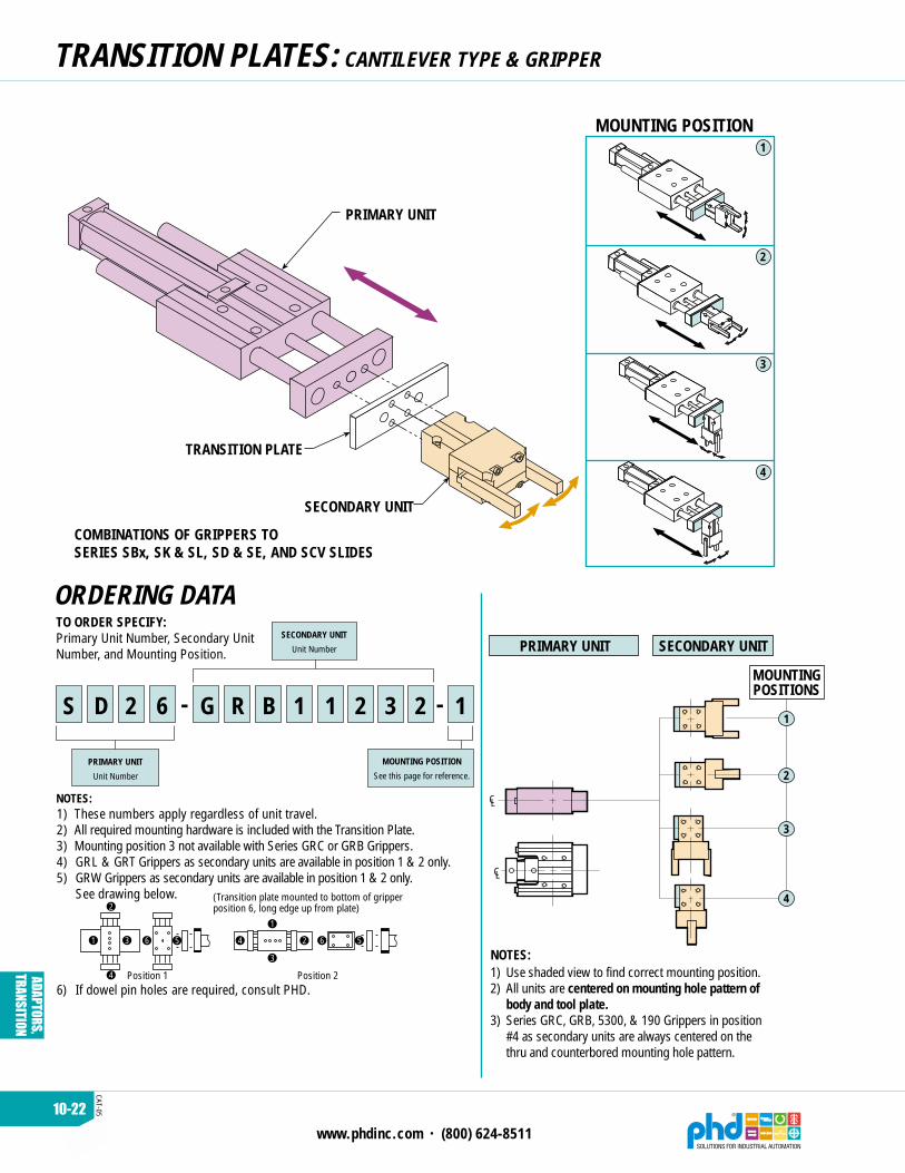
ORDERING DATA
TRANSITION PLATES: CANTILEVER TYPE & GRIPPER
COMBINATIONS OF GRIPPERS TOSERIES SBx, SK & SL, SD & SE, AND SCV SLIDES
PRIMARY UNIT
TRANSITION PLATE
SECONDARY UNIT
4
3
2
1
MOUNTING POSITION
1) These numbers apply regardless of unit travel.2) All required mounting hardware is included with the Transition Plate.3) Mounting position 3 not available with Series GRC or GRB Grippers.4) GRL & GRT Grippers as secondary units are available in position 1 & 2 only.5) GRW Grippers as secondary units are available in position 1 & 2 only.
See drawing below.
6) If dowel pin holes are required, consult PHD.
TO ORDER SPECIFY:Primary Unit Number, Secondary UnitNumber, and Mounting Position.
1S -
SECONDARY UNIT
Unit Number
-D 2 6 G R B 1
PRIMARY UNIT
Unit Number
MOUNTING POSITION
See this page for reference.
NOTES:
1 2
531
2
4
6 4 2
3
1
56
Position 1 Position 2
3 2
(Transition plate mounted to bottom of gripperposition 6, long edge up from plate)
PRIMARY UNIT
MOUNTINGPOSITIONS
SECONDARY UNIT
NOTES:1) Use shaded view to find correct mounting position.2) All units are centered on mounting hole pattern of
body and tool plate.3) Series GRC, GRB, 5300, & 190 Grippers in position
#4 as secondary units are always centered on thethru and counterbored mounting hole pattern.
CL
CL
1
4
3
2

10-23
ww
w.phdinc.com
• (800) 624-8511
CAT-05
ADAPTORS,TRANSITION
POSSIBLE COMBINATIONS: SLIDE &
GRIPPER
3333335223335
335555
33
335
3335
35555
33
335
335
5555
35
35
555
1 2 3= [7.9] = [9.5] = [12.7]= .625 = .750 = 1.250= [15.9] = [19] = [31.8]4 5 6= .312 = .375 = .500
NOTES:1) SHADED AREAS – CONSULT PHD FOR AVAILABILITY2) METRIC NUMBERS ARE IN [ ]3) MODEL NUMBERS IN CHART ARE FOR REFERENCE, SEE CODE CHART
FOR ACTUAL ORDER CODE
SBx110[SBx510]
SBx114[SBx514]
SBx120[SBx520]
SBx132[SBx532]
SD22SE22
SD23SE23
SD24SE24
SD25SE25
SD26SE26
SBx108[SBx508]
UNITNO.
PRIMARY
UNIT
SERIESSBx
SLIDES
SERIESSD & SESLIDES
GRIPPERSSECONDARY UNIT
SERIESSK & SLSLIDES
8400 8410 8420 84309x6x9x6x9x6x
9x7x9x7x9x7x
9x8x9x8x9x8x
9x9x9x9x9x9x
GRB1
1x12
112232233322233323345566
PLATE THICKNESS KEY
222232233322233323345566
22233333333333323345566
333333333333323345566
122232233322233323345566
2222322333222333
3345566
2
2323333333333
45566
2333333333333
5566
333333333333333333345566
3333333333333333
3345566
3333333333333333
45566
33
3333
33333
66
5
555
555
6
55
55
33
3333
33333
566
3
333
333
6
55
55
5
5
SK71SL71
SK72SL72
SK73SL73
SK74SL74
SK75SL75
SK76SL76
GRDx3x GRDx6xGRDx4x GRDx5x
1122322333222333
345566
2222322333222333
45566
222333333333333
66
3333333333333
6
GRB1
1x16
GRB1
1x20
GRB1
1x32
GRB1
1x40
GRB1
1x50
GRCx
3x
GRCx
4x
GRCx
5x
GRCx
6x
GRTx1 GRTx2 GRTx3 GRTx4 GRTx5 GRTx6 GRTx7 GRTx8
GRLx
14
GRLx
16
GRW
16
GRW
25
GRW
32
GRW
40
GRW
50
SERIESSCV
SLIDES
SCV12[SCV52]
SCV13[SCV53]SCV14
[SCV54]
SCV15[SCV55]
SCV16[SCV56]SCV17
[SCV57]
SCV18[SCV58]SCV19
[SCV59]
223332223522223322235555
333333333533333333335555
33333333533333333335555
55
5555
55555
5555555
353333533333533335555
55
555
5555
55555
5
555
555
555
5
555
55
55
55
55
22335
222
22335
222
333353333533333533335555
33355555555
55555
5555
5555
5555
555
55
555
GRSx27 GRSx28 GRSx32 GRSx50 GRSx63
33
3335
3333533335555
3
3335
333533335555
335
335
35555
55
55
555
5
55
55
GRFx
xx19
GRFx
xx25
GRFx
xx28
GRFx
xx32

10-24
www.phdinc.com • (800) 624-8511
CAT-05
ADAPTORS,TRANSITION
ORDERING DATA
TRANSITION PLATES: SADDLE TYPE & ROTARY ACTUATOR
COMBINATIONS OF ROTARY ACTUATORSTO SERIES SG, SM, & SFP SLIDES
PRIMARY UNIT
TRANSITION PLATE
SECONDARY UNIT
2
1
MOUNTING POSITION
PRIMARY UNIT SECONDARY UNIT
MOUNTINGPOSITIONS
CL
CL
NOTES:1) Use shaded view to find correct mounting position.2) On Series SG, Rotary Actuator tube may interfere with cylinder
port (in Position 1 only) in retracted position.3) All units are centered on mounting hole pattern of body and
saddle.
NOTE TUBE POSITIONTRANSITION PLATE
Y
X
THRU HOLES(REFERENCE)
2
1
TO ORDER SPECIFY:Primary Unit Number, Secondary UnitNumber, and Mounting Position.
1) These numbers apply regardless of unit travel and rotation.2) All required mounting hardware is included with the Transition Plate.3) RLS shafts are not centered with the mounting hole pattern.
(See section 5 for shaft offset dimensions.) Consult PHD ifshafts are required to be centered with tool plate or housingmounting patterns.
4) For RLS units as secondary unit in positions 1 & 2, the -GX optionmust be specified on the RLS unit.
5) If dowel pin holes are required, consult PHD.
1S -
SECONDARY UNIT
Unit Number
-G 2 5 R A S 1
PRIMARY UNIT
Unit Number
MOUNTING POSITION
See this page for reference.
NOTES:
3 2

10-25
ww
w.phdinc.com
• (800) 624-8511
CAT-05
ADAPTORS,TRANSITION
POSSIBLE COMBINATIONS: SADDLE TYPE & ROTARY ACTUATOR
UNITNO.
RAS125[RAS525]
NOTES:1) SHADED AREAS – CONSULT PHD FOR AVAILABILITY2) METRIC NUMBERS ARE IN [ ]3) RLS SHAFTS ARE NOT CENTERED ON ITS MOUNTING HOLE PATTERN.4) MODEL NUMBERS IN CHART ARE FOR REFERENCE, SEE CODE CHART
FOR ACTUAL ORDER CODE
*
*
*
*
*
*
*
*
*
*
*
*
*
*
*
*
*
*
*
*
*
*
*
*
*
*
*
*
*
*
*
*
*
*
*
*
*
*
*
*
4455
33597
455
597
55
77
66
8
334455
333597
334455
33597
334455
3597
34455
3597
4455
567
3344552333597
3344552333597
334455
333597
334455
33597
334455
3597
34455
3597
5555
597
5555
97
55
33567
6
35
108
5108
3333
3335
33335
3355
33355
3555
3333
2333
3333
33353
33355
3353
PLATE THICKNESS KEY
12345
6789
10* = Numbers indicate the total thickness of two
plates, required due to design reasonsExample:9* = 1.000 total thickness of two .500 plates
SG21[SG61]
SERIESSG
SLIDES
SG22[SG62]
SG23[SG63]
SG24[SG64]
SG25[SG65]
SG26[SG66]
PRI
MARY
UNIT
ROTARY ACTUATORSSECONDARY UNIT
R200[R205]
R400[R405]
R600[R605]
R800[R805]
RAS120[RAS520]
RAS132[RAS532]
RAS140[RAS540]
RAS150[RAS550]
RLS112[RLS512]
RLS116[RLS516]
RLS120[RLS520]
RLS125[RLS525]
RLS132[RLS532]
RLS140[RLS540]
RLS150[RLS550]
RLS163[RLS563] RIx25 RIx32 RIx50 RFS114
[RFS514]RFS120
[RFS520]RFS125
[RFS525]
SM108[SM508]
SM112[SM512]
SM116[SM516]
SM125[SM525]
SM132[SM532]
SERIESSM
SLIDES
SERIESSFP
SLIDES
SFP527
SFP540
RCCx112[RCCx512]
RCCx116[RCCx516]
RCCx108[RCCx508]
= .313 [7.9]
= .375 [9.5]
= .500 [12.7]
= .625 [15.9]
= .750 [19.0]
= 1.250 [31.8]
= 1.500 [38.1]
= 2.000 [50.8]
= 1.000 [25.4]
= 1.750 [44.5]
Becky
Becky

10-26
www.phdinc.com • (800) 624-8511
CAT-05
ADAPTORS,TRANSITION
ORDERING DATA
TRANSITION PLATES: SADDLE TYPE & GRIPPER
COMBINATIONS OF GRIPPERS TO SLIDES
2
1
TRANSITION PLATE
SECONDARY UNIT
PRIMARY UNIT
MOUNTING POSITION
TO ORDER SPECIFY:Primary Unit Number, Secondary UnitNumber, and Mounting Position.
1) These numbers apply regardless of unit travel.2) All required mounting hardware is included with the
Transition Plate.3) GRW Grippers as secondary units, see drawing below.
4) If dowel pin holes are required, consult PHD.
1S -
SECONDARY UNIT
Unit Number
-G 2 5 G R B 1
PRIMARY UNIT
Unit Number
MOUNTING POSITION
See this page for reference.
NOTES:
1 2 3 2
4 2
3
1
56
Position 1
531
2
4
6
Position 2
(Transition plate mounted to bottom of gripperposition 6, long edge up from plate)
PRIMARY UNIT SECONDARY UNIT
MOUNTINGPOSITIONS
CL
CL
NOTES:1) Use shaded view to find correct mounting position.2) All units are centered on mounting hole pattern of
body and saddle.
YTHRU MOUNTING
HOLES (REFERENCE)
X
NOTE JAW POSITION
TRANSITION PLATE
2
1

10-27
www.phdinc.com • (800) 624-8511
CAT-
05
ADAPTORS,
TRANSITION
POSSIBLE COMBINATIONS: SLIDE & GRIPPER
UNITNO.
UNITNO.
NOTES:1) SHADED AREAS – CONSULT PHD FOR AVAILABILITY2) METRIC NUMBERS ARE IN [ ]3) MODEL NUMBERS IN CHART ARE FOR REFERENCE, SEE CODE CHART
FOR ACTUAL ORDER CODE
PLATE THICKNESS KEY
12345
6789
10* = Numbers indicate the total thickness of two
plates, required due to design reasonsExample:9* = 1.000 total thickness of two .500 plates
223
233359
2233
233359
2233
33597
2233
3597
223
233359
2233
233359
2233
33597
333
3597
2233
33597
23334
3597
23334
3597
33345
577
445
33597
33334
3597
33345
3597
3445
7
223
2333597
2233
2333597
2233
333597
2233
3597
3333597
77
33355
333597
3355
33597
355
35
7
55
35
2222352333597
333335
333597
333335
33597
555555
3597
55
5
5
5
55
5
33359
333335
333597
333335
33597
555555
35
7
555
35
55
5
333355
333597
33355
3597
555
35
7
233359
355
5
7
55
5
7
**
**
* * **
**
**
**
**
**
**
**
**
**
**
**
**
**
**
**
**
**
** *
**
**
**
** *
* * **
** *
**
** * *
SERIESSG
SLIDESPRI
MARY
UNIT
SG21[SG61]
SG22[SG62]
SG23[SG63]
SG24[SG64]
SG25[SG65]
SG26[SG66]
SERIESSM
SLIDES
SM108[SM508]
SM112[SM512]
SM116[SM516]
SM125[SM525]
SM132[SM532]
SERIESSFP
SLIDES
SFP527
SFP540
SERIESSG
SLIDESPRI
MARY
UNIT
SG21[SG61]
SG22[SG62]
SG23[SG63]
SG24[SG64]
SG25[SG65]
SG26[SG66]
SERIESSM
SLIDES
SM108[SM508]
SM112[SM512]
SM116[SM516]
SM125[SM525]
SM132[SM532]
SERIESSFP
SLIDES
SFP527
SFP540
GRIPPERS
SECONDARY UNIT
8400 8410 8420 8430 9x6x 9x7x 9x8x 9x9x
GRBx3x
GRCx5x
GRBx4x
GRBx5x
GRBx6x
GRCx3x
GRCx4x
GRCx6x
GRDx3x
GRDx4x
GRDx5x
GRDx6x
GRBx2x
GRBx7x
GRIPPERS
SECONDARY UNIT
GRTx5
GRWx25
GRTx6
GRTx7
GRTx8
GRLx16
GRWx16
GRWx32
GRWx40
GRWx50
GRFxxx19
GRFxxx25
GRTx4
GRLx14
GRSx28
GRSx32
GRSx50
GRSx63
GRTx2
GRTx3
GRSx27
GRTx1
GRFxxx28
GRFxxx32
GRRx50
= .313 [7.9]
= .375 [9.5]
= .500 [12.7]
= .625 [15.9]
= .750 [19.0]
= 1.250 [31.8]
= 1.500 [38.1]
= 2.000 [50.8]
= 1.000 [25.4]
= 1.750 [44.5]
Becky
Becky
Becky

10-28
www.phdinc.com • (800) 624-8511
CAT-05
ADAPTORS,TRANSITION
ORDERING DATA
TRANSITION PLATES: CANTILEVER TYPE & SADDLE SLIDE
COMBINATIONS OF SERIES SM TOSERIES SBx, SD & SE, SK & SL, AND SCV SLIDES
2
1
TRANSITION PLATE
PRIMARY UNIT
SECONDARY UNIT
MOUNTING POSITION
PRIMARY UNIT SECONDARY UNIT
MOUNTINGPOSITIONS
NOTES:1) Use shaded view to find correct mounting position.2) All units are centered on mounting hole pattern of
end blocks and tool plate.
TRANSITION PLATE
CL
CL
2
1
TO ORDER SPECIFY:Primary Unit Number, Secondary UnitNumber, and Mounting Position.
1) These numbers apply regardless of unit travel and rotation.2) All required mounting hardware is included with the
Transition Plate.3) When a Series SM Slide is the secondary unit, the travel must
be specified when ordered. (6-Digit long code after standardcall out is required with assumed decimal points 3 places from right)Example: S02000 = 2.000 Travel
S03500 = 3.500 TravelOption -S_ _ _ _ _ stroke required for SM Slides assecondary unit.
4) If dowel pin holes are required, consult PHD.
1S -
SECONDARY UNIT
Unit Number
-D 2 6 S M B 2
PRIMARY UNIT
Unit Number
MOUNTING POSITION
See this page for reference.
NOTES:
- SSee note 3
80

10-29
www.phdinc.com • (800) 624-8511
CAT-
05
ADAPTORS,
TRANSITION
POSSIBLE COMBINATIONS: SLIDE & SLIDE
UNITNO.
NOTES:1) SHADED AREAS – CONSULT PHD FOR AVAILABILITY2) METRIC NUMBERS ARE IN [ ]3) MODEL NUMBERS IN CHART ARE FOR REFERENCE, SEE CODE CHART
FOR ACTUAL ORDER CODE
1 2 3= [7.9] = [9.5] = [12.7]= .625 = .750 = 1.250= [15.9] = [19] = [31.8]4 5 6= .312 = .375 = .500
PLATE THICKNESS KEY
PRIMARY
UNIT
SERIESSBx
SLIDES
SERIESSD & SESLIDES
SLIDESSECONDARY UNIT
SBx114[SBx514]
SBx120[SBx520]
SBx132[SBx532]
SD22[SE22]
SD23[SE23]
SD24[SE24]
SD25[SE25]
SD26[SE26]
SK75SL75
SK76SL76
SK71SL71
SK72SL72
SK73SL73
SK74SL74
SERIESSK & SLSLIDES
SERIESSCV
SLIDES
SCV12SCV52
SCV13SCV53
SCV14SCV54
SCV15SCV55
SCV16SCV56
SCV17SCV57
SCV18SCV58
SCV19SCV59
SBx108[SBx508]
SBx110[SBx510]
SM108[SM508]
SM112[SM512]
SM116[SM516]
SM125[SM525]
SM132[SM532]
233
333522333523335555
33
3335
23335
335555
33
3335
33335
35555
3
335
3335
5555
5
555

10-30
www.phdinc.com • (800) 624-8511
CAT-05
ADAPTORS,TRANSITION
ORDERING DATA
TRANSITION PLATES: SADDLE TYPE & CANTILEVER SLIDE
COMBINATIONS OF SERIES SAx & SBx, SD & SE,SK & SL, SHP, SIP, SJP, STP, AND SCV TO SERIES SG AND SM SLIDES
MOUNTING POSITION
TRANSITION PLATE
PRIMARY UNIT
SECONDARY UNIT
Series SHP, SJP, SIP Slides only
2
1
1
2
PRIMARY UNIT SECONDARY UNIT
CL
MOUNTINGPOSITIONS
CL
NOTES:1) Use shaded view to find correct mounting position.2) *Unless otherwise specified, the front edge of the secondary unit bearing housing is flush with the primary slide saddle side.
X
Y TRANSITION PLATEREFERENCE
SEE NOTE #2*
THRU HOLES(REFERENCE)
2
1
TO ORDER SPECIFY:Primary Unit Number, Secondary UnitNumber, and Mounting Position.
1) These numbers apply regardless of unit travel.2) All required mounting hardware is included with the
Transition Plate.3) SD/SE Slides as secondary units in position 2 require
-GV option.4) STP, SAx, & SBx Slides are not available in position 2.5)If dowel pin holes are required, consult PHD.
4S -
SECONDARY UNIT
Unit Number
-G 2 5 S D 2 1
PRIMARY UNIT
Unit Number
MOUNTING POSITION
See this page for reference.
NOTES:

10-31
ww
w.phdinc.com
• (800) 624-8511
CAT-05
ADAPTORS,TRANSITION
POSSIBLE COMBINATIONS: SLIDE &
SLIDE
PLATE THICKNESS KEY
12345
6789
10* = Numbers indicate the total thickness of two
plates, required due to design reasonsExample:9* = 1.000 total thickness of two .500 plates
= .313 [7.9]
= .375 [9.5]
= .500 [12.7]
= .625 [15.9]
= .750 [19.0]
= 1.250 [31.8]
= 1.500 [38.1]
= 2.000 [50.8]
= 1.000 [25.4]
= 1.750 [44.5]
UNITNO.
SG21[SG61]
SG22[SG62]
SG23[SG63]
SG24[SG64]
SG25[SG65]
SG26[SG66]
SM108[SM508]
SM112[SM512]
SM116[SM516]
SM125[SM525]
SM132[SM532]
SFP527
SFP540
NOTES:1) SHADED AREAS – CONSULT PHD FOR AVAILABILITY2) METRIC NUMBERS ARE IN [ ]3) MODEL NUMBERS IN CHART ARE FOR REFERENCE, SEE CODE CHART
FOR ACTUAL ORDER CODE
SFP527
SFP540
333455233353
333455
3353
333455
3535
4455
3535
333455
3353597
334455
3353597
4455
353597
455
53597
455
535
55
55577
333455
3353597
333455
353597
3455
355577
455
5
5
7
455
33353597
55
33552333535
355
33535
55
3535
333455
33353
333455
33535
444455
5555
55555
55
5
5555
5
666
5
66 6
333355233359
3
333355
33359
3
333355
3359
3
333355
33359
3
333355
359
3
333355233359
3
333355
33359
3
333355
3359
3
355
333535
55
3535
333355
3359
3**
**
**
**
**
**
**
**
** *
* * * * * * * * * * * * * * * * *
SAx108[SAx108]SBx108[SBx108]
SAx110[SAx110]SBx110[SBx110]
SAx114[SAx114]SBx114[SBx114]
SAx120[SAx120]SBx120[SBx120]
SAx132[SAx132]SBx132[SBx132]
SD22SE22
SD23SE23
SD24SE24
SD25SE25
SERIESSG
SLIDES
PRI
MARY
UNIT
SK71SL71
SK72SL72
SK73SL73
SK74SL74
SK75SL75
SK76SL76
SD26SE26
SCVx
12[S
CV52
]
SCVx
13[S
CV53
]
SCVx
14[S
CV54
]
SCVx
15[S
CV55
]
SCVx
16[S
CV56
]
SCVx
17[S
CV57
]
SCVx
18[S
CV58
]
SCVx
19[S
CV59
]
SHP1
08SH
P508
SHP1
12SH
P512
SHP1
16SH
P516
SERIESSM
SLIDES
SIP5
12
SIP5
16
SIP5
20
SJP5
08
SJP5
12
SJP5
16
STP1
08ST
P508
STP1
12ST
P512
STP1
16ST
P516
STP1
20ST
P520
STP1
25ST
P525
SERIES SFPSLIDES
Position #1
SERIES SFPSLIDES
Position #2
SLIDESSECONDARY UNIT
Becky
Becky

10-32
www.phdinc.com • (800) 624-8511
CAT-05
ADAPTORS,TRANSITION
ORDERING DATA
TRANSITION PLATES: SADDLE TYPE & SADDLE TYPE
COMBINATIONS OF SERIES SG, SM, & SFP SLIDES
PRIMARY UNIT
TRANSITION PLATE
SECONDARY UNIT
MOUNTING POSITION
2
1
PRIMARY UNIT SECONDARY UNIT
MOUNTINGPOSITIONS
NOTES:1) Use shaded view to find correct mounting position.2) All units are centered on mounting hole pattern of
the end blocks and saddle.4) On Series SG & SFP Slides, the secondary unit may
interfere with the cylinder port of the primary unitin position 2.
X
Y
CL
CL
TRANSITION PLATE
THRU HOLES(REFERENCE)
2
1
TO ORDER SPECIFY:Primary Unit Number, Secondary UnitNumber, and Mounting Position.
1) These numbers apply regardless of unit travel.2) All required mounting hardware is included with the
Transition Plate.3) When Series SG & SM Slides are a secondary unit, the
travel must be specified when ordered.(6-Digit long code after standard call out is required withassumed decimal points 3 places from right)Example: S02000 = 2.000 Travel
S03500 = 3.500 TravelOption -S_ _ _ _ _ stroke required for SG and SM Slides
as secondary unit.4) If dowel pin holes are required, consult PHD.
1S -
SECONDARY UNIT
Unit Number
-G 2 5 S M B 1
PRIMARY UNIT
Unit Number
MOUNTING POSITION
See this page for reference.
NOTES:
- SSee note 3
80

10-33
www.phdinc.com • (800) 624-8511
CAT-
05
ADAPTORS,
TRANSITION
POSSIBLE COMBINATIONS: SLIDE & SLIDE
UNITNO.
SG21[SG61]
SG22[SG62]
SG23[SG63]
SG24[SG64]
SG25[SG65]
SG26[SG66]
SM132[SM532]
SG108[SG508]
SG112[SG512]
SG116[SG516]
SG125[SG525]
SG132[SG532]
SFP527
SFP540
55
5
5
NOTES:1) SHADED AREAS – CONSULT PHD FOR AVAILABILITY2) METRIC NUMBERS ARE IN [ ]3) MODEL NUMBERS IN CHART ARE FOR REFERENCE, SEE CODE CHART
FOR ACTUAL ORDER CODE
= .625 = .750 = 1.250= [15.9] = [19] = [31.8]
SERIESSG
SLIDES
PRIMARY
UNIT
SG21[SG61]
SG22[SG62]
SG23[SG63]
SG24[SG64]
SG25[SG65]
SG26[SG66]
SM108[SM508]
SM112[SM512]
SM116[SM516]
SM125[SM525]
SERIESSM
SLIDES
SERIESSFP
SLIDES
SLIDESSECONDARY UNIT
333455
33535
33455
33535
3455
3535
455
535
455
5
55
3333552333535
333355
333535
33355
33535
355
3535
1 2 3= [7.9] = [9.5] = [12.7] 4 5 6= .312 = .375 = .500
PLATE THICKNESS KEY

10-34
www.phdinc.com • (800) 624-8511
CAT-05
ADAPTORS,TRANSITION
COMBINATION EXAMPLES: TRANSITION PLATES
#3
#2
#1
#1
#2
#3
See pages 10-18 & 10-19.
#3
#1
See pages 10-20 & 10-21.
0S -
SECONDARYUNIT
-D 2 4 R 2 0 4
PRIMARYUNIT
MOUNTINGPOSITION
4S -
SECONDARYUNIT
-D 2 6 S D 2 1
PRIMARYUNIT
MOUNTINGPOSITION
HUB ADAPTOR(See pages 10-6 to 10-9 for details.)
#2
2 TRANSITION PLATES1 HUB ADAPTOR USEDOrdering Example:
3 TRANSITION PLATESOrdering Example:
See pages 10-18 & 10-19.
#3
See pages 10-18 & 10-19.
#2
See pages 10-22 & 10-23.
#1
4S -
SECONDARYUNIT
-D 2 6 S D 2 4
PRIMARYUNIT
MOUNTINGPOSITION
1S -
SECONDARYUNIT
-D 2 3 G R B 2
PRIMARYUNIT
MOUNTINGPOSITION
3S -
SECONDARYUNIT
-D 2 4 S D 2 1
PRIMARYUNIT
MOUNTINGPOSITION
12

10-35
www.phdinc.com • (800) 624-8511
CAT-
05
ADAPTORS,
TRANSITION
STANCHION ENGINEERING DATApage 10-40
Bending moments, torque limitations, and shaft deflections.
STANCHION BASE AND SHAFT(S)pages 10-36 & 10-37
Specifications, Ordering Data, and Base Dimensions.
STANCHIONS
MOUNTING PLATE(S) ANDBLOCK(S)pages 10-38 & 10-39
Envelope and mounting hole dimensions for universal plates,blocks, and blank mounting plates listed.
SINGLE DOUBLE
SINGLE DOUBLE

10-36
www.phdinc.com • (800) 624-8511
CAT-05
ADAPTORS,TRANSITION
STANCHIONDOUBLE BASE
ASSEMBLY
STANCHIONSINGLE BASE
ASSEMBLY
MOUNTINGPLATE
MOUNTINGBLOCK
STANCHION BASE ASSEMBLY
To order specify:Model Base, Design No., Shaft(s) Type,and Height.
MOUNTING PLATE AND MOUNTING BLOCKKIT NUMBERS
To order Mounting Plates and Mounting Blocks, specify properkit number.
STANCHIONS
13230 1
DESIGN NO.
MODEL BASE
- - 1 06
HEIGHTTo the top of the shaft(s)
in 1" increments
SHAFT TYPE
1 - Hollow5 - Hollow with Electroless Nickel Plate
-
1" Single Shaft - 132101" Double Shaft - 13220
1-1/2" Single Shaft - 132301-1/2" Double Shaft - 13240
2" Single Shaft - 132502" Double Shaft - 13260
ORDERING DATA: STANCHIONS
SPECIFICATIONS SERIES 132xx
MODELS Single or Double Shafts
SHAFTS 1", 1-1/2", and 2" Dia.
Hollow, Brite Zinc Plated
Available in 1" increments
up to 60 inch Maximum Length
(Consult PHD for longer shaft lengths)
BASE Anodized Aluminum
MOUNTING PLATES Anodized Aluminum
AND BLOCKS
REINFORCEMENT Zinc Plated Steel
SPECIFICATIONS
SHAFT DIA. DESCRIPTION SINGLE # DOUBLE #Blank Mounting Plate 12625-04 12624-04
1 Universal Mounting Plate Kit* 13175 13172Mounting Block Kit* 13181 13178Blank Mounting Plate 12625-05 12624-05
1-1/2 Universal Mounting Plate Kit* 13176 13173Mounting Block Kit* 13182 13179Blank Mounting Plate 12625-06 12624-06
2 Universal Mounting Plate Kit* 13177 13174Mounting Block Kit* 13183 13180
*All mounting holes are predrilled for attaching PHD Slides,Rotary Actuators, and Multi-Motion Actuators. (See individualsections for sizing.)
NOTE:1) All mounting hardware isprovided with each stanchionbase assembly.2) Series 13250, 13260minimum 2” height.
NOTES:1) Mounting blocks, mounting plates, and stanchion base
assemblies must be ordered separately. See below.2) For specific product mounting patterns consult factory.

10-37
www.phdinc.com • (800) 624-8511
CAT-
05
ADAPTORS,
TRANSITION
DIMENSIONS: STANCHION BASES
SHAFTDIA.
LETTER DIMENSION
SINGLEDOUBLESINGLEDOUBLESINGLEDOUBLE
BASETYPE
KITNO.
13210-1-1-xx13220-1-1-xx13230-1-1-xx13240-1-1-xx13250-1-1-xx13260-1-1-xx
A2.8806.3703.8807.7504.7509.500
B C E FD1.5005.0002.2406.1152.7607.510
N/A3.500N/A
3.875N/A
4.750
2.2505.7503.1257.0003.7508.500
1.970
2.450
3.180
.795
1.120
1.465
1.620
2.250
2.750
Q
.500
.620
.750
R
1/4
5/16
3/8
S
.620
.880
1.250
P
.620
.810
1.000
O
.500
.750
1.000
N
2.400
2.900
3.900
M
.687
.875
1.250
L
.280
.380
.440
K
.220
.250
.440
J
1.000
1.375
1.750
HG
.310
.565
.750
EACH STANCHION BASE ASSEMBLY KIT CONTAINS:1 BASE2 REINFORCEMENT PLATESREQUIRED NO. OF SHCSREQUIRED NO. OF SHAFTS (HOLLOW SHAFT IS STANDARD)
HEIGHTORDERED
M
N
P
O
SHAFTDIA
E
F
B
A
K SLOTWIDTH
J
GH
C ± .001
D
L DIATHRU
HEIGHTORDERED
M
N
P
O
SHAFTDIA
.250
H
R
Q
2X THRU HOLEFOR S SHCS
SINGLE STANCHION BASE DOUBLE STANCHION BASE
L DIATHRU
B
AD
K SLOTWIDTH
J
GH
T T
REINFORCEMENT PLATESEE CHART FOR KIT
.750
.880
1.120
T
E
F
1
1-1/2
2
REINFORCEMENTPLATE KIT NO.
12243
12247
12264

10-38
www.phdinc.com • (800) 624-8511
CAT-05
ADAPTORS,TRANSITION
DIMENSIONS: STANCHION MOUNTING PLATES
EACH KIT CONTAINS REQUIRED HARDWARE TO MOUNT TO BASE UNIT AND PHD COMPONENT.
6X THRU HOLEFOR O SCREWS
THRU HOLE FORBASE SHAFT DIA
AP
H
N
ML
G
J
K
2X THRU HOLE FORBASE SHAFT DIA
P
H
N
ML
G
J
K
LETTER DIMENSION
1.200
1.450
1.950
K
3.310
5.120
6.000
HG
1.190
1.380
1.750
DCA
2X E THREAD FROM THIS SIDE
2X F THREAD FROM THIS SIDE
6X THRU HOLE FOR O SCREWS
B ± .001
SINGLEMOUNTING PLATE
DOUBLEMOUNTING PLATE
L
1.060
1.620
2.000
NA
NA
NA
M
1.560
2.620
3.500
NA
NA
NA
N
3.060
4.620
5.500
NA
NA
NA
O
1/4
5/16
3/8
NA
NA
NA
P
1.500
2.000
2.500
NA
NA
NA
J
4.500
6.500
7.750
F
5/16-18 x .70 DP
5/16-18 x .62 DP
3/8-16 x .62 DP
NA
NA
NA
E
5/16-18 x .70 DP
3/8-16 x .62 DP
7/16-14 x .62 DP
NA
NA
NA
D
3.750
4.750
6.250
NA
NA
NA
C
4.750
6.250
7.500
NA
NA
NA
B
3.500
3.875
4.750
A
5.500
7.000
8.500
KITNO.
12624-0413172
12624-0513173
12624-0613174
BLANKUNIVERSAL
BLANKUNIVERSAL
BLANKUNIVERSAL
BASETYPE
SHAFTDIA.
1
1-1/2
2
EACH KIT CONTAINS REQUIRED HARDWARE TO MOUNT TO BASE UNIT AND PHD COMPONENT.
LETTER DIMENSIONL
1.060
1.620
2.000
NA
NA
NA
M
1.560
2.620
3.500
NA
NA
NA
N
3.060
4.620
5.500
NA
NA
NA
O
1/4
5/16
3/8
NA
NA
NA
P
1.500
2.000
2.500
NA
NA
NA
G
1.190
1.380
1.750
A
2.000
3.000
4.000
KITNO.
12625-0413175
12625-0513176
12625-0613177
BLANKUNIVERSAL
BLANKUNIVERSAL
BLANKUNIVERSAL
BASETYPE
SHAFTDIA.
1
1-1/2
2
K
1.200
1.450
1.950
J
4.500
6.500
7.750
H
3.310
5.120
6.000

10-39
www.phdinc.com • (800) 624-8511
CAT-
05
ADAPTORS,
TRANSITION
DIMENSIONS: STANCHION MOUNTING BLOCKS
SINGLEMOUNTING BLOCK
DOUBLEMOUNTING BLOCK
SHAFTDIA.
LETTER DIMENSION
131811318213183
KITNO. A
1.9502.4503.200
B C D.8101.2001.500
2.0002.4503.250
.500
.475
.750
11-1/2
2
E1.0001.5001.750
F.380.475.750
G1.2501.0001.500
H.430.700.750
J.7501.0001.500
K10-24 x .38 DP1/4-20 x .50 DP5/16-18 x .50 DP
L10-24 x .38 DP10-24 x .38 DP1/4-20 x .50 DP
EACH KIT CONTAINS REQUIRED HARDWARE TO MOUNT TO BASE UNIT AND PHD COMPONENT.
F
THRU HOLE FORBASE SHAFT DIA
B
C ± .001
E K
A
HD
H
4X THRU DIA &C'BORE FOR J SHCS
4X THRU DIAFOR J SCREW
C
3/8-16 x 1.00 DP THREAD2.500 SQ MTG HOLE PATTERNHOLE PATTERN IS ON PART NO. 13183 ONLY
4X K THREAD
D
E SQ
F
G
4X L THREAD
H J
THRU HOLE FORBASE SHAFT DIA
A SQ
B
G
SHAFTDIA.
LETTER DIMENSION
131781317913180
KITNO.
11-1/2
2
EACH KIT CONTAINS REQUIRED HARDWARE TO MOUNT TO BASE UNIT AND PHD COMPONENT.
K.8101.1201.500
J1/45/163/8
H1.2501.5001.750
G1.9702.4503.180
F1.9502.4503.180
E.500.7501.000
D5.7507.0008.500
C3.5003.8754.750
B5.0606.1157.510
A6.3707.7509.500

10-40
www.phdinc.com • (800) 624-8511
CAT-05
ADAPTORS,TRANSITION
BENDING MOMENT
TORQUE LIMITATIONS ON SINGLE SHAFT UNITS
SHAFT DEFLECTION
ENGINEERING DATA: STANCHIONS
MOUNTING BLOCKOR PLATESHAFT
SHAFT
STANCHIONBASE
L
DEFLECTION(Y)
PY = Deflection in inchesL = Length in inchesP = Load in pounds
Y = P x L3
M
MAXIMUM DYNAMIC BENDING MOMENTIMPOSED ON THE BASE (Single or Double)SHAFT DIA. in-lb OF FORCE
1 5001-1/2 1600
2 3000
MAXIMUMTORQUE ON SHAFTS
SHAFT DIA. in-lb1 60
1-1/2 2002 375
MAXIMUM TORQUE ON SHAFTSM
SHAFT DIA. SINGLE SHAFT DOUBLE SHAFT
1 3.74 x 10⁶ 7.47 x 10⁶
1-1/2 1.97 x 10⁷ 3.95 x 10⁷
2 5.98 x 10⁷ 1.19 x 10⁸

10-41
www.phdinc.com • (800) 624-8511
CAT-
05
ADAPTORS,
TRANSITION

10-42
www.phdinc.com • (800) 624-8511
CAT-05

10-43
www.phdinc.com • (800) 624-8511
CAT-
05

10-44
www.phdinc.com • (800) 624-8511
CAT-05

10-45
www.phdinc.com • (800) 624-8511
CAT-
05

10-46
www.phdinc.com • (800) 624-8511
CAT-05
Applications ........................................................ 6
CLAMPS
Series PA ................................................... 7-3
Series PB ................................................. 7-11
Series PNC ............................................... 7-23
Series PHL ............................................... 7-41
Overview ...................................................... 18
CUSTOM PRODUCTS .......................... CP-1
CYLINDERS
Cleanroom ............................................. 1-115
Compact Round ................................ 1-3, 1-19
ISO/VDMA ................................................ 1-31
Medium Duty ........................................... 1-55
Non-Rotating Rod .................................. 1-107
Selection Guide .......................................... 1-1
SERIES
AV, HV, A ............................................ 1-55
AV, HV 1-3/8" ...................................... 1-69
AV2, HV2, A2 ...................................... 1-89
A3V, H3V, A3 ...................................... 1-97
Back-to-Back ...................................... 1-89
Cleanroom ........................................ 1-115
CRS ...................................................... 1-3
CTS .................................................... 1-19
CV ...................................................... 1-31
Non-Rotating Rod ............................ 1-107
NPG, NHG ........................................ 1-107
Tandem ............................................... 1-81
Three Position .................................... 1-97
Tom Thumb ........................................ 1-55
Delivery .............................................................. 2
Delivery Schedule ............................................... 3
Distribution ......................................................... 8
ESCAPEMENTS
Single Rod ............................................... 3-11
Double Rod ................................................ 3-3
Selection Guide .......................................... 3-1
SERIES
160 ....................................................... 3-3
LC ....................................................... 3-11
GRIPPERS
180° Angular .......................................... 4-119
Angular .................................................. 4-107
Parallel ....................................................... 4-7
Selection Guide .......................................... 4-1
SERIES
190 Angular ...................................... 4-113
190 & 191 Parallel .............................. 4-83
5300 Angular .................................... 4-129
5300 Parallel ...................................... 4-93
8400 Angular .................................... 4-107
8600 3 Jaw ....................................... 4-135
GRB .................................................. 4-119
GRC .................................................... 4-41
GRD .................................................... 4-19
GRF .................................................... 4-73
GRL .................................................... 4-65
GRR .................................................... 4-97
GRS ...................................................... 4-7
GRT .................................................... 4-53
GRW ................................................... 4-31
How to Use this Catalog ................................... 16
How to Order PHD Actuators ............................ 17
Literature Online ............................................... 15
MULTI-MOTION ACTUATORS
Air/Oil Tandem ......................................... 6-13
Multi-Position .......................................... 6-25
Selection Guide .......................................... 6-1
SERIES
1000 - 8000 .......................................... 6-3
2000-8000 .......................................... 6-13
PLASTIC PACKAGING COMPONENTS ......... 8-1
BCS ............................................................ 8-5
PROXIMITY SWITCHES & SENSORS
Brackets for NFPA Cylinders .................... 9-34
Hall Sensor with Set Point Module ........... 9-29
Inductive Proximity .................................. 9-27
Selection Guide .......................................... 9-1
SERIES
1590 ................................................... 9-21
PROXIMITY SWITCHES & SENSORS (CONTINUED)
1750 ................................................... 9-16
5360 ..................................................... 9-6
5580 ................................................... 9-19
6250 ................................................... 9-12
6790 ................................................... 9-25
62002 ................................................. 9-28
ROTARY ACTUATORS
Air/Oil Tandem ......................................... 5-69
Multi-Position .......................................... 5-81
Selection Guide .......................................... 5-1
SERIES
1000 - 8000 ........................................ 5-57
RA ...................................................... 5-31
RCC ...................................................... 5-3
RF ......................................................... 5-9
RI ....................................................... 5-41
RL ...................................................... 5-19
Sizing Software ................................................ 14
SLIDES
Selection Guide .......................................... 2-1
SERIES
SxL & SxH .......................................... 2-31
SCV .................................................... 2-79
SD & SE ............................................. 2-41
SFP ..................................................... 2-89
SG .................................................... 2-111
SHP .................................................... 2-13
SIP ..................................................... 2-19
SK & SL .............................................. 2-59
SJP ..................................................... 2-25
SM .................................................... 2-101
STP ...................................................... 2-3
TRANSITION PLATES & STANCHIONS ....... 10-1
The PHD Advantage ............................................ 4
Videos ................................................................ 9
Website ............................................................ 10
INDEX