ADAPTIVE ROUTING AND WAVELENGTH ASSIGNMENT IN ALL-OPTICAL...
50
ADAPTIVE ROUTING AND WAVELENGTH ASSIGNMENT IN ALL-OPTICAL NETWORKS C. BALAKRISHNAN Roll No: 211EC4101 Under the guidance of Prof. S. K. Das Department of Electronics & Communication Engineering National Institute of Technology Rourkela 2013
Transcript of ADAPTIVE ROUTING AND WAVELENGTH ASSIGNMENT IN ALL-OPTICAL...
ADAPTIVE ROUTING AND WAVELENGTH
ASSIGNMENT IN ALL-OPTICAL NETWORKS
C. BALAKRISHNAN
Roll No: 211EC4101
Under the guidance of
Prof. S. K. Das
Department of Electronics & Communication Engineering
National Institute of Technology
Rourkela
2013
ADAPTIVE ROUTING AND WAVELENGTH
ASSIGNMENT IN ALL-OPTICAL NETWORKS
A THESIS SUBMITTED IN PARTIAL FULFILLMENT
OF THE REQUIREMENTS FOR THE DEGREE OF
Master of Technology
In
Communication & Signal Processing
By
C. BALAKRISHNAN
Roll No: 211EC4101
Under the guidance of
Prof. S. K. Das
Department of Electronics & Communication Engineering
National Institute of Technology
Rourkela
2013
i
National Institute Of Technology
Rourkela
CERTIFICATE
This is to certify that the thesis entitled,” ADAPTIVE ROUTING AND WAVELENGTH
ASSIGNMENT IN ALL-OPTICAL NETWORKS” submitted by C. BALAKRISHNAN in
partial fulfillment of the requirements for the award of Master of Technology degree in
Electronics and Communication Engineering with specialization in “Communication &
Signal Processing” during session 2012-2013 at National Institute of Technology, Rourkela
(Deemed University) and is an authentic work by him under my supervision and guidance.
To the best of my knowledge, the matter embodied in the thesis has not been submitted to any
other university/institute for the award of any Degree or Diploma.
Date: Prof. S. K. Das
Dept. of ECE
National Institute of Technology
Rourkela-769008
Email: [email protected]

ii
Acknowledgment
This work would have not been possible without the guidance and the help of
several individuals who in one way or another, contributed and extended their valuable
assistance in the course of this study.
My utmost gratitude to Prof. S. K. Das, my dissertation adviser whose sincerity
and encouragement I will never forget. Prof. Das has been my inspiration as I hurdle all
the obstacles in the completion of this research work and has supported me throughout
my project work with patience and knowledge whilst allowing me the room to work in
my own paradigms.
Sincere thanks to Prof. S .K. Patra, Prof. K. K. Mohapatra, Prof. S. Meher,
Prof. S. Ari, Prof. S. K. Behera, Prof. P. Singh and Prof A. K. Sahoo for their constant
cooperation and encouragement throughout the course. I also extend my thanks to entire
faculties and staffs of Dept. of Electronics & Communication Engineering, National
Institute of Technology, Rourkela who have encouraged me throughout the course of my
Master’s Degree.
.
C. Balakrishnan
iii
Abstract
In WDM all-optical networks without wavelength conversion capabilities, signals
must travel on the same wavelength over long distances. During transmission the
signal quality gets degraded due to linear and non-linear physical layer
impairments resulting in high BER. Many PLI aware RWA algorithms have been
proposed in the literature, which consider the effect of the impairments on the
signal quality. We consider the effect of component crosstalk and ASE noise. The
adaptive RWA algorithm presented incorporates QoS information at both the
routing and wavelength assignment steps to mitigate the effect of crosstalk.
Different routing strategies are used in the algorithm to compare the
computational complexity and the blocking performance of the network.

iv
List of Abbreviations
QoS Quality of Service
Q-Factor Quality Factor
ASE Amplifier Spontaneous Emission
PLI Physical Layer Impairments
WDM Wavelength Division Multiplexing
DWDM Dense Wavelength Division Multiplexing
SP Shortest Path
LQ Least Q-Factor
OEO Optical-Electronic-Optical
HEC Hetero-wavelength Crosstalk
HOC Homo-wavelength Crosstalk
EDFA Erbium Doped Fiber Amplifier
BER Bit Error Rate
OXC Optical Cross-Connect
RWA Routing and Wavelength Assignment
ITU International Telecommunication Union
SONET Synchronous Optical Network
IP Internet Protocol
SLA Service Level Agreement
OSNR Optical Signal to Noise ratio
UNI User Network Interface
NNI Network to Network Interface
SMF Single Mode Fiber
DCF Dispersion Compensated Fiber
MPLS Multi-Protocol Label Switching
NF Noise Figure

v
List of Symbols
λ Wavelength
𝜇 Average
𝜎 Standard deviation
𝜎2 Variance

vi
List of Figures
Fig.1 Optical layer connections managed using a centralized NMS 7
Fig.2 Overlay model based on distributed control plane 8
Fig.3 Peer model where the same control plane software is run on all the layers 8
Fig.4 A simple WDM transmission system 9
Fig.5 Different PLI aware RWA schemes 14
Fig.6 Crosstalk due to the non-ideal filtering 16
Fig.7 Crosstalk generation in OXC 17
Fig.8 Example of an optical network that may induce component crosstalk 20
Fig.9 Topology considered for simulation 25
Fig.10 Blocking probability for SP method when the number of wavelengths = 10 27
Fig.11 Blocking probability for SP method when the number of wavelengths = 12 27
Fig.12 Blocking probability for alternate route method when the number of
Wavelengths = 10 29
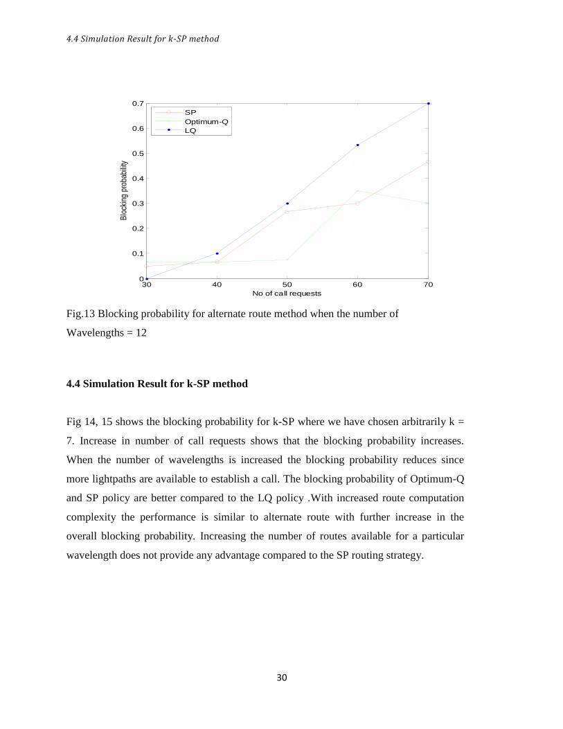
Fig.13 Blocking probability for alternate route method when the number of
Wavelengths = 12 30
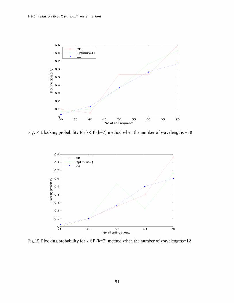
Fig.14 Blocking probability for k-SP (k=7) method when the number of
Wavelengths = 10 31
Fig.15 Blocking probability for k-SP (k=7) when the number of wavelengths = 12 31
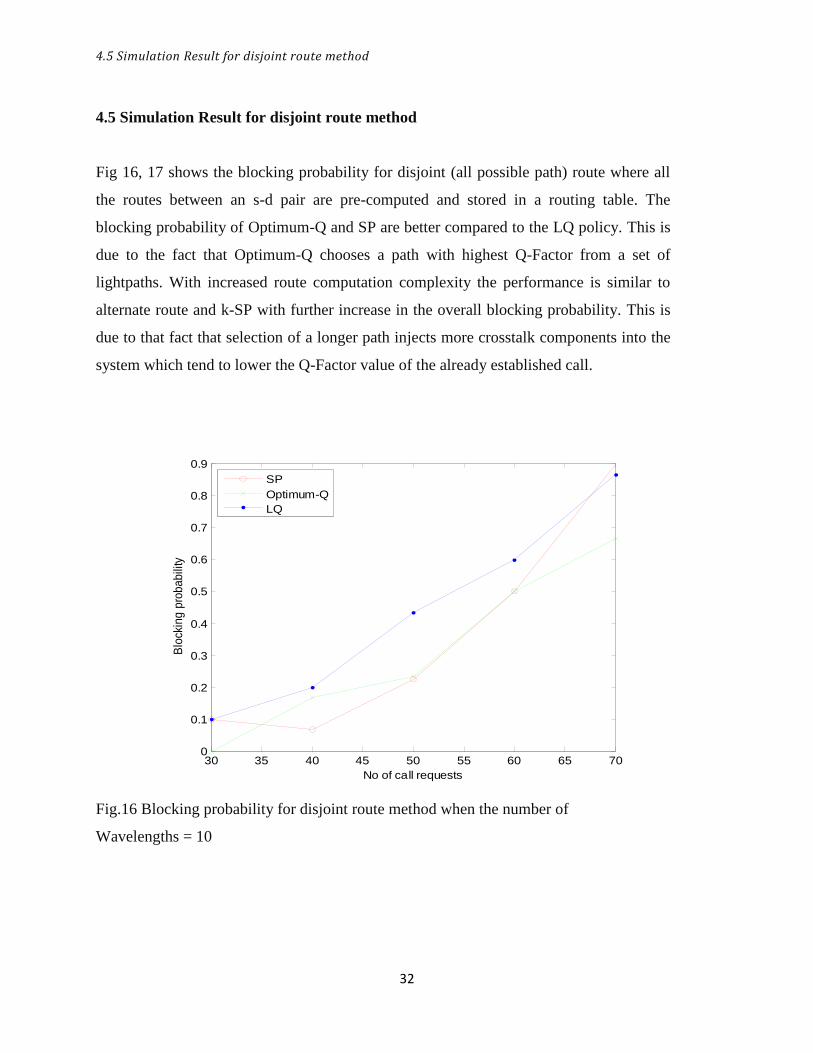
Fig.16 Blocking probability for disjoint route method when the number of
Wavelengths = 10 32
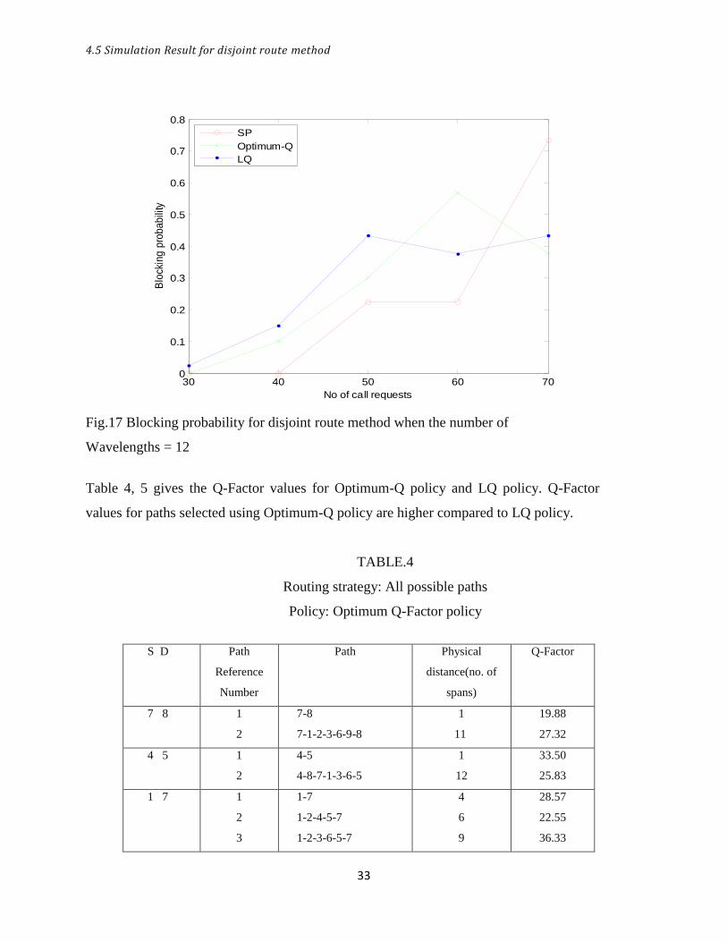
Fig.17 Blocking probability for disjoint route method when the number of
Wavelengths = 12 33

vii
List of Tables
1. Physical parameters for the simulated network 26
2. Optimum Q-Factor policy for SP route computation 28
3. Least Q-Factor policy for SP route computation 28
4. Optimum Q-Factor policy for disjoint route computation 33
5. Least Q-Factor policy for disjoint route computation 34
viii
CONTENTS
Certificate i
Acknowledgement ii
Abstract iii
List of Abbreviation iv
List of Symbols v
List of Figures vi
List of Tables vii
1. INTRODUCTION 2
1.1 Introduction 2
1.2 Proposed Work 3
1.4 Organization of the Thesis 3
2. ALL-OPTICAL NETWORKS 6
2.1 Evolution 6
2.1.1 Control Plane models 7
2.2 WDM/DWDM Technology 9
2.3 PLI aware Routing and Wavelength Assignment 10
2.3.1 Routing strategies 10
2.3.2 Wavelength Assignment methods 12
2.3.3 QoS-aware RWA 13
2.3.4 Linear Impairments 14
2.3.5 Non-Linear Impairments 15
2.4 Crosstalk and ASE noise in all-optical networks 15
2.4.1 Amplifier Spontaneous Emission (ASE) noise 15
2.4.2 Crosstalk in multi-wavelength switched networks 16

ix
3. ADAPTIVE ROUTING AND WAVELENGTH ASSIGNMENT 20
3.1 Network Model 20
3.2 Q-Factor 21
3.3 Proposed Mechanism 21
3.4 Algorithm 22
4. SIMULATION AND RESULTS 25
4.1 Simulated Topology 25
4.2 Simulation Result for Shortest Path method 26
4.3 Simulation Result for Alternate Route method 29
4.4 Simulation Result for k-SP method 30
4.5 Simulation Result for disjoint route method 32
5. CONCLUSION AND FUTURE WORK 36
5.1 Conclusion 36
5.2 Future Work 36
BIBLIOGRAPHY 37

1
CHAPTER 1
INTRODUCTION Introduction
Proposed Work
Organization of the Thesis

1.1 Introduction
2
1.1 Introduction
Optical networks have evolved from opaque (O-E-O conversion at all nodes) and
translucent (few nodes version capabilities) architectures to all-optical or transparent (no
O-E-O conversion) architecture. All-optical networks are a new generation of optical
networks in which the nodes (the wavelength router’s) route signals in the optical
domain. Since signals are not regenerated at the nodes, optical leaks called crosstalk
propagate and accumulate over the lightpath which interferes with the desired signal
causing degradation of the signal quality.
Due to non-ideal filtering characteristics of the nodes, there are two forms of linear
crosstalk that occur in the network i) HEC(hetero-wavelength) or out-of-band crosstalk
which arises from channels on same input route but operating at different wavelengths.
ii)HOC(homo-wavelength) or in-band crosstalk due to crosstalk signals occupying the
same nominal wavelength as the desired signal. Out-band crosstalk does not cause signal
quality deterioration since it can be removed by filtering while in-band crosstalk is
difficult to eliminate completely. Nevertheless, with carefully designed QoS aware RWA
algorithms it is possible to reduce the effect of crosstalk.
When the physical layer is considered ideal, the SLA’s usually employed are based on
bandwidth, and end-to-end delay etc. When the RWA algorithms are PLI-aware they
need to accommodate the SLA’s specific to the optical layer. The SLA parameters
normally used are [1]
a) Optical power: The optical power of a signal that reaches the receiver should fall
within the dynamic range of the receiver to operate reliably below a specific BER.
b) Bit-Error Rate (BER): It is an important measure of the network performance. As the
optical networks evolve achieving higher data rates of 2.5 Gb/s and further, direct
measurement of BER takes a considerable amount of time.
c) Q-Factor: Quality-Factor based approach is considered faster compared to the
traditional BER test. Q-Factor measures the quality of an analog transmission signal in
terms of its signal-to-noise ratio. It takes into account the effect of physical layer
impairments which degrades the signal causing bit errors.
Higher the value of Q-Factor, better the OSNR and hence lower the BER. The
1.2 Proposed Work
3
disadvantage is that when fiber non-linearity is taken into effect the accuracy of the
results is questioned.
The Q-Factor is directly related to the BER by 𝐵𝐸𝑅 = 0.5𝑒𝑟𝑓𝑐 𝑄−𝐹𝑎𝑐𝑡𝑜𝑟
2 using a
Gaussian approximation. We use the Q-Factor based approach to study the effect of
physical layer impairments on the network performance.
1.2 Proposed Work
PLI-aware RWA algorithms have been proposed in the literature in [2, 3, 4] and in
[5].We try to capture the most significant impairments in-band crosstalk and ASE noise,
when we estimate the Q-Factor. With carefully designed QoS aware RWA algorithms it
is possible to reduce the effect of crosstalk.
Because both crosstalk and wavelength availability depend on the network state, it is
important that such RWA algorithms consider only those routes that can meet the
wavelength continuity constraint and that dynamically accounts for QoS at route
establishment time. Such RWA algorithms are said to be adaptive, and we propose three
adaptive RWA algorithms (shortest path, Optimum Q-Factor and Least Q-Factor) that
account for the network state both in terms of the existing connections and current QoS at
both the routing and wavelength assignment steps to evaluate the network blocking
performance.
In our work while evaluating the blocking performance of the proposed adaptive RWA
algorithms, different route selection methods have been employed. The blocking
performance and computational complexity of the methods like SP, alternate route, k-SP
and disjoint route (all possible paths) are evaluated and compared.
1.3 Organization of the thesis
Chapter 2 deals with the evolution of all-optical networks and the associated
WDM/DWDM technology, in which optical components are discussed.RWA problem is
considered; specific physical layer impairments like Crosstalk and ASE are studied.

1.3 Organization of the thesis
4
Chapter 3 discuss’ adaptive routing and wavelength assignment; a network model is
presented to describe the process of crosstalk generation and Q-Factor model is described
which is used to evaluate the network performance. Lastly adaptive RWA algorithm is
explained.
Chapter 4 deals with simulation of a 9-node network topology and the results for various
methods that are employed during the RWA process like SP, alternate route, k-SP and
disjoint route (all possible paths)
Chapter 5 concludes our work with a brief analysis of the results obtained.

5
CHAPTER 2
ALL-OPTICAL NETWORKS
Evolution
WDM/DWDM Technology
PLI aware Routing and Wavelength Assignment
Crosstalk and ASE noise in all-optical networks
2.1 Evolution
6
ALL-OPTICAL NETWORKS
2.1 Evolution
Signal transmission over optical fiber provides advantages like low loss, high bandwidth,
low levels of undesirable transmission impairments, immunity to electromagnetic
interference and long life-spans. The three low loss windows used for optical
communication are in the 0.8, 1.3 and 1.55 µm infrared wavelength bands [6]. The 1.55
µm band has the lowest loss of 0.25dB/km with 1.3 µm band having a loss of 0.5dB/km.
Early fibers were multimode fibers with core diameters of 50 to 85mm.The diameter is
large compared to the operating wavelength and hence supported multiple propagation
modes. Multi mode fiber transmission suffers from intermodal dispersion.
With the advent of single mode fiber transmission, the intermodal dispersion was
completely eliminated. The core diameter is about 8 to 10µm, which is a small multiple
of the operating wavelength. There was a dramatic increase in the bit rate and distance
between regenerators.
Later Erbium Doped Fiber Amplifiers (EDFA) enabled simultaneous amplification at
many wavelengths. This allowed the use of multiple wavelengths with each operating at a
specific bit-rate. Wavelength division multiplexing (WDM) systems increased the system
capacity to a great extent.
Optical layer will move from providing simple transmission pipes to a managed optical
network. Higher layer equipments like SONET or IP boxes handle switching and routing
of data in the electrical domain after optical-electrical conversion when the optical layer
is used only as a transmission medium.
In case of managed optical network, the optical layer handles the functions like switching
and routing without the need for an Optical-Electrical-Optical conversion resulting in an
all-optical network. All-optical networks are transparent networks referring to the ability
of the network to carry data regardless of the protocol or framing structure used.
2.1 Evolution
7
2.1.1 Control plane models
The optical layer provides circuit switched, high bandwidth connections to its client layer
which is usually the SONET box or IP router. Different models have been proposed to
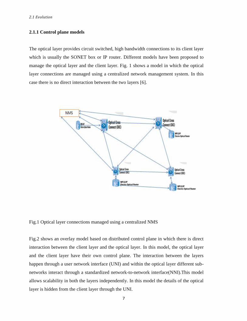
manage the optical layer and the client layer. Fig. 1 shows a model in which the optical
layer connections are managed using a centralized network management system. In this
case there is no direct interaction between the two layers [6].
Fig.1 Optical layer connections managed using a centralized NMS
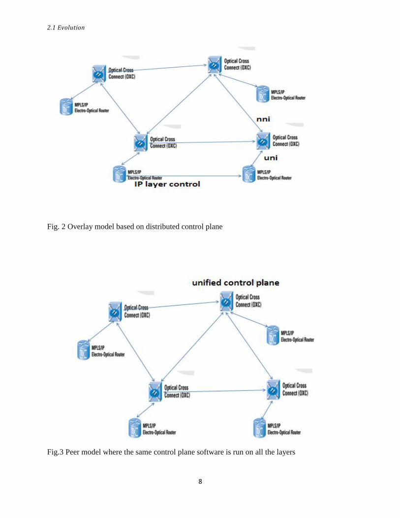
Fig.2 shows an overlay model based on distributed control plane in which there is direct
interaction between the client layer and the optical layer. In this model, the optical layer
and the client layer have their own control plane. The interaction between the layers
happen through a user network interface (UNI) and within the optical layer different sub-
networks interact through a standardized network-to-network interface(NNI).This model
allows scalability in both the layers independently. In this model the details of the optical
layer is hidden from the client layer through the UNI.
2.1 Evolution
8
Fig. 2 Overlay model based on distributed control plane
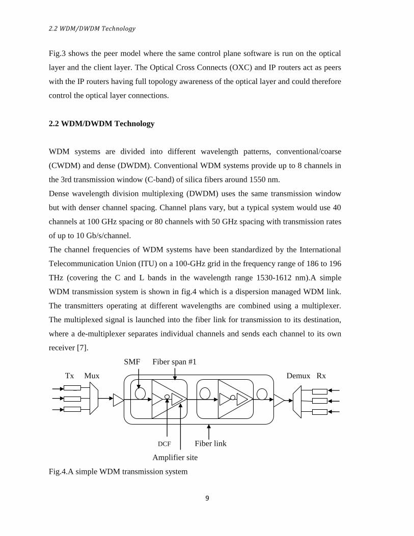
Fig.3 Peer model where the same control plane software is run on all the layers
2.2 WDM/DWDM Technology
9
Fig.3 shows the peer model where the same control plane software is run on the optical
layer and the client layer. The Optical Cross Connects (OXC) and IP routers act as peers
with the IP routers having full topology awareness of the optical layer and could therefore
control the optical layer connections.
2.2 WDM/DWDM Technology
WDM systems are divided into different wavelength patterns, conventional/coarse
(CWDM) and dense (DWDM). Conventional WDM systems provide up to 8 channels in
the 3rd transmission window (C-band) of silica fibers around 1550 nm.
Dense wavelength division multiplexing (DWDM) uses the same transmission window
but with denser channel spacing. Channel plans vary, but a typical system would use 40
channels at 100 GHz spacing or 80 channels with 50 GHz spacing with transmission rates
of up to 10 Gb/s/channel.
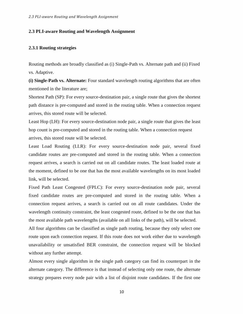
The channel frequencies of WDM systems have been standardized by the International
Telecommunication Union (ITU) on a 100-GHz grid in the frequency range of 186 to 196
THz (covering the C and L bands in the wavelength range 1530-1612 nm).A simple
WDM transmission system is shown in fig.4 which is a dispersion managed WDM link.
The transmitters operating at different wavelengths are combined using a multiplexer.
The multiplexed signal is launched into the fiber link for transmission to its destination,
where a de-multiplexer separates individual channels and sends each channel to its own
receiver [7].
SMF Fiber span #1
Tx Mux Demux Rx
E EDFA
DCF Fiber link
Amplifier site
Fig.4.A simple WDM transmission system
2.3 PLI-aware Routing and Wavelength Assignment
10
2.3 PLI-aware Routing and Wavelength Assignment
2.3.1 Routing strategies
Routing methods are broadly classified as (i) Single-Path vs. Alternate path and (ii) Fixed
vs. Adaptive.
(i) Single-Path vs. Alternate: Four standard wavelength routing algorithms that are often
mentioned in the literature are;
Shortest Path (SP): For every source-destination pair, a single route that gives the shortest
path distance is pre-computed and stored in the routing table. When a connection request
arrives, this stored route will be selected.
Least Hop (LH): For every source-destination node pair, a single route that gives the least
hop count is pre-computed and stored in the routing table. When a connection request
arrives, this stored route will be selected.
Least Load Routing (LLR): For every source-destination node pair, several fixed
candidate routes are pre-computed and stored in the routing table. When a connection
request arrives, a search is carried out on all candidate routes. The least loaded route at
the moment, defined to be one that has the most available wavelengths on its most loaded
link, will be selected.
Fixed Path Least Congested (FPLC): For every source-destination node pair, several
fixed candidate routes are pre-computed and stored in the routing table. When a
connection request arrives, a search is carried out on all route candidates. Under the
wavelength continuity constraint, the least congested route, defined to be the one that has
the most available path wavelengths (available on all links of the path), will be selected.
All four algorithms can be classified as single path routing, because they only select one
route upon each connection request. If this route does not work either due to wavelength
unavailability or unsatisfied BER constraint, the connection request will be blocked
without any further attempt.
Almost every single algorithm in the single path category can find its counterpart in the
alternate category. The difference is that instead of selecting only one route, the alternate
strategy prepares every node pair with a list of disjoint route candidates. If the first one
2.3. PLI-aware Routing and Wavelength Assignment
11
does not work, the second one is examined, then the third and so on, until one route is
found to be good for assignment.
Therefore we can apply the above four single path routing algorithms to the alternate
domain as follows:
Alternate Shortest Path (Alt-SP): For every source-destination pair, an ordered list of
routes that gives the shortest path distance, the second disjoint shortest path distance, the
third disjoint, etc are pre-computed and stored in the routing table. When a connection
request arrives, this stored list will be searched in order, until a route that satisfies all the
requirements is found.
Alternate Least Hop (Alt-LH): For every source-destination node pair, an ordered list of
routes that gives the least hop count, the second disjoint least hop count, the third disjoint,
etc are pre-computed and stored in the routing table. When a connection request arrives,
this stored list will be searched in order, until a route that satisfies all the requirements is
found.
Alternate Least Load Routing (Alt-LLR): For every source-destination node pair, several
fixed candidate routes are pre-computed and stored in the routing table. When a
connection request arrives, every candidate is computed for its current load condition,
and an ordered list is dynamically established with the least loaded route first and the
most loaded route last. Then this list will be searched in order, until a route that satisfies
all the requirements is found.
Alternate Fixed Path Least Congested (Alt-FPLC): For every source-destination node
pair, several fixed candidate routes are pre-computed and stored in the routing table.
When a connection request arrives, every candidate is computed for its current load
conditions under the wavelength continuity constraint, and an ordered list is dynamically
established with the least congested route first and the most congested route last. Then
this list will be searched in order, until a route that satisfies all the requirements is found.
Clearly alternate routing increases the computation complexity for route search compared
to single path routing. However, the tradeoff is usually a significantly improved blocking
performance due to added redundancy.
2.3 PLI-aware Routing and Wavelength Assignment
12
(ii) Fixed vs. Adaptive:
Depending on how routes are found routing could be fixed or adaptive. The fixed strategy
pre-defines everything in the routing tables off-line. A fixed set of routes in a fixed
searching order are stored in the routing table for every source-destination node pair.
Therefore, when a call arrives, the only routing action that the source node takes is to
check whether the wavelength and the BER constraints are satisfied by the primary route,
and if not, proceed to examine the next if there is one, and so on. Fixed routing is easy to
implement with least amount of control overhead, but the blocking performance is
usually degraded because of lack of traffic engineering. Typical examples of fixed
routing are SP, Alt-SP, LH and Alt-LH.
The adaptive strategy, in contrast, establishes the routing table on a call-to-call basis
according to the current link-state information. For algorithms like LLR, Alt-LLR, FPLC
and Alt-FPLC, although their route candidates are pre-defined, the searching order is
calculated adaptively based on the load condition. Hence they can be categorized under
adaptive routing.
2.3.2 Wavelength Assignment Methods
The wavelength assignment subroutine operates on a set of candidate wavelengths that
are given on a previously selected routing path (or paths). The set may be ordered,
according to a given policy, or unordered, i.e., the wavelengths are treated in a round-
robin way. Given a set of candidate paths, the wavelength selection phase can be
performed either sequentially or in parallel. This is similar to the routing sub-routine. In
the sequential approach, the first non-occupied wavelength that satisfies given network-
layer and physical-layer constraints is selected. Such an approach is called First-Fit (FF)
selection method. On the contrary, some PLI-RWA algorithms try to look through all of
the candidate wavelengths so as to find the Best-Fit (BF), i.e., the most appropriate one.
Finally, a random selection, which means choosing randomly amongst the available
wavelengths, can be performed. It is well known that wavelength blocking probability of
a random Wavelength Assignment algorithm is worse than that of the First-Fit algorithm.
2.3 PLI-aware Routing and Wavelength Assignment
13
2.3.3 QoS aware RWA
When selecting a lightpath (route and wavelength) a PLI aware RWA algorithm for a
transparent network has to take into account the physical layer impairments and
wavelength availability.
With static traffic, the entire set of connection requests is known in advance and the static
(offline) RWA problem of setting up these connection requests is named the permanent
lightpath establishment (PLD) problem.
In a dynamic traffic scenario the connections are requested in some random fashion and
the lightpaths have to be set up as needed. There are several heuristic algorithms
proposed in the literature dealing with the wavelength assignment sub problem such as
Random, First-Fit, and Least-used etc.
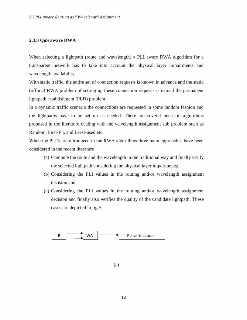
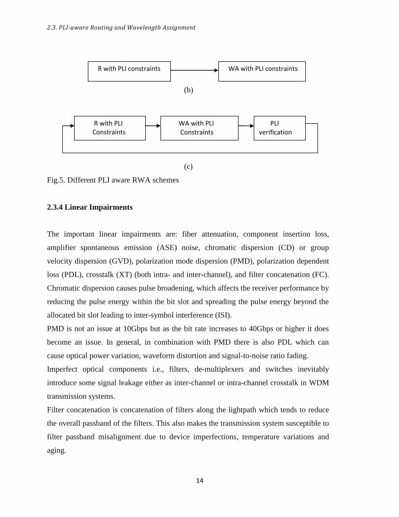
When the PLI’s are introduced in the RWA algorithms three main approaches have been
considered in the recent literature
(a) Compute the route and the wavelength in the traditional way and finally verify
the selected lightpath considering the physical layer impairments;
(b) Considering the PLI values in the routing and/or wavelength assignment
decision and
(c) Considering the PLI values in the routing and/or wavelength assignment
decision and finally also verifies the quality of the candidate lightpath. These
cases are depicted in fig.5
(a)
R WA PLI verification
2.3. PLI-aware Routing and Wavelength Assignment
14
(b)
(c)
Fig.5. Different PLI aware RWA schemes
2.3.4 Linear Impairments
The important linear impairments are: fiber attenuation, component insertion loss,
amplifier spontaneous emission (ASE) noise, chromatic dispersion (CD) or group
velocity dispersion (GVD), polarization mode dispersion (PMD), polarization dependent
loss (PDL), crosstalk (XT) (both intra- and inter-channel), and filter concatenation (FC).
Chromatic dispersion causes pulse broadening, which affects the receiver performance by
reducing the pulse energy within the bit slot and spreading the pulse energy beyond the
allocated bit slot leading to inter-symbol interference (ISI).
PMD is not an issue at 10Gbps but as the bit rate increases to 40Gbps or higher it does
become an issue. In general, in combination with PMD there is also PDL which can
cause optical power variation, waveform distortion and signal-to-noise ratio fading.
Imperfect optical components i.e., filters, de-multiplexers and switches inevitably
introduce some signal leakage either as inter-channel or intra-channel crosstalk in WDM
transmission systems.
Filter concatenation is concatenation of filters along the lightpath which tends to reduce
the overall passband of the filters. This also makes the transmission system susceptible to
filter passband misalignment due to device imperfections, temperature variations and
aging.
R with PLI Constraints
WA with PLI Constraints
PLI verification
R with PLI constraints WA with PLI constraints
2.4 Crosstalk and ASE noise in all-optical networks
15
2.3.5 Non-Linear Impairments
The most important non-linear impairments are self phase modulation (SPM), cross phase
modulation (XPM), four wave mixing (FWM), stimulated brillouin scattering (SBS) and
stimulated Raman scattering (SRS).
The nonlinear phase shift manifests as phase modulation. In SPM the phase of the signal
is modulated by its own intensity; while in XPM the signal phase is modulated by the
intensity of other signals. The primary effect of these impairments is pulse broadening in
frequency domain without changing the shape of the signal.SBS and SRS involve non
elastic scattering mechanism. These impairments set an upper limit on the amount of
optical power that can be launched into an optical link.
2.4 Crosstalk and ASE noise in all-optical networks
2.4.1 Amplifier Spontaneous Emission (ASE) noise
In optically amplified systems, erbium doped fiber amplifiers (EDFA) are used to provide
sufficient gain to compensate for the power loss and extend the range of signal
transmission. This amplifier acts as a source of additive ASE noise which affects the
signal quality. This noise is often quantified with noise figure (NF).The NF is a factor
which says how much higher the noise power spectral density of the amplified output is
compared with the input noise power spectral density times the amplification factor and
is often specified in decibels (dB) [9]. ASE noise is emitted by the amplifier in both
directions, but only the forward ASE is a direct concern to system performance since that
noise will co-propagate with the signal to the receiver where it degrades system
performance. Counter-propagating ASE can, however, lead to degradation of the
amplifier’s performance since the ASE can deplete the inversion level and thereby reduce
the gain of the amplifier. Excess ASE is an unwanted effect in lasers, since it dissipates
some of the laser’s power. In optical amplifiers, ASE limits the achievable gain of the
amplifier and increases its noise level. The ASE noise mixes with the optical signal and
produces beat noise components at the square-law receiver. The ASE noise is very

2.4 Crosstalk and ASE noise in all-optical networks
16
broadband (∼40 nm) and needs to be carefully analyzed to evaluate its degrading effect
on system performance.
2.4.2 Crosstalk in multi-wavelength switched networks
There are two potential sources for generating optical crosstalk in an OXC. One is the
crosstalk from the optical space switches and the other is due to non-ideal wavelength
filtering [8]. Filter associated crosstalk from the two immediately adjacent wavelength
channels considering four signal wavelengths (𝜆1,𝜆2, 𝜆3, 𝜆4) with 𝜆2 as the desired
signal.After the non-ideal filtering,𝜆2 carrier suffers crosstalk from 𝜆1 𝑎𝑛𝑑 𝜆3 which
enter the multiwavelength transport network node on the same input fiber.In a similar
manner crosstalk coupling occurs in other channels. Fig 6 shows the effect of crosstalk.
𝜆1
𝜆2
𝜆1 𝜆2 𝜆3
𝜆3
𝜆4
Fig.6 Crosstalk due to the non-ideal filtering
WDM channel multiplexing after wavelength selection and switching
The effect of crosstalk on λ2 with two adjacent channels λ1 and λ3
2.4 Crosstalk and ASE noise in all optical networks
17
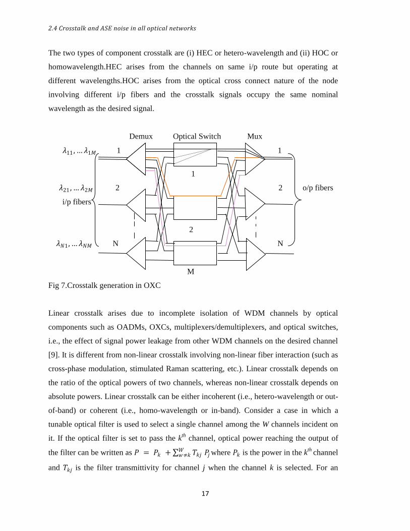
The two types of component crosstalk are (i) HEC or hetero-wavelength and (ii) HOC or
homowavelength.HEC arises from the channels on same i/p route but operating at
different wavelengths.HOC arises from the optical cross connect nature of the node
involving different i/p fibers and the crosstalk signals occupy the same nominal
wavelength as the desired signal.
Demux Optical Switch Mux
𝜆11 ,…𝜆1𝑀 1 1
1
𝜆21 ,…𝜆2𝑀 2 2 o/p fibers
i/p fibers
2
𝜆𝑁1,…𝜆𝑁𝑀 N N
M
M
Fig 7.Crosstalk generation in OXC
Linear crosstalk arises due to incomplete isolation of WDM channels by optical
components such as OADMs, OXCs, multiplexers/demultiplexers, and optical switches,
i.e., the effect of signal power leakage from other WDM channels on the desired channel
[9]. It is different from non-linear crosstalk involving non-linear fiber interaction (such as
cross-phase modulation, stimulated Raman scattering, etc.). Linear crosstalk depends on
the ratio of the optical powers of two channels, whereas non-linear crosstalk depends on
absolute powers. Linear crosstalk can be either incoherent (i.e., hetero-wavelength or out-
of-band) or coherent (i.e., homo-wavelength or in-band). Consider a case in which a
tunable optical filter is used to select a single channel among the W channels incident on
it. If the optical filter is set to pass the kth
channel, optical power reaching the output of
the filter can be written as 𝑃 = 𝑃𝑘 + 𝑇𝑘𝑗𝑊𝑤≠𝑘 𝑃𝑗 where 𝑃𝑘 is the power in the k
th channel
and 𝑇𝑘𝑗 is the filter transmittivity for channel j when the channel k is selected. For an

2.4 Crosstalk and ASE noise in all optical networks
18
ideal filter 𝑇𝑘𝑗 should be zero. Crosstalk occurs if 𝑇𝑘𝑗 ≠ 0 for j ≠k. This is out-of-band
crosstalk because it belongs to the channels lying outside the spectral band occupied by
the channel selected. It is incoherent because it depends only on the power of the
neighboring channels. The in-band crosstalk can be easily understood by considering a
typical structure of an OXC without in-built amplifiers as shown in Fig 7. The OXC
consists of N fiber ports and M optical switches. Wavelength 1 in input fiber 1, denoted
by 𝜆11 , is affected by the N − 1 crosstalk components due to the leakage from the N − 1
signals with wavelength 1 on the other N − 1 input fibers, 𝜆21 , 𝜆31 . . . ,𝜆𝑁1, when passing
through the optical switch 1 (shown in dotted lines). Similarly, when wavelength 1 is
demultiplexed to one path, there will be a fraction of it in each of the other M − 1 outputs
of the corresponding demultiplexers. Passed through the optical switches, the main signal
is multiplexed with M − 1 signals with different wavelengths. At the same time, the M −
1 crosstalk contributions of wavelength 1in these M − 1 paths are combined with the
main signal (shown in orange and blue lines). Assume ε is the isolation of
multiplexers/demultiplexers, P is power of the input signal, and then the crosstalk
contributions are 𝜀2(M − 1) P. The computation of crosstalk becomes quite complicated
as the number of crosstalk elements which the signal passes through increases, and
should be considered in the design of WDM networks. Crosstalk effects can be mitigated
by the use of intelligent wavelength assignment techniques.

19
CHAPTER 3
ADAPTIVE ROUTING AND WAVELENGTH ASSIGNMENT
Network Model
Q-Factor
Proposed Mechanism
Algorithm
3.1 Network Model
20
ADAPTIVE ROUTING AND WAVELENGTH
ASSIGNMENT
3.1. Network Model
𝑃1 𝜆𝑖
𝑃0
router1 router2
𝜆𝑖 𝑃2
Insufficient crosstalk rejection
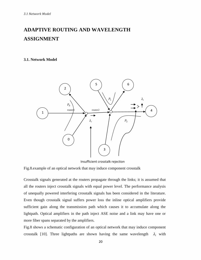
Fig.8.example of an optical network that may induce component crosstalk
Crosstalk signals generated at the routers propagate through the links; it is assumed that
all the routers inject crosstalk signals with equal power level. The performance analysis
of unequally powered interfering crosstalk signals has been considered in the literature.
Even though crosstalk signal suffers power loss the inline optical amplifiers provide
sufficient gain along the transmission path which causes it to accumulate along the
lightpath. Optical amplifiers in the path inject ASE noise and a link may have one or
more fiber spans separated by the amplifiers.
Fig.8 shows a schematic configuration of an optical network that may induce component
crosstalk [10]. Three lightpaths are shown having the same wavelength 𝜆𝑖 with
1 4
0
3
2 5 6
3.2 Q-Factor
21
𝑃0,𝑃1 𝑎𝑛𝑑 𝑃2 established between the nodes (0, 2), (5, 6) and (3, 4) respectively. Due to
non-ideal characteristics the crosstalk signal generated at the router1 appears as a
component crosstalk at the wavelength router2.
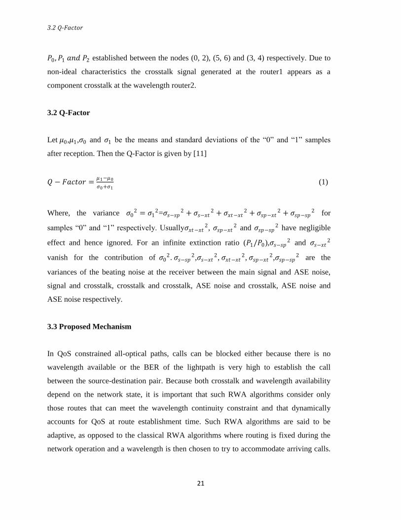
3.2 Q-Factor
Let 𝜇0,𝜇1,𝜎0 and 𝜎1 be the means and standard deviations of the “0” and “1” samples
after reception. Then the Q-Factor is given by [11]
𝑄 − 𝐹𝑎𝑐𝑡𝑜𝑟 =𝜇1−𝜇0
𝜎0+𝜎1 (1)
Where, the variance 𝜎02 = 𝜎1
2=𝜎𝑠−𝑠𝑝2 + 𝜎𝑠−𝑥𝑡
2 + 𝜎𝑥𝑡−𝑥𝑡2 + 𝜎𝑠𝑝−𝑥𝑡
2 + 𝜎𝑠𝑝−𝑠𝑝2 for
samples “0” and “1” respectively. Usually𝜎𝑥𝑡−𝑥𝑡2, 𝜎𝑠𝑝−𝑥𝑡
2 and 𝜎𝑠𝑝−𝑠𝑝2 have negligible
effect and hence ignored. For an infinite extinction ratio (𝑃1/𝑃0),𝜎𝑠−𝑠𝑝2 and 𝜎𝑠−𝑥𝑡
2
vanish for the contribution of 𝜎02. 𝜎𝑠−𝑠𝑝
2,𝜎𝑠−𝑥𝑡2, 𝜎𝑥𝑡−𝑥𝑡
2, 𝜎𝑠𝑝−𝑥𝑡2,𝜎𝑠𝑝−𝑠𝑝
2 are the
variances of the beating noise at the receiver between the main signal and ASE noise,
signal and crosstalk, crosstalk and crosstalk, ASE noise and crosstalk, ASE noise and
ASE noise respectively.
3.3 Proposed Mechanism
In QoS constrained all-optical paths, calls can be blocked either because there is no
wavelength available or the BER of the lightpath is very high to establish the call
between the source-destination pair. Because both crosstalk and wavelength availability
depend on the network state, it is important that such RWA algorithms consider only
those routes that can meet the wavelength continuity constraint and that dynamically
accounts for QoS at route establishment time. Such RWA algorithms are said to be
adaptive, as opposed to the classical RWA algorithms where routing is fixed during the
network operation and a wavelength is then chosen to try to accommodate arriving calls.
3.4 Algorithm
22
In our approach the Q-Factor of a candidate lightpath is computed during the admission
phase of a call. Once a call has been setup in the network, its Q-Factor could vary slightly
depending on the instantaneous traffic in the network, typically the Q-Factor of the
existing call in the network may decrease slightly when a new call is established and it
may increase slightly when another ongoing call leaves the network. The adaptive RWA
algorithm employed in this work ensures that a call is set-up on a good route and
wavelength when it is admitted into the network.
Adaptive routing and wavelength assignment is a technique where the choice of a route
depends on the network state [11]. This means that a wavelength is chosen according to a
policy (in this case First-Fit selection method, where the wavelength is pre-ordered) and a
shortest route is computed in an altered topology which contains only the links from the
original topology where the considered wavelength can be used. Q-Factor of an existing
call gets affected when a new call arrives with the same wavelength; hence the Q-Factor
is estimated to ensure that it is above a threshold (usually 6 which gives a min BER
of10−9) for all calls including the current call.
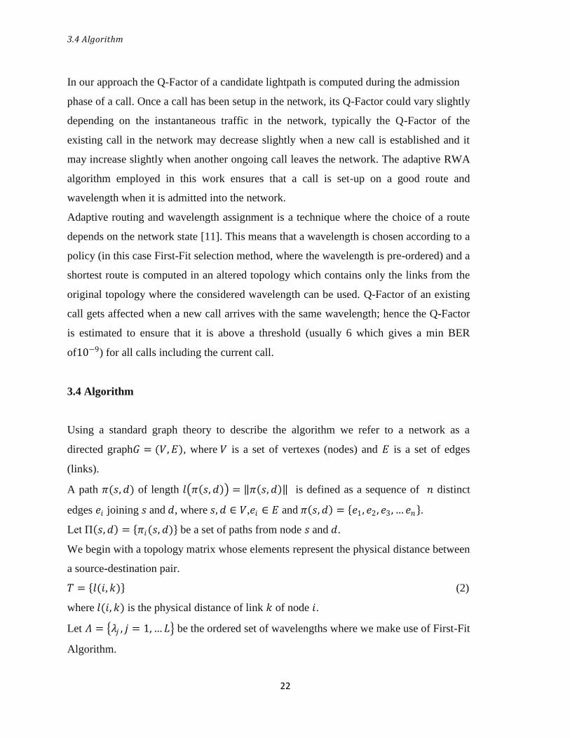
3.4 Algorithm
Using a standard graph theory to describe the algorithm we refer to a network as a
directed graph𝐺 = (𝑉,𝐸), where 𝑉 is a set of vertexes (nodes) and 𝐸 is a set of edges
(links).
A path 𝜋(𝑠,𝑑) of length 𝑙 𝜋 𝑠, 𝑑 = 𝜋 𝑠,𝑑 is defined as a sequence of 𝑛 distinct
edges 𝑒𝑖 joining 𝑠 and 𝑑, where 𝑠, 𝑑 ∈ 𝑉,𝑒𝑖 ∈ 𝐸 and 𝜋 𝑠,𝑑 = 𝑒1, 𝑒2, 𝑒3,…𝑒𝑛 .
Let П 𝑠,𝑑 = 𝜋𝑖(𝑠, 𝑑) be a set of paths from node 𝑠 and 𝑑.
We begin with a topology matrix whose elements represent the physical distance between
a source-destination pair.
𝑇 = 𝑙(𝑖,𝑘) (2)
where 𝑙(𝑖, 𝑘) is the physical distance of link 𝑘 of node 𝑖.
Let 𝛬 = 𝜆𝑗 , 𝑗 = 1,…𝐿 be the ordered set of wavelengths where we make use of First-Fit
Algorithm.
3.4 Algorithm
23
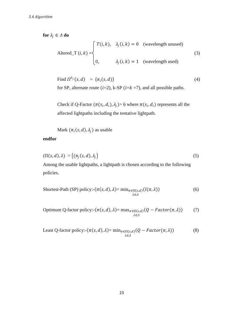
for 𝜆𝑗 ∈ 𝛬 do
𝑇(𝑖,𝑘), 𝜆𝑗 𝑖,𝑘 = 0 (wavelength unused)
Altered_T (𝑖,𝑘) = (3)
0, 𝜆𝑗 𝑖,𝑘 = 1 (wavelength used)
Find П𝜆𝑗 𝑠, 𝑑 = 𝜋𝑖(𝑠,𝑑) (4)
for SP, alternate route (𝑖=2), k-SP (𝑖=𝑘 =7), and all possible paths.
Check if Q-Factor (𝜋(𝑠𝑖 ,𝑑𝑖),𝜆𝑗 )> 6 where 𝜋(𝑠𝑖 ,𝑑𝑖) represents all the
affected lightpaths including the tentative lightpath.
Mark (𝜋𝑖 𝑠,𝑑 , 𝜆𝑗 ) as usable
endfor
(П 𝑠,𝑑 , 𝜆) = (𝜋𝑗 𝑠,𝑑 , 𝜆𝑗 (5)
Among the usable lightpaths, a lightpath is chosen according to the following
policies.
Shortest-Path (SP) policy:- 𝜋 𝑠, 𝑑 ,𝜆 = min𝜋∈П 𝑠,𝑑
𝜆∈𝛬
𝑙(𝜋, 𝜆) (6)
Optimum Q-factor policy:- 𝜋 𝑠,𝑑 , 𝜆 = max𝜋∈П 𝑠,𝑑
𝜆∈𝛬
𝑄 − 𝐹𝑎𝑐𝑡𝑜𝑟(𝜋, 𝜆) (7)
Least Q-factor policy:- 𝜋 𝑠,𝑑 , 𝜆 = min𝜋∈П 𝑠,𝑑
𝜆∈𝛬
𝑄 − 𝐹𝑎𝑐𝑡𝑜𝑟(𝜋, 𝜆) (8)

24
CHAPTER 4
SIMULATION AND RESULTS
Simulated Topology
Simulation Result for Shortest Path method
Simulation Result for Alternate Route method
Simulation Result for k-SP method
Simulation Result for disjoint route method

4.1 Simulated Topology
25
SIMULATION AND RESULTS
4.1 Simulated Topology
We consider a 9-node network topology for simulation with the numbers on the links
specifying the number of spans between two nodes. Here the span length is taken as
70km. Table.1 shows the physical parameters used for simulation purpose [11].
Fig.9.Topology considered for simulation with the number specifying the number of
spans with a span length of 70km.
4.2 Simulation result for shortest path method
26
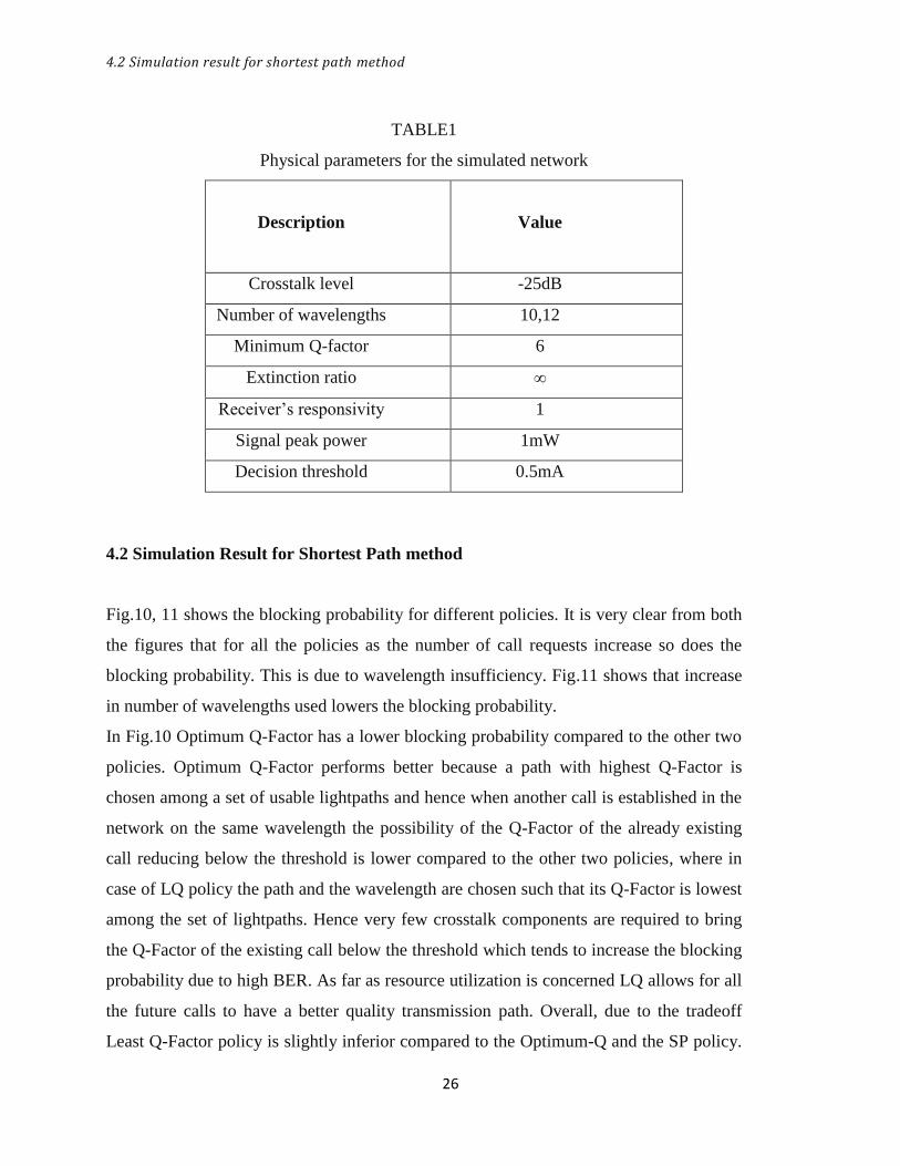
TABLE1
Physical parameters for the simulated network
Description
Value
Crosstalk level -25dB
Number of wavelengths 10,12
Minimum Q-factor 6
Extinction ratio ∞
Receiver’s responsivity 1
Signal peak power 1mW
Decision threshold 0.5mA
4.2 Simulation Result for Shortest Path method
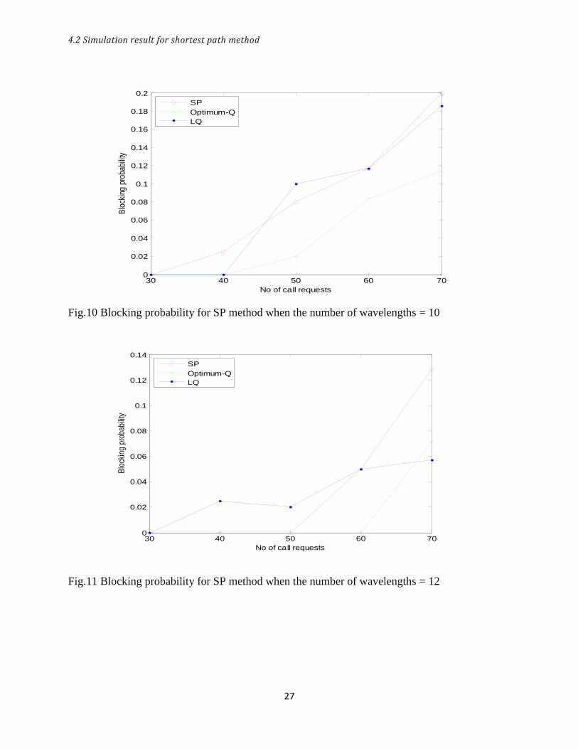
Fig.10, 11 shows the blocking probability for different policies. It is very clear from both
the figures that for all the policies as the number of call requests increase so does the
blocking probability. This is due to wavelength insufficiency. Fig.11 shows that increase
in number of wavelengths used lowers the blocking probability.
In Fig.10 Optimum Q-Factor has a lower blocking probability compared to the other two
policies. Optimum Q-Factor performs better because a path with highest Q-Factor is
chosen among a set of usable lightpaths and hence when another call is established in the
network on the same wavelength the possibility of the Q-Factor of the already existing
call reducing below the threshold is lower compared to the other two policies, where in
case of LQ policy the path and the wavelength are chosen such that its Q-Factor is lowest
among the set of lightpaths. Hence very few crosstalk components are required to bring
the Q-Factor of the existing call below the threshold which tends to increase the blocking
probability due to high BER. As far as resource utilization is concerned LQ allows for all
the future calls to have a better quality transmission path. Overall, due to the tradeoff
Least Q-Factor policy is slightly inferior compared to the Optimum-Q and the SP policy.
4.2 Simulation result for shortest path method
27
Fig.10 Blocking probability for SP method when the number of wavelengths = 10
Fig.11 Blocking probability for SP method when the number of wavelengths = 12
30 40 50 60 700
0.02
0.04
0.06
0.08
0.1
0.12
0.14
0.16
0.18
0.2
No of call requests
Blo
ckin
g p
roba
bilit
y
SP
Optimum-Q
LQ
30 40 50 60 700
0.02
0.04
0.06
0.08
0.1
0.12
0.14
No of call requests
Blo
ckin
g p
roba
bilit
y
SP
Optimum-Q
LQ

4.2 Simulation Result for Shortest Path method
28
Table 2, 3 gives the Q-Factor values for Optimum-Q policy and LQ policy show for
certain paths. Comparison shows a relatively higher value for Optimum-Q policy
compared to the LQ policy.
TABLE.2
Routing strategy: Shortest Path
Policy: Optimum Q-Factor policy
S D Path
Reference
Number
Path Physical
distance(no. of
spans)
Q-Factor
1 5 1
2
1-3-6-5
1-7-5
3
6
11.83
14.64
7 6 1
2
7-5-6
7-8-9-6
3
5
8.65
25.47
5 2 1
2
5-4-2
5-6-3-2
3
6
9.91
12.05
TABLE.3
Routing strategy: Shortest Path
Policy: Least Q-Factor policy
S D Path
Reference
Number
Path Physical
distance(no. of
spans)
Q-Factor
6 8 1
2
6-9-8
6-5-4-8
4
6
8.71
9.20
9 7 1
2
9-8-7
9-6-3-1-7
3
8
14.13
6.63
5 1 1
2
5-6-3-1
5-7-1
3
6
9.31
6.84
4.3 Simulation Result for Alternate Route method
29
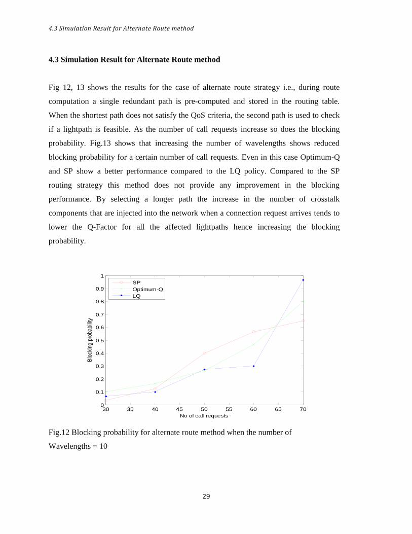
4.3 Simulation Result for Alternate Route method
Fig 12, 13 shows the results for the case of alternate route strategy i.e., during route
computation a single redundant path is pre-computed and stored in the routing table.
When the shortest path does not satisfy the QoS criteria, the second path is used to check
if a lightpath is feasible. As the number of call requests increase so does the blocking
probability. Fig.13 shows that increasing the number of wavelengths shows reduced
blocking probability for a certain number of call requests. Even in this case Optimum-Q
and SP show a better performance compared to the LQ policy. Compared to the SP
routing strategy this method does not provide any improvement in the blocking
performance. By selecting a longer path the increase in the number of crosstalk
components that are injected into the network when a connection request arrives tends to
lower the Q-Factor for all the affected lightpaths hence increasing the blocking
probability.
Fig.12 Blocking probability for alternate route method when the number of
Wavelengths = 10
30 35 40 45 50 55 60 65 700
0.1
0.2
0.3
0.4
0.5
0.6
0.7
0.8
0.9
1
No of call requests
Blo
ckin
g p
roba
bilit
y
SP
Optimum-Q
LQ
4.4 Simulation Result for k-SP method
30
Fig.13 Blocking probability for alternate route method when the number of
Wavelengths = 12
4.4 Simulation Result for k-SP method
Fig 14, 15 shows the blocking probability for k-SP where we have chosen arbitrarily k =
7. Increase in number of call requests shows that the blocking probability increases.
When the number of wavelengths is increased the blocking probability reduces since
more lightpaths are available to establish a call. The blocking probability of Optimum-Q
and SP policy are better compared to the LQ policy .With increased route computation
complexity the performance is similar to alternate route with further increase in the
overall blocking probability. Increasing the number of routes available for a particular
wavelength does not provide any advantage compared to the SP routing strategy.
30 40 50 60 700
0.1
0.2
0.3
0.4
0.5
0.6
0.7
No of call requests
Blo
ckin
g p
roba
bilit
y
SP
Optimum-Q
LQ
4.4 Simulation Result for k-SP route method
31
Fig.14 Blocking probability for k-SP (k=7) method when the number of wavelengths =10
Fig.15 Blocking probability for k-SP (k=7) method when the number of wavelengths=12
30 35 40 45 50 55 60 65 700
0.1
0.2
0.3
0.4
0.5
0.6
0.7
0.8
0.9
No of call requests
Blo
ckin
g p
roba
bilit
y
SP
Optimum-Q
LQ
30 40 50 60 700
0.1
0.2
0.3
0.4
0.5
0.6
0.7
0.8
0.9
No of call requests
Blo
ckin
g p
roba
bilit
y
SP
Optimum-Q
LQ
4.5 Simulation Result for disjoint route method
32
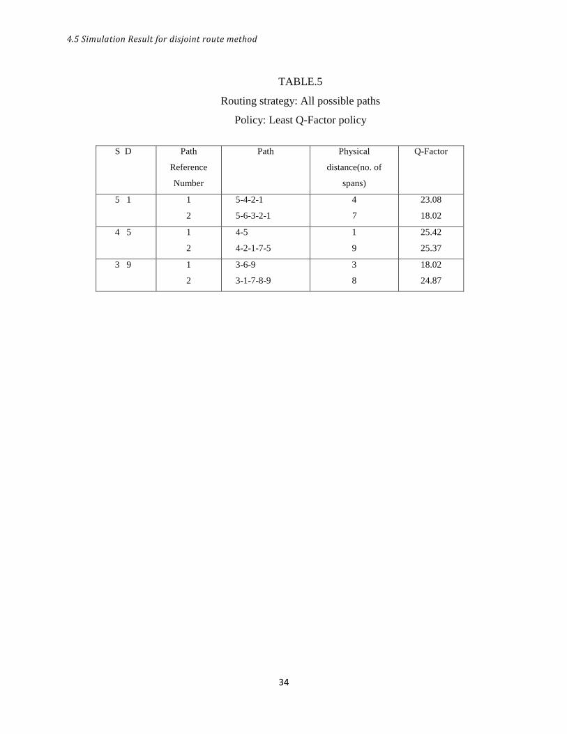
4.5 Simulation Result for disjoint route method
Fig 16, 17 shows the blocking probability for disjoint (all possible path) route where all
the routes between an s-d pair are pre-computed and stored in a routing table. The
blocking probability of Optimum-Q and SP are better compared to the LQ policy. This is
due to the fact that Optimum-Q chooses a path with highest Q-Factor from a set of
lightpaths. With increased route computation complexity the performance is similar to
alternate route and k-SP with further increase in the overall blocking probability. This is
due to that fact that selection of a longer path injects more crosstalk components into the
system which tend to lower the Q-Factor value of the already established call.
Fig.16 Blocking probability for disjoint route method when the number of
Wavelengths = 10
30 35 40 45 50 55 60 65 700
0.1
0.2
0.3
0.4
0.5
0.6
0.7
0.8
0.9
No of call requests
Blo
ckin
g p
rob
ab
ility
SP
Optimum-Q
LQ
4.5 Simulation Result for disjoint route method
33
Fig.17 Blocking probability for disjoint route method when the number of
Wavelengths = 12
Table 4, 5 gives the Q-Factor values for Optimum-Q policy and LQ policy. Q-Factor
values for paths selected using Optimum-Q policy are higher compared to LQ policy.
TABLE.4
Routing strategy: All possible paths
Policy: Optimum Q-Factor policy
S D Path
Reference
Number
Path Physical
distance(no. of
spans)
Q-Factor
7 8 1
2
7-8
7-1-2-3-6-9-8
1
11
19.88
27.32
4 5 1
2
4-5
4-8-7-1-3-6-5
1
12
33.50
25.83
1 7 1
2
3
1-7
1-2-4-5-7
1-2-3-6-5-7
4
6
9
28.57
22.55
36.33
30 40 50 60 700
0.1
0.2
0.3
0.4
0.5
0.6
0.7
0.8
No of call requests
Blo
ckin
g p
rob
ab
ility
SP
Optimum-Q
LQ
4.5 Simulation Result for disjoint route method
34
TABLE.5
Routing strategy: All possible paths
Policy: Least Q-Factor policy
S D Path
Reference
Number
Path Physical
distance(no. of
spans)
Q-Factor
5 1 1
2
5-4-2-1
5-6-3-2-1
4
7
23.08
18.02
4 5 1
2
4-5
4-2-1-7-5
1
9
25.42
25.37
3 9 1
2
3-6-9
3-1-7-8-9
3
8
18.02
24.87

35
CHAPTER 5
CONCLUSION AND FUTURE WORK
Conclusion
Future Work
5.1 Conclusion
36
CONCLUSION AND FUTURE WORK
5.1 Conclusion
The performance of different adaptive RWA algorithms has been evaluated in terms of
blocking probabilities in the presence of in-band crosstalk and ASE noise. Optimum-Q
policy shows better QoS performance compared to LQ and SP policies. With different
methods of route computation shortest path seems to provide reduced blocking
probability and reduced computational complexity compared to the other methods.
Although adaptive RWA algorithms are computationally intensive they are better suited
for the automatically switched optical networks.
5.2 Future Work
This work could be extended to include other linear and non-linear impairments to further
evaluate the blocking performance .We propose to improve upon the Q-Factor model
when non-linearity is included in the evaluation of the network performance.

37
BIBLIOGRAPHY
38
Bibliography
[1] S. Azodolmolky, M. Klinkowski, Eva Martin, Davide Careglio, Josep Pareta and
Ionnis Tomkos, ”A survey on physical layer impairments aware routing and
wavelength assignment algorithms in optical networks” , Computer Networks,
2009.
[2] J.C.Attard, J.E.Mitchell and C.J.Rasmussen, ”Performance analysis of
interferometric noise due to unequally powered interferers in optical networks”,
Journal of Lightwave Technology, vol.23, no.4, 2005.
[3] I. Tomkos, ”Performance Engineering of Metropolitan Area Optical networks
through Impairment Constraint Routing”, IEEE Communication, Mag. (Optical
Supplement), Aug 2004.
[4] Marcelo R.Jimenez, Rogerio Passy, Marco A. Grivet, J.P.Weid, ”Computation of
power penalties due to intra-band crosstalk in optical systems”, IEEE photonics
technology letters,vol.15,no.1,2003.
[5] Tao Deng and Suresh Subramaniam, ”Adaptive QoS routing in dynamic
wavelength routed optical networks”, Proceedings Broadnets, 2005.
[6] Rajiv Ramaswami, ”Optical fiber communication: From Transmission to
Networking”, IEEE Communications Magazine, 2002.
[7] G.P.Agarwal, ”Lightwave Technology Telecommunication Systems”, Wiley
Inter-Science, 2005.
[9] Saradhi and Subramaniam, ”Physical Layer Impairment Aware Routing (PLIAR)
in WDM optical networks: Issues and Challenges”, IEEE communications
surveys and tutorials, vol .11, no.4, 2009
[10] Santu Sarkar and Nikhil R Das, ”Study of component crosstalk and obtaining
detection threshold for minimum BER in a WDM receiver”, Journal of Lightwave
Technology, vol.27, no.19, 2009.
[11] Yvan Pointurier, Brandt-Pearce, Tao Deng and Suresh Subramaniam, ”Fair QoS-
aware adaptive routing and wavelength assignment in all optical networks”,
Proc.ICC, 2006.
39
[12] Y.Huang, ”Connection Provisioning with Transmission Impairment Consideration
in Optical WDM networks with High-Speed Channels”, IEEE/OSA Journal of
Lightwave Technol., vol.23, no.3, pp.982-993, Mar 2005.
[13] Dietrich Marcuse, ”Derivation of analytical expressions for the bit error
probability in lightwave systems with optical amplifiers”, Journal of Lightwave
Technology, vol.8, no.12, 1990.
[14] Yvan Pointurier and Brandt Pearce, ”Analytical study of crosstalk propagation in
all-optical networks using perturbation theory”, Journal of Lightwave Technology,
vol.23, no.12, 2005.
[15] P. Kulkarni, A. Tzanakaki, C. MasMachuka and I. Tomkos,”Benefits of Q-Factor
based routing in WDM metro networks”, ECOC 2005 Proc, vol.4.
[16] Yun feng Shen, K Lu and Wanyi Gu, ”Coherent and Incoherent crosstalk in
WDM optical networks”, Journal of Lightwave Technology, vol.17, no.5, 1999.
[17] Byrav Ramamurthy, Debasish Datta, Helena Feng, Jonathan P.Heritage,
Biswanath Mukerjee, ”Impact of Transmission impairments on the Tele-Traffic
performance on wavelength-routed optical networks”, Journal of Lightwave
Technology, vol.17, no.19, 1999.