ADAPTIVE GRAVITY BALANCING ARM SYSTEMS
91
Purdue University Purdue e-Pubs Open Access eses eses and Dissertations January 2016 ADAPTIVE GVITY BALANCING ARM SYSTEMS Harshal Upadhyay Purdue University Follow this and additional works at: hps://docs.lib.purdue.edu/open_access_theses is document has been made available through Purdue e-Pubs, a service of the Purdue University Libraries. Please contact [email protected] for additional information. Recommended Citation Upadhyay, Harshal, "ADAPTIVE GVITY BALANCING ARM SYSTEMS" (2016). Open Access eses. 1206. hps://docs.lib.purdue.edu/open_access_theses/1206
Transcript of ADAPTIVE GRAVITY BALANCING ARM SYSTEMS

Purdue UniversityPurdue e-Pubs
Open Access Theses Theses and Dissertations
January 2016
ADAPTIVE GRAVITY BALANCING ARMSYSTEMSHarshal UpadhyayPurdue University
Follow this and additional works at: https://docs.lib.purdue.edu/open_access_theses
This document has been made available through Purdue e-Pubs, a service of the Purdue University Libraries. Please contact [email protected] foradditional information.
Recommended CitationUpadhyay, Harshal, "ADAPTIVE GRAVITY BALANCING ARM SYSTEMS" (2016). Open Access Theses. 1206.https://docs.lib.purdue.edu/open_access_theses/1206

Graduate School Form 30 Updated 12/26/2015
PURDUE UNIVERSITY GRADUATE SCHOOL
Thesis/Dissertation Acceptance
This is to certify that the thesis/dissertation prepared
By
Entitled
For the degree of
Is approved by the final examining committee:
To the best of my knowledge and as understood by the student in the Thesis/Dissertation Agreement, Publication Delay, and Certification Disclaimer (Graduate School Form 32), this thesis/dissertation adheres to the provisions of Purdue University’s “Policy of Integrity in Research” and the use of copyright material.
Approved by Major Professor(s):
Approved by: Head of the Departmental Graduate Program Date
HARSHAL UPADHYAY
ADAPTIVE GRAVITY BALANCING ARM SYSTEMS
Master of Science in Mechanical Engineering
JUSTIN E. SEIPELChair
BRADLEY S. DUERSTOCK
ERIC A. NAUMAN
JUSTIN E. SEIPEL
JAY P. GORE 2/9/2016

i
i
ADAPTIVE GRAVITY-BALANCING ARM SYSTEMS
A Thesis
Submitted to the Faculty
of
Purdue University
by
Harshal Upadhyay
In Partial Fulfillment of the
Requirements for the Degree
of
Master of Science in Mechanical Engineering
May 2016
Purdue University
West Lafayette, Indiana

ii
ii
TABLE OF CONTENTS
Page
LIST OF TABLES .................................................................................................................... iii LIST OF FIGURES .................................................................................................................. iv ABSTRACT………………………………………………………………………………………………………………………vi CHAPTER 1. INTRODUCTION ......................................................................................... 1
1.1 Motivation ................................................................................................................. 2
1.2 Scope of Research ..................................................................................................... 3
1.3 Problem Statement ................................................................................................... 3
CHAPTER 2. RELEVANT BACKGROUND and LITERATURE REVIEW ................................ 4
2.1 Passive, Spring-Based Gravity-Balancing Arms ......................................................... 4
2.2 Overview of Existing Devices ..................................................................................... 7
2.2.1 Passive Arm Devices ...................................................................................... 7
2.2.2 Adjustment Mechanism Concepts ................................................................ 9
2.2.3 Active/Semi-Active Devices ........................................................................ 15
2.3 Summary ..................................................................................................................... 16
2.4 Current Gap ................................................................................................................. 17
CHAPTER 3. MECHANICAL DESIGN .............................................................................. 19
3.1 Adaptive Arm Device Overview ............................................................................... 20
3.2 Mechanical Design of System Components ............................................................ 28
3.2.1 Need for Low Natural Frequency ................................................................ 28
3.2.2 Design of Linkage Structure ........................................................................ 30
3.3 Design of the Actuator ........................................................................................... 38
CHAPTER 4. LOAD ADAPTION MODE .......................................................................... 46
4.1 Desired Equilibrium Position ................................................................................... 46
4.1.1 Experiment to Find Natural Frequency ....................................................... 47
4.1.2 Results ......................................................................................................... 48
4.2 Load Adaption Controller ........................................................................................ 51
4.3 Load Adaption Mode Testing .................................................................................. 59
4.4 Human-Centered Framework for Evaluating Load Adaption .................................. 65
CHAPTER 5. POSITION ADAPTION MODE ................................................................... 69
5.1 Position Adaption Controller ................................................................................... 69
5.2 Results ..................................................................................................................... 71
CHAPTER 6. CONCLUSIONS ......................................................................................... 75
LIST OF REFERENCES ......................................................................................................... 79

iii
iii
LIST OF TABLES
Table .............................................................................................................................. Page 3.1: Components & their working. ................................................................................... 22
3.2: Design parameters and their effects on natural frequency. ..................................... 30
3.3: Spring specifications. ................................................................................................. 31
3.4: Max ‘a’ value and corresponding possible load support values. ............................... 34
3.5: Motor specification. ................................................................................................... 41
3.6: Components and system qualities. ............................................................................ 43
3.7: Component summary and cost approximation. ........................................................ 44
4.1: Natural frequency vs load. ......................................................................................... 49
4.2: Gain values and operating ranges. ............................................................................ 57
iv
iv
LIST OF FIGURES
Figure ............................................................................................................................ Page 2.1. Various parameters in linkage spring type balancer. .................................................. 5
2.2. Force vectors on the linkage-spring type balancer. ..................................................... 6
2.3. Adding load to the system. ....................................................................................... 10
2.4. Schematic diagram for ‘r’ type adjustment method.Change in ‘r’ as mass changes. 11
2.5. K-type adjustment method. ....................................................................................... 12
2.6. ‘a’-type adjustment method. Change in ‘a’ as mass changes. .................................. 13
2.7. ‘a’ and ‘r’ simultaneously adjusted. ........................................................................... 14
2.8. Current gap. (a) Existing manual arm systems. (b) Existing user controlled arm systems. (c) Proposed adaptive arm system. ............................................................ 18
3.1. Arm device assembly and CAD model rendering. ..................................................... 20
3.2. Adaptive arm device assembly. ................................................................................. 21
3.3. Operating modes of the adaptive arm device. .......................................................... 23
3.4. Controllable parameters. ........................................................................................... 24
3.5. Working of the passive arm mode. ............................................................................ 25
3.6. Working of load adaption mode. ............................................................................... 26
3.7. Working of the position adaption mode. .................................................................. 27
3.8. Schematic for gravity balancing device. .................................................................... 30
3.9. Design and drawings of the linkages. ........................................................................ 33
3.10. Range of motion of the links. (a) 0 to -68 deg. (b) 0 to +70 deg. ............................. 35
3.11. Shaft dimensions (inches). ....................................................................................... 36
3.12. FEA analysis of the shaft where spring attaches to the linkage structure. ............. 36
3.13. Actuator assembly and CAD rendering. ................................................................... 38
3.14. Lead screw dimensions. ........................................................................................... 40
3.15. Torque vs speed DC motor. ..................................................................................... 42
4.1. Schematic for the arm device and equivalent spring mass system. .......................... 47
4.2. Natural frequency vs load. ......................................................................................... 49
4.3. Varying natural frequency at different angular positions. ........................................ 50
4.4. (a) Triangle relating different parameters (b) Forces acting on the mechanism. ..... 52
4.5. Simulink model of the arm device. ............................................................................ 54
4.6. Open loop response comparison. .............................................................................. 54
4.7. General feedback control loop. ................................................................................. 56
4.8. Gain schedule approach. ........................................................................................... 57
4.9. Load adaption control loop for the experimental setup. .......................................... 58

v
v
Figure Page 4.10. Response of the adaptive system with slower gains, without damping and initial
arm weight. .............................................................................................................. 60
4.11. Response of the system with damping, initial arm weight and faster gains. .......... 62
4.12. Adjustment time (sec) vs load (lbs.) comparison with slower gains (no damping and arm weight) and faster gains (human arm weight and damping). ................... 63
4.13. Repeatability of the load adaption mode. ............................................................... 64
5.1. Control loop for position adaption mode. ................................................................. 71
5.2. Experimentally measured desired ‘a’ value for statically balancing the given load at varying link angular positions. ............................................................................... 72
5.3. Measured angular velocity of the links vs load mass. ............................................... 73
6.1. Comparison between arm systems based on adjustment type and user interaction. The placement of existing devices on this figure is based on the author’s qualitative assessment of each device. Here, “manual adjustment” is used to mean that the user physically interacts to either directly adjust the mechanism or via a controller joystick or setting knob. In either case, this manual adjustment requires prolonged interaction and user decision making about the adjustment of the device. ......................................................................................... 77

vi
vi
ABSTRACT
Upadhyay, Harshal. M.S.M.E., Purdue University, May 2016. Adaptive Gravity-Balancing Arm Systems. Major Professor: Justin Seipel, School of Mechanical Engineering. Gravity balancing arms are passive weight support mechanisms that have been used to
support human arms when weakened or otherwise in need of assistance. However, these
systems could be greatly enhanced for everyday use if they can adapt for changing load
mass or position. This thesis presents the development and preliminary testing of an
adaptive system for gravity balancing arm devices that requires minimal user involvement
and has low power and sensing requirements since it is built upon the system’s passive
dynamics. It uses active control only to re-equilibrate the underlying passive system for
changing conditions, then is turned off when not needed. Users can go about everyday
tasks, and as a load mass or position for their task changes, they simply switch the system
into an adaptation mode for either load mass or position, and the system takes care of
the rest. The controller uses an indirect and low-power actuation method, adjusting the
position of a key passive spring parameter (‘a’ value). The system requires only one
sensor, an encoder, to measure the angle of the gravity balancing arm, which is used to
indicate position of the gravity balancing arm. We use gain scheduling feedback control
due to the nonlinearity of the gravity balancing arm system. Here, we primarily seek to

vii
vii
demonstrate the feasibility of this novel system design. However, we also experimentally
measure the adaptation response of the system for multiple load masses and two
versions of the control gains (one for minimal damping to reduce energy cost, and one
with increased damping effect to improve response times). We seek response times that
are fast enough for the user to maintain task memory (2-4 seconds), but not significantly
faster to keep power, weight, and actuator cost lower. We confirm that the system meets
this objective by quantitatively measuring response times for each trial and providing a
qualitative analysis of the system effectiveness based upon user-centered requirements
from the field of user-interface design. Overall, we find that the system initiates physical
adaptation changes fast enough to be perceived as continuous with the user’s task (less
than 1 second), and can complete adaptation fast enough for users to maintain task
memory (2-4 seconds) when load masses are less than 7.5 lbs.

1
1
CHAPTER 1. INTRODUCTION
Arm support devices have been effectively used across a broad range of
applications ranging from assistive support and rehabilitation of weakened arms, to
camera operation and tool use. Passive gravity balancing techniques have found
particularly good application to help people suffering from neuromuscular weaknesses
who have difficulties in lifting and maneuvering their arms against gravity. Besides
assisting them in performing various tasks and activities of daily living (ADL), these devices
have also attempted to improve their independence. However, despite advancements in
newer designs for arm support devices, their usage in changing conditions like loads and
positions remains limited.
In day-to-day life, human arms interact with varying load masses. From a task of
handling smaller loads like that of a coffee cup or laptops to dealing with relatively larger
loads like lifting a travel bag; a healthy human arm adapts to changes in loads and
positions naturally. However, for a person suffering from neuromuscular weakness,
dealing with varying loads and positions can be challenging and exhausting. Thus, there
arises a need for improving the present class of arm support devices. Currently, it remains
unknown exactly how passive arm devices can be made to respond automatically to

2
2
changing conditions of loads and positions. The primary objective of this work is to
improve the current class of arm devices by developing adaptive systems.
1.1 Motivation
More than a million people in United States are affected by some form of
neuromuscular disease. Being progressive in nature, many of these diseases result in
muscle weakness and fatigue. Many people with this condition in the arms face challenges
in daily life. These challenges vary from lifting arms against gravity to decreased range of
motion, to difficulties in performing activities of daily living and to overall increased
dependency on other people. In order to overcome these challenges, assistive arm
support devices are desired. A lot of advancement has been made in developing gravity
balancing mechanisms for arm devices. These have particularly lead to assistance in
balancing the arm weight against gravity and have attempted at improving range of
motion. However, assistance in performing activities of daily living in a dynamic
environment, and intuitive use of the assistive device, as well as more complete
independence, remain challenges that still require reliable solutions.
The motivation behind this thesis lies in expanding and improving the utilities of the
existing class of gravity-balancing arm devices in order to assist in overcoming the
challenges faced by current users. An adaptive system is proposed to achieve device
adjustment and adaptability for varying load masses and positions, while attempting to
maintain the overall system reliability and cost near current passive gravity-balancing
systems.

3
3
1.2 Scope of Research
This thesis focuses on implementing an adaptive system for gravity-balancing arm
support devices. The scope of this research spans from existing literature to controls
approaches in developing adaptive control, as well as testing of the device. A
comprehensive review of the existing arm mechanisms is performed to understand the
existing designs and qualities of these devices. Based on this review, an assistive arm
setup is designed and manufactured which is used for implementing and testing of the
proposed adaptive system approach. Currently, system adaptation responses and
performance are analyzed via non-human testing of the device, using system
performance metrics from user-interaction design that do not require human testing at
this time. For future testing of hypotheses involving overall human-device interaction,
the current experimental platform may be extended to include human subject testing.
1.3 Problem Statement
The specific research objective of this thesis is to:
Develop an adaptive gravity-balancing arm system by implementing a closed loop
controller enabling the device to automatically adapt to changing load mass and position.

4
4
CHAPTER 2. RELEVANT BACKGROUND AND LITERATURE REVIEW
This chapter begins with a discussion of the basic passive, spring-based gravity-
balancing arm designs and different parameters which are important for adjustment.
Next, currently available gravity-balancing arm devices are discussed. We discuss how
these passive devices are improved to extend their applications in assistive tech, rehab,
and industrial fields. Further, the need for adjustment is highlighted, including current
attempts to address this involving energy-free adjustment designs and user-controlled
power assist systems. The chapter concludes with a discussion of the limitations of
present systems.
2.1 Passive, Spring-Based Gravity-Balancing Arms
In order to understand different design criteria for arm mechanisms, a basic
understanding of the gravity balancing theory behind the passive, spring-based designs is
necessary. A schematic diagram shown in Figure 2.1. indicates how a linkage type
balancer is balanced using spring attachment across the structure. Detailed explanation
of such designs can also be found in the work by Van Drunen [1].

5
5
Figure 2.1. Various parameters in linkage spring type balancer.
Different parameters used in this concept are:
a : The vertical distance between the linkage pivot point and spring attachment.
r : Distance between linkage pivot point and attachment at other end of spring.
k : Stiffness of the spring.
L : The length of the linkage
m : Total mass
g : Acceleration due to gravity
The balancing equilibrium in such designs can be understood by a simple force analysis as
shown in Figure 2.2.
6
6
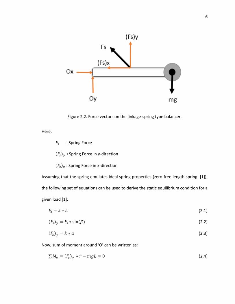
Figure 2.2. Force vectors on the linkage-spring type balancer.
Here:
𝐹𝑠 : Spring Force
(𝐹𝑠)𝑦 ∶ Spring Force in y-direction
(𝐹𝑠)𝑥 : Spring Force in x-direction
Assuming that the spring emulates ideal spring properties (zero-free length spring [1]),
the following set of equations can be used to derive the static equilibrium condition for a
given load [1]:
𝐹𝑠 = 𝑘 ∗ ℎ (2.1)
(𝐹𝑠)𝑦 = 𝐹𝑠 ∗ sin(𝛽) (2.2)
(𝐹𝑠)𝑦 = 𝑘 ∗ 𝑎 (2.3)
Now, sum of moment around ‘O’ can be written as:
∑𝑀𝑜 = (𝐹𝑠)𝑦 ∗ 𝑟 − 𝑚𝑔𝐿 = 0 (2.4)

7
7
𝑚𝑔𝐿 = 𝑎𝑘𝑟 (2.5)
Equation (2.5) holds true for any angle and a given fixed load under the condition that the
spring follows ideal spring properties.
2.2 Overview of Existing Devices
The majority of current gravity-balancing arm devices can be divided into two
categories: a) Passive Devices, or b) Active/Semi-active Devices. Most of the Passive
devices are based on the concept of static gravity balancing using springs. These are
intended for users who have reduced muscle functionality, but maintain a significant
degree of arm function. Active/Semi-active devices are mainly intended for users who
have very weak arms and who in some case do not have much muscle force. These active
devices generally use continuous actuators to assist or do task for the user. Both classes
of devices have found application not only in assistive or rehab applications but also in
work-related applications like load lifting and carrying.
2.2.1 Passive Arm Devices
Passive arm devices have found use in several fields.
Assistive Applications: Early devices like the one by Rahman et al. [2] used gravity
balancing approaches involving passive springs. Designed to use bungee cords as springs
to support “arm floatation,” this device yielded insights into the design and construction
of gravity-balancing mechanisms.

8
8
This device was found to support the user’s arm well. However, size and attachments
were big concerns which perhaps limited the use in further practice.
A more commercially available passive device Wilmington Robotic Exoskeleton
(WREX) [3], was then developed as an improved version of the previously discussed
device [2]. With the objective of providing a sense of flotation to the arm of the user,
WREX is a more compact device. Intended for applications for children with
arthrogryposis, the WREX can assist in 3D movements in a low-profile exoskeleton
structure. By using elastic bands across the linkage structure, WREX provides gravity
compensation. However, the device doesn’t account for any changes in mass. For
different loads, the elastic bands will require changing. This makes the device mostly
suitable only for a fixed load.
Similarly, another commercially available device is the TOP-help [4]. The TOP-help
is designed for people who have at least some functionality of the hand. The device uses
gravity compensation method using elastic component like in the WREX [3]. It has
improved systems of axes with several rotation points. Through the axes system, TOP-
Help provides improved movements to the supported arm. With a manual adjustment
method, the user can adjust the device for different levels of support.
Load Support Applications: Various commercially available passive arm mechanisms have
also found applications in tool operations and camera stabilization. Devices like Equipoise
ZeroG [5] have been aimed at reducing injuries and increasing productivity of the workers
by supporting various tools and assisting them in maneuvering parts.

9
9
Similarly, by applying gravity balancing mechanisms to both linkages, the Steadicam [6] is
used for stabilizing the camera operations.
Rehabilitation Applications: Devices like the SAEBO mobile arm [7] have found
application in rehabilitation for elderly. By using compact spring and a pulley systems
fitting inside the linkage structure, it can provide different levels of support for patients.
The therapist monitors the progress of the patient and manually changes the support
requirements for different exercises.
The discussed passive devices have enabled compliant support. Improved designs
have also extended their use in various application fields. These devices seem to work
well when there is fixed load support. However, passive devices have limitations when
the user has to interact with changing loads. Manual knobs, screws and lever are present
in these devices to increase or decrease the support. But this would require a lot of user
effort and will be time consuming. Thus, to improve upon that, some of the newer current
devices use improved adjustment systems.
2.2.2 Adjustment Mechanism Concepts
In order to develop mechanisms which adapt to the changing load mass,
understanding the basic concepts on which they are based upon is necessary. Based on
different parameters discussed in section 2.1, the gravity balancing equation can be re-
arranged
𝑚𝑔 = (𝑎𝑘𝑟)/L (2.6)

10
10
If there is addition of mass, the system goes out of balance causing a downward motion
of the linkage, as shown in Figure 2.3.
Figure 2.3. Adding load to the system.
If we closely examine Equation (2.6), a new equilibrium can be established only if
parameters ‘a’, ‘r’, ‘k’ or ‘L’ are changed to account for changing mass ‘m’. Classification
based on these parameters found in [1] gives good insights on feasible methods in
developing adjustment systems.

11
11
‘r’ type Adjustment
Figure 2.4. Schematic diagram for ‘r’ type adjustment method. Change in ‘r’ as mass changes.
Varying the distance ‘r’ changes the moment arm of the force acting on the bar.
The support provided can be increased or decreased by changing ‘r’. This type of
adjustment has a major challenge in implementation. Since the adjustment mechanism
will need to be on the moving linkage, the overall weight of the linkage is increased. The
device now needs to support both the added load ‘m’ and the mass of the ‘r’ type
adjustment mechanism. Besides that, the design also needs to account for the
movements of the adjustment mechanism itself, which could be complicated to
implement.
M
r r
m
12
12
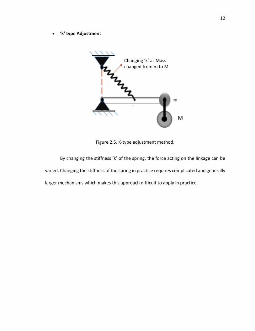
‘k’ type Adjustment
Figure 2.5. K-type adjustment method.
By changing the stiffness ‘k’ of the spring, the force acting on the linkage can be
varied. Changing the stiffness of the spring in practice requires complicated and generally
larger mechanisms which makes this approach difficult to apply in practice.
Changing ‘k’ as Mass changed from m to M

13
13
‘a’ type Adjustment
Figure 2.6. ‘a’-type adjustment method. Change in ‘a’ as mass changes.
By increasing the vertical distance ‘a’, the vertical component of the spring force
acting on the linkage can be increased. This type of adjustment is positioned on to a fixed
place and is in a static environment unlike ‘r’ type. Thus, all the available energy can be
used in much better way than both ‘r’ and ‘k’ type adjustments. The ease of
implementation makes this method most suitable to use in practice. This understanding
of the adjustment concepts has been implemented in current devices. SAEBO arm,
Steadicam, Equipoise ZeroG use manual ‘a’ type adjustments. TOP-help uses ‘r’ type
adjustments and WREX uses ‘k’ type adjustment (adding or reducing the elastic bands).
However, all of these passive adjustments require user effort and some are found
to be fatiguing [9]. In order to improve upon that, methods are currently being developed
which adjust the system to different loads in an energy-free fashion [8].

14
14
Energy Free-Adjustment mechanisms
Simultaneous Displacement Method (SD): In this method, ‘a’ and ‘r’ are simultaneously
adjusted in such a way that the spring length remains the same. This means no work is
required as the spring energy is constant.
Figure 2.7. ‘a’ and ‘r’ simultaneously adjusted.
However, the product of ‘a’ and ‘r’ does varies, which re-establishes spring balance for a
new load. This concept was implemented by TOP-Help [9] device. In this, a handle is
provided in the mechanism to manually change the settings. Although this approach
requires lower operating efforts; over longer durations this method was found to be
fatiguing by some users [9]. Besides that, increased mechanical complexities have made
the overall device larger.
Storage Spring Method: The storage spring method makes use of an additional spring that
provides the energy needed for adjustment of the spring balancer [10]. This method
provides lower operating effort at the expense of increased mechanical complexities (2
balancers).
m r
a
m m

15
15
Virtual Spring Method : This method works by replacing the single zero-free-length spring
of the basic static balancer by substituting 2 zero-free-length springs with properties
based on a virtual spring with similar spring properties as the initial spring [11]. By using
a pantograph design, the virtual spring is adjusted without external energy.
Another such method is discussed in [11] where stiffness is adjusted in an energy-
free fashion. Thus, these passive adjustment methods have enabled adjustments to
changing loads with low operating energy. However, all of these methods can adjust the
mechanism in an energy-free fashion only in one position. For other configurations, the
user effort can be considerable. Besides that, the added mechanical complexity makes
devices bulkier and more complicated to operate.
2.2.3 Active/Semi-Active Devices
In order to make adjustment mechanisms more suitable for arm devices, some
commercially available devices have provided user controlled power assists to reduce
user efforts for adjustment along with compact designs which can provide easy
adjustment for any position. For assistive applications, ArmOn [12] and Gowing’s dynamic
arm [13] have provided user-controlled power assist features for leveling and variations
in support.
Users can operate a switch to increase or decrease the support according their
preferences. Another device using this kind of approach is the Dynamic Arm Support (DAS)
by Exact dynamics [14]. A compact vertical lift mechanism is used to provide power assist

16
16
for the user [15]. The users can increase or decrease the compensation force via controller
on the wheel chair.
2.3 Summary
Above, multiple mechanism types and the existing state of the art were reviewed.
In summary, the passive designs and mechanisms have enabled compliant support and
assistance to people with weakened arm muscles. With features enabling lower operating
force around a given equilibrium, these passive devices are useful in many applications.
However, these designs were not made to react to varying conditions (mass and position).
This issue was addressed by the development of some energy-free passive
adjustment mechanisms. These mechanisms adjusted the device to varying load masses
with low operating energy. However these required frequent human interaction like
changing knob settings, screw adjustments or lever shifts to conduct these adjustments.
These approaches were thus found to be either too fatiguing by the users, or included
larger/complex mechanical systems which made the whole device larger in size or limited
some range of motion.
User-controlled power-assist approaches were found in basic forms in a few of the
devices. In these methods, the inherent advantage is that the devices require relatively
less power and cost than the fully active ones. Semi-active methods also cover up on the
limitations of the fully passive methods by having easier adjustment methods, more
independent usage and longer duration of use with a compact design. Thus, in order to
have a system with improved behaviors and qualities along with overall reliability, the

17
17
active/semi-adaptive approach was concluded to be the most suitable approach to
implement.
2.4 Current Gap
The current devices which use active/semi-active designs have improved upon
some interactions and helped in assisting many ADLs (Activities of Daily living). Some have
attempted to address issues with user involvement with adjustments and have provided
user control using buttons and controllers. However, these are open loop systems, and
have left the decision making for system adjustment/tuning to the user. The targeted
users for these devices already face decreased arm functionalities.
Asking the user to conduct all the adjustments and involved decision making could
make the device exhausting [9] and non-intuitive to use. Moreover, some of these
adjustments may not be optimum and might require the user to keep making multiple
adjustments. Thus, in order to improve arm support devices for changing conditions like
varying loads and positions, there arises a need for developing an approach which could
not only make these arm devices easily and rapidly adjustable to any changing condition
but also do it in a reliable automatic manner. Figure 2.8 shows this current gap by
depicting the existing state of the art concepts (manual & user controlled) and the
proposed adaptive arm concept.

18
18
Figure 2.8. Current gap. (a) Existing manual arm systems. (b) Existing user controlled arm systems. (c) Proposed adaptive arm system.
The next part of this thesis proposes a design approach for developing and testing
an adaptive gravity-balancing arm that will automatically adapt for changing load mass or
position.

19
19
CHAPTER 3. MECHANICAL DESIGN
This chapter first introduces the proposed adaptive gravity-balancing arm device. An
overview of the design parameters, components and the working modes of this system
are then given. Once the overview is established, the Mechanical Design and the
Controller designs are discussed.
In order to develop an overall reliable arm device, multiple factors are considered.
In particular, we identified the following design targets: 1) adaptability to changing
environment (including changing load mass or load position), 2) ease of operation, 3)
intuitive use, 4) compactness, 5) low power, and 6) low cost.
The overall approach used here is to develop a system which builds upon and
extends the positive qualities of passive-based gravity balancing arm systems [17] as
these systems already meet most of the design criteria listed here. However, this would
require the addition of a low power, intuitive automatic adjustment system, integrated
with the passive dynamics of the underlying system. The proposed design follows:

20
20
3.1 Adaptive Arm Device Overview
A prototype of the proposed adaptive arm device is shown in Figure 3.1. The objective
behind designing such a system is to enable existing gravity balancing arm devices to
adapt to changing loads and positions. In addition to standard passive elements of gravity
balancing arms, a new controller, sensor, and actuator are integrated to enable user-
initiated automatic adaptability of the system for changing loads or positions.
Figure 3.1. Arm device assembly and CAD model rendering.
The multiple components of the arm device, including the new active elements, are
shown in Figure 3.2.

21
21
Figure 3.2. Adaptive arm device assembly.
The 2 major components of the arm device assembly in Figure 3.2 are:
A) The Actuator System: This includes 1) DC motor with encoders, 2) Linear Drive
System, and 3) Pre tensed spring.
B) The Linkage System: This includes an 4) Encoder on the arm link, a 5) Load cell, 6)
Switches, 7) human arm attachment, and 8) Rigid links.
Each of these components play an important role in the overall functionality of the device.
Table (3.1) shows an overview of the role of each component in the working of the
adaptive arm device.
Act
uat
or
Lin
kage
Str
uct
ure
8
22
22
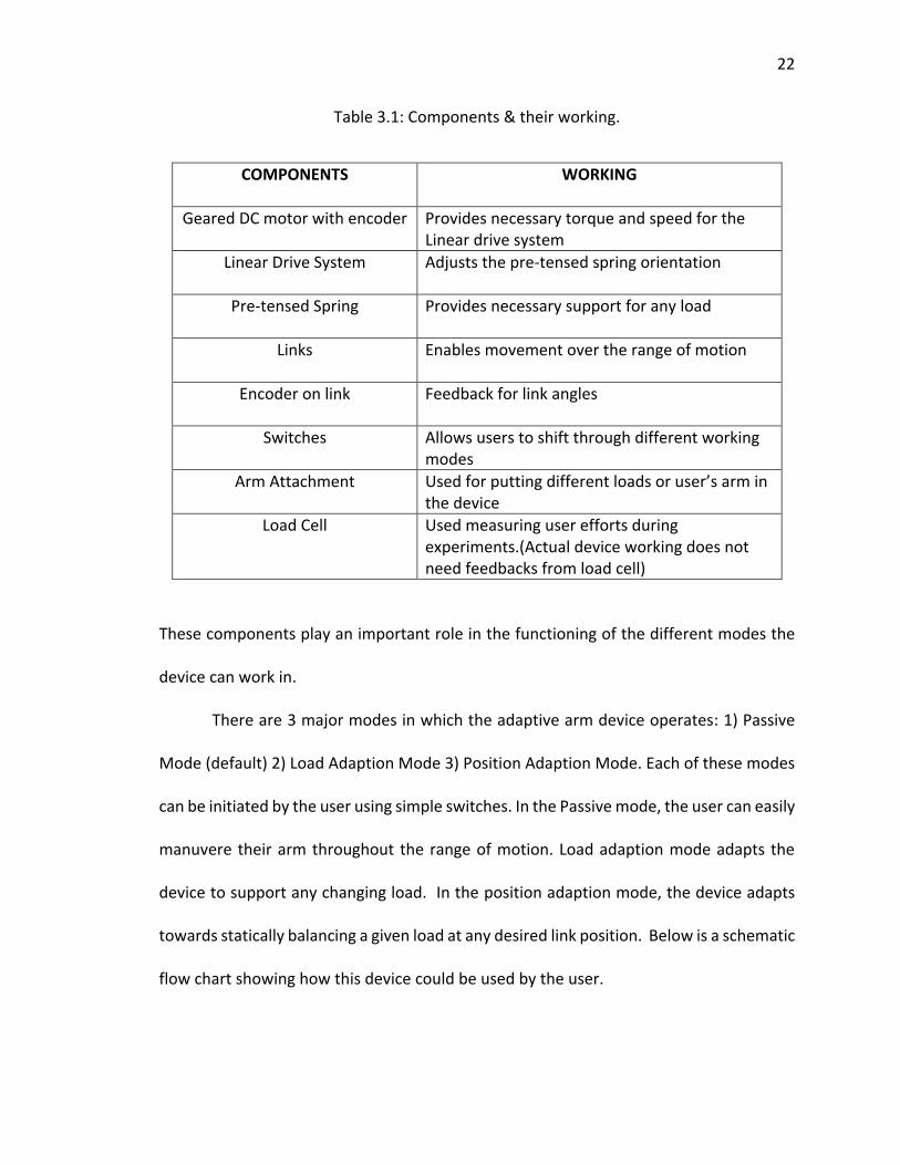
Table 3.1: Components & their working.
COMPONENTS WORKING
Geared DC motor with encoder Provides necessary torque and speed for the Linear drive system
Linear Drive System Adjusts the pre-tensed spring orientation
Pre-tensed Spring Provides necessary support for any load
Links Enables movement over the range of motion
Encoder on link Feedback for link angles
Switches Allows users to shift through different working modes
Arm Attachment Used for putting different loads or user’s arm in the device
Load Cell Used measuring user efforts during experiments.(Actual device working does not need feedbacks from load cell)
These components play an important role in the functioning of the different modes the
device can work in.
There are 3 major modes in which the adaptive arm device operates: 1) Passive
Mode (default) 2) Load Adaption Mode 3) Position Adaption Mode. Each of these modes
can be initiated by the user using simple switches. In the Passive mode, the user can easily
manuvere their arm throughout the range of motion. Load adaption mode adapts the
device to support any changing load. In the position adaption mode, the device adapts
towards statically balancing a given load at any desired link position. Below is a schematic
flow chart showing how this device could be used by the user.

23
23
Figure 3.3. Operating modes of the adaptive arm device.
While doing a task, the arm device can be operated by the user as shown in Figure 3.3.
Tasks requiring support for changing conditions like load and position could be done using
the adaption modes. Both of the adaption modes are automatic in nature and require
minimal user interference. Tasks requiring free movement of a constant supported load
could be done using the passive mode. A user can shift between the various modes just
by using switches to initiate the modes. This requires less user involvement than manually
adjusting the system or manually setting control knobs or joysticks to adjust the system.
Before discussing the working of these modes in detail, it is necessary to
understand the parameters which have a significant impact on the adaptive modes.
24
24
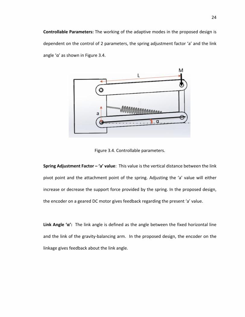
Controllable Parameters: The working of the adaptive modes in the proposed design is
dependent on the control of 2 parameters, the spring adjustment factor ‘a’ and the link
angle ‘α’ as shown in Figure 3.4.
Figure 3.4. Controllable parameters.
Spring Adjustment Factor – ‘a’ value: This value is the vertical distance between the link
pivot point and the attachment point of the spring. Adjusting the ‘a’ value will either
increase or decrease the support force provided by the spring. In the proposed design,
the encoder on a geared DC motor gives feedback regarding the present ‘a’ value.
Link Angle ‘α’: The link angle is defined as the angle between the fixed horizontal line
and the link of the gravity-balancing arm. In the proposed design, the encoder on the
linkage gives feedback about the link angle.
α
a
L M

25
25
Operation of different modes: The proposed system has three different operational
modes, as follows:
1) Passive Mode: This is the default mode which supports just the user’s arm
weight or a fixed load. In this mode, the user can maneuver their arm freely throughout
the range of motion. This mode should be the preferred mode to use when the user feels
the device can support the load weight. Figure 3.5 shows a user maneuvering the arm
through different angular positions. The spring adjustment paramer ‘a’ remains constant
in this mode. Also the actuator assembly remains off as the motor is not required to adjust
any parameter during this mode of operation.
Figure 3.5. Working of the passive arm mode.

26
26
2) Load Adaption mode: The user should switch to the load adaption mode during
tasks where load changes are required. In day to day life, this can be anything such as
dealing with smaller changing loads like a coffee cup, a laptop, or dealing with relatively
larger changing loads like lifting a bag. This can even be used in industrial applications,
where a worker might need to work with different types of changing tools. Figure 3.6
shows the working of the load adaption mode. Initially, the device is statically balanced
at the horizontal link position wihtout any external load. Once the device senses a change
in link angle caused by a change in external load, then the actuator starts adjusting the
spring parameter ‘a’ in order to re-establish the initially desired equillibirum position of
the links.
Figure 3.6. Working of load adaption mode.

27
27
3) Position Adaption Mode: This mode can be used when the user needs support
at different link positions while using the arm device. The spring support in passive mode
reduces as the link angles increase. Which means that users with very weak arm muscles
might still face difficulties in reaching higher link positions. In the position adaptation
mode, the device provides constant support throughout the range of motion. It adapts to
any new equilibrium link position with the current load mass. Figure 3.7 shows the
working of this mode. The user moves a given load to a different link position. As the link
angles change, the controller adjusts the ‘a’ value continuously in order to establish a new
equilibrium at the changed position. Thus, the device can statically balance a given load
at any link angle.
Figure 3.7. Working of the position adaption mode.

28
28
In the proposed system, the user can switch between the 3 modes by pressing a single
switch. This makes operating the device dependent only on the user to initiate adaptation,
but no other control effort is required, thus requiring less operating effort and less time
than manual adjustment or user-controlled adjustment.
3.2 Mechanical Design of System Components
Each component of the adaptive arm device is designed based on various criteria. Some
of the decisions regarding the mechanical design of the components are based on the
analysis of the existing arm designs.
3.2.1 Need for Low Natural Frequency
One of the important desirable features in the device is low operating force to position a
load around a desired equilibrium position. Previous work on passive stabilizing arm
design [17] has provided good insights on many design parameters which lead to low
operating effort for the users. In order to have very low operating force for the user, the
device should have low mechanical impedance. Mechanical impedance is the measure of
system’s resistance to motion when subjected to harmonic force [18]. It is also the ratio
of force divided by velocity in frequency domain. For a spring mass damper system, the
impedance and its magnitude for a single degree of freedom is
𝑍 = (𝐾
𝑠) + 𝐶 +𝑀𝑠 (3.1)
|𝑍| = √𝐶2 + (𝑀𝜔 −𝐾
𝜔)2 (3.2)

29
29
Equation (3.1) and Equation (3.2) show that mechanical impedance is also dependent on
the effective stiffness, damping and mass. Thus, for a system to have lower mechanical
impedance, the effective stiffness and damping should be minimized.
Effective stiffness of a spring mass system is also related to the natural frequency as
𝜔𝑛 = √𝐾
𝑀 (3.3)
It can also be represented in terms of spring extension as
𝜔𝑛 = √𝑔
∆𝑥 (3.4)
From Equation (3.3), it can be understood that, lower effective stiffness can be obtained
by making natural frequency of the system lower. From Equation (3.4), it is clear that for
lower natural frequency, the effective spring deflection needs to be large. Thus it can be
established that for lower operating force it will be advantageous to have lower natural
frequencies in the system. This can be achieved by having very large spring travel length
or by using mechanical advantage [17]. Because conventional springs are not capable of
very long deflections, many mechanisms use mechanical advantage. The passive arm
mechanisms [17] use such mechanical advantage to reduce the natural frequency of the
system. As discussed in Section 2.1, various parameters of a gravity balancing arm design
like spring stiffness ‘k’, link length ‘L’, vertical distance ‘a’ and spring free length have
effects on the natural frequency of the system.
A summary of effects that different parameters have on the natural frequency of
the device is shown below in Table 3.2 (based on work presented in [17]).

30
30
Table 3.2: Design parameters and their effects on natural frequency.
Parameter Effect
Spring Stiffness ‘ k’ Increasing the ‘k’ value increases the range of load the device can support. However, there is no significant effect on the natural frequency of the system.
Adjustment value ‘a’ Increasing the ‘a’ value, increases the natural frequency. Lower natural frequencies are found at lower ‘a’ values.
Linkage length ‘L’ Shorter link lengths ‘L’ are able to support higher loads. However the natural frequency of the device is increased as a result.
Spring free length ‘l0’ Decreasing the spring free length makes the device support larger loads along with reducing the natural frequency
3.2.2 Design of Linkage Structure
Based on this understanding and the desired qualities in the system, a set of design
requirements are prepared. The arm device setup is based on the existing gravity
balancing design as shown in the schematic below.
Figure 3.8. Schematic for gravity balancing device.

31
31
Load support: Design of various components of the arm device setup is dependent on the
range of load that is intended for support. Since the work here is aimed at assistive or
rehabilitative applications, the load support range is chosen to be lower, from 0-20lbs, as
opposed to the higher loads that might be present in a worker application.
Spring selection: Based on the load support criteria of 0-20lbs, and the goal of reducing
mechanical impedance and natural frequency as discussed above, a spring with the
following specification is chosen [19]:
Table 3.3: Spring specifications.
Spring Type Extension Spring
OD(in) 1.0
Length(in) 6.50
Stiffness ‘k’ (lbs./in) 34.00
Wire Dia (in) 0.1480
Material Music Wire
Max Deflection (in) 3.100
Max Load(lbs) 114.00
Initial Tension (lbs) 10.00
32
32
Linkage Structure design: A parallel linkage structure is chosen for the arm device set up.
The linkage lengths are dependent on the pre-stretched length of the spring. As
discussed in Section 3.2.1, decreasing the free length of the spring ‘l0’ increases the load
support range and also decreases the natural frequency of the device. In order to
decrease the free length of spring, an extension spring can be pre-stretched [1]. This is
better understood from the following equations. In an extension spring let l0 be free
length , L0 be initial length and𝐹0 be initial tension ; then spring force equations can be
written as below.
𝐹0 = 𝐾(𝐿0 − 𝑙0) (3.5)
𝐹0 = 0 (3.6)
𝑙0 = 𝐿0 (3.7)
From Equation (3.5) it is clear that for 𝐹0>0, the free length 𝑙0 < 𝐿0 . Further if the initial
tension 𝐹0 is made equal to 𝐾𝐿0 then the initial free length 𝑙0 can be made zero. This will
make the spring emulate ideal spring properties where𝐹 = 𝐾𝐿.
Based on this analysis for ideal spring property emulation, the spring for the arm
device setup is considered for high initial tension. From Table 3.3, we can note that the
initial length of the selected spring is 6.5 in. In order to reduce the free length of the spring,
it needs to be pre-stretched near its maximum deflection. In this case the maximum
deflection is 3.1 inches. For safety purposes, the selected extension spring is pre-
stretched only to 2 inches of deflection. This makes the total length of the spring that
needs to be accommodated by the linkage (when ‘a’= 0) total up to 8.5 inches. The linkage
length is thus decided to be 8.5 inches, based on this spring pre-tensioning criteria.

33
33
Figure 3.9. Design and drawings of the linkages.
The linkage shown in Figure 3.9 is made of Aluminum 6061. The decision regarding the
length of the linkage is dependent on the spring chosen. The thickness of the linkage
structure is dependent on the bearings that are selected. The linkage design is also tested
for buckling due the spring force. Following the procedure for checking buckling of
columns [20], the current linkage design is found to be having minimal buckling under the
given ranges of forces. Next, the range of the spring adjustment parameter ‘a’ is decided.
Spring Adjustment Parameter ‘a’ value range selection:
The adjustable range of ‘a’ values is selected based on the range of the loads we intend
to support at the horizontal position as well as the range of link rotation angles that are
intended. For supporting load ranges of (0-20lbs), we analyze different ‘a’ ranges and
find we need ‘a’ = 0 to 3 inches. Further justification follows:

34
34
For the system, as shown in Figure 2.1 and Figure 2.2, the static balancing equation
for the horizontal position can be written in following manner:
𝐹𝑠𝑝 = 𝐾(ℎ − ℎ0) (3.8)
ℎ = √𝐿2 + 𝑎2 (3.9)
tan(β) = (a/L) (3.10)
(𝐹𝑠𝑝)𝑦 = 𝐹𝑠𝑝sin(𝛽) (3.11)
By using maximum ‘a’ values of 1 in, 2 in and 3 in respectively in the given set of equations,
the following load range support values are found as shown in Table 3.4. Other known
values used for calculations are the spring stiffness of K = 34 inch/lbs and length h0 = 6.5
inch.
Table 3.4: Max ‘a’ value and corresponding possible load support values.
Max ‘a’ value (inch) Max Vertical load support(lbs.)
1 8.17
2 17.4
3 27.8
From Table 3.4, we can observe various vertical load support values at different max ‘a’
values. For the current range of load (0-20lbs), the max value of ‘a’ =3 inches seem to be
the most appropriate selection. Along with the max load support criteria, the selection of
‘a’ value also effects the range of motion of the links.

35
35
(a) (b)
Figure 3.10. Range of motion of the links. (a) 0 to -68 deg. (b) 0 to +70 deg.
From Figure 3.10, we can observe that with ‘a’ = 3inches, the range of motion is found to
be from -68 deg to +70 degs in theory. With a total span of ~140 deg and maximum
capability to support 27 lbs, which exceeds our requirements, the range for ‘a’ values is
thus selected to be from 0 to 3 inches.
Once the ranges of the spring parameter ‘a’ are selected, the rest of the
components like the spring attachment shaft and the bearings of the linkage structure are
designed.
Spring Shaft Design: Designing the shaft is very important in the context of the safety of
the mechanism. Since the spring ends are attached on these shafts, they will always be

36
36
under a lot of stress due to the pre-tensed spring force. Figure 3.11 shows the dimensions
of based on a quarter inch shaft (which is easily available). Its feasibility is next checked
(shown in Figure 3.12) using Finite Element Analysis in Solid Works.
Figure 3.11. Shaft dimensions (inches).
Figure 3.12. FEA analysis of the shaft where spring attaches to the linkage structure.

37
37
From the Figure 3.12, the factor of safety for the maximum loading conditions was
found to be 3, which was considered safe under the working requirements for this
device. The following design of the shaft is then finalized based on the simulation
results:
Shaft Diameter = ¼ inch
Shaft type = spring attachment on the linkage structure
Material = 1566 Steel
Length = 4.25 inch
Spring force = 150lbs acting at the center
End fixtures= Fixed
Min Factor of Safety= 3.03
The design of the shaft then forms the basis for bearing selection.
Bearing Design and Selection: The bearing selection is based on the shaft diameter and
the dynamic load capacity. Based on those criteria, the following bearing is selected.
Ball Bearing specifications:
Bearing type : Ball bearing with flange
For shaft diameter: ¼ inch
Outer Diameter : ½ inch
Radial Dynamic load capacity: 240 lbs
These bearings were selected from Mcmaster Carr [21]. The design of the drive system
is discussed next.

38
38
3.3 Design of the Actuator
The major components of the Actuator are the lead screw drive system, DC motor, and
sensors.
Figure 3.13. Actuator assembly and CAD rendering.
Lead screw drive system: For the linear drive actuator, either a ball screw assembly or lead
screw assembly were considered. For the arm device setup, intially both the linear drive
systems were analysed. The two major differences between ball screw and lead screw
assemblies are in efficiency and back drivability. Ball screws have higher effeciency ~90% ,
whereas lead screws have relatively low efficiency ~50%. However, ball screws are

39
39
backdrivable. This means that they are not self-locking. Therefore, in order to stop them
at a constant position, the motor connected to the ball screw has to continuously keep
working. Lead screws on the other hand are non-backdrivable and self locking. A lead
screw can remain at a constant position even after the motor is turned off. This quality of
the lead screw is an important factor in choosing a lead screw assembly for the linear
drive system as it helps us meet the requirement of a low-power system overall.
The design of the lead screw is dependent upon the maximum load required and
the critical speed. Based on these two factors an ACME lead screw and lead nut are
selected [22]. Lead nut specifications are as follows:
Diameter : 0.375 inches
Lead : 0.2 inches
Starts : 2
Pitch : 0.1 inches
Efficiency : 59%
Dynamic load Capacity : 703 lbs
The corresponding lead screw is also selected with similar dimensions. Since the dynamic
load capacity of the lead nut is for the max load of the spring (~110lbs), FEA analysis is not
required to check for saftey. Figure 3.14 shows the dimensions of the lead screw.

40
40
Figure 3.14. Lead screw dimensions.
It is important to note that lead screw assemblies are designed for taking up loads in axial
directions and not in a direction perpendicular to the axis. Therefore to prevent bending
and issues preventing linear motion, two guide rails are also provided behind the lead
screw assembly.
Once the designs of mechanical elements are finalized, the torque requirement for
the actuator to adjust the spring parameter ‘a’ is calcualted for the lead screw [23].
𝑇 = (𝐹𝐿)/(2𝜋𝑒) (3.12)
Here, 𝐹 is total force(lbs), 𝐿 is lead (inches), and𝑒 is efficiency.
Using this Equation (3.12), for the given design specifications, the max torque
requirement is calculated to be approximately 10 lbs-inch or 1.1 Nm. This torque
requirement forms the basis for selecting the motor to drive this actuation system.
Motor Selection: Based on the torque requirement, a geared DC motor is selected. Table
3.5 shows the specifications of the DC motor.
0.375
All dimensions are in inches unless mentioned otherwise.

41
41
Table 3.5: Motor specification.
Motor Type Geared DC motor (60 Watt) 24 VDC
Motor Diameter(mm) Φ 30
Motor No Load RPM 8810.00
Motor Stall Torque (N-m) 1.02
Nominal Speed (rpm) 8050
Nomial Torque (N-m) 0.085
Motor Efficiency 0.87
Gear Efficiency 0.75
Gear Ratio 33
Max RPM 267
Motor Stall Torque(N-m) 25.245
Nominal RPM 243.93
Nominal Torque (N-m) 2.103
A geared DC motor allows for larger torques (stall torque 25Nm). The required torque of
1.1Nm is easily manageble through the selected motor. This can be better understood via
the torque-speed curve for the motor.

42
42
Figure 3.15. Torque vs speed DC motor.
From Figure 3.15, at the operating torque of 1.1Nm, the motor speed could be estimated
to be ~250RPM. Based on this information and the specifications of the lead screw/nut,
an estimation for time taken for adjustment of the ‘a’ values can be calculated.
Sensor Requirements and Electronics: Sensor requirements are dependent on the
parameters that need to be measured. In the adaptive arm device setup, two parameters
require measurement: the spring adjustment parameter (‘a’ value) and the link rotation
angle. Also, for the purposes of experimentation on the system but not for regular
operation of the device, we also measure the load mass.

43
43
For the ‘a’ value measurement, the encoders from the selected geared DC motor
are used. For measuring the link rotation angle, an incremental encoder is used. For
measuring load mass, a FUTEK load cell is used.
Once the sensors are selected, the corresponding electronic components are also
selected for integrating the sensors into the device. In order to control the geared DC
motor, a Polulu Motor Driver along with an Arduino Uno micro-controller are selected.
Design Summary: All of the system components have been presented above. Table 3.6
incidcates how these components contribute to the desirable qualities of the overall
system.
Table 3.6: Components and system qualities.
COMPONENTS SYSTEM QUALITIES
Pre-tensioned Spring Low impedance/natural frequency leading to overall low operating efforts
Load support
Safety
Linear Drive System Assembly
Adaptibility to changing load and position
Self locking, hence intermittent usage
Low-power requirement
Links Range of motion
Switches Easy shifting through different working modes
A Design summary and cost analaysis is also shown in table 3.7.

44
44
Table 3.7: Component summary and cost approximation.
Major Component Approximate Cost (in USD)
4 linkages and other supporting strucure
$50
Bearings $100
Springs $60
Maxon Geared DC motor with encoders
$650
Lead screw Assembly $60
Encoder on the links $125
Arduino uno micro controller
$40
Polulu motor driver $40
24V Li Battery $50
Other components $150
From table 3.7 , the total cost of such a setup is estimated to be approximately $1325.
Besides the lower cost, the working of the device is also energy efficient. Actuation
on average uses only 48W of power (24V DC with ~2amps) for either of the active modes
which can be easily obtained from the user’s wheel chair battery. In addition to that, these
active modes are used intermittently and only for small durations of time. This also leads
to longevity in use of the actuator. With the understanding of the components and

45
45
mechanical design of the proposed adaptive arm device, the next chapters discuss the
implementation of the adaptive modes of the system.
46
46
CHAPTER 4. LOAD ADAPTION MODE
This chapter presents the development and testing of an adaptive mode which
makes the arm device proposed in chapter 3 adapt to changing loads. Here, a gain
scheduling approach is used with a PID controller in a feedback control loop. The input to
the control loop is a desired equilibrium link position. This link position is expressed in
terms of the link angle measured by the encoder attached to the link. This desired
equilibrium link position is decided experimentally by analyzing link positons about which
the user requires low operating effort to maneuver a load. Based on this, a closed loop
control is implemented using PID control. Any change in load also causes a change in link
angle, the controller is designed to respond to this change in link angle, adjusting the
changed load to the desired equilibrium link position. The chapter is then concluded by
discussing the response time results for adapting different loads and also provides a
framework for system evaluation.
4.1 Desired Equilibrium Position
The adaptive mode works on the basis of maintaining a desired equilibrium link position.
The link position to which the arm device adjusts is decided on the basis of low

47
47
operating effort positions. This can be found by zing the natural frequency of the system
at different link angles. An experiment was carried out to find out natural frequencies at
different link angles.
4.1.1 Experiment to Find Natural Frequency
To find the natural frequencies at different link angles, effective spring stiffness was found
for different loads and varying equilibrium link angles.
Natural frequency can be found using the equation
𝑓𝑛 = (1
2𝜋) ∗ √
𝐾𝑒𝑓𝑓
𝑀 (4.1)
Figure 4.1. Schematic for the arm device and equivalent spring mass system.
Figure 4.1 shows an equivalent spring mass system with effective stiffness ‘Keff’ and same
Mass ‘M’. This effective stiffness is found by following steps:
1. By changing ‘a’ values, a static equilibrium link angle is found for the given load.

48
48
2. Once the equilibrium link angle is established , the links are deflected by a small
angular distance ∆∝.(~<10deg)
3. Vertical deflection ∆𝑥 is then calculated using equation : ∆𝑥 = 𝐿 ∗ ∆∝
4. Force ‘F’ during the deflection is then measured using the load cell.
5. Keff is then calculated using the equation 𝐹 = 𝐾𝑒𝑓𝑓 ∗ ∆𝑥
6. From the effective stiffness the natural frequency is found using Equation (4.1).
4.1.2 Results
The method explained in section 4.1.1 is then used to find the natural frequencies for
constant load and different link angles and for constant link angle and different loads. For
a fixed link angle of α=~0deg, Figure 4.2 shows natural frequencies variation for increasing
loads.

49
49
Figure 4.2. Natural frequency vs load.
From Figure 4.2, it can be observed that for smaller loads (<=8 lbs) the natural frequency
is found to be nearly similar at same equilibrium position. The natural frequency variation
with different loads can be summarized in a tabular column as shown in Table 4.1 below.
Table 4.1: Natural frequency vs load.
Load (lbs) Natural Frequency (Hz)
1.25 1.187
3.25 0.87
5.25 0.858
8.25 0.799
Experimental data points are shown as solid dots and a linear curve is fitted.

50
50
For varying link angles at fixed loads, natural frequency variation is shown in Figure 4.3
Figure 4.3. Varying natural frequency at different angular positions.
Lowest natural frequencies (0.8Hz to 1.2 Hz) for different loads are observed when
the mechanism is balanced near the horizontal position (link angle α=~0 to 10deg). The
mechanism can theoretically still have lower natural frequencies if the equilibrium link
angle is kept below the horizontal position, however the present set up does not support
the load completely below the horizontal position. Hence, the values below horizontal
are not included.
Experimental data points are shown as solid dots and 2nd degree polynomial curves are fitted.

51
51
As the equilibrium link angle is increased, the natural frequencies are found to be
increasing. This trend is parallel to what was found in the work on stabilizing arms [17].
Since natural frequency of the system is directly related to the impedance, manipulating
loads at higher equilibrium link angles (α>30) requires relatively more operating force
since the impedance of the system is relatively higher. This is also because the spring is
relatively less stretched and hence the user would have to work against the potential
energy of the spring. In case of higher masses, the spring is relatively more stretched even
at higher angles, making it relatively easier for the user to manipulate the load around
higher angular equilibrium positions.
This analysis suggests that the optimum equilibrium link angle for any load would
be near the horizontal position (link angle α=0 to 10 deg). At this position, the device
provides optimum load support along with lower operating force (low impedance) to the
user. Thus, this section forms the basis for deciding the desired equilibrium position for
the controller when the system is in load mass adaption mode.
4.2 Load Adaption Controller
The load adaption controller uses a gain scheduling approach in a PID controller to
respond to any disturbance (changing load). This approach is developed by understanding
the dynamics of the system.

52
52
(a) (b)
Figure 4.4. (a) Triangle relating different parameters (b) Forces acting on the mechanism.
From the Figure 4.4, the equation of motion for the arm mechanism can be derived. The
different parameters involved in this derivation are:
Fsp =spring force, 𝐼𝑔=Mass moment of inertia, L= link length, h0=Initial spring length, M=
External load Mass, a= Vertical distance between spring attachment & link pivot, b=
damping coefficient, K= spring coefficient.
The equations of motion for the system can be found from the moment equation
∑𝑀0 = 𝐼𝑔∅̈ (4.2)
𝐼𝑔 = 𝑀𝐿2 (4.3)
The spring force can be calculated as
𝐹𝑠𝑝 = 𝐾(ℎ − ℎ0) (4.4)
Using the cosine rule for a triangle, the spring length is related to other variables:
O
Ox
Oy
Fsp
(Fsp) y
(Fsp) x
Mg
h
L α
∅
a
a

53
53
ℎ = √(𝑎2 + 𝐿2 − 2𝑎𝐿 ∗ cos(∅) (4.5)
A rotational damping moment is expressed as
𝐹𝑑 = 𝑏∅̇ (4.6)
The spring force can be written in terms of its x & y components as:
(𝐹𝑠𝑝)𝑦 = −𝐹𝑠𝑝(𝐿𝑐𝑜𝑠∅−𝑎)
ℎ (4.7)
(𝐹𝑠𝑝)𝑥 = −𝐹𝑠𝑝(𝐿𝑠𝑖𝑛∅)
ℎ (4.8)
Now, expanding Equation (4.2) we find:
−𝑀𝑔𝐿𝑠𝑖𝑛(∅) + (𝐹𝑠𝑝)𝑥𝐿𝑐𝑜𝑠(∅) − (𝐹𝑠𝑝)𝑦𝐿𝑠𝑖𝑛
(∅) = 𝑀𝐿2∅̈ (4.9)
𝐹𝑠𝑝 ∗𝑎𝐿𝑠𝑖𝑛(∅)
ℎ−𝑀𝑔𝐿𝑠𝑖𝑛(∅) = 𝑀𝐿2∅̈ (4.10)
∅̈ − (𝐾 ∗𝑎sin(∅)
𝑀𝐿∗ (1 −
ℎ0
√𝑎2+𝐿2−2𝑎𝐿𝑐𝑜𝑠(∅))) − 𝑏∅̇ +
𝑔
𝐿∗ sin(∅) = 0 (4.11)
Equation (4.11) shows the governing equation of motion for the system. The behavior of
the system is observed to be nonlinear. Using this equation a Simulink model is developed
which simulates the behavior of the system.

54
54
Figure 4.5. Simulink model of the arm device.
Figure 4.6. Open loop response comparison.
Root Mean Squared Error: 7.93
deg

55
55
Figure 4.5 shows the Simulink model of the arm system based on the equation of motion.
An open loop response of the actual system is then compared with the simulation in
Figure 4.6 to validate the Simulink model. A step input of ‘a’ value (0 to 0.4 inches) is
given to the system and the output in terms of link angles are observed. Using the curve
fitting tool box in Matlab the simulation data was validated using the goodness of fit
parameter RMSE (Root Mean Squared Error). With a low RMSE (Root Mean Squared
Error) of 7.93 deg, the motion of the arm device can be reasonably well-predicted using
the Simulink model. In the future, model improvements might be made, such as including
a time-varying model for the input parameter ‘a’ that may provide a more smooth
transition in the simulation when compared to the experiment along with the
development of a closed loop control simulation model.
Closed loop Controller: A PID control approach is used to adapt to load changes by re-
establishing the desired equilibrium positon. A general schematic diagram for the closed
loop control system is shown in the Figure 4.7 below.

56
56
Figure 4.7. General feedback control loop.
Proportional-Integral-Derivative controller (PID) is a closed loop feedback mechanism
used for controlling dynamic systems. A PID controller continuously calculates an error
value as the difference between the reference set point value and the measured output.
The controller minimizes the error over time by adjusting the control input variable. This
is determined by the equation:
𝑢(𝑡) = 𝑘𝑝𝑒(𝑡) + 𝑘𝑖 ∫ 𝑒(𝑡)𝑑𝑡 + 𝑘𝑑 (𝑑𝑒
𝑑𝑡) (4.12)
A simple PID controller generally works best for linear systems. In order to control non-
linear systems, the same controller gains are not suited for the entire range of motion.
Thus, gain scheduling technique is considered in order to implement the PID controller
for the non-linear system. A schematic diagram is shown in Figure 4.8 which indicates gain
scheduling. In this technique, the controller gain values are changed by monitoring the
operating ranges/conditions of the system.

57
57
Figure 4.8. Gain schedule approach.
Using the understanding of the system dynamics, the nonlinear behavior of the system in
particular, it is decided that a gain scheduling approach as shown in Figure 4.8 would be
effective. Gain values for the current set up were obtained via trial and error
experimentation. The optimum gain values in experimentation are shown in the Table 4.2.
Table 4.2: Gain values and operating ranges.
Range(deg) Kp Ki Kd
-40 to 9.5 50 0.1 50
Experiment 9.5 to 10 0.35 0.1 0.1
10 to 12.5 0.35 0.1 0.35
12.5 to 60 1 0.01 1
The range of angles in Table 4.2 were decided based on observations during the trail &
error experimentations. High gain value (Kp) near equilibrium angles were observed to
58
58
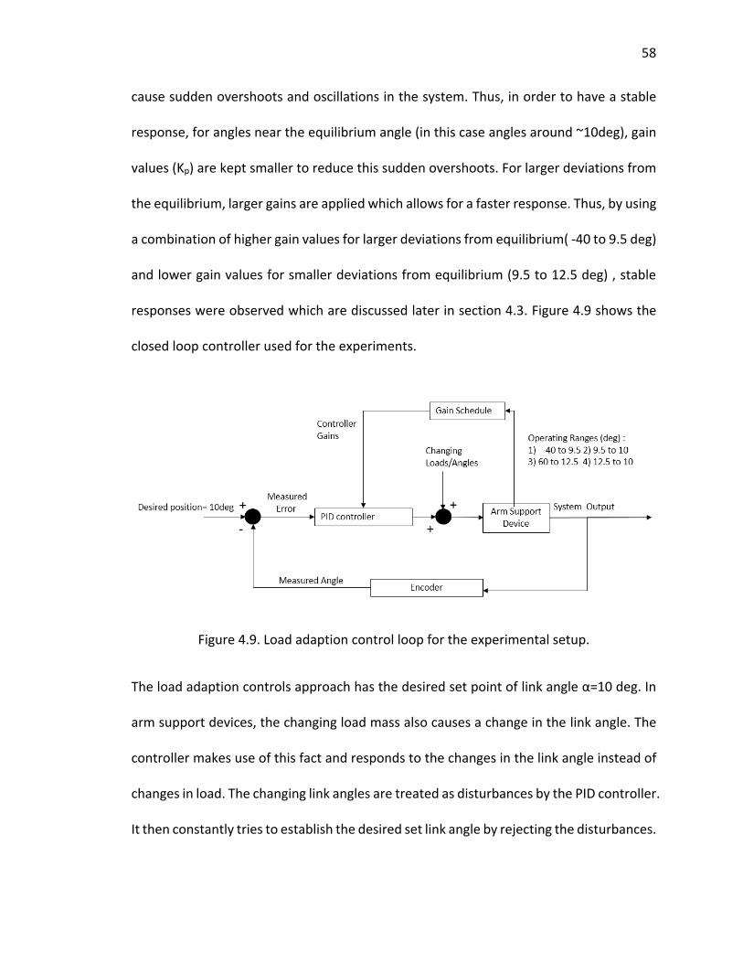
cause sudden overshoots and oscillations in the system. Thus, in order to have a stable
response, for angles near the equilibrium angle (in this case angles around ~10deg), gain
values (Kp) are kept smaller to reduce this sudden overshoots. For larger deviations from
the equilibrium, larger gains are applied which allows for a faster response. Thus, by using
a combination of higher gain values for larger deviations from equilibrium( -40 to 9.5 deg)
and lower gain values for smaller deviations from equilibrium (9.5 to 12.5 deg) , stable
responses were observed which are discussed later in section 4.3. Figure 4.9 shows the
closed loop controller used for the experiments.
Figure 4.9. Load adaption control loop for the experimental setup.
The load adaption controls approach has the desired set point of link angle α=10 deg. In
arm support devices, the changing load mass also causes a change in the link angle. The
controller makes use of this fact and responds to the changes in the link angle instead of
changes in load. The changing link angles are treated as disturbances by the PID controller.
It then constantly tries to establish the desired set link angle by rejecting the disturbances.
59
59
4.3 Load Adaption Mode Testing
To evaluate the working of the load adaption mode, the system is subjected to multiple
loads and the response recorded. Using the feedback from the encoders of the link angle
over time, the system response is observed. The load ranges selected for the experiment
are from 1.375 lbs. to 12.5 lbs. The device is in the load adaption mode and is initially at
the desired equilibrium link angle of 10 deg. The current set up has one spring with
stiffness (K=34lbs/in). The device is initially tested with lower gain values to check for the
stability of the system. In this experiment loads are changed without the human arm in
the loop. Also the initial experiment neglects damping (very low Kd ) and human arm
weight. Figure 4.10 on next page shows the response of the system without external
damping and without human arm weight estimation.

60
60
60
Figure 4.10. Response of the adaptive system with slower gains, without damping and initial arm weight.

61
61
In this case the system takes between 4 to 13 seconds to completely adapt to loads
varying from 1.375 lbs. to 12.5 lbs. The response of the system is ultimately effective in
adapting for new load mass, but slow and with significant oscillatory behavior. Different
drops in link angles are observed which are caused due to the time delay in adjusting the
angle back to the desired equilibrium position. As soon as a new load mass is added to
the arm device, it moves down to a lower position (-20 deg to -50 deg) as the mechanism
doesn’t have enough support for the new load at that moment. The controller at this
point starts adjusting for the newer load. Adjustment of the link angle is dependent on
the ‘a’ value. For larger loads the required ‘a’ value is higher which leads to higher settling
time of the system. For smaller loads (<=5lbs), oscillatory behavior is also observed which
would likely be unwanted for the user. To improve upon this, an approach with increased
damping and higher gain values was implemented.
By attaching a constant weight (3.5lbs) which replicates the weight of the human
arm, the damping in the system is increased. Also High values of Kp and Kd are used in
this case. Higher Kp values makes the response time faster and higher Kd value leads to
increased damping to smooth out the oscillations and overshoots. High values Kp and Kd
in the range of -40 to 9.5 deg (Table 4.2) ensure a fast response. Due to the immediate
responses, the lower load masses are found to deviate less from the desired equilibrium
position in the regions of -15 deg to 10 deg as shown in Figure 4.11.

62
62
62
Figure 4.11. Response of the system with damping, initial arm weight and faster gains.

63
63
This second approach has improved the adjustment settling time with a range from 2 to
7.5 second for loads (1.375lbs to 12.5lbs), as compared to the 4 to 13 second response
range before. The response observed is smoother with max over-shoot of only ~10deg.
Because of this, the controller can accommodate higher proportional gain values leading
to a faster response. The controller starts responding noticeably to lower loads (<=5 lbs)
within ~0.5 to 0.8 seconds. For higher loads the response times are between ~1-2 seconds.
Adjustment time vs loads are plotted for both the approaches in Figure 4.12 below.
Figure 4.12. Adjustment time (sec) vs load (lbs.) comparison with slower gains (no damping and arm weight) and faster gains (human arm weight and damping).
Experimental data points are shown as solid dots and linear curves are fitted.

64
64
From Figure 4.12, we can observe how the adjustment times vary with respect to
changing loads. The response times were observed to be much faster for tests with
initial arm weight and damping.
The repeatability of the system was also observed, and one example of repeated trials
with the same system settings is shown in Figure 4.13.
Figure 4.13. Repeatability of the load adaption mode.
Figure 4.13 shows 5 set of tests to measure the response of the device adjustment for
2.75 lbs load. With an average settling time of 2.9 seconds for this load and standard
deviation of 0.35 seconds; the approach is found to be highly repeatable. This indicates
that along with faster adjustment capabilities, this approach is also highly repeatable.

65
65
From the response time results, the load adaption mode can be assessed. The
current setup works well for lower ranges of load (0-7lbs) as the responses are found to
be fast enough to keep the links near the desired equilibrium position. From Figure 4.11,
the range of deviation of the links from the desired positons are within -15 to 10 deg
ranges for loads <=7lbs. However, for higher loads, there is a significant lag in response.
Link angles fall farther from the desired position for longer duration in the range of -40 to
10 deg.
It may be possible to yield better response times for a higher set of loads if stiffer
springs are used. Also, higher power actuation might be required for this. However, since
higher load requirements are more applicable in an industrial setting, this approach
would still remain cost effective and could be expected to have relatively lower power
requirements when compared to other forms of actuation [16].
4.4 Human-Centered Framework for Evaluating Load Adaption
In order to have an effective response from the system, the user should start feeling the
effect of adjustment within certain time limits. In user interface research it has been
found that too much delay in response of a system can be perceived as an interrupting
and slow response and may cause user concern regarding the device/system. In order for
a response to be effective, it should match the speed of human thought processes and
decision making. From the concepts of user-interface design methods [25], the
significance of different response times are as follows:

66
66
Response time of <1-2 seconds are preferable for tasks requiring continuity of
thinking.
Response time of 2-4 seconds are acceptable when the task does not require a high
level of concentration.
Response time of 4-15 seconds are acceptable if tasks require only minimal short
term memory to complete.
The human experience of the current moment extends over a time period up to 2 to 3
seconds, where there is continuity of thinking and no perceived delays by the user.
Though a very short time response tends to be perceived more favorably, a system
response near or less than 2 seconds may still be perceived as connected to the user
initiation of the adaption mode.
Similarly, in the work accomplished by Card et al. [24], 3 main response time limits
are found as follows:
0.1 seconds: Time limit for the user to feel an instantaneous response.
1.0 seconds: Time limit for uninterrupted thought process of the user.
10 seconds: Time limit for keeping user’s focus fully on the task.
From the study of these user interface response time limits, we can get a good idea as to
what sort of response times are desirable and acceptable. The results from the response
times with damping and initial arm weight (Figure 4.11) indicate different settling times
for different loads. For loads below 7.5lbs, the settling times are found to be in the range
of 2 to 4 seconds. This time is near the limits of the human experience of the ‘present’
67
67
moment as discussed in the user interface research [25]. In addition, the time within
which the adjustment system starts responding can also be analyzed from the response
plot. The duration during which the controller starts reacting to the change in load would
the time duration between the lowest position of the link after addition of new load and
the settling point. For lower loads (<=7.5lbs), this responses start from ~0.5 seconds (for
1.375 lbs.) to ~1 seconds for (7.5lbs). Thus the initial response times lie in the range of
less than 1 second, time limits for continuity of thought for the user. For higher loads, the
response times of the device are greater than 2 seconds. This case for higher loads (above
7.5lbs) could cause a perceived delay in the response of the system for the user.
This framework for assessing the response of the adjustment system using the
user interface design concepts gives us good insights into the evaluation of the system
response. The current approach for adaptive seems have immediate response for smaller
loads (<=7.5lbs). However, for larger loads, the user might feel a delayed response. This
is due to the fact that the adjustment value ‘a’ required to regain equilibrium is higher for
larger load. Higher stiffness springs can reduce the required ‘a’ value for larger loads.
A stiffer spring or a combination of springs could make the adjustment response
faster. With more stiffness, the adjustment value ‘a’ required would be less, making the
system more sensitive. This would lead to faster response times. More accurate
evaluation of how this adjustment mechanism would ‘feel’ to the user would require
human trials. Nonetheless, the framework proposed here for developing and evaluating
adaptive modes does give insights in what system performance one should strive for
while making design and control decisions. Such a framework is not only a good indicator

68
68
for system performance, but also avoids unnecessary human experimentation and
associated time and cost as fewer human experiments are required to evaluate basic
aspects of the system.

69
69
CHAPTER 5. POSITION ADAPTION MODE
As users of a gravity-balancing arm device move through different angular positions in the
passive mode, the support provided by the arm device becomes limited at higher link
positions. For some users this can be a source of fatigue and exhaustion. Hence there is a
need for a mode which can continuously provide support throughout the range of motion
and establish static balancing at any link position. In this chapter, development of such
position adaption mode is discussed and its response is also tested for different loads.
For different values of ‘a’ the spring can provide support to different loads at the
horizontal equilibrium position (0 deg). However, as we move to higher angular positions,
the support force provided by the spring keeps on reducing. In order to provide constant
support throughout the range of motion, the ‘a’ value needs to be adjusted for each
changing angle. The changing ‘a’ values tries to keep the spring extension constant for
different angles, thus leading to support throughout. Based on this concept, the Position
adaption mode is developed.
5.1 Position Adaption Controller
Spring Adjustment parameter ‘a’ values determination for different link angles:
In Equation (4.11), static balancing is obtained by substituting ∅̇ = 0 and∅̈ = 0.

70
70
𝑀𝑔 = 𝐾𝑎 (1 −ℎ0
ℎ) (5.1)
The equation used to find the length of the spring is
ℎ = √(𝑎2 + 𝐿2 − 2𝑎𝐿 ∗ 𝑠𝑖𝑛(𝛼) (5.2)
From the static equilibrium condition & Equation (5.2), the ‘𝑎’ value can be found out for
a given link angle. In order to provide constant support throughout the range of motion,
the length of the spring should remain constant. From the load adaption mode, the value
of ℎ can be calculated for a given static equilibrium angle and a given mass. Then by re-
arranging Equation (5.2), the value of ‘𝑎’ can be found for any changing angle as shown
in Equation (5.3).
𝑎 = √ℎ2 − 𝐿2 + 2𝑎𝐿 ∗ sin(𝛼) , (5.3)
From Equation (5.3), the ‘𝑎’ value can be updated for any changing link angle and constant
ℎ for a given load mass. This forms the basis for the controls approach for position
adaption mode.
Controller implementation: The control loop is developed based on the adjustment ‘a’
value determination.

71
71
Figure 5.1. Control loop for position adaption mode.
In Figure 5.1, the control loop for the position adaption mode is shown. As discussed
before, the desired ‘a’ value is obtained from the changing angles using Equation (5.3). So
the task for the controller is to reach the desired ‘a’ value. Using PID controller and the
feedback from the motor encoder, the arm support device is adjusted to provide static
balancing to a load at any link position. It can also provide constant support throughout
the range of motion when link positions are continuously changed. The gain values were
obtained from trial and error experimentation.
5.2 Results
The position adaption mode is tested by experimenting with different load ranges (0 to
15.5lbs). The user moves the arm devices with a given load to any desired angular position.
As soon as the link angles start changing, using the feedback from the link angle encoder,
the desired ‘a’ value gets updated. This desired ‘a’ value is the value required to keep
static balancing of the load at the given position. Now using the motor’s encoder this

72
72
variation of the desired ‘a’ values are experimentally observed for the load ranges. Figure
5.2 shows how experimentally measured desired ‘a’ values vary with changing angles.
Figure 5.2. Experimentally measured desired ‘a’ value for statically balancing the given load at varying link angular positions.
It should be noted that from this result in Figure 5.2, at any angular position the
corresponding ‘a’ value can be obtained. This can be used to find the spring force
(Equation (5.1)) for statically supporting the given load at that angular position. From
Figure 5.2, it can be also be observed that for the loads <=5.5 lbs, the adjustment in ‘a’
Experimental data points are shown as solid dots and 2nd degree polynomial curves are fitted.

73
73
value required per link angle is lesser than for higher loads (>5.5lbs) in order to maintain
constant support. This would mean that the system responds faster for lower loads when
compared to higher loads. An analysis of the measured linkage angular velocity with
respect to load masses also gives similar insights.
Figure 5.3. Measured angular velocity of the links vs load mass.
Figure 5.3 shows how the angular velocity (omega) of the links change with respect to
loads. For lower loads (<6lbs), angular velocity of links are found to be higher. Angular
velocities of ~15 deg/s on average are observed during this range. This means the user
Experimental data points are shown as solid dots and a linear curve is fitted.

74
74
can move through 15 deg of constantly supported change within one second. Besides
quick response, the user operating force in dynamic mode is very low. For any angular
change of 0.5 deg or greater, the controller automatically adjusts the load support for the
new position. Thus, the introduction of position adaption mode leads to support for a
load at any desired link position.

75
75
CHAPTER 6. CONCLUSIONS
In order to expand and increase the use of arm support devices, it is necessary to
improve the existing devices to overcome existing challenges faced by users. Till now, only
a limited number of devices have incorporated adjustment capabilities for changing
conditions like changing loads and positions. Energy free adjustment methods and user
controlled assist systems have enabled interaction with changing support requirements.
However, these methods either require fatiguing manual efforts or require user to make
constant decisions. Hence, a need for adaptive system was felt for this class of arm
support devices.
This thesis presented a design of adaptive system which can be implemented in the
existing class of arm support devices. From development of the adaptive arm device
prototype to implementation and testing of the controls approach, this thesis gives
insights on the developmental as well as the assessment aspects of such a system.
Through incorporation of feedback control, 2 adaptive modes were developed: load
adaption mode and the position adaption mode. Actuation designs were initially finalized
based on various designs and drive system analysis. To accomplish closed loop control,
feedback from encoders on the links and motor encoders were used. Desired equilibrium
positions were then analyzed by studying the system dynamics.
76
76
An approach for controlling such a spring based system was also shown using gain
scheduling in a PID controller. Besides discussing the techniques for implementing such a
controller, an assessment frame work was also developed which evaluates the response
of the adaptive system. For lower loads (<=7lbs), the time by which the system begins
responding have been found to be around 0.5 seconds , which is very nearly a response
that the user feels to be natural and instantaneous. For higher loads, the system begins
responding after a lag of around 0.8-1 seconds, which is not perceived as instantaneous
and the user might feel some delayed response from the device. This limitation for larger
loads arises because of the spring stiffness that was used for the present prototype. For
future experiments, a higher stiffness spring can be used which can not only support
larger ranges of load but also makes the system more sensitive and improves the
response of the proposed adaptive. Also, the settling response times were found to be in
the range of ~2 to 7 seconds. Although, faster settling response times are possible to
achieve, this would have a trade off with the power requirements, weight and cost of the
system. While an ideal response would be instantaneous, this would lead to high power,
weight and associated cost requirements. Thus currently, a reliable adaptive arm system
requires a tradeoff between achievement of faster response times and developing a low
power, lightweight and low cost design.
In addition to the load adaption mode, a need for a position adaption mode was
also identified. By constantly adjusting the ‘a’ value for different link angles, a given load
can be statically balanced for any desired link position by using PID controller. The use of
this mode is intuitive and requires minimal effort. The response speeds of the device in

77
77
this mode were analyzed and were found to be faster for lower loads (<=5lbs). Again with
higher loads, the response speeds were lower, suggesting the potential use of higher
stiffness springs for a better response.
The incorporation of these two adaptive modes have improved the overall
interaction of passive-based arm support devices. This improvement can be better
understood by the conceptual diagram of existing devices as shown in Figure 6.1.
Figure 6.1. Comparison between arm systems based on adjustment type and user interaction. The placement of existing devices on this figure is based on the author’s qualitative assessment of each device. Here, “manual adjustment” is used to mean that the user physically interacts to either directly adjust the mechanism or via a controller joystick or setting knob. In either case, this manual adjustment requires prolonged interaction and user decision making about the adjustment of the device.
Figure 6.1 shows a comparison between various arm systems on the basis of the
adjustment capabilities and user interaction with the device. Existing products like WREX,

78
78
equipoise and SAEBO arm have manual adjustment capabilities where the user makes
adjustments by changing knobs or rotating cranks in order to support newer loads or
positions. Devices like TOP-help, ArmOn , GoWing Arm Support and Dynamic Arm Support
(DAS) have manual adjustment capabilities which are power assisted by an actuator. In
these devices, the user either operates a switch or a joystick continuously to adjust the
device to the changed position or load. The proposed Adaptive Gravity Balancing Arm
System builds upon the positive qualities of passive gravity balancing arm systems, but
with an added adaptive control system it lies in the adaptive adjustment region. By using
a feedback loop controller and an intermittently active actuator, the device automatically
adjusts to any changing loads and position without the need for long user involvements
(it requires user initiation of the adaption process but not user control throughout).
In addition to the introduction of the adaptive modes, the proposed device also
has low power and a high range of load support. The adaptive approach is intermittently
active which means it also tends to be energy efficient. Both adaptive modes on average
use approximately 48W of power (2amps at 24VDC). A powered wheel chair battery can
easily incorporate such an arm device system. Typical power wheel chair batteries can
store approximately 800 Whrs. So at 48W, the device could operate continuously for 15
hours, though this system only requires intermittent operation and so the duration would
be significantly longer in practice. Thus despite having automatic adjustment, this system
remains energy efficient.

79
LIST OF REFERENCES

79
79
LIST OF REFERENCES
[1] A. Van Drunen. Balancing = Beautiful, Master’s Thesis .TU Delft, Netherlands (2008).
[2] T. Rahman, W. Sample, R. Seliktar, M. Alexander, M. Scavina. A Body-Powered Functional Upper Limb Orthosis. Journal of Rehabilitation Research and development, vol. 37, no. 6, 2000
[3] T. Haumont, T. Rahman, W. Sample, M. King, C. Church, J. Henley, S. Jayakumar. Wilmington robotic exoskeleton: A novel device to maintain arm improvement in muscular disease. Journal of Pediatric Orthopedics, e44-9, Jul-Aug; 31(5): 2011
[4] Focal meditech, TOP-Help: http://www.focalmeditech.nl/eng/en/home/home/38-top.html
[5] Zero G: http://www.equipoisinc.com/products/zerog4/
[6] Steadicam: http://tiffen.com/steadicam
[7] SEABO MAS: http://www.saebo.com/products/saebomas/
[8] J.L. Herder, R.Barents, B.M. Wisse, V. Dorsser. Efficiently variable zero stiffness mechanisms. Workshop on Human Friendly Robotics, University of Twente, 2011
[9] V. Dorsser, R. Barents, B.M. Wisse, J.L Herder. Gravity-Balanced Arm Support with Energy-Free Adjustment. ASME Journal of Medical Devices, Vol. 1, No. 2, pp. 151-158. 2007
[10] R. Barents, M. Schenk, V. Dorsser, B.M. Wisse, J.L. Herder. Energy-free adjustment by spring-to-spring balancing in gravity equilibrators. ASME Journal of Mechanical Design, 133(6)061010. 2011

80
91
[11] B.M. Wisse, W.D. van Dorsser, R. Barents, J.L. Herder. Energy-Free Adjustment of Gravity Equilibrators Using the Virtual Spring Concept. ICORR2007, Noordwijk, The Netherlands. 2007
[12] J.L .Herder, N. Vrijlandt, T. Antonides, M. Cloosterman, P. Mastenbroek. Principle and design of a mobile arm support for people with muscular weakness. Journal of Rehabilitation Research and Development, Volume 43 Number 5, pp- 591-604, 2006
[13] Gowing Dynamic Arm Support: http://www.innovationshealth.com/gowing/
[14] Exact Dynamics (DAS): http://www.exactdynamics.nl/site/?page=das
[15] Exact Dynamics B.V. Arm support, and sitting support with such arm support. US Patent 20090121111 A1. 2009
[16] B. van Ninhuijs, L.A. van der Heide, J.W. Jansen, B.L.J. Gysen, D.J. van der Pijl and E.A. Lomonova. Overview of Actuated Arm Support Systems and Their Applications. Actuators 2, 86-110; doi: 10, 2013
[17] J. Ackerman, J. Seipel. Design of Stabilizing Arm Mechanisms for Carrying and Positioning Loads. Journal of Mechanical Design 137(10), 104501. 2015
[18] D. Findeisen. System Dynamics and Mechanical Vibration, Berlin, Heidelberg: Springer Berlin Heidelberg, 2000.
[19] Century Spring: http://www.centuryspring.com/Store/item_detail.php?StockNumber=81049
[20] J.J. Uicker, Jr., G.R. Pennock, and J.E. Shigley. Theory of Machines and Mechanisms, Fourth Edition, New York : Oxford University Press, 2011
[21] Ball Bearings: http://www.mcmaster.com/#57155k304/=zy443v
[22] Lead screw and lead nut: http://www.nookindustries.com/Product/ProductName/101740

81
91
[23] Torque Calculation, Lead screw: http://www.sdp-si.com/D810/PDFS/Ball%20And%20Acme%20Lead%20Screw%20Technical%20Info.pdf
[24] W.O. Galitz. The Essential Guide to User Interface Design: An Introduction to GUI Design
[25] R.B. Miller. Response time in man-computer conversational transactions. Proc. AFIPS Fall Joint Computer Conference Vol. 33, 267-277. 19