Adaptive Control for ESTOL Design Abstractions ... (Acosta).pdf · The tool simulates a generic...
22
* Research Engineer, Intelligent Systems Division, NASA Ames Research Center M/S 269-1, AIAA Member † Research Scientist, Intelligent Systems Division, NASA Ames Research Center M/S 269-1, AIAA Associate Fellow ‡ Computer Engineer, Intelligent Systems Division, NASA Ames Research Center M/S 269-1, AIAA Member Adaptive Control for ESTOL Design Abstractions— Performance Analysis Diana M. Acosta * , K. KrishnaKumar † , and John T. Kaneshige ‡ NASA Ames Research Center, Moffett Field, California, 94035 Aviation operations in the United States are expected to increase multifold by 2025. The consequences of such an increase in air traffic could become overwhelming at major airports. Extreme Short Take Off and Landing (ESTOL) aircraft offer the ability to alleviate the foreseen congestion at major airports by utilizing small runways that are inaccessible to conventional airplanes. In this paper, we address the challenges associated with ESTOL flight in the midst of modeling uncertainties and flight dynamics variations. As a preliminary investigation, we implement and test a direct-adaptive flight control architecture previously developed at NASA Ames Research Center. The controller includes direct adaptation to compensate for large errors without identifying the source. This ability is particularly appropriate for controlling vehicles subject to a variety of damages, failures and other dynamic changes or uncertainties. Preliminary results show that the direct-adaptive flight controller is successful in accommodating various ESTOL design abstractions. Control performance as it adapts to the “unmodeled” dynamics is documented for various flight conditions. Nomenclature " = Angle of attack, alpha A = Matrix in linear equations of motion " = Direct adaptation basis function B = Matrix in linear equations of motion C = Generic aerodynamic coefficient v C = Direct adaptation input vector C CC = Generic aerodynamic coefficient term for circulation control C BF = Generic aerodynamic coefficient term for blown flaps C GT = Generic aerodynamic coefficient of the generic transport airplane C L = Aerodynamic lift coefficient C μ = Thrust coefficient C μ = Normalized thrust coefficient C μ max = Maximum thrust coefficient D = Aerodynamic drag force " = Scalar, active circulation control input variable " = Direct adaptation learning rate L = Aerodynamic lift force μ = Direct adaptation dead band term Q = Dynamic pressure Q min = Minimum dynamic pressure
Transcript of Adaptive Control for ESTOL Design Abstractions ... (Acosta).pdf · The tool simulates a generic...
* Research Engineer, Intelligent Systems Division, NASA Ames Research Center M/S 269-1, AIAA Member † Research Scientist, Intelligent Systems Division, NASA Ames Research Center M/S 269-1, AIAA Associate Fellow ‡ Computer Engineer, Intelligent Systems Division, NASA Ames Research Center M/S 269-1, AIAA Member
Adaptive Control for ESTOL Design Abstractions—Performance Analysis
Diana M. Acosta*, K. KrishnaKumar†, and John T. Kaneshige‡ NASA Ames Research Center, Moffett Field, California, 94035
Aviation operations in the United States are expected to increase multifold by 2025. The consequences of such an increase in air traffic could become overwhelming at major airports. Extreme Short Take Off and Landing (ESTOL) aircraft offer the ability to alleviate the foreseen congestion at major airports by utilizing small runways that are inaccessible to conventional airplanes. In this paper, we address the challenges associated with ESTOL flight in the midst of modeling uncertainties and flight dynamics variations. As a preliminary investigation, we implement and test a direct-adaptive flight control architecture previously developed at NASA Ames Research Center. The controller includes direct adaptation to compensate for large errors without identifying the source. This ability is particularly appropriate for controlling vehicles subject to a variety of damages, failures and other dynamic changes or uncertainties. Preliminary results show that the direct-adaptive flight controller is successful in accommodating various ESTOL design abstractions. Control performance as it adapts to the “unmodeled” dynamics is documented for various flight conditions.
Nomenclature
!
" = Angle of attack, alpha
!
A = Matrix in linear equations of motion
!
" = Direct adaptation basis function
!
B = Matrix in linear equations of motion
!
C = Generic aerodynamic coefficient
!
v C = Direct adaptation input vector
!
CCC
= Generic aerodynamic coefficient term for circulation control
!
CBF
= Generic aerodynamic coefficient term for blown flaps
!
CGT
= Generic aerodynamic coefficient of the generic transport airplane
!
CL
= Aerodynamic lift coefficient
!
Cµ = Thrust coefficient
!
C µ = Normalized thrust coefficient
!
Cµmax = Maximum thrust coefficient
!
D = Aerodynamic drag force
!
" = Scalar, active circulation control input variable
!
" = Direct adaptation learning rate
!
L = Aerodynamic lift force
!
µ = Direct adaptation dead band term
!
Q = Dynamic pressure
!
Qmin
= Minimum dynamic pressure
!
S = Reference area
!
T = Thrust magnitude
!
Tmax
= Maximum thrust magnitude
!
v u = Control input
!
v u
cmd = Commanded control input
!
W = Neural network weight matrix
!
˙ W = Change in neural network weights
!
v x = Body-fixed angular velocities, state variables vector
!
v ˙ x = Body-fixed angular accelerations
!
v ˙ x
cmd = Commanded body-fixed angular accelerations
!
v ˙ x
DA = Body-fixed angular accelerations from direct adaptive compensation
!
v x
des = Desired body-fixed angular velocities
!
v ˙ x
des = Desired body-fixed angular accelerations from feed forward compensation
!
v ˙ x
PID or
!
v ˙ x
PI = Body-fixed angular accelerations from feedback compensation
I. Introduction Aviation operations in the United States are expected to increase multifold by 2025.1 With this large
increase in air traffic, the noise, pollution and congestion at major airports are also expected to raise.1 Solutions to alleviate these problems will require advances in many disciplines of aeronautics, and airspace and airport operations. NASA Aeronautics has initiated research efforts towards creating a body of knowledge that will lay the foundation to address the challenges associated with Next Generation (NextGen) airspace system. One area of focus under these efforts is in the research of NextGen aircraft design concepts that will have reduced noise and emissions footprint, and increased aircraft performance, measured through a reduction in specific fuel consumption and/or field length.1 Extreme short take off and landing (ESTOL) designs are one such example currently being studied. ESTOL aircraft are designed for efficient cruise and short take off and landing capability. This conceptual transport configuration offers the ability to reduce congestion in the terminal area through approaches and landings that do not interfere with traditional air traffic. The extended ESTOL flight envelope enables utilization of small runways at large and small airports. The traffic pattern specific to ESTOL aircraft would also include a slow steep decent to the runway, which lowers community noise by reducing the noise footprint.2
While the ESTOL capability is beginning to show benefits to the civilian transport industry, short take off and landing (STOL) emerged as an operational requirement for military transport aircraft in the late 1960’s.3 Despite the legacy of research and development, knowledge of ESTOL aerodynamics, interactions between propulsive and aerodynamic forces, and structural issues for potential ESTOL design abstractions are all still poorly understood. Research of STOL and high-lift technologies can be leveraged for ESTOL application, but many aspects of ESTOL objectives remain a challenge, including stable and performance-seeking guidance and control. Some of the control challenges for ESTOL flight include: (1) Dynamic characteristics of the aircraft change drastically during the flight regime between the high speeds for cruise and decent and the slow speeds required for ESTOL; and (2) ESTOL flight dynamic models for various ESTOL design options are poorly understood and must be assumed to have uncertainty beyond what robust control alone can achieve.
To address the challenges stated above, we examine the benefits of a direct-adaptive control architecture that is capable of adapting to the uncertainties and changes in the ESTOL flight dynamics. Direct-adaptive control architectures have been shown by NASA Ames4-6 and many other researchers7,8 to be appropriate for controlling flight vehicles subject to a variety of damages, failures, and other dynamic changes or uncertainties. In this study, dynamic inversion based direct-adaptive control architecture is implemented and tested using an ESTOL simulation capability that was specifically developed for the study. The simulation is capable of emulating many different ESTOL design abstractions. Our study examines the ESTOL vehicle performance for various flight conditions and ESTOL design variations. Results are documented to show the benefits of a direct-adaptive control as an option for ESTOL guidance and control.
II. Research Aircraft Simulation Modeling Tool The Research Aircraft Simulation Modeling Tool serves as a research and evaluation tool for intelligent
flight control research. The tool simulates a generic transport subsonic fixed-wing airplane capable of demonstrating a variety of ESTOL design abstractions.
The conventional airplane base model is the Advanced Concepts Flight Simulator (ACFS) airplane model of a Lockheed Georgia Company Commercial transport concept.9 The original concept aircraft is a mid-size transport with dimensions similar to that of a Boeing 757. The airframe has a wide body, low wings, T-tail, and two turbofan engines located under the wings.
The design abstractions represent ESTOL or STOL technology found in literature.3,10-18 Presently, there are five different ESTOL technologies modeled in the Research Aircraft Simulation Modeling Tool. The modeling tool provides the capability to employ each ESTOL technology individually, or simultaneously with other ESTOL technologies. This allows a variety of different vehicles to be studied on the single research platform. The dynamic effects of the ESTOL technologies can also be scaled to be more or less prominent in order to simulate variations in control power and control coupling.
The versatility of the Research Aircraft Simulation Modeling Tool to simulate a variety of ESTOL design abstractions provides the ability to evaluate intelligent flight control techniques with respect to the various ESTOL design variations, and analyze the controllers’ ability to meet flight control metrics and performance goals of NextGen.
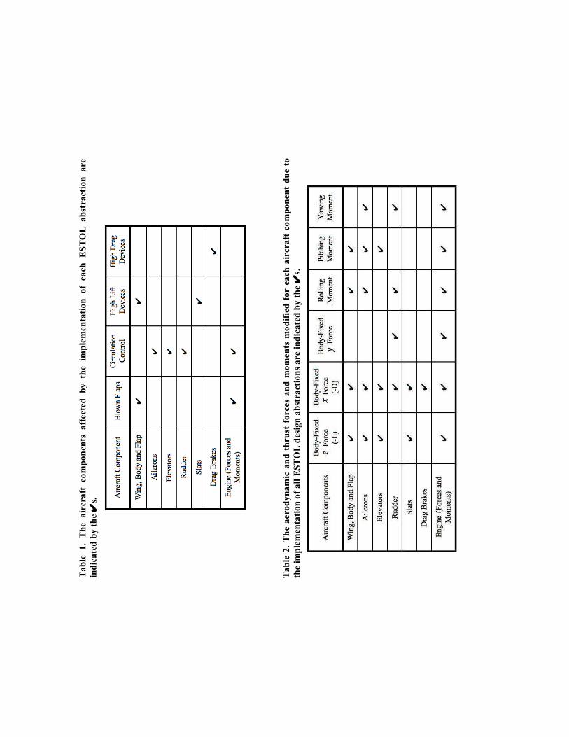
The ESTOL technologies that allow for the various ESTOL design abstractions include blown flaps, active and passive circulation control, high lift devices, and high drag devices. The dynamic effects of these technologies were modeled on the conventional airplane model; the implementation is described in this section and a table indicating the aircraft components affected by the implementation of each abstraction is given in Table 1. Since the effects of these technologies are primarily correlated with the aerodynamic and propulsive nature of the aircraft, modifications are applied to the aerodynamic coefficients and thrust vectors; no structural or inertial changes are considered. An overview of the aerodynamic and thrust forces and moments modified for each aircraft component due to the implementation of all the ESTOL design abstractions is given in Table 2.
A. Blown Flaps The ESTOL technology referred to as blown flaps represents the case where the engines are mounted
above or under the wing such that the engine exhaust encounters the surface of the extended flaps. This configuration provides powered lift by assisting the flow over the wing and flap to remain attached, effectively elongating the lifting surface and vectoring the thrust of the engine downwards.
The two physical effects are modeled by modifying the aerodynamic coefficients and thrust vectors, respectively. The first physical effect, that of extending the attached airflow over the wing and flaps, is modeled through an augmentation to the lift, drag and pitching moment coefficients. In the case of an engine failure, the roll coefficient is also augmented since the powered lift effect would be asymmetric. This augmentation is in the form of a term added to the conventional aerodynamic coefficient. The added term for the blown flaps,
!
CBF
, is a nonlinear function of the conventional coefficient of the generic transport model,
!
CGT
, angle of attack,
!
" , and normalized thrust coefficient,
!
C µ . Equation 1 provides this relationship for a general aerodynamic coefficient,
!
C .
!
C = CGT
+ CBF
CGT,",C µ( ) (1)
The normalized thrust coefficient,
!
C µ , is considered to be the ratio of the thrust coefficient,
!
Cµ , to the maximum thrust coefficient,
!
Cµmax , where the thrust coefficient is equal to the engine thrust divided by the dynamic pressure,
!
Q , and reference area,
!
S .
!
C µ =Cµ
Cµmax
(2)
!
Cµ =T
Q " S,
!
Cµmax =Tmax
Qmin" S
(3)
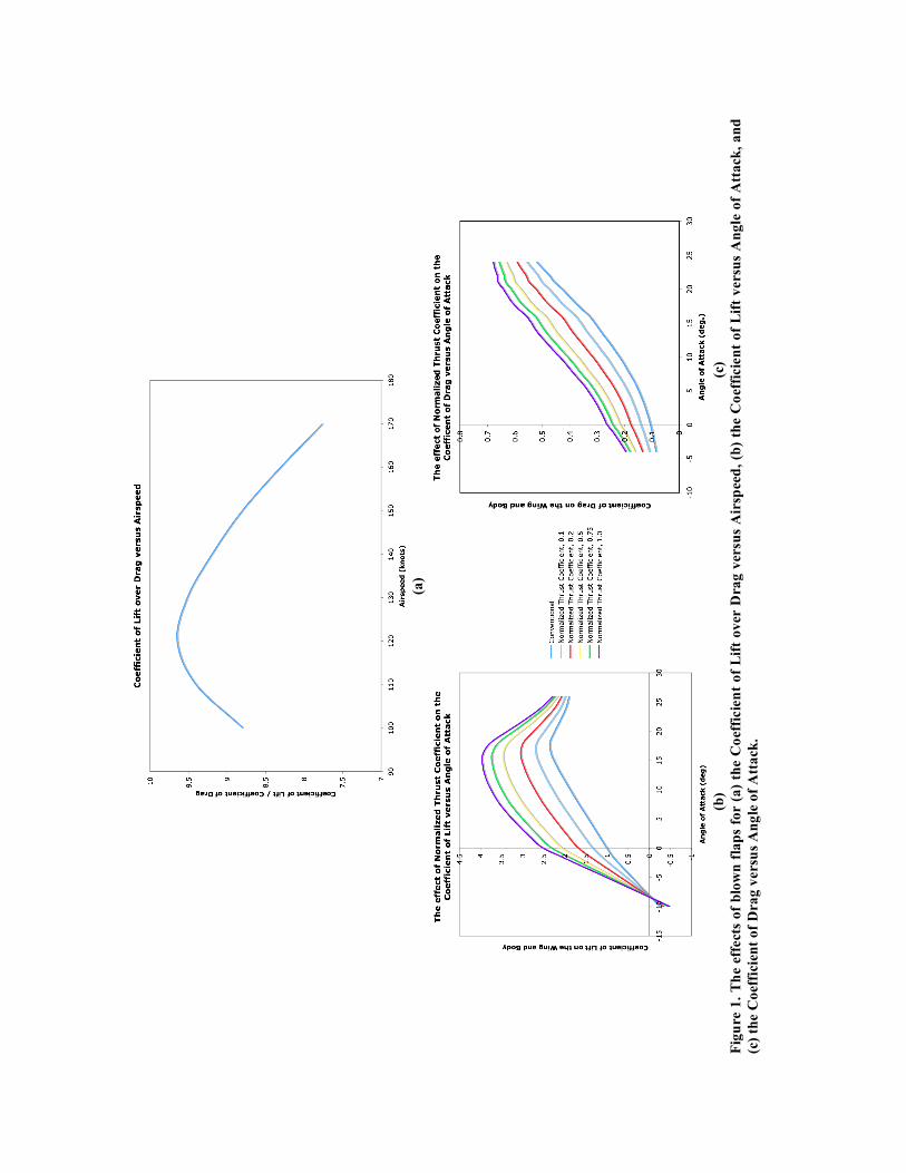
For all normalized thrust coefficients the
!
L D as a function of airspeed remains the same, even though the individual values of lift and drag shift, as shown in Fig. 1.
The second physical effect associated with externally blown flaps is thrust vectoring and is modeled by scaling the magnitude of the engine forces and moments as a function of the flap deflection.
A. Circulation Control Circulation control, known by a variety of different names (i.e. boundary layer control, active flow
control), is a technology aimed at improving the lift characteristics over surfaces and actuators. While circulation control can be achieved through number of different methods, the method modeled is comprised of high-pressure engine bleed ducted to nozzles over the control surfaces.
Similarly to the aerodynamic modeling of the blown flaps, the circulation control effects are modeled as added terms to the conventional aerodynamic coefficients. For circulation control, the added term,
!
CCC
, is a nonlinear function of the conventional coefficient of the generic transport model and normalized thrust coefficient.
!
C = CGT
+ CCC
CGT,C µ( ) (4)
The circulation control modeling completed for this research tool is very flexible. The circulation control technology is modeled in a manner that allows the flow to be actively or passively controlled. Passive circulation control represents the case when the normalized thrust coefficient in Eq. 4 is a function of the engine state. Here, Eq. 2 defines the normalized thrust coefficient
!
C µ and Eq. 3 defines the thrust coefficient
!
Cµ , just as was done for the blown flaps calculation. If active circulation control is chosen, the pilot is able to specify the magnitude of the normalized thrust coefficient through a scalar
!
". Here, Eq. 2 still defines the normalized thrust coefficient
!
C µ , but Eq. 5 defines the thrust coefficient
!
Cµ . The scalar
!
" can range from zero to one, with zero specifying a control input for no circulation control, or no bleed air ducted to the control surfaces, and with one representing full or maximum bleed air.
!
Cµ =" #T
max
Q # S (5)
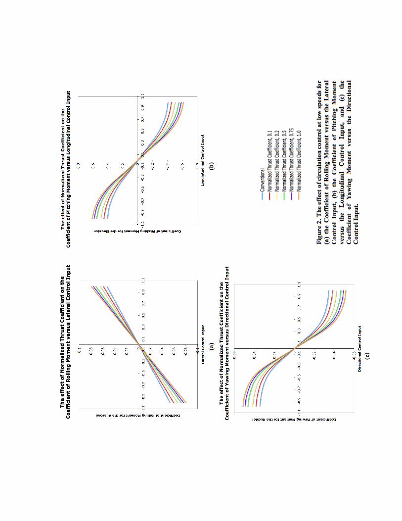
The circulation control is also modeled with the option of enhancing the flow over control surfaces located on the entire aircraft or on just the wings. When circulation control is considered for the entire aircraft, engine bleed is ducted to the ailerons, elevators and rudder. When circulation control is considered for the wings, engine bleed is only ducted to the ailerons. The aerodynamic lift, drag and side forces and roll, pitch and yaw moments are modified accordingly. The effects on the rolling, pitching and yawing moment coefficients as a function of lateral control input, longitudinal control input, and directional control input, respectively, are shown in Fig. 2 for various normalized thrust coefficients.
Due to the design of the circulation control technology, the aircraft’s aerodynamic and engine dynamics are coupled. For this model, we assume the air distribution ducts from the engines are joined such that an engine failure results in a decrease in the effective bleed pressure (represented by the normalized thrust coefficient), but no significant rolling moment is produced by asymmetric blowing over the ailerons. Also, since the high-pressure air bleed from the engines would reduce engine performance, the magnitudes of the engine forces and moments are scaled down slightly as a function of the thrust coefficient.
B. High Lift Devices The effects of high lift devices represent an increased lift capability of the wing due to more effective
flap and slat actuators. These more effective high lift actuators are modeled as a slight increase in the lift coefficient during flight, a shift in the stall condition to a larger angle of attack and an increase in maximum
lift coefficient, as shown in Fig. 3. The drag coefficient is also increased proportional to the change in lift to account for induced drag.
C. High Drag Devices High drag devices are drag brakes considered to be similar to spoilers in the fact that the high drag
panels can be deflected during flight to disrupt the airflow around the aircraft and cause an increase in drag, but the drag brakes are assumed to not affect the lift. These high drag devices, or drag brakes, are modeled by an additional drag term obtained from the spoiler aerodynamic table according to the drag brake panel deflection.
D. Stability Analysis of an Aircraft with the ESTOL Design Abstractions An evaluation of the Research Aircraft Simulation Modeling Tool is presented here which investigates
the effect of the ESTOL design abstractions on the aircraft longitudinal and lateral stability. The study compares the longitudinal and lateral modes of two aircraft configurations: the conventional configuration and one ESTOL configuration. The conventional configuration represents the generic transport airplane, with no ESTOL technology. The ESTOL configuration represents the generic transport airplane with blown flaps, active circulation control, high lift devices, and high drag devices. (The normalized thrust coefficient for the active circulation control was equal to one for the analysis, designating full or maximum bleed air.)
To conduct the analysis, linear models of the chosen aircraft configurations are extracted using the small perturbation method, and pole-zero diagrams of the linear models were plotted. Figure 4 provides the pole-zero diagrams of the models at 105 knots with the flaps and landing gear deployed. Figure 5 provides the pole-zero diagrams of the models at 300 knots with the flaps and landing gear retracted. The longitudinal and lateral modes are identified on the figures and the arrows indicate the relative root shift from the conventional transport configuration to the ESTOL configuration.
The relative root shifts from the conventional transport configuration to the ESTOL configuration are most prominent for the 105 knots flight condition. In the 105 knots flight condition, with the flaps and landing gear deployed, the effects of ESTOL is distinguished more due to the relationships between the ESTOL technologies and the dynamic pressure and flap deflection. (As discussed above, the dynamic effects of the blown flaps and circulation control are inversely proportional to the dynamic pressure, and the dynamic effects of the blown flaps are directly related to the deflection of the flaps.) For the 300 knots flight condition, with the flaps and landing gear retracted, the relative root shifts from the conventional transport configuration to the ESTOL configuration are more modest to account for the diminished effect of the ESTOL technologies at higher airspeed and in a clean configuration.
With the exception of the Dutch Roll Mode roots, all roots shift towards the left, and all complex roots shift towards the real axes as well. This represents an increase in stability and an increase in damping. The Short-Period Mode shifts due to in increase in the change in lift with alpha, which is influenced primarily by the blown flaps. The Phugoid Mode shifts due to a decrease in the lift to drag ratio for the ESTOL configuration. While both the lift and drag are increased by the ESTOL technologies, the increase in drag is larger. The Roll Mode shifts due to an increase in the roll damping, and the Spiral Mode shifts slightly to the left because of a decrease in the rolling moment due to yaw. The Dutch Role Mode roots shifts slightly to the right and away from the real axis due to a decrease in yaw damping despite a corresponding increase in side slip damping.
III. Adaptive Flight Controller Researchers at National Aeronautics and Space Administration (NASA) Ames Research Center and
NASA Dryden Flight Research Center developed the Intelligent Flight Control System (IFCS) to increase safety and maintain stability in the event of damage to the aircraft or failure of the aircraft control surfaces.4,7 The direct-adaptive control architecture of the IFCS has been shown to adapt to maintain adequate tracking errors and minimize cross-coupling effects due to airframe damage and aerodynamic actuator failure.4-7
Linear Dynamic Inversion Control is the foundation for the IFCS control law. The controller is designed such that the dynamics of the control variables are built into the controller to cancel out the vehicle dynamics, therefore globally linearizing the system such that the vehicle response matches the desired response.19 Since the vehicle dynamics can be directly incorporated into the flight controller, the need for gain scheduling is avoided.19
The linear dynamic inversion control law begins with the equation of motion for controlled system represented by the form
!
v ˙ x = A
v x + B
v u , (6)
where
!
v x is the state variables vector,
!
v u is the control input vector, and
!
A and
!
B are the dynamic parameters in matrix form. An overdot represents a scalar derivative with respect to time such that
!
v ˙ x is the
time-rate of change vector of the state variables. The control problem is to generate a commanded control input
!
v u
cmd such that the system response
!
v ˙ x matches the commanded response
!
v ˙ x
cmd. The dynamic
inversion control solution, applied to the linear equation of motion in Eq. 1, is the control input
!
v u
cmd= B
"1 v ˙ x cmd
" Av x ( ) . (7)
If the
!
A and
!
B matrices of the linear equations of motion represented the real system perfectly, the system response would equal the commanded response.
!
v ˙ x = Av x + B
v u
cmd= A
v x + B B
"1 v ˙ x cmd
" Av x ( )( ) =
v ˙ x cmd
(8)
Flight dynamics, however, are nonlinear by nature and the linear dynamic modeling must be assumed to have uncertainty. For this reason, the commanded response is a summation of the desired feed forward response and feedback compensation, as seen in Eq. 9.
!
v ˙ x
cmd=
v ˙ x
des+
v ˙ x
PID (9)
The desired feed forward response,
!
v ˙ x
des, is the pilot input passed through a filter (often considered to be a
reference model) that shapes the pilot inputs in order to achieve good handing qualities. The compensation used in the feedback loop varies. Typically a type of proportional-integral-derivative (PID) control law is applied, hence the label
!
v ˙ x
PID. The accuracy of the dynamic inversion controller is, therefore, improved
because the errors caused by uncertainties in the system dynamics and disturbances are reduced through the feedback control loop.
The IFCS research has enhanced this general dynamic inversion control law by incorporating direct adaptation.4-7 The adaptation can explicitly addresses uncertainty in aircraft dynamics and changes to the system due to damage or failure, and has been shown to reduce the tracking error and increase the robustness of the control law.
The direct adaptive control law augments the feedback compensation. The commanded system response is therefore equal to the summation of the desired feed forward response, feedback proportional-integral compensation and direct adaptation compensation, as seen in Eq. 10.
!
v ˙ x
cmd=
v ˙ x
des+
v ˙ x
PI"
v ˙ x
DA (10)
The direct adaptation is achieved with sigma-pi neural networks. The neural networks adapt to the current system in order to correct for large errors not expected during the control design. The control augmentation control signal,
!
v ˙ x
DA, produced by the neural networks is represented by Eq. 11, where
!
W is the network weight matrix,
!
" is the basis function, and
!
v C is an input vector. The network weights adapt
according to Eq. 12, where
!
" is the learning rate and
!
µ is a dead band term. Control inputs, sensor feedback, and bias terms are selected for the input vector to capture multiple modes of aircraft dynamics. This allows the neural networks to provide coupled control signals in response to coupled aircraft dynamics.
!
v ˙ x
DA= W
T"v C ( ) (11)
!
˙ W = "#v ˙ x
PI$ + µ
v ˙ x
PIW( ) (12)
Since the neural networks adapt directly, the neural networks compensate for the errors without identifying the source. This allows the controller to successfully control vehicles subject to a variety of damages, failures or other dynamic changes, including those which produce cross coupling characteristics typically ignored during modeling.
Figure 6 shows the control diagram for the direct-adaptive control architecture. The purpose of this paper is to evaluate the ability of the direct-adaptive control architecture to control
ESTOL aircraft without awareness of the dynamic characteristics related to the vehicle’s ESTOL technology. In this control study, no pilot inputs are considered. Instead, longitudinal maneuvers are commanded by an autopilot that generates the body-fixed velocities,
!
xdes
, associated with the desired maneuvers.
IV. Performance Analysis The versatility of the Research Aircraft Simulation Modeling Tool to simulate a variety of ESTOL
design abstractions provides the ability to evaluate the dynamic characteristics of the aircraft, as seen in Section II, and evaluate intelligent flight control techniques with respect to the various ESTOL design abstractions. In this section, a performance analysis is conducted for various aircraft configurations using the Research Aircraft Simulation Modeling Tool and the direct-adaptive control architecture described in this paper.
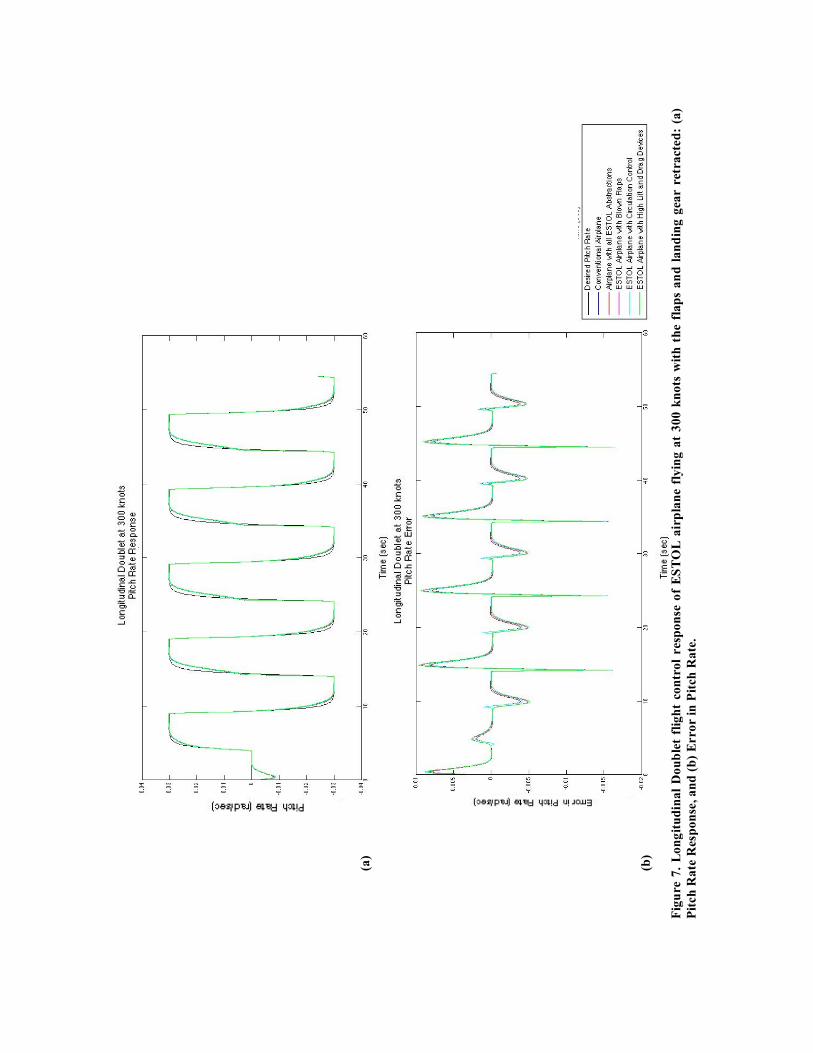
Simulations are conducted to analyze the performance of the direct-adaptive control architecture for ESTOL design abstractions using the Research Aircraft Simulation Modeling Tool. The responses of the conventional aircraft configuration and four ESTOL configurations during longitudinal doublet maneuvers are evaluated. The conventional configuration represents the generic transport airplane, with no ESTOL technology. The first ESTOL configuration shown in the figures is indicated as having all ESTOL abstractions. This configuration represents the generic transport airplane with blown flaps, active circulation control, high lift devices, and high drag devices. (The normalized thrust coefficient for the active circulation control was equal to one for the analysis, designating full or maximum bleed air.) The remaining ESTOL configurations are labeled appropriately as representing the generic transport airplane with either the blown flaps only, the active circulation control only (with the normalized thrust coefficient equal to one), or the high lift and drag devises only.
In all cases, the model of the aircraft used by the controller is that of the conventional aircraft—the dynamics of the ESTOL technologies are unknown to the controller. Results show that the adaptive controller is successful in controlling all configurations of the research aircraft simulation, despite the presence of the unmodeled dynamics. Figure 7 provides the aircrafts’ pitch rate response and error in pitch rate for all the configurations simulated at approximately 300 knots with the flaps and landing gear retracted; Fig. 8 provides the aircrafts’ pitch rate response and error in pitch rate for all the configurations simulated at approximately 105 knots with the flaps and landing gear deployed.
The performance at two flight conditions, 300 knots and 105 knots, is provided to demonstrate the variation in performance with respect to the prominence of the ESTOL abstractions. As described in Section II, the dynamic effects of the blown flaps and circulation control are inversely proportional to the dynamic pressure. Likewise, the dynamic effects of the blown flaps are directly related to the deflection of the flaps. The effects of these ESTOL abstractions are, therefore, less prominent at higher airspeeds and for clean configurations. For the 300 knots flight condition, with the flaps and landing gear retracted, the effects of the ESTOL abstraction are small and the responses of the various aircraft to longitudinal doublets are, consequently, very similar. As shown in Fig. 7, the aircraft with all ESTOL abstractions follows the desired pitch rate most closely, followed by the aircraft with circulation control. This can be accounted for by the slight increase in maneuverability provided by the abstractions. As the aircrafts progresses through the longitudinal doublets, the flight controller adapts to account for errors and the response characteristics change. Over time, the adaptation causes the pitch rate response to lag when the direction of the pitch rate changes, but the total error in pitch rate still decreases for all configurations. For the 105 knots flight condition, with the flaps and landing gear deployed, the effects of the ESTOL abstractions are most distinguished, and this is seen in the variation in flight performance. The most noticeable difference between the aircraft’s performances is that the aircraft with all ESTOL abstractions and blown flaps are
successful in achieving both the positive and negative pitch rates while the conventional aircraft and the aircraft with circulation control and high lift and drag devices only achieve the negative pitch rate. These aircraft (the conventional aircraft and the aircraft with circulation control and high lift and drag devices) are incapable of maintaining the pitch up rates because the resulting attitude at the low speed causes the aircraft to stall. The aircraft subsequently loose pitch up authority and altitude before recovering during the negative pitch rate portion of the doublet maneuver. The adaptation of the controller has little effect on the error, and the flight characteristics remain oscillatory. The only noticeable change in the pitch rate response over time is in the settling time for the negative pitch rate; the settling time decreases for the aircraft with circulation control and settling time increases for the conventional aircraft and the aircraft with high lift and drag devises.
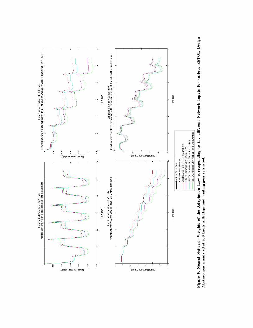
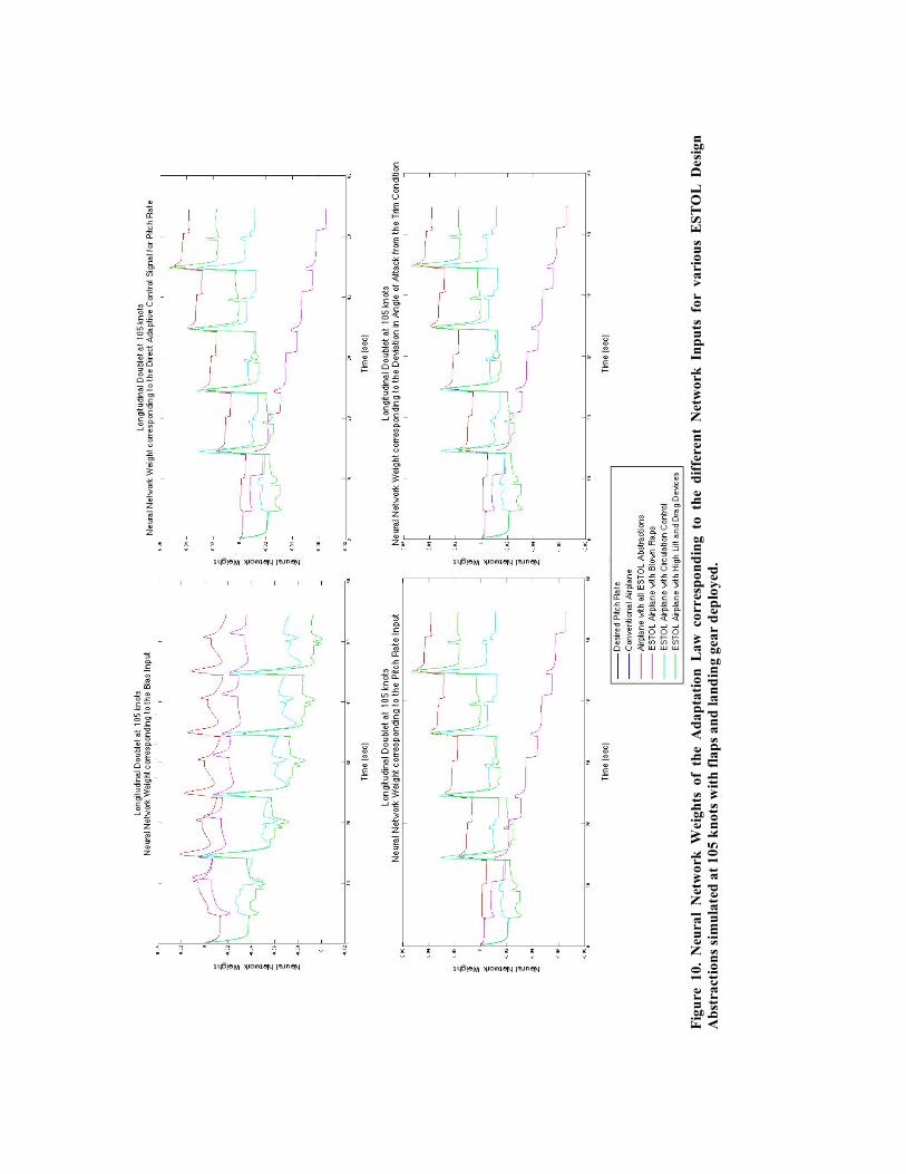
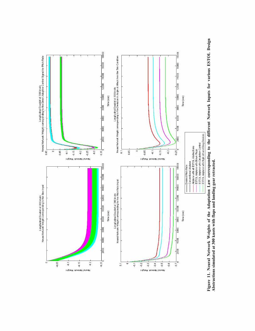
The adaptation of the flight controller is captured by the change in the neural network weights during the longitudinal maneuver. Figures 9 and 10 show the adaptation of four neural network weights during the longitudinal maneuver for all the configurations at the 300 and 105 knots flight conditions, respectively. In these figures, the adaptation forms a pattern repeated for each doublet that progresses either in the upwards or downward direction. For the 300 knots flight condition, the pattern for the weight adaptation appears uniform for all the aircraft configurations. For the 105 knots flight condition the patterns differ for the different aircraft configurations. This is representative of the difference in flight dynamics caused by the ESTOL abstractions at the slow airspeed and with flaps extended. In the time span shown for the five doublets, the weights do not converge to a single value or a range of values. After a large number of doublets (over 1000 and 500 doublets for the 300 and 105 knots flight conditions, respectively), however, the weights do converge to range of values while maintaining the same repetitive pattern for each doublet. The final range is not considered to be globally optimal and, as shown in Fig. 11 and 12, the final range and the transitory behavior of the weights are not reflected in the initial progressions shown in Fig. 9 and 10.
V. Future Work The Research Aircraft Simulation Modeling Tool has been a valuable resource in the evaluation of the
direct-adaptive control architecture with respect to the various ESTOL design abstractions. The Research Aircraft Simulation Modeling Tool will continue to serve as a tool for further evaluation of the direct adaptive control architecture and for research of new intelligent control technologies.
Future research will focus on novel control architectures and algorithms to meet the challenges and performance goals of ESTOL flight control. The ESTOL design abstractions, which were controlled successfully for the limited study in this paper, present numerous technologies challenges for flight control requiring precise control of both airspeed and attitude. There are two main reasons for this: first, the ESTOL technologies tightly couple, and complicate, the engine dynamics and aerodynamics; and second, unlike conventional transport aircraft that remain on the front side of the power curve during flight, an ESTOL transport aircraft transitions between the front and backside of the power curve for take off and landing. In the course of this transition, the flight dynamics of the vehicle and the response characteristics due to control inputs change drastically. In order to address these challenges, we will research predictive control methodologies, along with online learning techniques, that will help integrate the flight and propulsion control.
Summary In previous studies, direct-adaptation control architectures has been shown to reduce the tracking error
and increase the robustness of the control law by explicitly addressing uncertainty in aircraft dynamics and changes to the system due to damage or failure.4-7 In this study, we examine the benefits of a direct-adaptive control architecture that is capable of adapting to the uncertainties and changes in the ESTOL flight dynamics. A dynamic inversion based direct-adaptive control architecture is implemented and tested using an ESTOL simulation capability that was specifically developed for this study. The simulation is capable of emulating many different ESTOL design abstractions, include blown flaps, active and passive circulation control, high lift devices, and high drag devices. In our study, we analyze the ESTOL vehicle performance for various flight conditions and ESTOL design variations, and demonstrate the ability of direct-adaptive control architecture to control the simulated ESTOL aircraft, despite the presence of unmodeled dynamics.
Acknowledgments The authors would like to thank Craig Hange, Chad Frost, Douglas Wardwell, John Zuk and Nhan
Nguyen of NASA Ames Research Center for their contribution to the development and evaluation of the Research Aircraft Simulation Modeling Tool.
References 1“Fundamental Aeronautics Program Subsonic Fixed Wing Project Reference Document,” National Aeronautics
and Space Administration, May 2006, URL: http://www.aeronautics.nasa.gov/programs_fap.htm 2Hange, C., “Trajectory Kinematics of a Simultaneous Non-Interfering landing Approach, and the Impact on
ESTOL Regional Transport Performance and Flight Control,” AIAA’s 3rd Annual Aviation Technology, Integration and Operations Tech Conference, AIAA, Denver, Colorado, November 2003, AIAA 2003-6857
3Norton, B., “STOL Progenitors: The Technology Path to a Large STOL Aircraft and the C-17A, AIAA Case Study, AIAA, Reston, Virginia, 2002, pp. 1
4Kaneshige, J., Bull, J. and Totah, J. J., “Generic Neural Flight Control and Autopilot System,” AIAA Guidance, Navigation and Control Conference and Exhibit, Denver, Colorado, August 2000, AIAA-2000-4281
5Nguyen, N., Bakhtiari-Nejad, M., Huang, Y., “Hybrid Adaptive Flight Control with Bounded Linear Stability Snalysis,” AIAA Guidance, Navigation and Control Conference and Exhibit, AIAA, Hilton Head, South Carolina, August 2007, AIAA-2007-6422
6Nguyen, N., Krishnakumar, K., Kaneshige, J. T. and Nespeca, P., “Dynamic, Adaptive Control, and Stability Recovery of Damaged Asymmetric Aircraft,” AIAA Journal of Guidance, Control and Dynamics (to be published)
7Burken, J. J., Williams-Hayes, P., Kaneshige, J. T. and Stachowiak, S. J., “Reconfigurable Control with Neural Network Augmentation for a Modified F-15 Aircraft,” NASA/TM-2006-213678, April 2006
8Chowdhary, G., Johnson, E. N., “Adaptive Neural Network Flight Control Using both Current and Recorded Data,” AIAA Guidance, Navigation and Control Conference and Exhibit, AIAA, Hilton Head, South Carolina, August 2007, AIAA-2007-6505
9Blake, M. W., “The NASA Advanced Concepts Flight Simulator—A Unique Transport Aircraft Research Environment,” AIAA Flight Simulation Technologies Conference, AIAA, San Diego, California, July 1996, AIAA-96-3518
10Collins, S., Sato, R., White, D., “Extreme Short Takeoff and Landing Aircraft Dual-Use Technology Study,” Northrop Grumman Corporation, November 2005
11Bevilaqua, P., “ESTOL Final Report for Task 9 of the Research and Development Program Advanced Aircraft Systems Extreme Short Take-Off and Landing Dual Use Technology Study,” Lockheed Martin Corporation, December 2005
12Manley, D. J., Garyson, B., “ESTOL Aircraft Military/Civil Dual-Use Technology Study,” The Boeing Company, December 2005
13Stephenson, S. D., Hardy, G. H., “Longitudinal Stability and Control Characteristics of the Quiet Short-Haul Research Aircraft (QSRA),” NASA Technical Paper 2965, 1989
14Stephenson, J. D., Jeske, J. A., Hardy, G. H., “Lateral-Directional Stability and Control Characteristics of the Quiet Short-Haul Research Aircraft (QSRA),” NASA Techical Memorandum 102250, May 1990
15Papp, P. P., Quam, R. A., Freeman, G. A., “STOL Tactical Aircraft Investigation -- Externally Blown Flaps, Analysis of Wind Tunnel Data,” Los Angeles Aircraft Division, Rockwell International Corporation, Technical Report AFFDL-TR-73-20, Volume IV, April 1973
16Keen, E. B., Mason, W. H., “A Conceptual Design Method for Predicting the Aerodynamics of Upper Surface Blowing on Airfoils and Wings,” AIAA’s 23rd Applied Aerodynamics Conference, AIAA, Toronto, Ontario, Canada, June 2005, AIAA-2005-5216
17Bobbitt, P. J., Margason, R., “Analysis of the Take-Off and Landing of Powered-Lift Aircraft,” AIAA’s 45th Aerospace Sciences Meeting and Exhibit, AIAA, Reno, Nevada, January 2007, AIAA-2007-1256
18De la Montanya, J. B., Marshall, D. D., “Circulation Control and Its Application to Extreme Short Take-Off and Landing Vehicles,” AIAA’s 45th Aerospace Sciences Meeting and Exhibit, AIAA, Reno, Nevada, January 2007, AIAA-2007-1404
19Enns, D., Bugajski, D., Hendrick, R., Stein, G., “Dynamic inversion: an evolving method for flight control design,” International Journal of Control, Vol. 59, No. 1, 1994, pp 71-91.
Ta
ble
1
. T
he
air
cra
ft
com
po
nen
ts
aff
ect
ed
by
th
e im
ple
men
tati
on
o
f ea
ch
ES
TO
L
ab
stra
ctio
n
are
ind
ica
ted
by
th
e !
s.
Ta
ble
2.
Th
e a
ero
dy
na
mic
an
d t
hru
st f
orc
es a
nd
mo
men
ts m
od
ifie
d f
or
each
air
cra
ft c
om
po
nen
t d
ue
to
the
imp
lem
enta
tio
n o
f a
ll E
ST
OL
des
ign
ab
stra
ctio
ns
are i
nd
ica
ted
by
th
e !
s.
(a)
(b
)
(c)
Fig
ure
1.
Th
e ef
fect
s o
f b
low
n f
lap
s fo
r (a
) th
e C
oef
ficie
nt
of
Lif
t o
ver
Dra
g v
ersu
s A
irsp
eed
, (b
) th
e C
oef
ficie
nt
of
Lif
t v
ers
us
An
gle
of
Att
ack
, a
nd
(c)
the C
oef
fici
ent
of
Dra
g v
ers
us
An
gle
of
Att
ack
.
(a)
(b
)
(c)
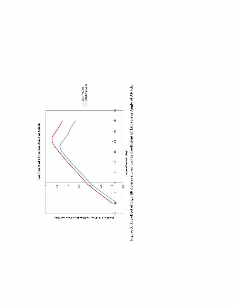
Fig
ure
3.
Th
e ef
fect
of
hig
h l
ift
dev
ises
sh
ow
n f
or
the C
oeff
icie
nt
of
Lif
t v
ers
us
An
gle
of
Att
ack
.
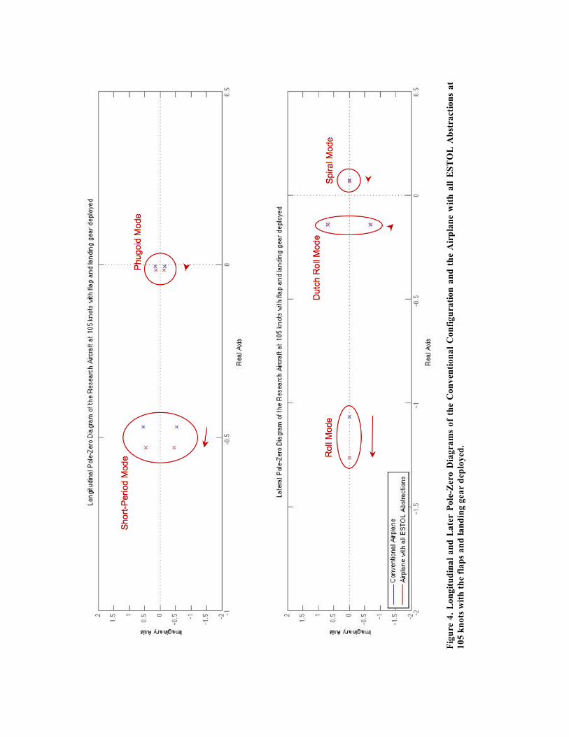
F
igu
re 4
. L
on
git
ud
ina
l a
nd
La
ter
Po
le-Z
ero
Dia
gra
ms
of
the
Co
nv
enti
on
al
Co
nfi
gu
rati
on
an
d t
he
Air
pla
ne w
ith
all
ES
TO
L A
bst
ract
ion
s a
t
10
5 k
no
ts w
ith
th
e f
lap
s a
nd
la
nd
ing
gea
r d
eplo
yed
.
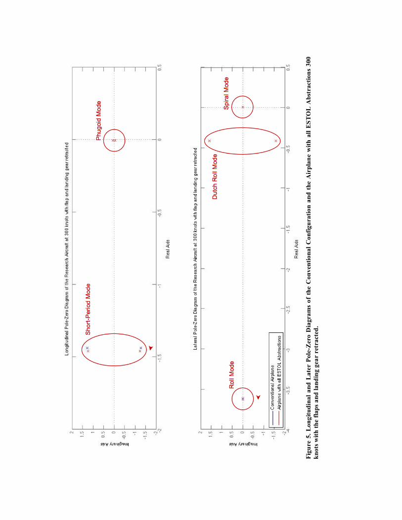
F
igu
re 5
. L
on
git
ud
ina
l a
nd
La
ter
Po
le-Z
ero
Dia
gra
ms
of
the
Co
nv
enti
on
al
Co
nfi
gu
rati
on
an
d t
he
Air
pla
ne
wit
h a
ll E
ST
OL
Ab
stra
ctio
ns
30
0
kn
ots
wit
h t
he f
lap
s a
nd
la
nd
ing
gea
r re
tra
cted
.
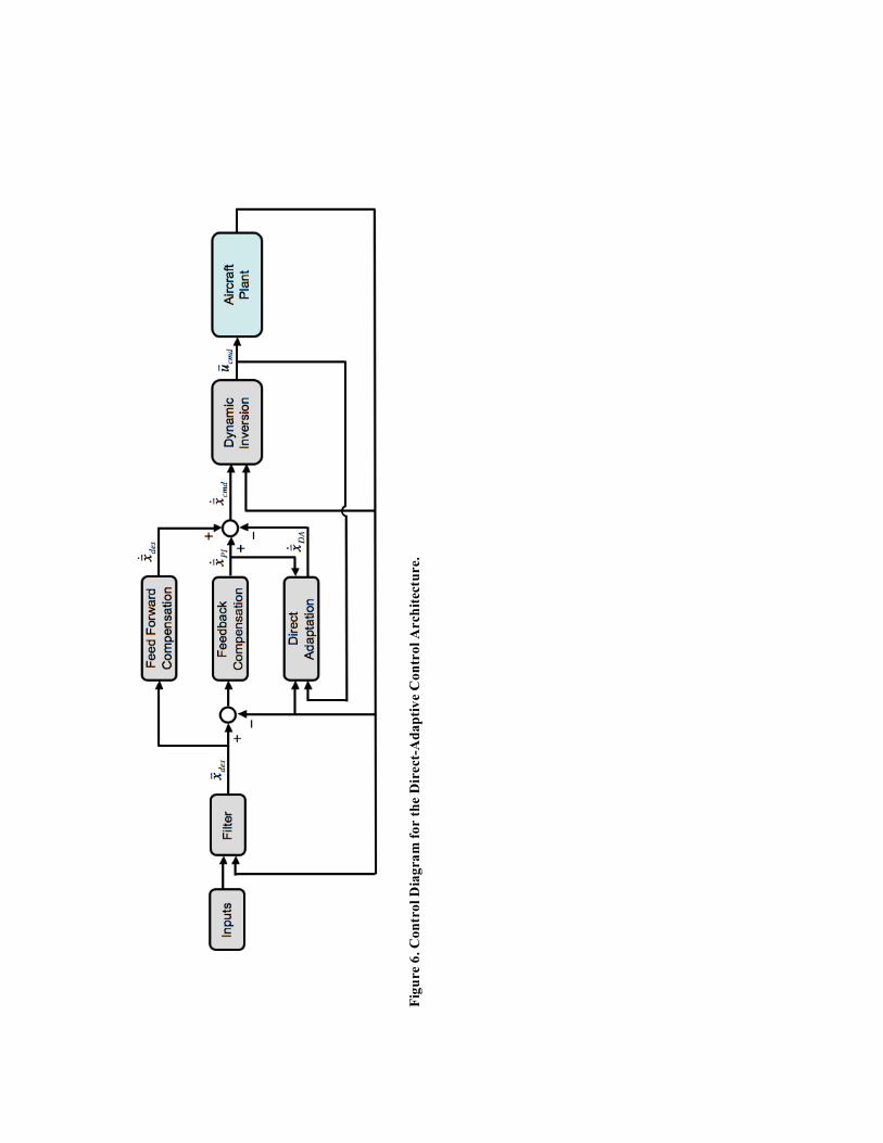
F
igu
re 6
. C
on
tro
l D
iag
ram
fo
r t
he D
irect
-Ad
ap
tiv
e C
on
tro
l A
rch
itec
ture.
(a)
(b)
Fig
ure
7.
Lo
ng
itu
din
al
Do
ub
let
flig
ht
con
tro
l res
po
nse
of
ES
TO
L a
irp
lan
e fl
yin
g a
t 3
00
kn
ots
wit
h t
he
fla
ps
an
d l
an
din
g g
ear
retr
act
ed
: (a
)
Pit
ch
Ra
te R
esp
on
se, a
nd
(b
) E
rro
r i
n P
itch
Ra
te.

(a)
(b)
Fig
ure
8.
Lo
ng
itu
din
al
Do
ub
let
flig
ht
con
tro
l re
spo
nse
of
ES
TO
L a
irp
lan
e fl
yin
g a
t 1
05
kn
ots
wit
h t
he f
lap
s a
nd
la
nd
ing
gea
r d
eplo
yed
: (a
)
Pit
ch
Ra
te R
esp
on
se, a
nd
(b
) E
rro
r i
n P
itch
Ra
te.
Fig
ure
9
. N
eura
l N
etw
ork
W
eig
hts
o
f th
e A
da
pta
tio
n L
aw
co
rres
po
nd
ing
to
th
e d
iffe
ren
t N
etw
ork
In
pu
ts
for
va
rio
us
ES
TO
L
Des
ign
Ab
stra
ctio
ns
sim
ula
ted
at
30
0 k
no
ts w
ith
fla
ps
an
d l
an
din
g g
ear
retr
act
ed
.
Fig
ure
1
0.
Neu
ral
Net
wo
rk W
eig
hts
o
f th
e A
da
pta
tio
n L
aw
co
rres
po
nd
ing
to
th
e d
iffe
ren
t N
etw
ork
In
pu
ts fo
r v
ari
ou
s E
ST
OL
D
esi
gn
Ab
stra
ctio
ns
sim
ula
ted
at
10
5 k
no
ts w
ith
fla
ps
an
d l
an
din
g g
ear
dep
loy
ed.
Fig
ure
1
1.
Neu
ral
Net
wo
rk W
eig
hts
o
f th
e A
da
pta
tio
n L
aw
co
rre
spo
nd
ing
to
th
e d
iffe
ren
t N
etw
ork
In
pu
ts fo
r v
ari
ou
s E
ST
OL
D
esig
n
Ab
stra
ctio
ns
sim
ula
ted
at
30
0 k
no
ts w
ith
fla
ps
an
d l
an
din
g g
ear
retr
act
ed
.
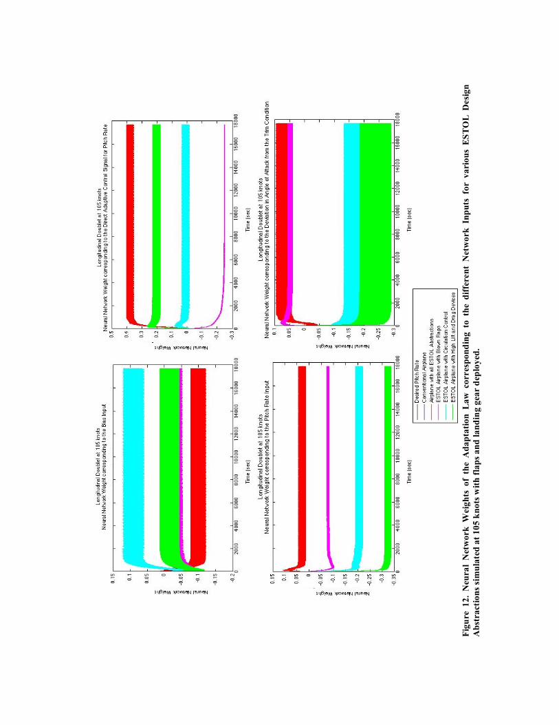
Fig
ure
1
2.
Neu
ral
Net
wo
rk W
eig
hts
o
f th
e A
da
pta
tio
n L
aw
co
rres
po
nd
ing
to
th
e d
iffe
ren
t N
etw
ork
In
pu
ts fo
r v
ari
ou
s E
ST
OL
D
esi
gn
Ab
stra
ctio
ns
sim
ula
ted
at
10
5 k
no
ts w
ith
fla
ps
an
d l
an
din
g g
ear
dep
loy
ed.