


Adaptive Antenna Systems: Overview - TKK · PDF file · 2016-01-28Adaptive Antenna...
49
Helsinki University of Technology S-72.333 Postgraduate Course in Radio Communications (2004/2005) Adaptive Antenna Systems: Overview Hafeth Hourani [email protected]
Transcript of Adaptive Antenna Systems: Overview - TKK · PDF file · 2016-01-28Adaptive Antenna...

Helsinki University of Technology
S-72.333 Postgraduate Course in Radio Communications (2004/2005)
Adaptive Antenna Systems: Overview
Hafeth [email protected]

/Title/ 17.01.2005 [email protected] 2
Presentation Outline
OverviewMotivationFundamentalsSystem ModelAdaptation Algorithms ConclusionsReferences & Exercise

/Title/ 17.01.2005 [email protected] 3
Next . . .
OverviewMotivationFundamentalsSystem ModelAdaptation AlgorithmsConclusionsReferences & Exercise

/Title/ 17.01.2005 [email protected] 4
Antennas
AntennaCouples electromagnetic energy from one medium (space) to another (e.g., wire, coaxial cable, waveguide)
Omnidirectional Antennas
Directional Antennas

/Title/ 17.01.2005 [email protected] 5
Antenna Systems (1/2)
Sectorized SystemsSubdivide the area into sectors
Increases the frequency reuse

/Title/ 17.01.2005 [email protected] 6
Antenna Systems (2/2)
Diversity SystemsMultiple antenna elements
Switched DiversitySwitch between antennas
Diversity combiningCombine multipath signals
Smart Systems our topic
Com
bined diversitySw
itched diversity

/Title/ 17.01.2005 [email protected] 7
Who is Smart?
Antennas are not smart!Antenna Systems could be smart!
Smart Antenna SystemsConsists of M antenna elements (Antenna Array)Each antenna element signals are processed adaptivelyControlled by DSP Adapts to the RF environments

/Title/ 17.01.2005 [email protected] 9
Smart Antenna System Types
Smart Antennas
Phased Array Antennas(Multibeam Antennas)
Adaptive Array Antennas(Adaptive Antennas)
Finite number of fixed, predefined patterns or combining strategies
Infinite number of patterns (scenario-based) that are adjusted in real time

/Title/ 17.01.2005 [email protected] 10
Multibeam Antenna Systems
WhatMultiple fixed beams with heightened sensitivity in particular direction
HowDetect signal strengthChoose from one of several predefined, fixed beamsSwitch from one beam to another

/Title/ 17.01.2005 [email protected] 11
Adaptive Antennas
The most advanced smart antenna approachUses a variety of DSP algorithms Dynamically minimizes interference and maximizes intended signal reception

/Title/ 17.01.2005 [email protected] 12
Next . . .
OverviewMotivationFundamentalsSystem ModelAdaptation AlgorithmsConclusionsReferences & Exercise

/Title/ 17.01.2005 [email protected] 13
Features
Signal GainMultipath components are combined (improved SNR)
Interference RejectionImproved signal to interference ratio (SIR)
Spatial DiversityMinimizes the multipath fading
Power EfficiencyImproved processing gain

/Title/ 17.01.2005 [email protected] 14
Benefits (1/3)
Reduction in co-channel interferenceThe radiated energy is focused in the form of narrow beams only in the desired direction ⇒ Spatial Filtering
Mitigating multipath effectsThe multipath can be either mitigated as the interference, or it can be constructively exploited to enhance the system performance
Capacity IncreaseBy mitigating the interference, the system capacity improves

/Title/ 17.01.2005 [email protected] 15
Benefits (2/3)
Range Improvement (Beamforming gain)Focusing the cell energy in one direction increases the range
Power EfficiencyEnergy is radiated in the desired direction only (no waste of energy in other directions)
SecurityIt is more difficult to tap a connection when smart antennas are used
To tap a connection, the intruder must be positioned in the samedirection as the user seen by the BS

/Title/ 17.01.2005 [email protected] 16
Benefits (3/3)
Reduction in handoffNo need for splitting the cells for the sake of improved capacity.
Spatial informationSpatial information of the users are available on demand
CompatibilityThis technology can be applied to various multiple access techniques such as TDMA, FDMA, and CDMA.

/Title/ 17.01.2005 [email protected] 17
Drawbacks
Transceiver ComplexityThe transceiver is much more complex than the conventional one
Resource ManagementNew demand for mobility management
Physical SizeFor a reasonable gain, several antenna elements are required. This could provide some problems

/Title/ 17.01.2005 [email protected] 18
Impacts on Radio Planning
Some of traditional strategies of radio planning has to be modified
From adaptive antenna point of view, it is much more efficient to position the BST away from the road or railway
This way, the spatial dimension is better exploited
Better spatial information is available
Placing the BST along the roads

/Title/ 17.01.2005 [email protected] 19
Applications
Key technology for capacity increase in 3G networksPotential candidate for next generation Wi-Fi and WiMAX systemsElectronic Warfare (EWF)
/Title/ 17.01.2005 [email protected] 20
Next . . .
OverviewMotivation
FundamentalsSystem ModelAdaptation AlgorithmsConclusionsReferences & Exercise

/Title/ 17.01.2005 [email protected] 21
Adaptive Antenna System
An adaptive antenna system consists of several antenna elements, whose signals are processedadaptively in order to exploit the spatial dimensionof the mobile radio channel
Adaptive antenna BTS Conventions BTS radiation pattern

/Title/ 17.01.2005 [email protected] 22
Beamforming (beam steering)
Beamforming = phase the antenna array elementsDirection-of-Arrival (DoA)
The only needed parameter
/Title/ 17.01.2005 [email protected] 23
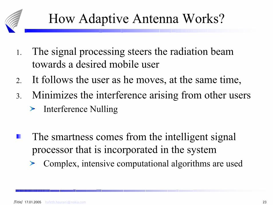
How Adaptive Antenna Works?
1. The signal processing steers the radiation beam towards a desired mobile user
2. It follows the user as he moves, at the same time,3. Minimizes the interference arising from other users
Interference Nulling
The smartness comes from the intelligent signal processor that is incorporated in the system
Complex, intensive computational algorithms are used

/Title/ 17.01.2005 [email protected] 24
Basic Mechanisms
The following functions are performedDirection of arrival (DoA) is estimated for all incoming signals, including the interfering and multipath signalsThe desired user signal is identifiedThe beam is steered in the direction of the desired signalThe user is tracked while he moves Nulls are placed in the interfering signal direction

/Title/ 17.01.2005 [email protected] 25
Next . . .
OverviewMotivationFundamentals
System ModelAdaptation AlgorithmsConclusionsReferences & Exercise

/Title/ 17.01.2005 [email protected] 26
The Mathematical Model (1/10)
Σ
Adaptive Algorithm
wM
w2
w1
Φ
( )z t
uM
u1
u2

/Title/ 17.01.2005 [email protected] 27
The Mathematical Model (2/10)
The phase difference between the antenna element mand a reference element at origin is given by
Where: and are the eve lavation and azimuth angles respectivelyis the phase propagation factor
are the coordinates of antenna element m withwith respect to a reference element at origin
( ) ( ) ( ) ( ) ( ) ( )( )cos sin cos sin cos sinm m
m m m
d
x y z
β
β
∆Ψ = ∆
= Φ Θ + Φ Θ + Φ Θ
ΘΦβ
, ,m m mx y z

/Title/ 17.01.2005 [email protected] 28
The Mathematical Model (3/10)
The output signal can be represented as
( )1
( )M
i ii
z t u t w=
= ∑

/Title/ 17.01.2005 [email protected] 29
The Mathematical Model (4/10)
If the received at the reference antenna element is the the received signals at the other elements will be a phase shifted replicas of
For one user, the output signal can be represented as
And in more compact form
( )1u t
( )1u t
( ) ( ) ( ) ( ) ( ) ( ) ( ) ( )( )cos sin cos sin cos sin1
1
i i iM
j x y z w
iz t u t e β− Φ Θ + Φ Θ + Φ Θ
=
=∑
( ) ( )Hw uz t t=
i

/Title/ 17.01.2005 [email protected] 30
The Mathematical Model (5/10)
Where
Take the first element as a reference so that
The vector is called the Steering Vector( )a ,Φ Θ
( ) ( )( ) ( )
1 2T
1
1
u
a ,
Mj j jt u t e e e
u t
− ∆Ψ − ∆Ψ − ∆Ψ = = Φ Θ
1 0∆Ψ =
Steering Vector

/Title/ 17.01.2005 [email protected] 31
The Mathematical Model (6/10)
The input signal at each antenna element is the convolution between the transmitted signal and the channel impulse response
Where: is the transmitted signal from user iis the channel response between user i and antennaelement j
( ) ( ) ( ), ,ij i iju t s t h tτ τ= ∗
( )is t( ),ijh tτ

/Title/ 17.01.2005 [email protected] 32
The Mathematical Model (7/10)
The channel between the mobile station and the base station can be modeled using the Vector Channel Impulse Response (VCIR) as
Where: is the steering vectoris the channel impulse responseis the time delay of signal of user i to BS through path kthe assumed number of paths of user iis the complex channel gain
( ) ( ) ( ) ( )1
h , a ,iB
i i k k ik kk
t t tτ φ θ α δ τ=
= −∑
a ih i
kτiBikα

/Title/ 17.01.2005 [email protected] 33
The Mathematical Model (8/10)
The complex channel gain
Where is the channel gain, given by
Where is the log-normal shadowing effect for path k of user iis the distance between user i and BS through path kis the path loss exponent of user i through path kis the Doppler Shiftis the phase offset
( ) ( )2 ik ikj f tik ikt e π ψα ρ +=
ikρik
ikik
ik
Adηρ ≈
ikAikdikη
ikfikψ

/Title/ 17.01.2005 [email protected] 34
The Mathematical Model (9/10)
Hence, we can describe the signal at antenna terminal jas
Where is additive noise at antenna element j
( ) ( ) ( ) ( )
( ) ( ) ( )
2
1
2
1
n
n
ijk ik ik
ijk ik ik
Bj j f t
iij i ik kk
Bj j f t
iik i kk
u s t e e t t
e e s t t
π ψ
π ψ
ρ δ τ
ρ τ
− ∆Ψ +
=
− ∆Ψ +
=
= ∗ − +
= − +
∑
∑
( )n i t

/Title/ 17.01.2005 [email protected] 35
The Mathematical Model (10/10)
In channels where the time difference between paths are small relative to the symbol period we can approximate the latest equation as
is called the spatial signature of the narrowband (flatfading) channel
( )s t
( ) ( ) ( )
( ) ( ) ( ) ( )
( ) ( ) ( )
20
1
01
0
n
u a n
b n
ijk ik ik
i
Bj j f t
iij i ikk
B
ii i ik ikk
ii
u s t e e t
s t t t
s t t t
π ψτ ρ
τ φ α
τ
− ∆Ψ +
=
=
= − +
⇒ = − +
= − +
∑
∑
( )b t

/Title/ 17.01.2005 [email protected] 36
Next . . .
OverviewMotivationFundamentalsSystem Model
Adaptation AlgorithmsConclusionsReferences & Exercise

/Title/ 17.01.2005 [email protected] 37
1) Conventional Beamformer
The weights are selected to be the conjugate of the steering vector
For one path case, the weights are selected asWhere c is a real constant
AdvantagesSimple, and provides max. SNR if noise is uncorrelated
DisadvantageDoes not work for mobile communications, since it assumes no directional jammingIn WCDMA, there are many users sharing same frequency
There are many unintentional jammers
Hw a c=

/Title/ 17.01.2005 [email protected] 38
2) Null-Steering Beamformer
If there are Q users in the cell, and the weights are calculated for user i, then the desired weight vector is the solution of the following linear system
The system can be solved if Generally, the problem could be solved as
Where
[ ]
H
H
w a 1
w a 0, 1,i i
i k k Q and k i
=
= ∀ ∈ ≠
Q M≤
( )-1H T H Hw D A A Ai =
[ ] [ ]th1D 0 1 0 0 ,1at thei element, AT
Ma a= =

/Title/ 17.01.2005 [email protected] 39
3) Minimum Variance Distortionless Response Beamformer (MVDR)
Minimize the average output power, while seeking the unity response in the user direction
The obtained weights will minimize the total noise, including interferences and uncorrelated noiseMVDR maximizes the SINR
The problem can be solved using Lagrange Multiplier
( ) 2 H
wmin , subject to w a 1i iE z t =
1H
1R aw , R uu
a R ai
i Hi i
where E−
− = =

/Title/ 17.01.2005 [email protected] 40
4) Minimum Square Error Beamformer
A reference signal is used to calculate the weightsThis reference signal should be known beforehandUsing this signal, the weights can be calculated even without DoA information, or the channel characteristics
The optimum weights can be found as
Where is the training sequence for user i at time k
The achieved weight vector is( )id k
( ) ( )2
w arg min w uHi i iE k d k = −
1 Hw R P, R uu P ui iwhere E and E d− ∗ = = =

/Title/ 17.01.2005 [email protected] 41
5) Least Square Despread/Respread Multitarget Array (LS-DRMTA) (1/2)
This algorithm is based on the respreading of the received data bits. The respreaded signal is compared with the received signal (before despreading) and the difference is used as an error signal
( ).∫
( )Delay τ
( )i iC t τ− ( )iC tinb
Received signal
Respreaded signal
( ) : spreading codeof useriC t i:n received data for userth
inb i

/Title/ 17.01.2005 [email protected] 42
5) Least Square Despread/Respread Multitarget Array (LS-DRMTA) (2/2)
The respreaded signal is given by
The LS-DRMTA is used to minimize the error function by adjusting the weight vector
The cost function is given by
( ) ( ) ( ), 1i in i i b br t b C t n T t nTτ= − − ≤ ≤
( ) ( ) ( ) ( ) ( )22 H
1 1w w x
K K
i ii i ik k
F y k r k k r k= =
= − = −∑ ∑

/Title/ 17.01.2005 [email protected] 43
Other Algorithms
Recursive Mean Square (RMS) algorithmThe Sample Matrix Inversion (SMI) algorithmThe Constant Modulus Algorithm (CMA)The Cyclostationary algorithmThe Decision-Directed algorithms

/Title/ 17.01.2005 [email protected] 44
Next . . .
OverviewMotivationFundamentalsSystem ModelAdaptation Algorithms
ConclusionsReferences & Exercise

/Title/ 17.01.2005 [email protected] 45
Conclusions
Adaptive antenna systems show substantial improvements:
Reduction in co-channel interferenceMitigating multipath effectsCapacity IncreaseRange Improvement (Beamforming gain)Power EfficiencySecurityReduction in handoffSpatial informationCompatibility

/Title/ 17.01.2005 [email protected] 46
Next . . .
OverviewMotivationFundamentalsSystem ModelAdaptation AlgorithmsConclusions
References & Exercise

/Title/ 17.01.2005 [email protected] 47
References
[1] Mohammad Elmusrati, “The smart antenna application in mobile communications,” Helsinki University of Technology, Control Engineering Lab., Lecture Notes, 2002
[2] Per H. Lehne, et. al. “An Overview of smart antenna technology for mobile communication systems”. IEEE Communications, Surveys
[3] International Engineering Consortium, “Smart Antenna Systems”, URL: http://www.iec.org/online/tutorials/acrobat/smart_ant.pdf

/Title/ 17.01.2005 [email protected] 48
Exercise
A base station located at the center of a circular cell. Assume that two users are located at
x = 40m, φ = π/8, and x =190m, φ = 3π/5 with respect to base station.
The carrier frequency is 2 GHz.1. Find the steering vector a for both users2. Calculate the weights vector w1 to null the interference
of user 1 with respect to user 2.3. Calculate the weights vector w2 to null the interference
of user 2 with respect to user 1.


