Adaptec Storage Manager - Thomas-Krenn.AG
182
User’s Guide For Direct Attached Storage Adaptec Storage Manager
Transcript of Adaptec Storage Manager - Thomas-Krenn.AG
User’s GuideFor Direct Attached Storage
Adaptec Storage Manager
● 2
Copyright©2008 Adaptec, Inc. All rights reserved. No part of this publication may be reproduced, stored in a retrieval system, or transmitted in any form or by any means, electronic, mechanical, photocopying, recording or otherwise, without the prior written consent of Adaptec, Inc., 691 South Milpitas Blvd., Milpitas, CA 95035.
TrademarksAdaptec, Storage Manager, and the Adaptec logo are trademarks of Adaptec, Inc., which may be registered in some jurisdictions.
Microsoft and Windows are trademarks of Microsoft Corporation in the US and other countries, used under license.
Red Hat is a trademark of Red Hat, Inc. in the US and other countries, used under license.
SCO and OpenServer are trademarks of The SCO Group, Inc. in the US and other countries, used under license.
UnixWare is a registered trademark of The Open Group in the US and other countries, used under license.
VMWare is a registered trademark of VMWare, Inc. in the US and other countries, used under license.
All other trademarks are the property of their respective owners.
ChangesThe material in this document is for information only and is subject to change without notice. While reasonable efforts have been made in the preparation of this document to assure its accuracy, Adaptec, Inc. assumes no liability resulting from errors or omissions in this document, or from the use of the information contained herein.
Adaptec reserves the right to make changes in the product design without reservation and without notification to its users.
DisclaimerIF THIS PRODUCT DIRECTS YOU TO COPY MATERIALS, YOU MUST HAVE PERMISSION FROM THE COPYRIGHT OWNER OF THE MATERIALS TO AVOID VIOLATING THE LAW WHICH COULD RESULT IN DAMAGES OR OTHER REMEDIES.
● 3
Adaptec Customer SupportIf you have questions about installing or using your Adaptec product, check this document first—you will find answers to most of your questions. If you need further assistance, use the support options listed below. To expedite your service, have your computer in front of you.
Technical Support Identification (TSID) Number● Before contacting Technical Support, you need your unique 12-digit TSID number. The TSID number identifies your product
and support status.
● The TSID number is included on a white, bar-coded label, like this example:
● Affix a copy of the TSID label to the CD jacket so that you don’t lose it.
North America ● Visit our Web site at www.adaptec.com.
● Search the Adaptec Support Knowledgebase (ASK) at ask.adaptec.com for articles, troubleshooting tips, and frequently asked questions for your product.
● For information about Adaptec’s support options, call +1 408-957-2550, 24 hours per day, 7 days per week. To speak with a Technical Support Specialist, call +1 408-934-7274 or +1 321-207-2000.
● For support via e-mail, submit your question at ask.adaptec.com.
● You can order Adaptec products, including accessories and cables, by calling +1 408-957-7274. Or, you can order cables online at www.adaptec.com/en-US/products/cables/.
Europe ● Visit our Web site at www.adaptec.com/worldwide.
● German: Call +49 89 43 66 55 22. For support via e-mail, submit your question at ask-de.adaptec.com.
● French: Call +49 89 43 66 55 33. For support via e-mail, submit your question at ask-fr.adaptec.com.
● English: Call +49 89 43 66 55 44. For support via e-mail, submit your question at ask.adaptec.com.
● You can order Adaptec cables online at www.adaptec.com/en-US/products/cables.
Japan ● Visit our Web site at www.adaptec.co.jp.
● Call +81-0044-2213-2601.
● 4
Software License AgreementPLEASE READ CAREFULLY: THE USE OF THIS SOFTWARE IS SUBJECT TO THE SOFTWARE LICENSE TERMS OF ADAPTEC, INC. AND OTHER LICENSORS WHOSE SOFTWARE MAY BE BUNDLED WITH THIS PRODUCT.
BY YOUR USE OF THE SOFTWARE INCLUDED WITH THIS PRODUCT YOU AGREE TO THE LICENSE TERMS REQUIRED BY THE LICENSOR OF THAT SOFTWARE, AS SET FORTH DURING THE INSTALLATION PROCESS. IF YOU DO NOT AGREE TO THE LICENSE TERMS APPLICABLE TO THE SOFTWARE, YOU MAY RETURN THE ENTIRE UNUSED PRODUCT FOR A FULL REFUND.
In return for acquiring a license to use the Adaptec software (“Software”) and the related documentation, you agree to the following terms and conditions:
1. License. This Agreement grants you, the Licensee, a license to:
● Use the Software on a single computer system or on multiple workstations, systems and servers which incorporate an Adaptec RAID controller and may be accessed by multiple users from multiple locations. You may make as many installations of the Software as needed, but must restrict such installation only to systems, workstations or servers using an Adaptec RAID controller.
● Make one copy of the Software in machine readable form solely for back-up purposes provided you reproduce Adaptec’s copyright notice and any proprietary legends.
2. Restrictions. You may not distribute copies of the Software to others. You may not post or otherwise make available the Software, or any portion thereof, in any form, on the Internet. You may not use the Software in a computer service business, including in time sharing applications. The Software contains trade secrets and, in order to protect them, you may not decompile, reverse engineer, disassemble, or otherwise reduce the Software to a human-perceivable form. YOU MAY NOT MODIFY, ADAPT, TRANSLATE, RENT, LEASE, LOAN, RESELL FOR PROFIT, DISTRIBUTE, NETWORK OR CREATE DERIVATIVE WORKS BASED UPON THE SOFTWARE OR ANY PART THEREOF.
3. Ownership of Software. As Licensee, you own the media upon which the software is recorded or fixed, but Adaptec and its licensors retain title and ownership of the Software recorded on the original media and all subsequent copies of the Software, regardless of the form or media in which or on which the original and other copies may exist. This license is not a sale of the Software or any copy.
4. Confidentiality. You agree to maintain the Software in confidence and that you will not disclose the Software to any third party without the express written consent of Adaptec. You further agree to take all reasonable precautions to preclude access of unauthorized persons to the Software.
5. Term. This license is effective until January 1, 2045, unless terminated earlier. You may terminate the license at any time by destroying the Software (including the related documentation) together with all copies or modifications in any form. Adaptec will have the right to terminate our license immediately if you fail to comply with any term or condition of this Agreement. Upon any termination, including termination by you, you must destroy the Software (including the related documentation), together with all copies or modifications in any form.
6. Special Terms Applicable to Databases. Where a database is included with the Software, you acknowledge that it is licensed only in connection with the use of the Software to perform disc creation, and that the database and all data derived therefrom must be maintained in confidence in accordance with the provisions of Section 4. This license does not grant you any rights to distribute or disclose such database or data.
7. Limited Warranty. Adaptec and its Licensor warrant only that the media upon which the Software is furnished will be free from defects in material or workmanship under normal use and service for a period of thirty (30) days from the date of delivery to you. ADAPTEC AND ITS LICENSORS DO NOT AND CANNOT WARRANT THE PERFORMANCE OR RESULTS YOU MAY OBTAIN BY USING THE SOFTWARE OR DOCUMENTATION. THE FOREGOING STATES THE SOLE AND EXCLUSIVE REMEDIES ADAPTEC AND ITS LICENSORS WILL PROVIDE FOR BREACH OF WARRANTY. EXCEPT FOR THE FOREGOING LIMITED WARRANTY, ADAPTEC AND ITS LICENSORS MAKE NO WARRANTIES, EXPRESSED OR IMPLIED, INCLUDING, BUT NOT LIMITED, AS TO NON-INFRINGEMENT OF THIRD PARTY RIGHTS, MERCHANTABILITY OR FITNESS FOR A PARTICULAR PURPOSE. Some states do not allow the exclusion of implied warranties or limitations on how long an implied warranty may last, so the above limitations may not apply to you. This warranty gives you specific legal rights and you may also have other rights which vary from state to state.
8. The entire liability of Adaptec and its licensors, and your exclusive remedy for a breach of this warranty, shall be:
● The replacement of any media not meeting the above limited warranty which is returned to Adaptec; or:
● If Adaptec or its distributor is unable to deliver replacement media which is free from defects in materials or workmanship, you may terminate this Agreement by returning the Software and your money will be refunded.
9. Limitation of Liability. IN NO EVENT WILL ADAPTEC OR ITS LICENSORS BE LIABLE TO YOU FOR ANY INCIDENTAL, CONSEQUENTIAL OR INDIRECT DAMAGES, INCLUDING ANY LOST PROFITS, LOST SAVINGS, OR LOSS OF DATA, EVEN IF ADAPTEC OR A LICENSOR HAS BEEN ADVISED OF THE POSSIBILITY OF SUCH DAMAGES, OR FOR ANY CLAIM BY ANY OTHER PARTY. Some states do not allow the exclusion or limitation of special, incidental, or consequential damages, so the above limitation or exclusion may not apply to you.

● 5
10. Export. You acknowledge that the laws and regulations of the United States and other countries may restrict the export and re-export of the Software. You agree that you will not export or re-export the Software or documentation in any form in violation of applicable United States and foreign law.
11. Government Restricted Rights. The Software is subject to restricted rights as follows. If the Software is acquired under the terms of a GSA contract: use, reproduction or disclosure is subject to the restrictions set forth in the applicable ADP Schedule contract. If the Software is acquired under the terms of a DoD or civilian agency contract, use, duplication or disclosure by the Government is subject to the restrictions of this Agreement in accordance with i C.F.R. 12.212 of the Federal Acquisition Regulations and its successors and 49 C.F.R. 227.7202-1 of the DoD FAR Supplement and its successors.
12. General. You acknowledge that you have read this Agreement, understand it, and that by using the Software you agree to be bound by its terms and conditions. You further agree that it is the complete and exclusive statement of the agreement between Adaptec and you, and supersedes any proposal or prior agreement, oral or written, and any other communication between Adaptec and you relating to the subject matter of this Agreement. No additional or any different terms will be enforceable against Adaptec unless Adaptec gives its express consent, including an express waiver of the terms of this Agreement, in writing signed by an officer of Adaptec. You assume full responsibility for the use of the Software and agree to use the Software legally and responsibly. This Agreement shall be governed by California law, except as to copyright matters, which are covered by Federal law. This Agreement is deemed entered into at Milpitas, California by both parties. Should any provision of this Agreement be declared unenforceable in any jurisdiction, then such provision shall be deemed severable from this Agreement and shall not affect the remainder hereof. All rights in the Software not specifically granted in this Agreement are reserved by Adaptec.
Should you have any questions concerning this Agreement, you may contact Adaptec by writing to:
Adaptec, Inc.Legal Department691 South Milpitas BoulevardMilpitas, California 95035.
ContentsAbout This Guide
How This Guide is Organized .......................................................................... 11
What You Need to Know Before You Begin ................................................... 11
Terminology Used in this Guide ...................................................................... 11
Part I: Getting Started
1 Introduction to Adaptec Storage ManagerGetting Started Checklist .................................................................................. 14
About Adaptec Storage Manager .................................................................... 14
About the Adaptec Storage Manager Agent ................................................... 14
Growing Your Storage Space with Adaptec Storage Manager........................ 15
System Requirements........................................................................................ 17
Controller Support............................................................................................ 17
2 Installing Adaptec Storage ManagerInstalling on Windows...................................................................................... 19
Installing on Linux............................................................................................ 20
Installing on UnixWare or OpenServer ........................................................... 21
Installing on Solaris........................................................................................... 21
Installing on FreeBSD ....................................................................................... 22
Installing on VMWare ...................................................................................... 22
Using Adaptec Storage Manager with a Firewall............................................. 23
Running Adaptec Storage Manager from the CD ........................................... 23
3 Building Your Storage SpaceOverview............................................................................................................ 26
Choosing a Management System ..................................................................... 26
Contents ● 7
Starting and Logging In on the Local System.................................................. 27
Starting Adaptec Storage Manager on Remote Systems ................................. 31
Logging into Remote Systems from the Local System .................................... 32
Creating Logical Drives..................................................................................... 34
Managing Your Storage Space.......................................................................... 41
Part II: Monitoring and Modifying Your Storage Space
4 Exploring Adaptec Storage ManagerWorking in Adaptec Storage Manager............................................................. 44
Overview of the Main Window........................................................................ 44
Revealing More Device Information................................................................ 49
Checking System Status from the Main Window ........................................... 50
Getting Help ...................................................................................................... 50
Logging Out of Adaptec Storage Manager....................................................... 51
Uninstalling Adaptec Storage Manager ........................................................... 51
5 Protecting Your DataCreating and Managing Hot Spares ................................................................. 54
Creating a Snapshot .......................................................................................... 57
Enabling Copyback ........................................................................................... 59
6 Modifying Your Direct Attached StorageUnderstanding Logical Drives.......................................................................... 61
Creating and Modifying Logical Drives........................................................... 62
Fine-tuning Logical Drives ............................................................................... 65
Optimizing Logical Drive Performance........................................................... 67
Verifying Logical Drives ................................................................................... 68
Increasing the Capacity of a Logical Drive ...................................................... 70
Changing the RAID Level of a Logical Drive................................................... 72
Deleting a Logical Drive.................................................................................... 73
Creating a RAID Volume ................................................................................. 73
Creating a JBOD Disk ....................................................................................... 75
Maintaining an Energy-Efficient Storage Space .............................................. 77
7 Scheduling Recurring or Resource-Intensive JobsScheduling a Task.............................................................................................. 82
Opening the Task Manager .............................................................................. 83
Monitoring Tasks .............................................................................................. 84
Modifying a Task............................................................................................... 85
Deleting a Task .................................................................................................. 85
Disabling the Task Manager ............................................................................. 85
Contents ● 8
8 Maintaining Physical DevicesViewing Component Properties....................................................................... 88
Blinking a Component...................................................................................... 88
Working with Failed or Failing Disk Drives .................................................... 89
Initializing and Erasing Disk Drives................................................................. 89
Working with Controllers ................................................................................ 90
Testing and Silencing System and Enclosure Alarms...................................... 93
Updating the Controller BIOS and Firmware ................................................. 96
9 Monitoring Status and ActivityMonitoring Options........................................................................................ 100
Checking Status from the Main Window ..................................................... 100
Notifying Users by Event Log Message About Status and Activity .............. 103
Notifying Users by Email About Status and Activity ................................... 108
Notifying Users by SNMP Trap About Status and Activity.......................... 113
Nofifying All Users About Status and Activity .............................................. 114
Changing an Operating System’s Event Log Setting ..................................... 115
Logging Statistics for Remote Analysis .......................................................... 115
10 Updating and Customizing Adaptec Storage ManagerUpdating Adaptec Storage Manager .............................................................. 121
Adding Enhanced Features ............................................................................ 121
Setting Preferences and Changing Views....................................................... 122
Managing Remote Systems............................................................................. 123
Working with Display Groups ....................................................................... 127
11 Solving ProblemsGeneral Troubleshooting Tips ....................................................................... 132
Identifying a Failed or Failing Component ................................................... 132
Stopping the Creation of a New Logical Drive.............................................. 133
Recovering from a Disk Drive Failure ........................................................... 133
Rebuilding Logical Drives............................................................................... 136
Solving Notification Problems ....................................................................... 137
Creating a Support Archive File ..................................................................... 137
Understanding Error and Warning Messages ............................................... 138
Part III: Appendices
A Completing a Silent Windows InstallationCompleting a Silent Installation..................................................................... 146
Available Properties and Values ..................................................................... 147
Contents ● 9
Example Command Line Installations .......................................................... 147
B Selecting the Best RAID LevelComparing RAID Levels................................................................................. 149
Understanding Drive Segments ..................................................................... 149
Non-redundant Logical Drives (RAID 0)...................................................... 150
RAID 1 Logical Drives .................................................................................... 151
RAID 1 Enhanced Logical Drives................................................................... 151
RAID 10 Logical Drives .................................................................................. 152
RAID 5 Logical Drives .................................................................................... 153
RAID 5EE Logical Drives................................................................................ 154
RAID 50 Logical Drives .................................................................................. 155
RAID 6 Logical Drives .................................................................................... 156
RAID 60 Logical Drives .................................................................................. 156
C Quick Answers to Common Questions...How do I...? ..................................................................................................... 158
What’s the difference between...? ................................................................... 160
What options are on the Actions menu? ...................................................... 160
What tasks can be scheduled to run at a specified time? .............................. 163
D Buttons and Icons At-a-GlanceEnterprise View Icons .................................................................................... 165
Icons in the Physical Devices View ................................................................ 165
Icons in the Logical Devices View ................................................................ 166
Buttons in the Main Window ........................................................................ 166
Buttons in the Notification Manager ............................................................ 167
Buttons in the Email Notification Manager ................................................. 167
Buttons in the Task Manager ........................................................................ 167
Glossary
Index
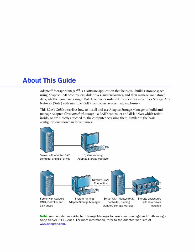
About This GuideAdaptec® Storage ManagerTM is a software application that helps you build a storage space using Adaptec RAID controllers, disk drives, and enclosures, and then manage your stored data, whether you have a single RAID controller installed in a server or a complex Storage Area Network (SAN) with multiple RAID controllers, servers, and enclosures.
This User’s Guide describes how to install and use Adaptec Storage Manager to build and manage Adaptec direct attached storage—a RAID controller and disk drives which reside inside, or are directly attached to, the computer accessing them, similar to the basic configurations shown in these figures:
Note: You can also use Adaptec Storage Manager to create and manage an IP SAN using a Snap Server 700i Series. For more information, refer to the Adaptec Web site at www.adaptec.com.
Server with Adaptec RAID controller and disk drives
System running Adaptec Storage Manager
System running Adaptec Storage Manager
Server with AdaptecRAID controller and disk drives
Server with Adaptec RAID controller, running
Adaptec Storage Manager
Storage enclosureswith disk drives
installed
Network (SAN) Connection
● 11
How This Guide is OrganizedThis User’s Guide is divided into three sections:
● Part I: Getting Started—Follow the instructions in this section to install Adaptec Storage Manager and build your storage space. (For a definition of ‘storage space’ and other terms used in this User’s Guide, see page 11.)
● Part II: Using Adaptec Storage Manager—Once your storage space is built, refer to this section for help protecting, modifying, monitoring, and troubleshooting your storage space and its components.
● Part III: Quick Reference—Refer to this section for quick answers to common questions about Adaptec Storage Manager. A comparison of RAID levels is also included.
What You Need to Know Before You BeginThis User’s Guide is written for advanced computer users who want to create a storage space for their data. Advanced knowledge of storage networks is not required, but you should be familiar with computer hardware, data storage, and DAS and Redundant Array of Independent Disks (RAID) technology.
If you are using Adaptec Storage Manager as part of a complex storage system, such as a SAN, you should be familiar with network administration terminology and tasks, have knowledge of Local Area Network (LAN) and SAN technology, and be familiar with the input/output (I/O) technology—such as Serial ATA (SATA) or Serial Attached SCSI (SAS)—that you are using on your network.
Note: Because this User’s Guide covers multiple Adaptec RAID products, some of the features and functions described may not be available for your controller or enclosure.
Terminology Used in this GuideBecause this User’s Guide provides information that can be used to manage multiple Adaptec RAID products in a variety of configurations from DAS to SAN, the generic term “storage space” is used to refer to the controller(s) and disk drives being managed with Adaptec Storage Manager.
For efficiency, the term “components” or “component” is used when referring generically to the physical and virtual parts of your storage space, such as systems, disk drives, controllers, and logical drives.
Many of the terms and concepts referred to in this User’s Guide are known to computer users by multiple names. In this User’s Guide, this terminology is used:
● Controller (also known as adapter, HBA, board, or card)
● Disk drive (also known as hard disk, hard drive, or hard disk drive)
● Logical drive (also known as logical device)
● System (also known as a server, workstation, or computer)
● Enclosure (also known as a JBOD, storage enclosure, or disk enclosure)
Note: For more terminology information, see the Glossary on page 168.

In this part:
Introduction to Adaptec Sto
Installing Adaptec Storage
Building Your Storage Spac
Part I:
Getting Startedrage Manager ..................... 13
Manager ............................. 18
e........................................ 25
1
Introduction to Adaptec Storage ManagerIn this chapter...
Getting Started Checklist ....................................................................................................... 14
About Adaptec Storage Manager ........................................................................................... 14
About the Adaptec Storage Manager Agent .......................................................................... 14
Growing Your Storage Space with Adaptec Storage Manager.............................................. 15
System Requirements ............................................................................................................. 17
Controller Support................................................................................................................. 17
This chapter describes Adaptec Storage Manager and the Adaptec Storage Manager Agent, explains the concept of a “storage space” and provides a checklist of getting-started tasks.

Chapter 1: Introduction to Adaptec Storage Manager ● 14
Getting Started ChecklistPart I of this User’s Guide includes three special Getting Started chapters to help you install, start, and begin to use Adaptec Storage Manager.
Step 1: Familiarize yourself with Adaptec Storage Manager and the Adaptec Storage
Manager Agent (see the remainder of this chapter).
Step 2: Install Adaptec Storage Manager on every system that will be part of your storage
spaces (see page 18).
Step 3: Build your storage space (see page 25).
About Adaptec Storage ManagerAdaptec Storage Manager is a software application that helps you build a storage space for your online data, using Adaptec RAID controllers, disk drives, and enclosures.
Note: For information about creating an IP SAN with Adaptec Storage Manager and the Snap Server 700i Series, refer to the Adaptec Web site at www.adaptec.com.
With Adaptec Storage Manager, you can group disk drives into logical drives and build in redundancy to protect your data and improve system performance. You can also use Adaptec Storage Manager to monitor and maintain all the controllers, enclosures, and disk drives in your storage space from a single location.
About the Adaptec Storage Manager AgentWhen Adaptec Storage Manager is installed on a system, the Adaptec Storage Manager Agent is also installed automatically. The Agent is like a service that keeps your storage space running. It’s designed to run in the background, without user intervention, and its job is to monitor and manage system health, event notifications, tasks schedules, and other on-going processes on that system. It sends notices when tasks are completed successfully, and sounds an alarm when errors or failures occur on that system.
The Agent uses less memory than the full application. If your storage space includes systems that won’t be connected to monitors (and therefore won’t require the user interface described in this User’s Guide), you can choose to run the Agent only on those systems instead of the full application (see page 14). You may want to do this if system resources are limited, or if you want more system resources available for other tasks.
Note: Linux or Unix users only—If your storage space includes systems without X-Windows installed or running, you can run the Agent, even though you can’t run the full Adaptec Storage Manager application.
You can manage and monitor systems running the Agent only by logging into them as remote systems (see page 31).
You can also customize the Agent settings to suit your storage space requirements.

Chapter 1: Introduction to Adaptec Storage Manager ● 15
Growing Your Storage Space with Adaptec Storage ManagerAs your requirements change, Adaptec Storage Manager grows with your storage space as you add more controllers, more disk drives, more logical drives, and more data protection.
A Simple Storage SpaceThis example shows a simple storage space that might be appropriate in a home office or for a small business. This storage space includes one RAID controller and three disk drives installed in a server. For data protection, the disk drives have been used to build a RAID 5 logical drive.
An Advanced Storage SpaceThis example shows how you can grow your storage space to meet the expanding requirements of your business. On the first server, segments of space from each disk drive have been used to build two RAID 5 logical drives. A second server connected to two 12-disk-drive enclosures has been added. The additional storage space has been used to create two RAID 50 logical drives. The Administrator of this storage space can create and modify logical drives and monitor both controllers, disk drives, and enclosures from a single system, called the local system (see page 26).
RAID 5
Server with RAID Controller and Disk Drives
System running Adaptec Storage Manager
Business andCustomer Data
Local System
RAID 5 System running Adaptec Storage Manager
RAID 5
Accounting and Payroll Data
Personnel DataServer with RAID controller and disk drives
Server with RAIDcontroller, running
Adaptec StorageManager Agent
RAID50
RAID50
Storage enclosures with disk drives installed
Customer Data
Network (SAN) Connection
Local System
Chapter 1: Introduction to Adaptec Storage Manager ● 16
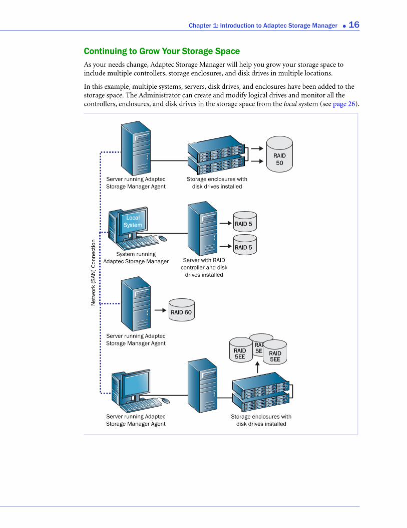
Continuing to Grow Your Storage SpaceAs your needs change, Adaptec Storage Manager will help you grow your storage space to include multiple controllers, storage enclosures, and disk drives in multiple locations.
In this example, multiple systems, servers, disk drives, and enclosures have been added to the storage space. The Administrator can create and modify logical drives and monitor all the controllers, enclosures, and disk drives in the storage space from the local system (see page 26).
RAID50
RAID 60
RAID 5
RAID 5
Server running Adaptec Storage Manager Agent
System running Adaptec Storage Manager
Net
wor
k (S
AN) C
onne
ctio
n
RAID 5EE RAID
5EE
RAI5E
Storage enclosures with disk drives installed
Storage enclosures with disk drives installed
Local System
Server running Adaptec Storage Manager Agent
Server running Adaptec Storage Manager Agent
Server with RAIDcontroller and disk
drives installed

Chapter 1: Introduction to Adaptec Storage Manager ● 17
System RequirementsTo install Adaptec Storage Manager and create a direct attached storage space, each system in your storage space must meet these requirements:
● PC-compatible computer with Intel Pentium 1.2 GHz processor, or equivalent
● At least 256 MB of RAM
● 80 MB of free disk drive space
● 256-color video mode
● CD drive
● One of these operating systems:
● Microsoft® Windows® Server 2008, Windows VistaTM, Windows Server 2003 (Enterprise, Standard, Web Edition 32-bit or 64-bit with current service pack), or Windows XP Professional 32-bit or 64-bit
● Red Hat® Linux
● SUSE Linux
Note: For the latest on Adaptec’s support of Linux, or to download driver sources, visitwww.adaptec.com.
● SCO® OpenServer® 6.0
● SCO UnixWare® 7.1.4
● FreeBSD® 6.2, 6.3
● Sun Solaris 10 with current update
● VMWare® ESX Server 3.0.2, 3.5
Note: Adaptec Storage Manager can also be used before an operating system is installed. See Running Adaptec Storage Manager from the CD on page 23 for more information.
Controller SupportThe maximum number of controllers supported by Adaptec Storage Manager for each supported operating system is:
● Windows—Up to 16 Adaptec controllers
● Linux—Up to 16 Adaptec controllers
● UnixWare—Up to 16 Adaptec controllers
● OpenServer—Up to 16 Adaptec controllers
● Solaris—Up to 16 Adaptec controllers
● FreeBSD—Up to 16 Adaptec controllers
● VMWare—Up to 16 Adaptec controllers
Note: For the most recent operating system support information, visit www.adaptec.com.
2
Installing Adaptec Storage ManagerIn this chapter...Installing on Windows ........................................................................................................... 19
Installing on Linux ................................................................................................................. 20
Installing on UnixWare or OpenServer................................................................................. 21
Installing on Solaris................................................................................................................ 21
Installing on FreeBSD ............................................................................................................ 22
Installing on VMWare............................................................................................................ 22
Using Adaptec Storage Manager with a Firewall .................................................................. 23
Running Adaptec Storage Manager from the CD................................................................. 23
Adaptec Storage Manager must be installed on every system that will be part of your storage space. This chapter describes how to install Adaptec Storage Manager on different operating systems, and explains how to use Adaptec Storage Manager with a firewall.
Note: To use Adaptec Storage Manager to configure a RAID controller before you install your operating system, see Running Adaptec Storage Manager from the CD on page 23.
Chapter 2: Installing Adaptec Storage Manager ● 19
Installing on WindowsThis section describes how to install Adaptec Storage Manager on systems running Windows. See System Requirements on page 17 for a list of supported operating systems.
Note: You need administrator or root privileges to install Adaptec Storage Manager. For details on verifying privileges, refer to your operating system documentation.
If a previous version of Adaptec Storage Manager is installed on your system, you must remove it before beginning this installation. To uninstall Adaptec Storage Manager, use the Add/Remove Programs option in your Windows Control Panel.
Note: Advanced users only—To perform a silent installation, follow the instructions in Appendix A.
To install Adaptec Storage Manager:
1 Insert the Adaptec Storage Manager Installation CD.
The Installation wizard opens automatically. (If it doesn’t open, browse to the CD in Windows Explorer, then click Autorun.)
2 Click Next to begin the installation, click I accept..., then click Next.
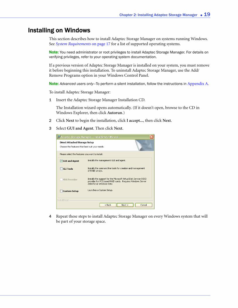
3 Select GUI and Agent. Then click Next.
4 Repeat these steps to install Adaptec Storage Manager on every Windows system that will be part of your storage space.
Chapter 2: Installing Adaptec Storage Manager ● 20
Installing on LinuxThis section describes how to install Adaptec Storage Manager on systems running Linux. See System Requirements on page 17 for a list of supported operating systems.
Adaptec Storage Manager includes the Java Runtime Environment (JRE).
Note: If a previous version of Adaptec Storage Manager is installed on your system, you must remove it before beginning this installation. Any customization files you created with the previous version are saved and used in the upgrade. To remove Adaptec Storage Manager, type the rpm --erase StorMan command.
To install Adaptec Storage Manager:
1 Insert the Adaptec Storage Manager Installation CD.
2 Mount the Adaptec Storage Manager Installation CD:
For Red Hat mount /dev/cdrom /mnt/cdrom
For SUSE mount /dev/cdrom /media/cdrom
3 Change to the cdrom directory:
For Red Hat cd /mnt/cdrom/linux/manager
For SUSE cd /media/cdrom/linux/manager
4 Extract the RPM package and install it:
rpm --install ./StorMan*.rpm
5 Unmount the Adaptec Storage Manager Installation CD:
For Red Hat umount /mnt/cdrom
For SUSE umount /media/cdrom
6 Repeat these Steps to install Adaptec Storage Manager on every Linux system that will be part of your storage space.
Chapter 2: Installing Adaptec Storage Manager ● 21
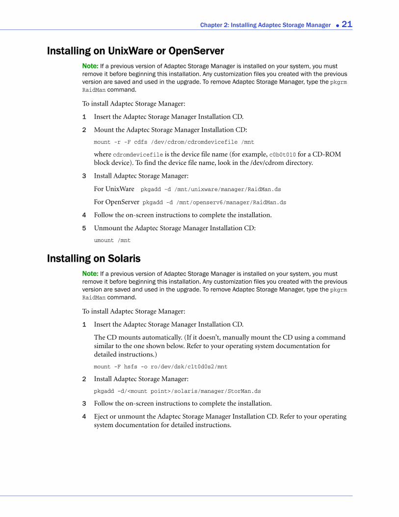
Installing on UnixWare or OpenServerNote: If a previous version of Adaptec Storage Manager is installed on your system, you must remove it before beginning this installation. Any customization files you created with the previous version are saved and used in the upgrade. To remove Adaptec Storage Manager, type the pkgrm RaidMan command.
To install Adaptec Storage Manager:
1 Insert the Adaptec Storage Manager Installation CD.
2 Mount the Adaptec Storage Manager Installation CD:
mount -r -F cdfs /dev/cdrom/cdromdevicefile /mnt
where cdromdevicefile is the device file name (for example, c0b0t010 for a CD-ROM block device). To find the device file name, look in the /dev/cdrom directory.
3 Install Adaptec Storage Manager:
For UnixWare pkgadd -d /mnt/unixware/manager/RaidMan.ds
For OpenServer pkgadd -d /mnt/openserv6/manager/RaidMan.ds
4 Follow the on-screen instructions to complete the installation.
5 Unmount the Adaptec Storage Manager Installation CD:
umount /mnt
Installing on SolarisNote: If a previous version of Adaptec Storage Manager is installed on your system, you must remove it before beginning this installation. Any customization files you created with the previous version are saved and used in the upgrade. To remove Adaptec Storage Manager, type the pkgrm RaidMan command.
To install Adaptec Storage Manager:
1 Insert the Adaptec Storage Manager Installation CD.
The CD mounts automatically. (If it doesn’t, manually mount the CD using a command similar to the one shown below. Refer to your operating system documentation for detailed instructions.)
mount -F hsfs -o ro/dev/dsk/c1t0d0s2/mnt
2 Install Adaptec Storage Manager:
pkgadd -d/<mount point>/solaris/manager/StorMan.ds
3 Follow the on-screen instructions to complete the installation.
4 Eject or unmount the Adaptec Storage Manager Installation CD. Refer to your operating system documentation for detailed instructions.
Chapter 2: Installing Adaptec Storage Manager ● 22
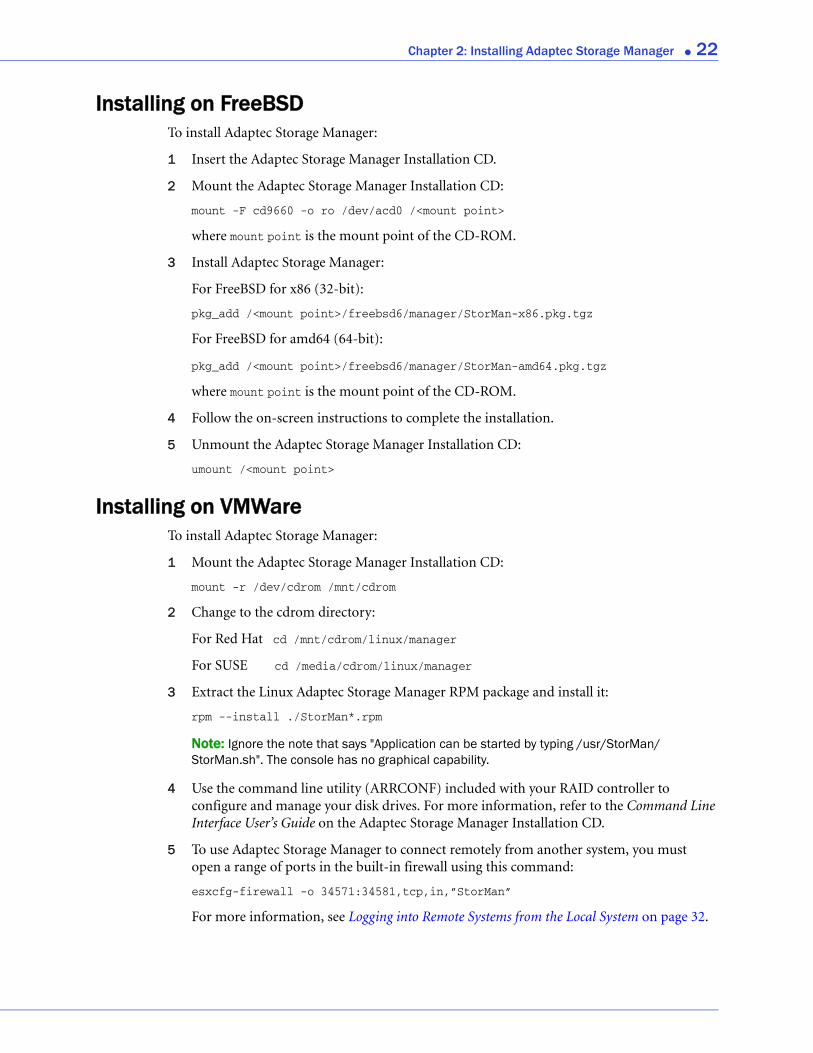
Installing on FreeBSDTo install Adaptec Storage Manager:
1 Insert the Adaptec Storage Manager Installation CD.
2 Mount the Adaptec Storage Manager Installation CD:
mount -F cd9660 -o ro /dev/acd0 /<mount point>
where mount point is the mount point of the CD-ROM.
3 Install Adaptec Storage Manager:
For FreeBSD for x86 (32-bit):
pkg_add /<mount point>/freebsd6/manager/StorMan-x86.pkg.tgz
For FreeBSD for amd64 (64-bit):
pkg_add /<mount point>/freebsd6/manager/StorMan-amd64.pkg.tgz
where mount point is the mount point of the CD-ROM.
4 Follow the on-screen instructions to complete the installation.
5 Unmount the Adaptec Storage Manager Installation CD:
umount /<mount point>
Installing on VMWareTo install Adaptec Storage Manager:
1 Mount the Adaptec Storage Manager Installation CD:
mount -r /dev/cdrom /mnt/cdrom
2 Change to the cdrom directory:
For Red Hat cd /mnt/cdrom/linux/manager
For SUSE cd /media/cdrom/linux/manager
3 Extract the Linux Adaptec Storage Manager RPM package and install it:
rpm --install ./StorMan*.rpm
Note: Ignore the note that says "Application can be started by typing /usr/StorMan/StorMan.sh". The console has no graphical capability.
4 Use the command line utility (ARRCONF) included with your RAID controller to configure and manage your disk drives. For more information, refer to the Command Line Interface User’s Guide on the Adaptec Storage Manager Installation CD.
5 To use Adaptec Storage Manager to connect remotely from another system, you must open a range of ports in the built-in firewall using this command:
esxcfg-firewall -o 34571:34581,tcp,in,”StorMan”
For more information, see Logging into Remote Systems from the Local System on page 32.
Chapter 2: Installing Adaptec Storage Manager ● 23
Using Adaptec Storage Manager with a FirewallIf your system or network includes a firewall, you must unblock these ports:
● 8003 (TCP)
● 34580 (TCP)
● 34570 to 34579 (TCP)
● 34570 (UDP)
● 34577 to 34580 (UDP)
If you have installed the GUI and Agent on a system running Windows XP, you must also unblock the javaw process in the Windows firewall. Refer to your operating system documentation for instructions.
Running Adaptec Storage Manager from the CDThis section describes how to run Adaptec Storage Manager from the Adaptec RAID installation CD included in the kit, instead of as an installed application. When you run Adaptec Storage Manager from the CD, you are using bootable-CD mode.
When to Choose Bootable-CD ModeUse Adaptec Storage Manager in bootable-CD mode if you want to install your operating system on a disk drive or logical drive associated with your controller. Bootable-CD mode lets you configure the controller before you install your operating system.
After you have configured the controller and installed the operating system, install and run Adaptec Storage Manager as an installed software application, as described earlier in this chapter.
Bootable-CD Mode Limitations
Running Adaptec Storage Manager from the CD is not an alternative to running it as an installed software application. Most of the features and functions described in this User’s Guide are not available when you are running Adaptec Storage Manager from the CD. Bootable-CD mode is only for configuring your controller before you install an operating system.
Getting Started in Bootable-CD ModeThis is a checklist of tasks to complete when you’re building your storage space with Adaptec Storage Manager in bootable-CD mode.
Install your Adaptec RAID controller.
Run Adaptec Storage Manager (see the following section).
Create logical drives (see page 34).
For an introduction to the Adaptec Storage Manager window and its features, see page 43.
Install your operating system (and controller device drivers, if appropriate).
Chapter 2: Installing Adaptec Storage Manager ● 24
Install Adaptec Storage Manager as a software application, as described earlier in this
chapter.
Continue to build, customize, and manage your storage space as described in the rest of
this User’s Guide.
Running Adaptec Storage Manager from the CDNote: Before you begin, ensure that your system is set up to boot from a CD. Check the system BIOS to see if the CD drive is listed first in the boot order. For more information, refer to your system’s documentation.
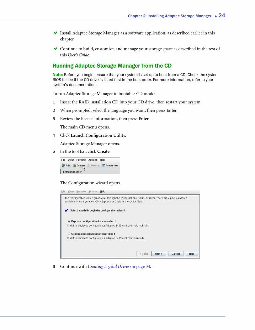
To run Adaptec Storage Manager in bootable-CD mode:
1 Insert the RAID installation CD into your CD drive, then restart your system.
2 When prompted, select the language you want, then press Enter.
3 Review the license information, then press Enter.
The main CD menu opens.
4 Click Launch Configuration Utility.
Adaptec Storage Manager opens.
5 In the tool bar, click Create.
The Configuration wizard opens.
6 Continue with Creating Logical Drives on page 34.
3
Building Your Storage SpaceIn this chapter...Overview................................................................................................................................. 26
Choosing a Management System........................................................................................... 26
Starting and Logging In on the Local System ....................................................................... 27
Starting Adaptec Storage Manager on Remote Systems....................................................... 31
Logging into Remote Systems from the Local System.......................................................... 32
Creating Logical Drives.......................................................................................................... 34
Managing Your Storage Space ............................................................................................... 41
Follow the instructions in this chapter to start Adaptec Storage Manager, log in to each system in your storage space, and create logical drives. (For more information, see Understanding Logical Drives on page 61.)
Note: Before beginning the tasks in this chapter, ensure that Adaptec Storage Manager is installed on every system that will be part of your storage space.
Chapter 3: Building Your Storage Space ● 26
OverviewTo build your storage space, complete these steps as described in the rest of this chapter:
1 Choose at least one management system (see the next section).
2 Start and log in to Adaptec Storage Manager on the management system (see page 27).
3 Start Adaptec Storage Manager or the Agent on all other systems (see page 31).
4 Log in to all other systems from the management system (see page 32).
5 Create logical drives for all systems in your storage space (see page 34).
Choosing a Management SystemYou must designate at least one system as a ‘management system’, a system from which you will manage the direct attached storage on all systems in your storage space.
The management system can be any system on your LAN that has a monitor and can run the full Adaptec Storage Manager application.
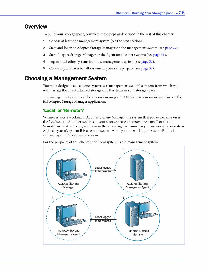
‘Local’ or ‘Remote’?Whenever you’re working in Adaptec Storage Manager, the system that you’re working on is the local system. All other systems in your storage space are remote systems. ‘Local’ and ‘remote’ are relative terms, as shown in the following figure—when you are working on system A (local system), system B is a remote system; when you are working on system B (local system), system A is a remote system.
For the purposes of this chapter, the ‘local system’ is the management system.
A
A B
B
Adaptec Storage Manager
Adaptec Storage Manager or Agent
Adaptec Storage Manager or Agent
Adaptec Storage Manager
Local logged in to remote
Local logged in to remote
Chapter 3: Building Your Storage Space ● 27
Starting and Logging In on the Local SystemThis section describes how to start and log in to the full Adaptec Storage Manager application. It also explains how Adaptec Storage Manager uses existing operating system permission levels to grant different amounts of access to your storage space.
Understanding Permission LevelsWhen you log in to Adaptec Storage Manager, your permission level is identical to your operating system permission level. For example, if you have Administrator permissions on your operating system, you also have Administrator permissions in Adaptec Storage Manager.
This section describes the three different permission levels.
Administrator Level
Logging in as an Administrator allows you full access to manage and modify the controllers, disk drives, and logical drives that are part of your storage space.
To log in as an Administrator:
● Windows—Enter a valid user name and password for the Administrator or Administrative User on the system. (The Administrative User is any member of the local Administrators group, which can, in a Domain configuration, include Domain Administrators.)
● Linux—Enter root for the user name and enter the root password.
● UnixWare or OpenServer—Enter root for the user name and enter the root password.
● Solaris—Enter root for the user name and enter the root password.
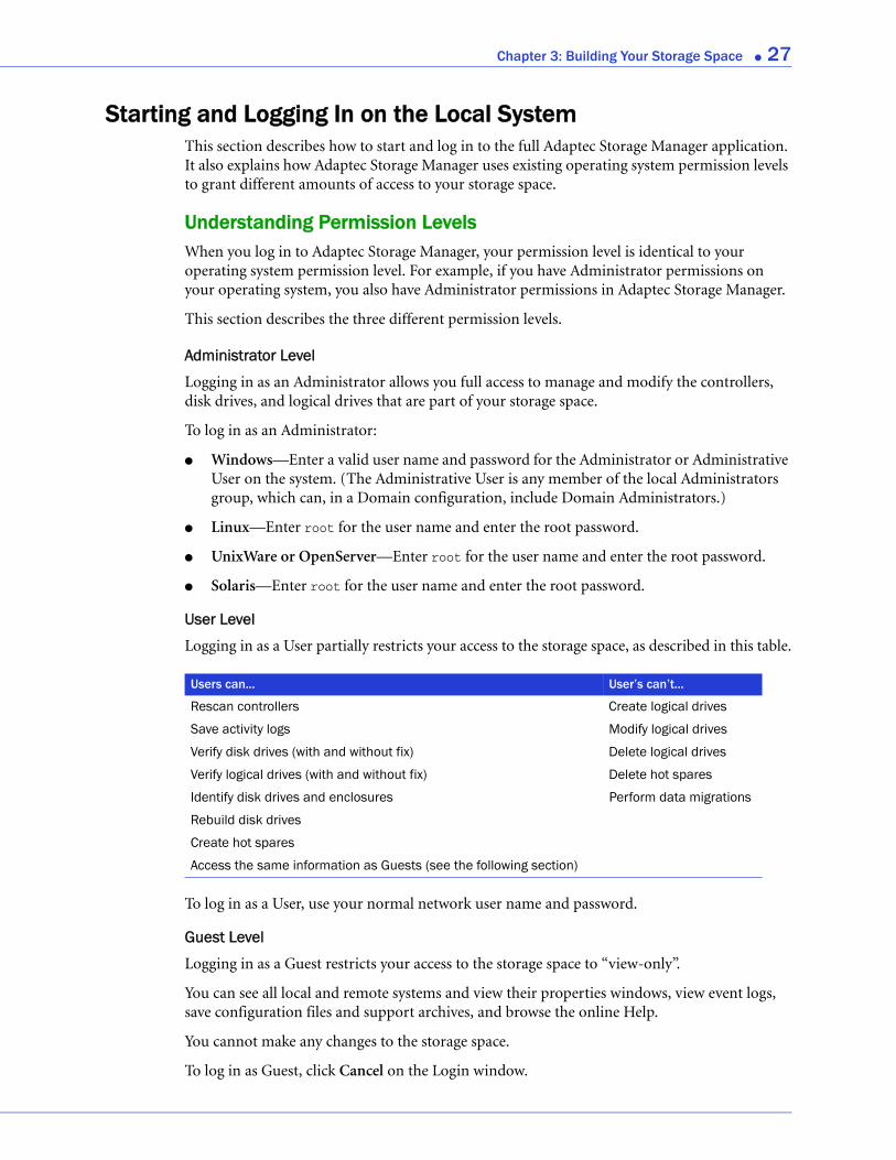
User Level
Logging in as a User partially restricts your access to the storage space, as described in this table.
To log in as a User, use your normal network user name and password.
Guest Level
Logging in as a Guest restricts your access to the storage space to “view-only”.
You can see all local and remote systems and view their properties windows, view event logs, save configuration files and support archives, and browse the online Help.
You cannot make any changes to the storage space.
To log in as Guest, click Cancel on the Login window.
Users can... User’s can’t...
Rescan controllers Create logical drives
Save activity logs Modify logical drives
Verify disk drives (with and without fix) Delete logical drives
Verify logical drives (with and without fix) Delete hot spares
Identify disk drives and enclosures Perform data migrations
Rebuild disk drives
Create hot spares
Access the same information as Guests (see the following section)
Chapter 3: Building Your Storage Space ● 28
Starting and Logging InNote: You need root privileges to run Adaptec Storage Manager.
To start Adaptec Storage Manager and log in on the local system, follow the instructions for your operating system:
● For Windows, see the following section.
● For Linux, see page 29.
● For UnixWare or OpenServer, see page 29.
● For Solaris, see page 29.
● For FreeBSD, see page 29.
Windows
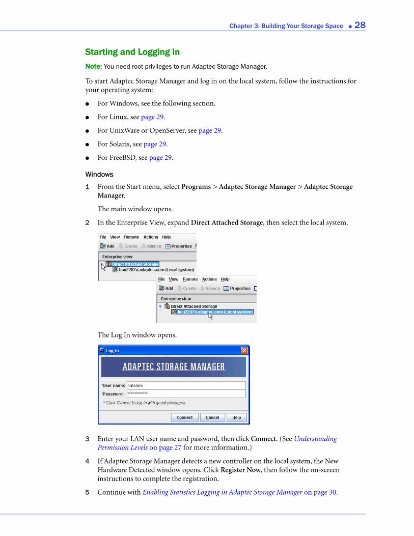
1 From the Start menu, select Programs > Adaptec Storage Manager > Adaptec Storage Manager.
The main window opens.
2 In the Enterprise View, expand Direct Attached Storage, then select the local system.
The Log In window opens.
3 Enter your LAN user name and password, then click Connect. (See Understanding Permission Levels on page 27 for more information.)
4 If Adaptec Storage Manager detects a new controller on the local system, the New Hardware Detected window opens. Click Register Now, then follow the on-screen instructions to complete the registration.
5 Continue with Enabling Statistics Logging in Adaptec Storage Manager on page 30.
Chapter 3: Building Your Storage Space ● 29
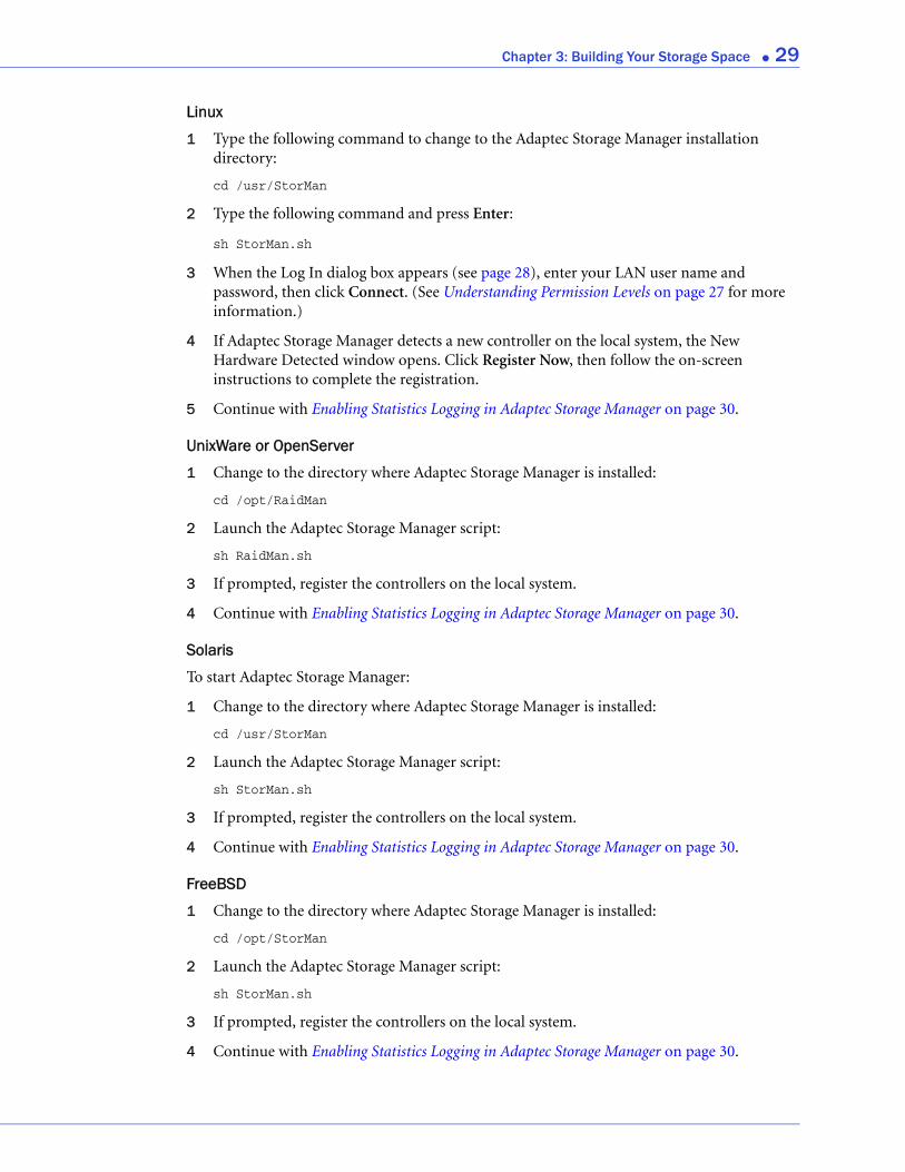
Linux
1 Type the following command to change to the Adaptec Storage Manager installation directory:
cd /usr/StorMan
2 Type the following command and press Enter:
sh StorMan.sh
3 When the Log In dialog box appears (see page 28), enter your LAN user name and password, then click Connect. (See Understanding Permission Levels on page 27 for more information.)
4 If Adaptec Storage Manager detects a new controller on the local system, the New Hardware Detected window opens. Click Register Now, then follow the on-screen instructions to complete the registration.
5 Continue with Enabling Statistics Logging in Adaptec Storage Manager on page 30.
UnixWare or OpenServer
1 Change to the directory where Adaptec Storage Manager is installed:
cd /opt/RaidMan
2 Launch the Adaptec Storage Manager script:
sh RaidMan.sh
3 If prompted, register the controllers on the local system.
4 Continue with Enabling Statistics Logging in Adaptec Storage Manager on page 30.
Solaris
To start Adaptec Storage Manager:
1 Change to the directory where Adaptec Storage Manager is installed:
cd /usr/StorMan
2 Launch the Adaptec Storage Manager script:
sh StorMan.sh
3 If prompted, register the controllers on the local system.
4 Continue with Enabling Statistics Logging in Adaptec Storage Manager on page 30.
FreeBSD
1 Change to the directory where Adaptec Storage Manager is installed:
cd /opt/StorMan
2 Launch the Adaptec Storage Manager script:
sh StorMan.sh
3 If prompted, register the controllers on the local system.
4 Continue with Enabling Statistics Logging in Adaptec Storage Manager on page 30.
Chapter 3: Building Your Storage Space ● 30
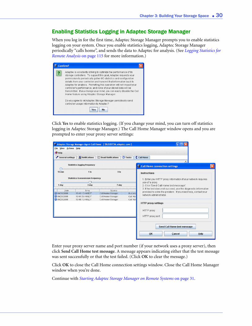
Enabling Statistics Logging in Adaptec Storage ManagerWhen you log in for the first time, Adaptec Storage Manager prompts you to enable statistics logging on your system. Once you enable statistics logging, Adaptec Storage Manager periodically “calls home”, and sends the data to Adaptec for analysis. (See Logging Statistics for Remote Analysis on page 115 for more information.)
Click Yes to enable statistics logging. (If you change your mind, you can turn off statistics logging in Adaptec Storage Manager.) The Call Home Manager window opens and you are prompted to enter your proxy server settings:
Enter your proxy server name and port number (if your network uses a proxy server), then click Send Call Home test message. A message appears indicating either that the test message was sent successfully or that the test failed. (Click OK to clear the message.)
Click OK to close the Call Home connection settings window. Close the Call Home Manager window when you’re done.
Continue with Starting Adaptec Storage Manager on Remote Systems on page 31.
Chapter 3: Building Your Storage Space ● 31
Starting Adaptec Storage Manager on Remote SystemsThe next step is to start Adaptec Storage Manager on all the remote systems in your storage space. (For more information about ‘remote’ systems, see page 26.)
You can run the full application on each system. Alternatively, if your storage space includes systems that aren’t connected to monitors (and therefore won’t require the user interface described in this User’s Guide), you can run the Agent only. You may want to do this if system resources are limited, or if you want more system resources available for other tasks. (For more information, see About the Adaptec Storage Manager Agent on page 14.)
To start:
● The full application, see Starting and Logging In on the Local System on page 27.
● The Agent only, see page 31.
Starting the Full ApplicationTo start the full Adaptec Storage Manager application, follow the instructions in Starting and Logging In on the Local System on page 27.
Starting the Agent OnlyTo start the Adaptec Storage Manager Agent only, follow the instructions for your operating system:
● For Windows, see the following section.
● For Linux or VMWare, see page 31.
● For UnixWare or OpenServer, see page 32.
● For Solaris, see page 32.
Windows
On systems running Windows, the Adaptec Storage Manager Agent starts automatically when the system is powered on.
To verify that the Agent is running:
1 Open the Windows Control Panel.
2 Double-click Administrative Tools, then double-click Services.
3 In the list of services, check that the Adaptec Storage Manager Agent is installed and running. If it’s not, you can choose to restart it.
Linux or VMWare
On systems running Linux or VMWare, the Adaptec Storage Manager Agent starts automatically when the system is powered on.
To verify that the Agent is running:
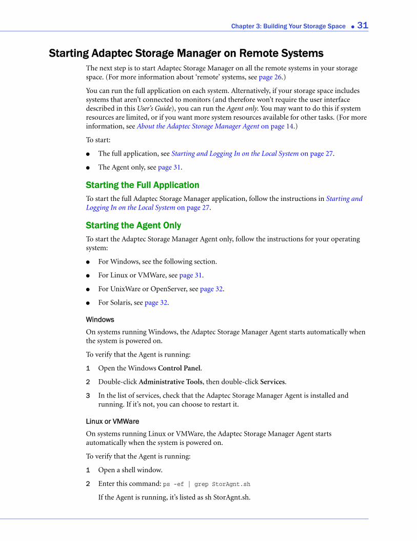
1 Open a shell window.
2 Enter this command: ps -ef | grep StorAgnt.sh
If the Agent is running, it’s listed as sh StorAgnt.sh.
Chapter 3: Building Your Storage Space ● 32
UnixWare or OpenServer
To start the Agent, enter this command:
sh /opt/RaidMan/RaidAgnt.sh
When the Agent has started, a copyright message appears.
Note: To have the Agent run automatically at system start-up, add this line to the /etc/inittab and /etc/conf/init.d/kernel files: nfra:12346:once:sh opt/RaidMan/RaidAgnt.sh
Solaris
To start the Agent, enter this command:
svcadm enable ADPTstor_agent
Logging into Remote Systems from the Local SystemOnce Adaptec Storage Manager or the Adaptec Storage Manager Agent (see page 14) is running on all systems in your storage space, the next step is to log in to the remote systems from the local system.
Once you have logged in to a remote system, it automatically appears in the Enterprise View each time you start Adaptec Storage Manager on the local system. You can work with a remote system’s controllers, disk drives, and logical drives as if they were part of your local system.
Note: Adaptec Storage Manager has a wizard to help you manage the remote systems in your storage space. The wizard simplifies the process of connecting to remote systems and adding them to the Enterprise View. For more information, see Managing Remote Systems on page 123.
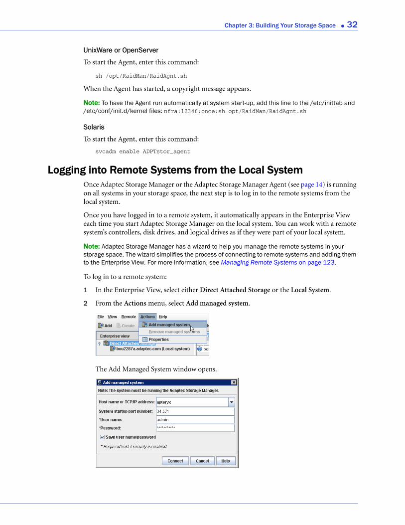
To log in to a remote system:
1 In the Enterprise View, select either Direct Attached Storage or the Local System.
2 From the Actions menu, select Add managed system.
The Add Managed System window opens.
Chapter 3: Building Your Storage Space ● 33
3 Enter the host name or TCP/IP address of the remote system. Or select a system from the drop-down list.
4 Enter the startup port number of the remote system. The default port number is 34571.
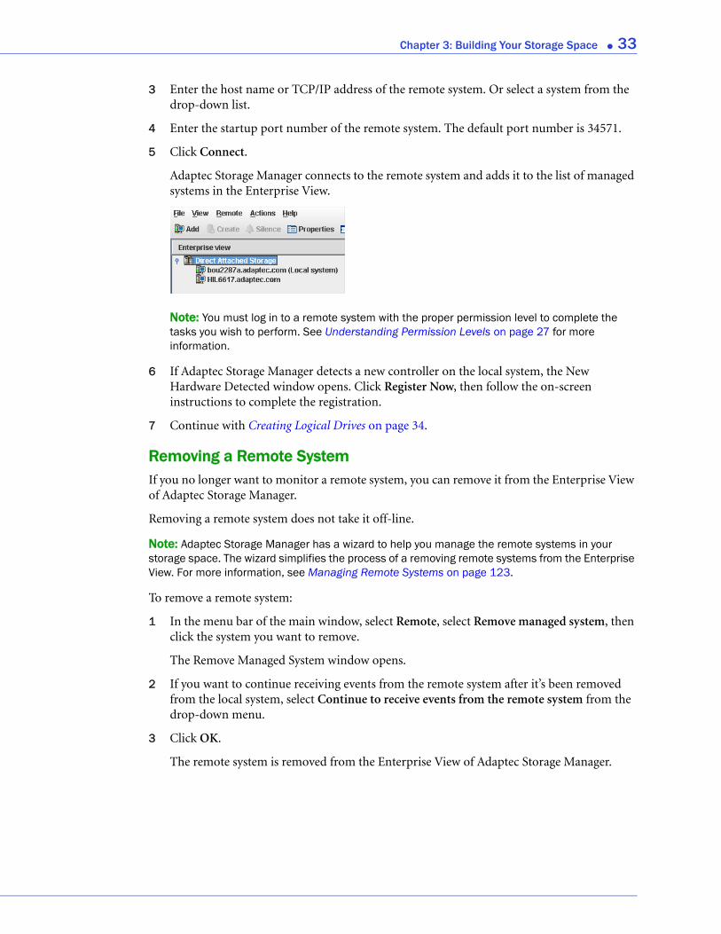
5 Click Connect.
Adaptec Storage Manager connects to the remote system and adds it to the list of managed systems in the Enterprise View.
Note: You must log in to a remote system with the proper permission level to complete the tasks you wish to perform. See Understanding Permission Levels on page 27 for more information.
6 If Adaptec Storage Manager detects a new controller on the local system, the New Hardware Detected window opens. Click Register Now, then follow the on-screen instructions to complete the registration.
7 Continue with Creating Logical Drives on page 34.
Removing a Remote SystemIf you no longer want to monitor a remote system, you can remove it from the Enterprise View of Adaptec Storage Manager.
Removing a remote system does not take it off-line.
Note: Adaptec Storage Manager has a wizard to help you manage the remote systems in your storage space. The wizard simplifies the process of a removing remote systems from the Enterprise View. For more information, see Managing Remote Systems on page 123.
To remove a remote system:
1 In the menu bar of the main window, select Remote, select Remove managed system, then click the system you want to remove.
The Remove Managed System window opens.
2 If you want to continue receiving events from the remote system after it’s been removed from the local system, select Continue to receive events from the remote system from the drop-down menu.
3 Click OK.
The remote system is removed from the Enterprise View of Adaptec Storage Manager.
Chapter 3: Building Your Storage Space ● 34
Creating Logical DrivesAdaptec Storage Manager has a wizard to help you create (or configure) logical drives, and offers two configuration methods to choose from, depending on your needs:
● Express configuration (basic)—Automatically creates logical drives by grouping together same-sized physical drives, and assigns RAID levels based on the number of physical disk drives in the logical drive.
Use the express method when you want to use all available disk drives in the most efficient manner. For instructions, see page 34.
● Custom configuration (advanced)—Helps you group disk drives, set RAID levels, determine logical drive size, and configure advanced settings manually.
Use the custom method when you want to create specific logical drives with any or all available disk drives. For instructions, see page 37.
Note: Adaptec recommends that you not combine SAS and SATA disk drives within the same logical drive. Adaptec Storage Manager generates a warning if you try to create a logical drive using a combination of SAS and SATA disk drives.
Express Configuration: The Easy WayWhen you use express configuration, Adaptec Storage Manager automatically creates logical drives by grouping together same-sized physical disk drives, and assigns RAID levels based on the number of physical disk drives in a logical drive:
● A logical drive with three or more physical disk drives is assigned RAID 5.
● A logical drive with two physical disk drives is assigned RAID 1.
● A logical drive with only a single physical disk drive becomes a simple volume, which does not offer redundancy.
Note: To create a logical drive with any other RAID level, you must use the custom method, as described on page 37. See Selecting the Best RAID Level on page 148 for more information about RAID levels.
By default, logical drive size is set by Adaptec Storage Manager and automatically maximizes the capacity of the disk drives. However, you can choose to specify a size for a logical drive, if required.
To build your storage space with the express method:
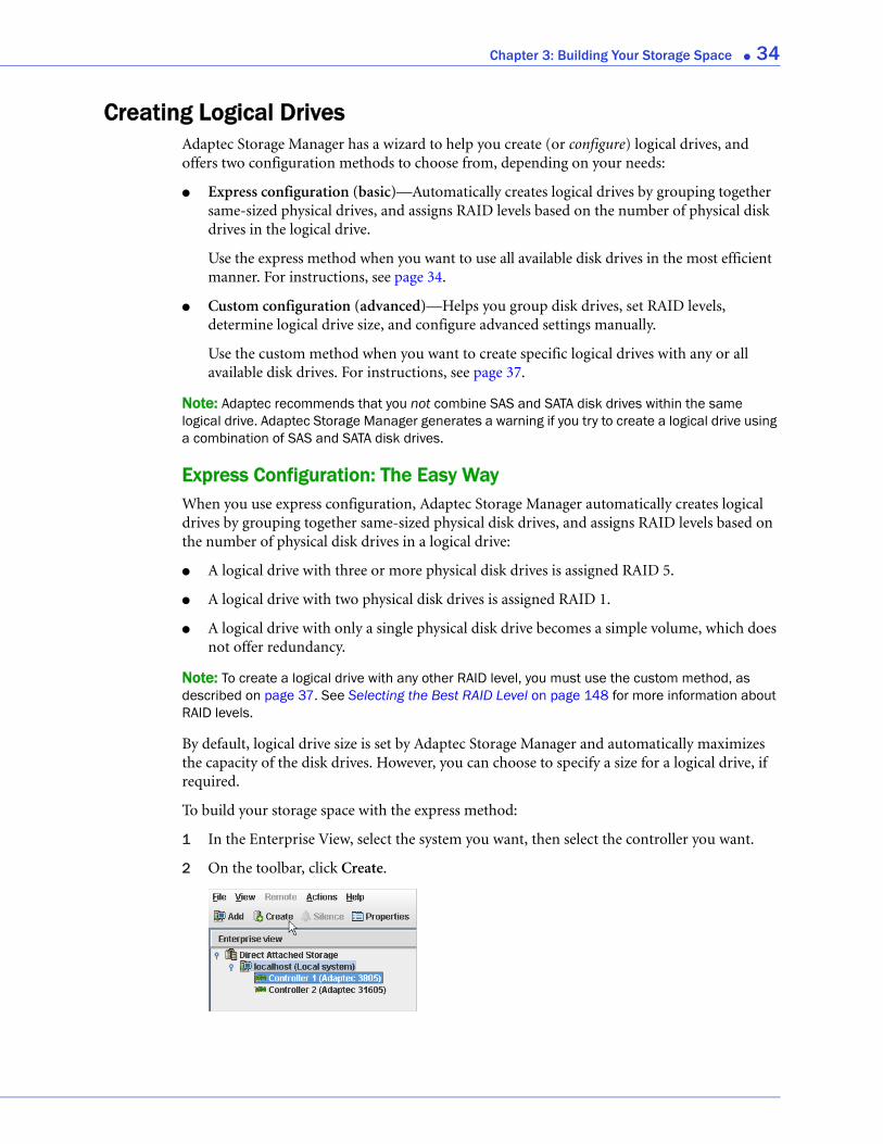
1 In the Enterprise View, select the system you want, then select the controller you want.
2 On the toolbar, click Create.
Chapter 3: Building Your Storage Space ● 35
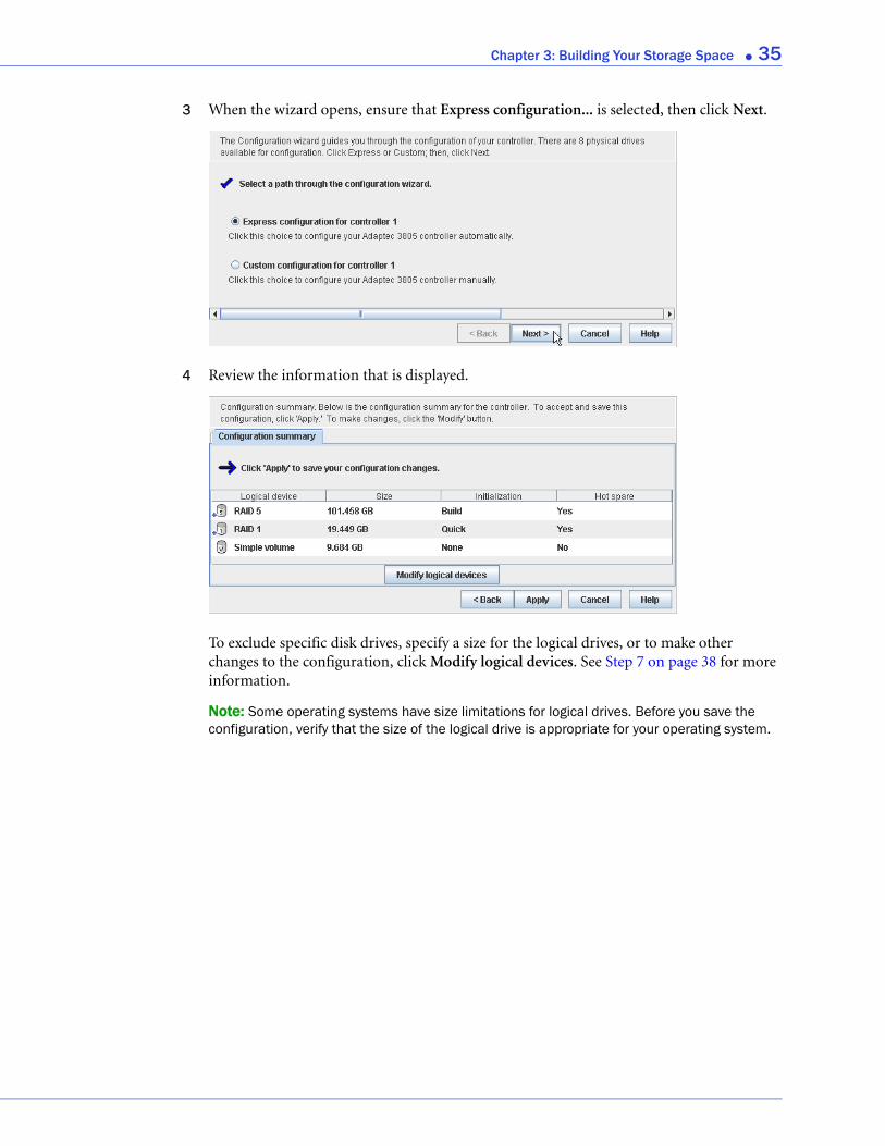
3 When the wizard opens, ensure that Express configuration... is selected, then click Next.
4 Review the information that is displayed.
To exclude specific disk drives, specify a size for the logical drives, or to make other changes to the configuration, click Modify logical devices. See Step 7 on page 38 for more information.
Note: Some operating systems have size limitations for logical drives. Before you save the configuration, verify that the size of the logical drive is appropriate for your operating system.
Chapter 3: Building Your Storage Space ● 36
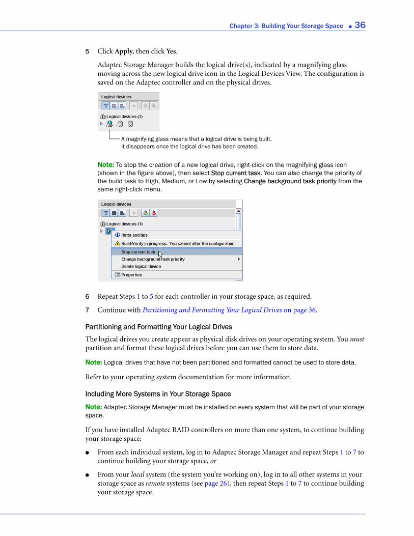
5 Click Apply, then click Yes.
Adaptec Storage Manager builds the logical drive(s), indicated by a magnifying glass moving across the new logical drive icon in the Logical Devices View. The configuration is saved on the Adaptec controller and on the physical drives.
Note: To stop the creation of a new logical drive, right-click on the magnifying glass icon (shown in the figure above), then select Stop current task. You can also change the priority of the build task to High, Medium, or Low by selecting Change background task priority from the same right-click menu.
6 Repeat Steps 1 to 5 for each controller in your storage space, as required.
7 Continue with Partitioning and Formatting Your Logical Drives on page 36.
Partitioning and Formatting Your Logical Drives
The logical drives you create appear as physical disk drives on your operating system. You must partition and format these logical drives before you can use them to store data.
Note: Logical drives that have not been partitioned and formatted cannot be used to store data.
Refer to your operating system documentation for more information.
Including More Systems in Your Storage Space
Note: Adaptec Storage Manager must be installed on every system that will be part of your storage space.
If you have installed Adaptec RAID controllers on more than one system, to continue building your storage space:
● From each individual system, log in to Adaptec Storage Manager and repeat Steps 1 to 7 to continue building your storage space, or
● From your local system (the system you’re working on), log in to all other systems in your storage space as remote systems (see page 26), then repeat Steps 1 to 7 to continue building your storage space.
A magnifying glass means that a logical drive is being built. It disappears once the logical drive has been created.
Chapter 3: Building Your Storage Space ● 37
The maximum number of supported RAID controllers varies depending on your operating system. See Controller Support on page 17 for more information.
To continue, see Managing Your Storage Space on page 41.
Custom Configuration (Advanced)Custom configuration helps you build your storage space manually by stepping you through the process of creating logical drives, setting RAID levels, and configuring other settings.
To build your storage space with custom configuration:
1 In the Enterprise View, select the system you want, then select the controller you want.
Note how many available disk drives are connected to the controller; this information will be helpful as you create logical drives.
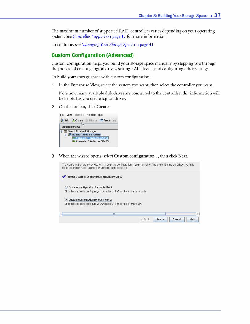
2 On the toolbar, click Create.
3 When the wizard opens, select Custom configuration..., then click Next.
Chapter 3: Building Your Storage Space ● 38
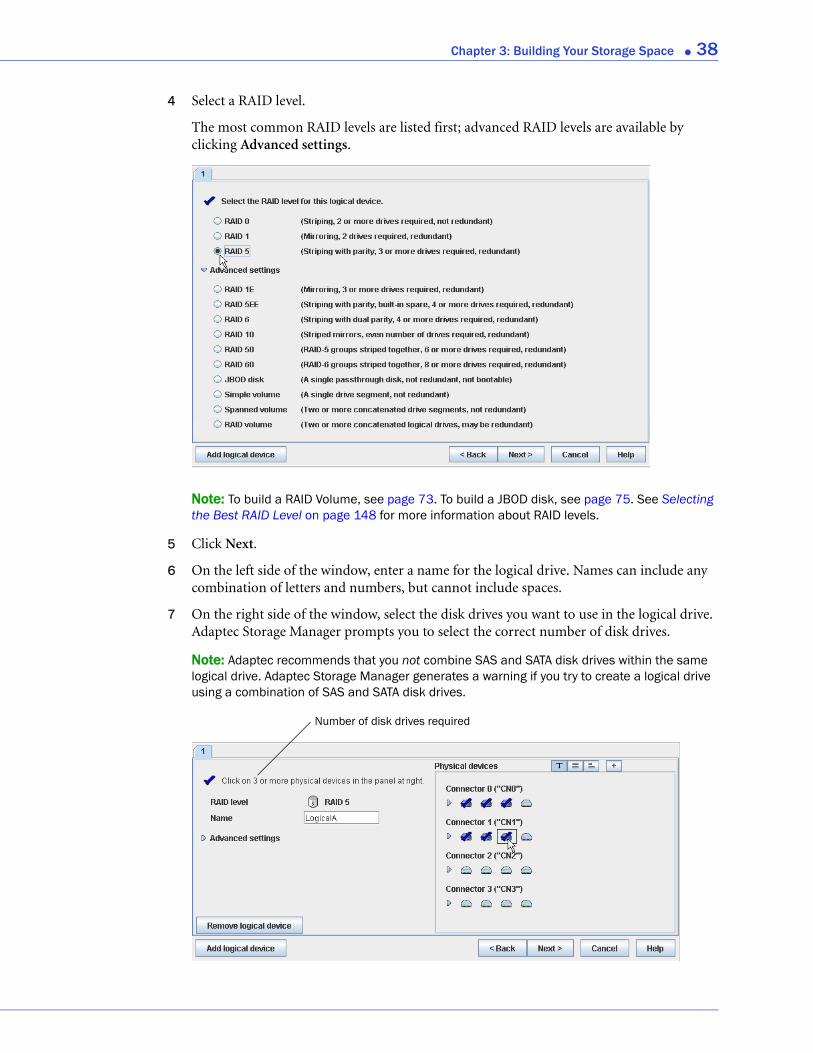
4 Select a RAID level.
The most common RAID levels are listed first; advanced RAID levels are available by clicking Advanced settings.
Note: To build a RAID Volume, see page 73. To build a JBOD disk, see page 75. See Selecting the Best RAID Level on page 148 for more information about RAID levels.
5 Click Next.
6 On the left side of the window, enter a name for the logical drive. Names can include any combination of letters and numbers, but cannot include spaces.
7 On the right side of the window, select the disk drives you want to use in the logical drive. Adaptec Storage Manager prompts you to select the correct number of disk drives.
Note: Adaptec recommends that you not combine SAS and SATA disk drives within the same logical drive. Adaptec Storage Manager generates a warning if you try to create a logical drive using a combination of SAS and SATA disk drives.
Number of disk drives required
Chapter 3: Building Your Storage Space ● 39
By default, Adaptec Storage Manager automatically sets the size of the logical drive and maximizes the capacity of the disk drives you select. (To set a custom size for the logical drive, see Step 9.)
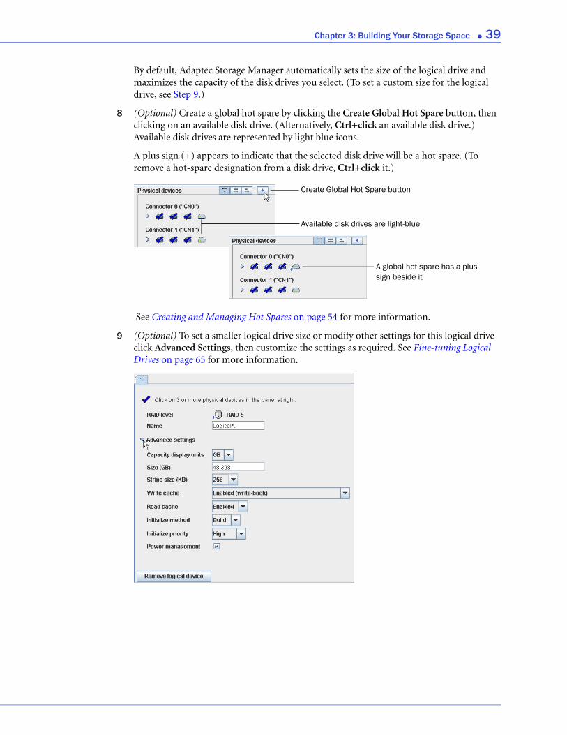
8 (Optional) Create a global hot spare by clicking the Create Global Hot Spare button, then clicking on an available disk drive. (Alternatively, Ctrl+click an available disk drive.) Available disk drives are represented by light blue icons.
A plus sign (+) appears to indicate that the selected disk drive will be a hot spare. (To remove a hot-spare designation from a disk drive, Ctrl+click it.)
See Creating and Managing Hot Spares on page 54 for more information.
9 (Optional) To set a smaller logical drive size or modify other settings for this logical drive click Advanced Settings, then customize the settings as required. See Fine-tuning Logical Drives on page 65 for more information.
Create Global Hot Spare button
A global hot spare has a plus sign beside it
Available disk drives are light-blue

Chapter 3: Building Your Storage Space ● 40
10 If you have no other available disk drives, skip to Step 12.
If you have available disk drives and want to create additional logical drives, click Add logical device to open a new tab in the wizard.
11 Repeat Steps 4 to 10 for each logical drive that you want to create on the controller.
12 Click Next, then review the logical drive settings.
This example shows two logical drives with RAID 5 are ready to be created.
To make changes, click Back.
Note: Some operating systems have size limitations for logical drives. Before continuing, verify that the size of the logical drive is appropriate for your operating system. For more information, refer to your operating system documentation.
13 Click Apply, then click Yes.
Adaptec Storage Manager builds the logical drive(s), indicated by a magnifying glass moving across the new logical drive icon in the Logical Devices View.
The logical drive power management timers window opens.
Tab for second logical drive
A magnifying glass means that a logical drive is being built. It disappears once the logical drive has been created.
Chapter 3: Building Your Storage Space ● 41
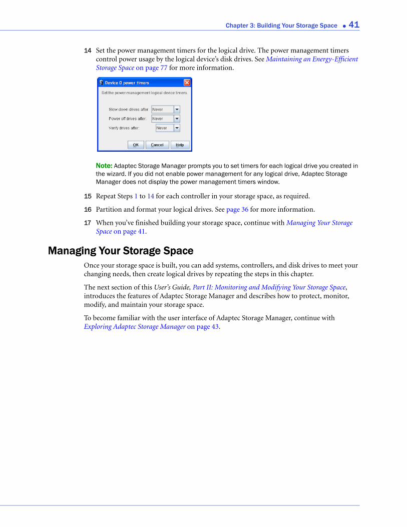
14 Set the power management timers for the logical drive. The power management timers control power usage by the logical device’s disk drives. See Maintaining an Energy-Efficient Storage Space on page 77 for more information.
Note: Adaptec Storage Manager prompts you to set timers for each logical drive you created in the wizard. If you did not enable power management for any logical drive, Adaptec Storage Manager does not display the power management timers window.
15 Repeat Steps 1 to 14 for each controller in your storage space, as required.
16 Partition and format your logical drives. See page 36 for more information.
17 When you’ve finished building your storage space, continue with Managing Your Storage Space on page 41.
Managing Your Storage SpaceOnce your storage space is built, you can add systems, controllers, and disk drives to meet your changing needs, then create logical drives by repeating the steps in this chapter.
The next section of this User’s Guide, Part II: Monitoring and Modifying Your Storage Space, introduces the features of Adaptec Storage Manager and describes how to protect, monitor, modify, and maintain your storage space.
To become familiar with the user interface of Adaptec Storage Manager, continue with Exploring Adaptec Storage Manager on page 43.
In this part:
Exploring Adaptec Stora
Protecting Your Data .....
Modifying Your Direct At
Scheduling Recurring or
Maintaining Physical De
Monitoring Status and A
Updating and Customizi
Solving Problems..........
Part II:
Monitoring and Modifying YourStorage Space
ge Manager ............................. 43
.............................................. 53
tached Storage ........................ 60
Resource-Intensive Jobs .......... 81
vices....................................... 87
ctivity ..................................... 99
ng Adaptec Storage Manager .. 120
............................................ 131
4
Exploring Adaptec Storage ManagerIn this chapter...Working in Adaptec Storage Manager .................................................................................. 44
Overview of the Main Window ............................................................................................. 44
Revealing More Device Information ..................................................................................... 49
Checking System Status from the Main Window................................................................. 50
Getting Help ........................................................................................................................... 50
Logging Out of Adaptec Storage Manager ............................................................................ 51
Uninstalling Adaptec Storage Manager................................................................................. 51
Before you build your storage space, familiarize yourself with the main features of Adaptec Storage Manager and learn to navigate to the information you need.
Chapter 4: Exploring Adaptec Storage Manager ● 44
Working in Adaptec Storage ManagerAdaptec Storage Manager provides multiple ways to work with its menus and windows.
Most menu options are available by:
● Selecting items from the menu bar.
● Clicking buttons on the tool bar.
● Right-clicking on components in the main window. (Only tasks and windows associated with a specific component are available on right-click menus.)
For simplicity, the tasks in this User’s Guide are explained mainly using menu bar options.
About the Actions MenuMost of the main tasks in Adaptec Storage Manager are available from the Actions menu on the menu bar. Options that appear on the Actions menu vary, depending on which type of component is selected in the main window. For instance, managed systems, disk drives, and hot spares each have specialized Actions menus.
For an overview of all Actions menu options, see What options are on the Actions menu? on page 160.
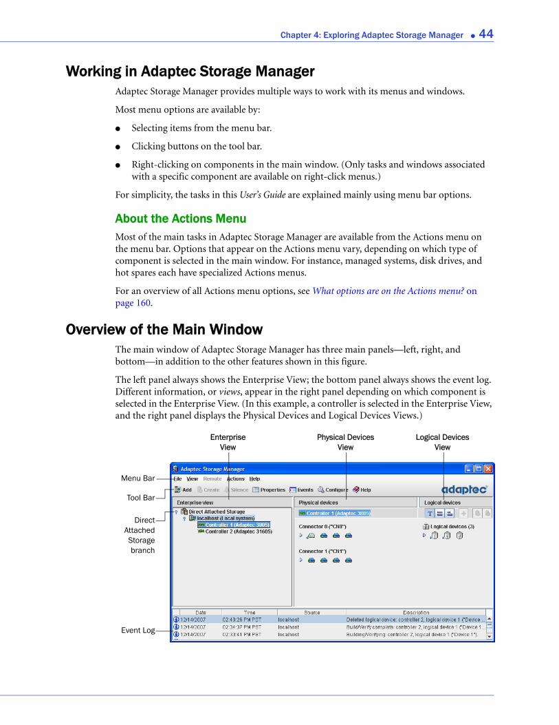
Overview of the Main WindowThe main window of Adaptec Storage Manager has three main panels—left, right, and bottom—in addition to the other features shown in this figure.
The left panel always shows the Enterprise View; the bottom panel always shows the event log. Different information, or views, appear in the right panel depending on which component is selected in the Enterprise View. (In this example, a controller is selected in the Enterprise View, and the right panel displays the Physical Devices and Logical Devices Views.)
Tool Bar
Menu Bar
Physical DevicesView
Logical DevicesView
EnterpriseView
Event Log
DirectAttachedStoragebranch
Chapter 4: Exploring Adaptec Storage Manager ● 45
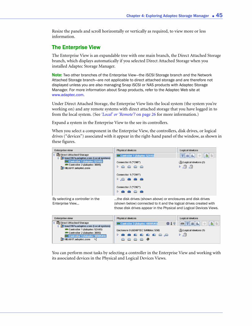
Resize the panels and scroll horizontally or vertically as required, to view more or less information.
The Enterprise View The Enterprise View is an expandable tree with one main branch, the Direct Attached Storage branch, which displays automatically if you selected Direct Attached Storage when you installed Adaptec Storage Manager.
Note: Two other branches of the Enterprise View—the iSCSI Storage branch and the Network Attached Storage branch—are not applicable to direct attached storage and are therefore not displayed unless you are also managing Snap iSCSI or NAS products with Adaptec Storage Manager. For more information about Snap products, refer to the Adaptec Web site at www.adaptec.com.
Under Direct Attached Storage, the Enterprise View lists the local system (the system you’re working on) and any remote systems with direct attached storage that you have logged in to from the local system. (See ‘Local’ or ‘Remote’? on page 26 for more information.)
Expand a system in the Enterprise View to the see its controllers.
When you select a component in the Enterprise View, the controllers, disk drives, or logical drives (“devices”) associated with it appear in the right-hand panel of the window, as shown in these figures.
You can perform most tasks by selecting a controller in the Enterprise View and working with its associated devices in the Physical and Logical Devices Views.
By selecting a controller in the Enterprise View...
...the disk drives (shown above) or enclosures and disk drives (shown below) connected to it and the logical drives created with those disk drives appear in the Physical and Logical Devices Views.
Chapter 4: Exploring Adaptec Storage Manager ● 46
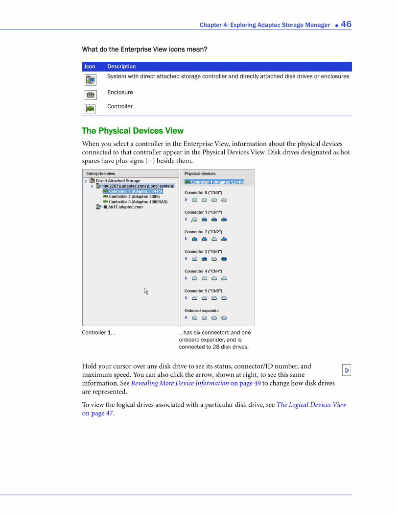
What do the Enterprise View icons mean?
The Physical Devices ViewWhen you select a controller in the Enterprise View, information about the physical devices connected to that controller appear in the Physical Devices View. Disk drives designated as hot spares have plus signs (+) beside them.
Hold your cursor over any disk drive to see its status, connector/ID number, and maximum speed. You can also click the arrow, shown at right, to see this same information. See Revealing More Device Information on page 49 to change how disk drives are represented.
To view the logical drives associated with a particular disk drive, see The Logical Devices View on page 47.
Icon Description
System with direct attached storage controller and directly attached disk drives or enclosures
Enclosure
Controller
...has six connectors and one onboard expander, and is connected to 28 disk drives.
Controller 1...
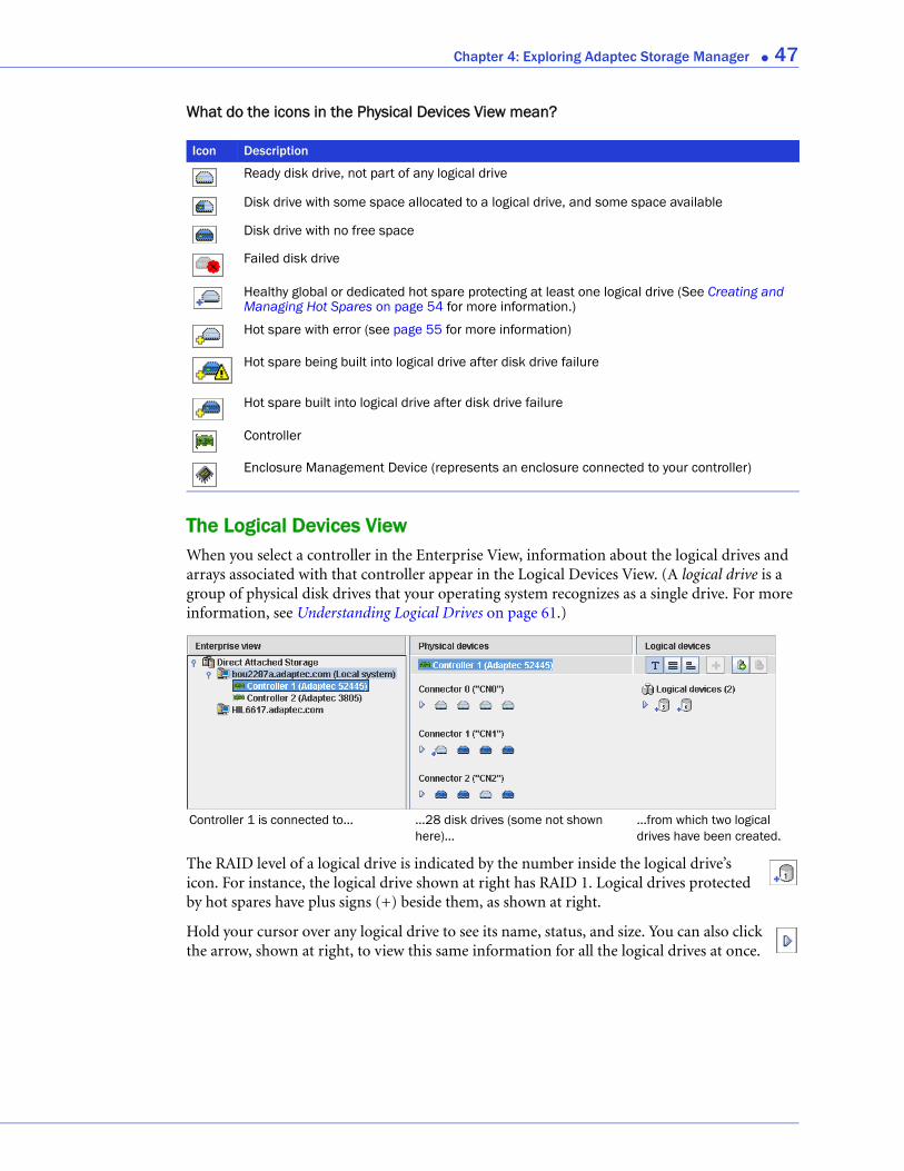
Chapter 4: Exploring Adaptec Storage Manager ● 47
What do the icons in the Physical Devices View mean?
The Logical Devices ViewWhen you select a controller in the Enterprise View, information about the logical drives and arrays associated with that controller appear in the Logical Devices View. (A logical drive is a group of physical disk drives that your operating system recognizes as a single drive. For more information, see Understanding Logical Drives on page 61.)
The RAID level of a logical drive is indicated by the number inside the logical drive’s icon. For instance, the logical drive shown at right has RAID 1. Logical drives protected by hot spares have plus signs (+) beside them, as shown at right.
Hold your cursor over any logical drive to see its name, status, and size. You can also click the arrow, shown at right, to view this same information for all the logical drives at once.
Icon Description
Ready disk drive, not part of any logical drive
Disk drive with some space allocated to a logical drive, and some space available
Disk drive with no free space
Failed disk drive
Healthy global or dedicated hot spare protecting at least one logical drive (See Creating and Managing Hot Spares on page 54 for more information.)
Hot spare with error (see page 55 for more information)
Hot spare being built into logical drive after disk drive failure
Hot spare built into logical drive after disk drive failure
Controller
Enclosure Management Device (represents an enclosure connected to your controller)
...28 disk drives (some not shown here)...
...from which two logical drives have been created.
Controller 1 is connected to...
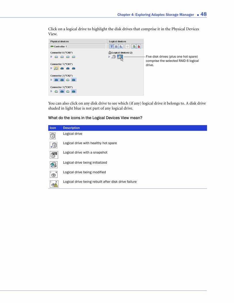
Chapter 4: Exploring Adaptec Storage Manager ● 48
Click on a logical drive to highlight the disk drives that comprise it in the Physical Devices View.
You can also click on any disk drive to see which (if any) logical drive it belongs to. A disk drive shaded in light blue is not part of any logical drive.
What do the icons in the Logical Devices View mean?
Five disk drives (plus one hot spare) comprise the selected RAID 6 logical drive.
Icon Description
Logical drive
Logical drive with healthy hot spare
Logical drive with a snapshot
Logical drive being initialized
Logical drive being modified
Logical drive being rebuilt after disk drive failure
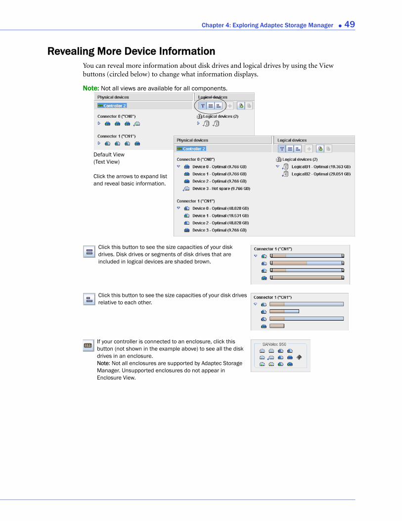
Chapter 4: Exploring Adaptec Storage Manager ● 49
Revealing More Device InformationYou can reveal more information about disk drives and logical drives by using the View buttons (circled below) to change what information displays.
Note: Not all views are available for all components.
Default View (Text View)
Click the arrows to expand list and reveal basic information.
Click this button to see the size capacities of your disk drives. Disk drives or segments of disk drives that are included in logical devices are shaded brown.
Click this button to see the size capacities of your disk drives relative to each other.
If your controller is connected to an enclosure, click this button (not shown in the example above) to see all the disk drives in an enclosure. Note: Not all enclosures are supported by Adaptec Storage Manager. Unsupported enclosures do not appear in Enclosure View.
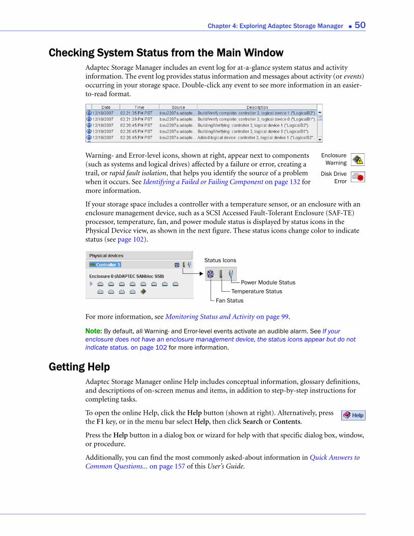
Chapter 4: Exploring Adaptec Storage Manager ● 50
Checking System Status from the Main WindowAdaptec Storage Manager includes an event log for at-a-glance system status and activity information. The event log provides status information and messages about activity (or events) occurring in your storage space. Double-click any event to see more information in an easier-to-read format.
Warning- and Error-level icons, shown at right, appear next to components (such as systems and logical drives) affected by a failure or error, creating a trail, or rapid fault isolation, that helps you identify the source of a problem when it occurs. See Identifying a Failed or Failing Component on page 132 for more information.
If your storage space includes a controller with a temperature sensor, or an enclosure with an enclosure management device, such as a SCSI Accessed Fault-Tolerant Enclosure (SAF-TE) processor, temperature, fan, and power module status is displayed by status icons in the Physical Device view, as shown in the next figure. These status icons change color to indicate status (see page 102).
For more information, see Monitoring Status and Activity on page 99.
Note: By default, all Warning- and Error-level events activate an audible alarm. See If your enclosure does not have an enclosure management device, the status icons appear but do not indicate status. on page 102 for more information.
Getting HelpAdaptec Storage Manager online Help includes conceptual information, glossary definitions, and descriptions of on-screen menus and items, in addition to step-by-step instructions for completing tasks.
To open the online Help, click the Help button (shown at right). Alternatively, press the F1 key, or in the menu bar select Help, then click Search or Contents.
Press the Help button in a dialog box or wizard for help with that specific dialog box, window, or procedure.
Additionally, you can find the most commonly asked-about information in Quick Answers to Common Questions... on page 157 of this User’s Guide.
EnclosureWarning
Disk DriveError
Fan StatusTemperature Status
Power Module Status
Status Icons
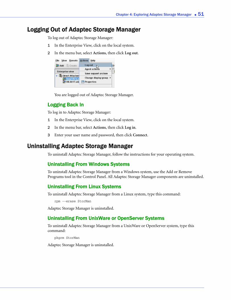
Chapter 4: Exploring Adaptec Storage Manager ● 51
Logging Out of Adaptec Storage ManagerTo log out of Adaptec Storage Manager:
1 In the Enterprise View, click on the local system.
2 In the menu bar, select Actions, then click Log out.
You are logged out of Adaptec Storage Manager.
Logging Back InTo log in to Adaptec Storage Manager:
1 In the Enterprise View, click on the local system.
2 In the menu bar, select Actions, then click Log in.
3 Enter your user name and password, then click Connect.
Uninstalling Adaptec Storage ManagerTo uninstall Adaptec Storage Manager, follow the instructions for your operating system.
Uninstalling From Windows SystemsTo uninstall Adaptec Storage Manager from a Windows system, use the Add or Remove Programs tool in the Control Panel. All Adaptec Storage Manager components are uninstalled.
Uninstalling From Linux SystemsTo uninstall Adaptec Storage Manager from a Linux system, type this command:
rpm --erase StorMan
Adaptec Storage Manager is uninstalled.
Uninstalling From UnixWare or OpenServer SystemsTo uninstall Adaptec Storage Manager from a UnixWare or OpenServer system, type this command:
pkgrm StorMan
Adaptec Storage Manager is uninstalled.
Chapter 4: Exploring Adaptec Storage Manager ● 52
Uninstalling From Solaris Systems
To uninstall Adaptec Storage Manager from a Solaris system, type this command:
pkgrm StorMan
Adaptec Storage Manager is uninstalled.
Uninstalling From FreeBSD SystemsTo uninstall Adaptec Storage Manager from a FreeBSD system, type this command:
pkg_delete Storman-x.x.x-x86 or pkg_delete Storman-x.x.x-amd64
where x.x.x is the package version.
Adaptec Storage Manager is uninstalled.
Uninstalling From VMWare SystemsTo uninstall Adaptec Storage Manager from a VMWare system, type this command:
rpm --erase StorMan
Adaptec Storage Manager is uninstalled.
5
Protecting Your DataIn this chapter...Creating and Managing Hot Spares ...................................................................................... 54
Creating a Snapshot ............................................................................................................... 57
Enabling Copyback ................................................................................................................ 59
In addition to the standard (RAID 0, RAID 1, RAID 5, RAID 10, RAID 50) and enhanced (RAID 1E, RAID 5EE, RAID 6, RAID 60) RAID levels, controllers with the Adaptec Advanced Data Protection Suite include additional methods of protecting the data on your storage space.
This chapter describes how to use hot spares, snapshots, and copyback to protect your stored data.

Chapter 5: Protecting Your Data ● 54
Creating and Managing Hot SparesA hot spare is a disk drive that automatically replaces any failed drive in a logical drive, and can subsequently be used to rebuild that logical drive. (For more information on recovering from a disk drive failure, see page 133.)
Hot Spare Limitations● You can’t create a hot spare for RAID 0 logical drives, simple volumes, or spanned volumes.
● You can’t create a hot spare from a disk drive that is already part of a logical drive.
● You should select a disk drive that is at least as big as the largest disk drive it might replace.
● Adaptec recommends that you not designate a SAS hot spare for a logical drive comprising SATA disk drives, or a SATA hot spare for a logical drive comprising SAS disk drives.
Dedicated Spare or Global Spare?A global hot spare is not assigned to a specific logical drive and will protect any logical drive on the controller (except RAID 0 logical drives). You can designate a global hot spare before or after you build logical drives on a controller; you can also designate a global hot spare while you’re creating a logical drive. To designate a global hot spare, see page 54.
A dedicated hot spare is assigned to one or more specific logical drives and will only protect those logical drives. (A dedicated hot spare that has been assigned to protect more than one logical drive is called a pool spare.) You must create the logical drive before you can assign a dedicated hot spare. To assign a dedicated hot spare or pool hot spare, see page 55.
Designating a Global Hot SpareThis section describes how to designate a global hot spare before or after you build a logical drive.
Note: To designate a global hot spare while you’re creating a logical drive, see Step 7 on page 38.
To designate a global hot spare:
1 In the Enterprise View, click the controller on which you want a global hot spare.
2 In the Physical Devices View, click the disk drive you want to designate as a hot spare. (See Hot Spare Limitations for help selecting a disk drive.)
3 Click the Create global hot-spare drive button.
A plus sign appears beside the selected disk drive, indicating that it’s designated as a hot spare. (A yellow plus sign indicates an error. See What Do the Hot Spare Icons Mean? on page 55 for help solving the problem.) A plus sign also appears beside each existing logical drive.
Any other logical drives created on the controller will automatically be protected by that global hot spare.

Chapter 5: Protecting Your Data ● 55
Assigning a Dedicated Hot Spare or Pool Hot SpareA dedicated hot spare is assigned to one or more specific logical drives. (A dedicated hot spare that has been assigned to protect more than one logical drive is called a pool hot spare.)
Note: You must create the logical drive before you can assign a dedicated hot spare.
To assign a dedicated or pool hot spare:
1 In the Enterprise View, click the controller on which you want a dedicated hot spare.
2 In the Physical Devices View, click the disk drive you want to designate as a hot spare. (See Hot Spare Limitations on page 54 for help selecting a disk drive.)
3 In the menu bar, select Actions, then click Create dedicated hot-spare drive for, then click the name of the logical drive (in this example, Device 1).
A plus sign appears beside the selected disk drive, indicating that it’s designated as a dedicated hot spare. (A yellow plus sign indicates an error. See What Do the Hot Spare Icons Mean? on page 55 for help solving the problem.)
4 To use the same dedicated hot spare to protect another logical drive (create a pool hot spare), repeat Step 2 and Step 3.
What Do the Hot Spare Icons Mean?
Icon Explanation Action
Healthy global or dedicated hot spare No action required.
Error on hot spare:● Hot spare is not assigned to any logical
drives● Create at least one logical drive on the same
controller
● Hot spare is too small to protect the logical drive(s) it’s assigned to
● Designate larger disk drive as hot spare
● Global hot spare was designated before any logical drives were built
● Create at least one logical drive on the same controller
Hot spare has been built into a logical drive after disk drive failure
Designate replacement or other available disk drive as new hot spare; remove ‘hot spare’ designation from disk drive (see Removing or Deleting a Dedicated Hot Spare)
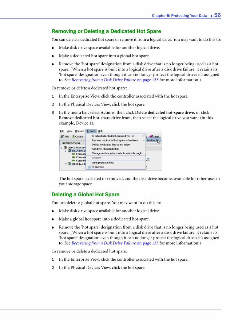
Chapter 5: Protecting Your Data ● 56
Removing or Deleting a Dedicated Hot SpareYou can delete a dedicated hot spare or remove it from a logical drive. You may want to do this to:
● Make disk drive space available for another logical drive.
● Make a dedicated hot spare into a global hot spare.
● Remove the ‘hot spare’ designation from a disk drive that is no longer being used as a hot spare. (When a hot spare is built into a logical drive after a disk drive failure, it retains its ‘hot spare’ designation even though it can no longer protect the logical drives it’s assigned to. See Recovering from a Disk Drive Failure on page 133 for more information.)
To remove or delete a dedicated hot spare:
1 In the Enterprise View, click the controller associated with the hot spare.
2 In the Physical Devices View, click the hot spare.
3 In the menu bar, select Actions, then click Delete dedicated hot-spare drive, or click Remove dedicated hot-spare drive from, then select the logical drive you want (in this example, Device 1).
The hot spare is deleted or removed, and the disk drive becomes available for other uses in your storage space.
Deleting a Global Hot SpareYou can delete a global hot spare. You may want to do this to:
● Make disk drive space available for another logical drive.
● Make a global hot spare into a dedicated hot spare.
● Remove the ‘hot spare’ designation from a disk drive that is no longer being used as a hot spare. (When a hot spare is built into a logical drive after a disk drive failure, it retains its ‘hot spare’ designation even though it can no longer protect the logical drives it’s assigned to. See Recovering from a Disk Drive Failure on page 133 for more information.)
To remove or delete a dedicated hot spare:
1 In the Enterprise View, click the controller associated with the hot spare.
2 In the Physical Devices View, click the hot spare.
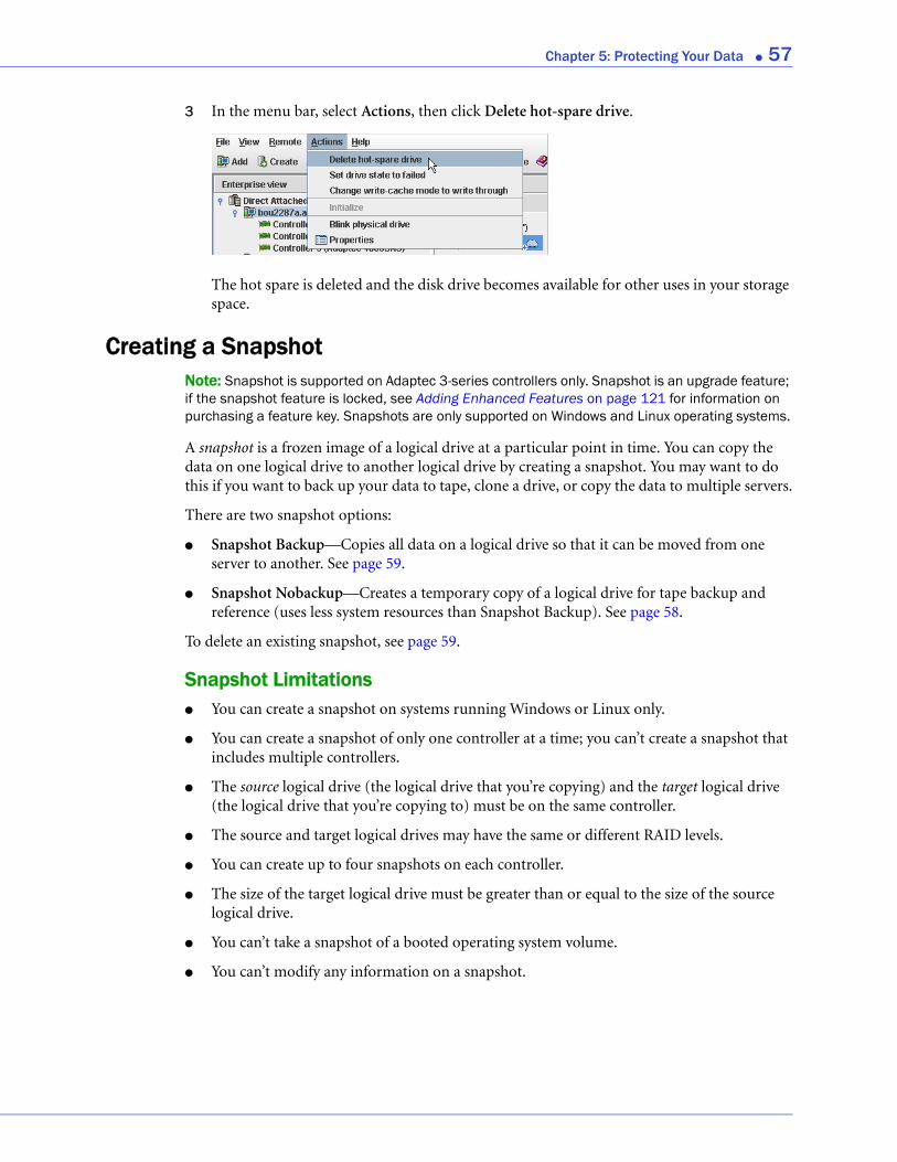
Chapter 5: Protecting Your Data ● 57
3 In the menu bar, select Actions, then click Delete hot-spare drive.
The hot spare is deleted and the disk drive becomes available for other uses in your storage space.
Creating a SnapshotNote: Snapshot is supported on Adaptec 3-series controllers only. Snapshot is an upgrade feature; if the snapshot feature is locked, see Adding Enhanced Features on page 121 for information on purchasing a feature key. Snapshots are only supported on Windows and Linux operating systems.
A snapshot is a frozen image of a logical drive at a particular point in time. You can copy the data on one logical drive to another logical drive by creating a snapshot. You may want to do this if you want to back up your data to tape, clone a drive, or copy the data to multiple servers.
There are two snapshot options:
● Snapshot Backup—Copies all data on a logical drive so that it can be moved from one server to another. See page 59.
● Snapshot Nobackup—Creates a temporary copy of a logical drive for tape backup and reference (uses less system resources than Snapshot Backup). See page 58.
To delete an existing snapshot, see page 59.
Snapshot Limitations● You can create a snapshot on systems running Windows or Linux only.
● You can create a snapshot of only one controller at a time; you can’t create a snapshot that includes multiple controllers.
● The source logical drive (the logical drive that you’re copying) and the target logical drive (the logical drive that you’re copying to) must be on the same controller.
● The source and target logical drives may have the same or different RAID levels.
● You can create up to four snapshots on each controller.
● The size of the target logical drive must be greater than or equal to the size of the source logical drive.
● You can’t take a snapshot of a booted operating system volume.
● You can’t modify any information on a snapshot.

Chapter 5: Protecting Your Data ● 58
Creating a Snapshot With BackupCaution: To avoid a corrupted snapshot, ensure that no files are open or in use on the source logical drive before you begin this task.
To create a snapshot with backup:
1 In the Logical Devices View, right-click the logical drive you want to copy.
2 Click Create snapshot, select with backup to, then click the name of the target logical drive (in this example, “Device1”).
Note: Only logical drives that can support the snapshot are listed.
3 Click Yes to create the snapshot.
The snapshot is created on the target logical drive, which now appears in Adaptec Storage Manager with a camera icon beside it.
!
Target Logical Drive with SnapshotSource Logical Drive
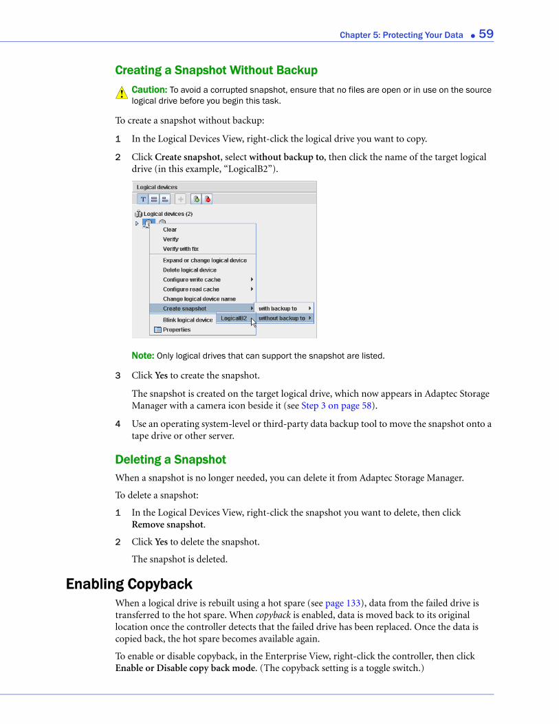
Chapter 5: Protecting Your Data ● 59
Creating a Snapshot Without BackupCaution: To avoid a corrupted snapshot, ensure that no files are open or in use on the source logical drive before you begin this task.
To create a snapshot without backup:
1 In the Logical Devices View, right-click the logical drive you want to copy.
2 Click Create snapshot, select without backup to, then click the name of the target logical drive (in this example, “LogicalB2”).
Note: Only logical drives that can support the snapshot are listed.
3 Click Yes to create the snapshot.
The snapshot is created on the target logical drive, which now appears in Adaptec Storage Manager with a camera icon beside it (see Step 3 on page 58).
4 Use an operating system-level or third-party data backup tool to move the snapshot onto a tape drive or other server.
Deleting a SnapshotWhen a snapshot is no longer needed, you can delete it from Adaptec Storage Manager.
To delete a snapshot:
1 In the Logical Devices View, right-click the snapshot you want to delete, then click Remove snapshot.
2 Click Yes to delete the snapshot.
The snapshot is deleted.
Enabling CopybackWhen a logical drive is rebuilt using a hot spare (see page 133), data from the failed drive is transferred to the hot spare. When copyback is enabled, data is moved back to its original location once the controller detects that the failed drive has been replaced. Once the data is copied back, the hot spare becomes available again.
To enable or disable copyback, in the Enterprise View, right-click the controller, then click Enable or Disable copy back mode. (The copyback setting is a toggle switch.)
!
6
Modifying Your Direct Attached StorageIn this chapter...
Understanding Logical Drives ............................................................................................... 61
Creating and Modifying Logical Drives ................................................................................ 62
Fine-tuning Logical Drives .................................................................................................... 65
Optimizing Logical Drive Performance ................................................................................ 67
Verifying Logical Drives ......................................................................................................... 68
Increasing the Capacity of a Logical Drive............................................................................ 70
Changing the RAID Level of a Logical Drive........................................................................ 72
Deleting a Logical Drive......................................................................................................... 73
Creating a RAID Volume ....................................................................................................... 73
Creating a JBOD Disk ............................................................................................................ 75
Maintaining an Energy-Efficient Storage Space ................................................................... 77
This chapter explains how to create and modify logical drives, optimize logical drive performance, and use Adaptec Storage Manager’s power management features to maintain an energy-efficient storage space.

Chapter 6: Modifying Your Direct Attached Storage ● 61
Understanding Logical DrivesA logical drive is a group of physical disk drives that appears to your operating system as a single drive that can be used for storing data.
A logical drive can comprise one or more disk drives and can use part or all of each disk drive’s capacity.
It is possible to include the same disk drive in two different logical drives by using just a portion of the space on the disk drive in each, as shown in the following figure.
Disk drive space that has been assigned to a logical drive is called a segment. A segment can include all or just a portion of a disk drive’s space. A disk drive with one segment is part of one logical drive, a disk drive with two segments is part of two logical drives, and so on. A segment can be part of only one logical drive. When a logical drive is deleted, the segments that comprised it revert to available space (or free segments).
A logical drive can include redundancy, depending on the RAID level assigned to it. (See Selecting the Best RAID Level on page 148 for more information.)
Once a logical drive has been created, you can change its RAID level or increase its capacity to meet changing requirements. You can also protect your logical drives by assigning one or more hot spares to them. (See page 54 for more information.)
Three Disk Drives (500 MB Each)
One RAID 5 Logical DriveOne RAID 1
Logical Drive
250 MB
250 MB
250 MB
250 MB
250 MB
250 MB 250 MB
250 MB
250 MB250 MB
AvailableSpace
Appears to Operating System as one
250 MB disk drive
Appears to Operating System as one
500 MB disk drive
Chapter 6: Modifying Your Direct Attached Storage ● 62
Creating and Modifying Logical DrivesFor basic instructions for creating logical drives, see Building Your Storage Space on page 25.
This section describes three additional scenarios for creating logical drives, and provides instructions for modifying a logical drive as it’s being created.
● To create a new logical drive of a specified size, see the following section.
● To create a logical drive from different-sized disk drives, see page 63.
● To create a logical drive using available segments of disk drives, see page 64.
● To stop the creation of a new logical drive, see page 64.
● To change the priority of a new logical drive’s creation, see page 64.
Creating a Logical Drive of a Specified SizeAs described in Step 7 on page 38, Adaptec Storage Manager automatically sets the size of a new logical drive to maximize the capacity of the disk drives that it comprises. However, you can choose to set the size for a new logical drive. You may want to do this to maximize your available disk drive space, or allocate available space to more than one logical drive.
To set the size of a logical drive:
1 Complete Steps 1 through 7 in Custom Configuration (Advanced) on page 37.
2 Click Advanced Settings.
The maximum size of the logical drive appears in the Size (GB) box.
3 Enter the new size for the logical drive. The size you enter must be less than or equal to the maximum size.
4 Click Next.
5 Review the logical drive settings, click Apply, then click Yes.
Adaptec Storage Manager builds the logical drive. The configuration is saved in the Adaptec controller and in the physical drives.
If the disk drives you used to create this logical drive have available space left over, you can use them to create a new logical drive (see page 64), or to expand an existing logical drive (see page 70).

Chapter 6: Modifying Your Direct Attached Storage ● 63
Including Different-sized Disk Drives in a Logical DriveYou can combine disk drives of different sizes in the same logical drive. If the logical drive includes redundancy, however, the size of each segment can be no larger than the size of the smallest disk drive. (See Selecting the Best RAID Level on page 148 for more information about redundancy.)
Note: Adaptec recommends that you not combine SAS and SATA disk drives within the same logical drive. Adaptec Storage Manager generates a warning if you try to create a logical drive using a combination of SAS and SATA disk drives.
To create a logical drive with disk drives of different sizes, follow the instructions in Building Your Storage Space on page 25.
When the logical drive is created, it appears similar to the example in the next figure, where a RAID 5 logical drive includes two disk drives of one size and two of another—the disk drive icons indicate that the two larger disk drives still have available space.
The Full Size Capacity View of the same RAID 5 logical drive shows that the larger disk drives still have available space (free segments, indicated in light-blue) that is not part of a logical drive. It also shows that the disk drive designated as a hot spare is large enough to replace any of the disk segments included in the logical drive.
You can include a disk drive’s available space in a new logical drive (see page 64), or add it to an existing logical drive (see page 70).
Disk drive icons showspace still available
Light-blue segments are not part of a logical drive and are still available for use.
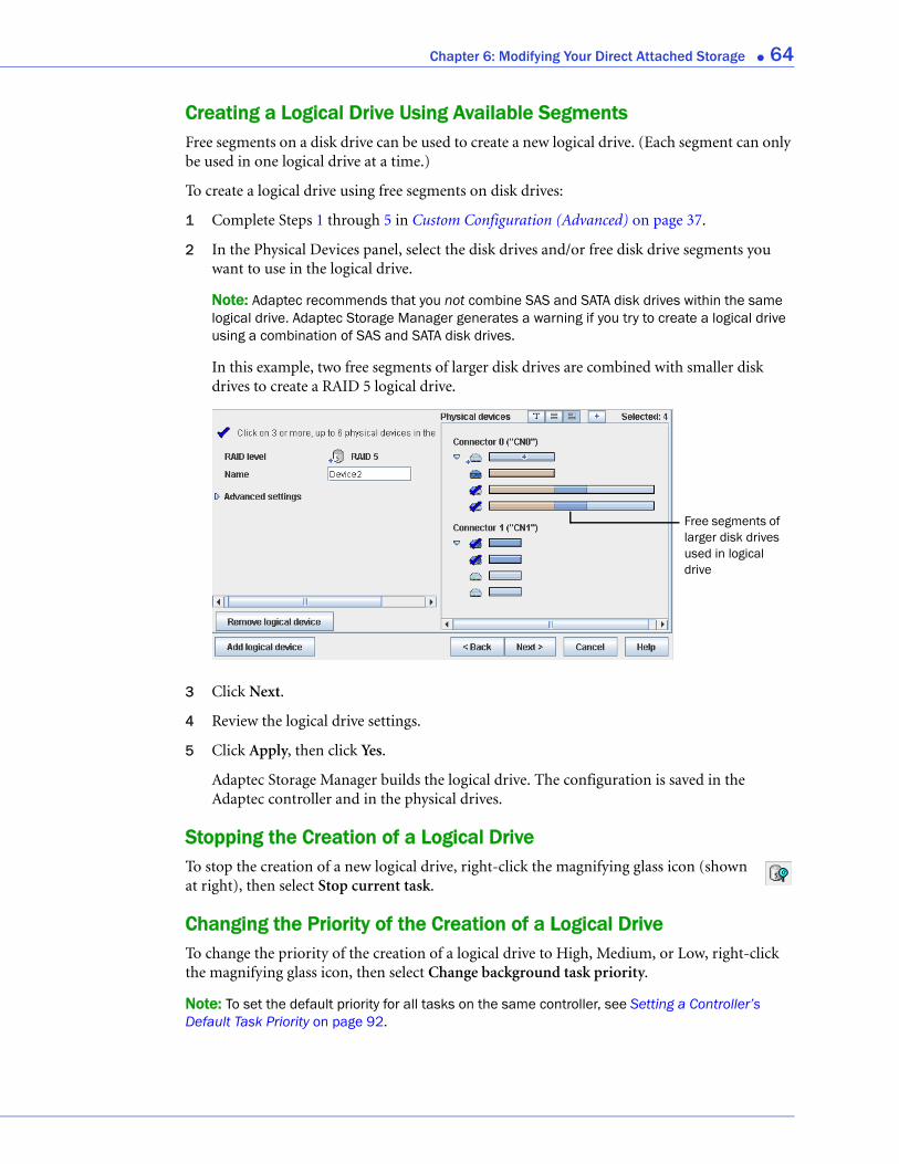
Chapter 6: Modifying Your Direct Attached Storage ● 64
Creating a Logical Drive Using Available SegmentsFree segments on a disk drive can be used to create a new logical drive. (Each segment can only be used in one logical drive at a time.)
To create a logical drive using free segments on disk drives:
1 Complete Steps 1 through 5 in Custom Configuration (Advanced) on page 37.
2 In the Physical Devices panel, select the disk drives and/or free disk drive segments you want to use in the logical drive.
Note: Adaptec recommends that you not combine SAS and SATA disk drives within the same logical drive. Adaptec Storage Manager generates a warning if you try to create a logical drive using a combination of SAS and SATA disk drives.
In this example, two free segments of larger disk drives are combined with smaller disk drives to create a RAID 5 logical drive.
3 Click Next.
4 Review the logical drive settings.
5 Click Apply, then click Yes.
Adaptec Storage Manager builds the logical drive. The configuration is saved in the Adaptec controller and in the physical drives.
Stopping the Creation of a Logical DriveTo stop the creation of a new logical drive, right-click the magnifying glass icon (shown at right), then select Stop current task.
Changing the Priority of the Creation of a Logical DriveTo change the priority of the creation of a logical drive to High, Medium, or Low, right-click the magnifying glass icon, then select Change background task priority.
Note: To set the default priority for all tasks on the same controller, see Setting a Controller’s Default Task Priority on page 92.
Free segments of larger disk drives used in logical drive
Chapter 6: Modifying Your Direct Attached Storage ● 65
Fine-tuning Logical DrivesYou can fine-tune a new or existing logical drive to meet your needs by changing its name or adjusting the Advanced settings described in this section. (Not all options are available for all controllers or all RAID levels.)
Renaming a Logical DriveTo change the name of a logical drive:
1 In the Enterprise View, click the controller associated with the logical drive.
2 In the Logical Devices View, click the logical drive.
3 In the menu bar, select Actions, then click Change logical device name.
4 Type the new name, then click OK.
The logical drive is updated with its new name.
Adjusting a Logical Drive’s Advanced SettingsNote: The default settings in Adaptec Storage Manager are optimal for most users and storage spaces. Only advanced users should change the settings described in this section.
To fine-tune a logical drive:
1 Open the list of Advanced settings.
If you are creating a new logical drive, follow the instructions in Step 7 on page 38.
If you are modifying an existing logical drive:
a In the Enterprise View, click the controller associated with the logical drive.
b In the Logical Devices View, click the logical drive.
c In the menu bar, select Actions, then click Expand or change logical device (shown in the figure in Step 3 on page 65.
d Click Next, then click Advanced settings.
2 Modify the available settings as required for your logical drive (not all options are available for all controllers or all RAID levels):
● Logical drive size (see page 62)
● Stripe size (see page 66)
● Write cache (see page 66)
● Read cache (see page 66)
● Initialize priority (see page 67)
● Initialize method (see page 67)
3 Click Next.
4 To apply the changes immediately, click Apply.
To schedule the changes for later, click Schedule, then set the date and time. (For more information, see Scheduling a Task on page 82.)

Chapter 6: Modifying Your Direct Attached Storage ● 66
Changing the Stripe SizeThe stripe size is the amount of data (in KB) written to one partition before the controller moves to the next partition in a logical drive.
Stripe size options vary, depending on your controller. Normally, the default stripe size provides the best performance.
For RAID 6 and RAID 60 logical drives, the more disk drives there are in the logical drive, the fewer the stripe size options.
Changing the Write Cache SettingThe write cache setting determines when data is stored on a disk drive and when the controller communicates with the operating system.
● Disabled (write-through)—The controller sends (or writes) the data to a disk drive, then sends confirmation to the operating system that the data was received. Use this setting when performance is less important than data protection.
● Enabled (write-back)—The controller sends confirmation to the operating system that the data was received, then writes the data to a disk drive. Use this setting when performance is more important than data protection and you aren’t using a battery-backup cache. Enabled is the default setting.
Note: (RAID 10, 50, and 60 only) All logical drives within a RAID 10/50/60 logical drive must have the same write cache setting—either all write-through or all write-back.
To quickly change the write cache setting:
1 Click the logical drive you want.
2 In the menu bar, select Actions, click Configure write cache, then select Enabled or Disabled as required.
The write cache setting is changed.
Changing the Read Cache SettingWhen read caching is enabled, the controller monitors the read access to a logical drive and, if it sees a pattern, pre-loads the cache with data that seems most likely to be read next, increasing performance.
● Enabled—The controller transfers data from the logical drive to its local cache in portions equal to the stripe size. Use this setting for the best performance when workloads are steady and sequential. Enabled is the default setting.
● Disabled—The controller transfers data from the logical drive to its local cache in portions equal to the system I/O request size. Use this setting for the best performance when workloads are random or the system I/O requests are smaller than the stripe size. (For more information about system I/O requests, refer to your operating system documentation.)
To quickly change the read cache setting:
1 Click the logical drive you want.
2 In the menu bar, select Actions, click Configure read cache, then select Enabled or Disabled as required.
The read cache setting is changed.
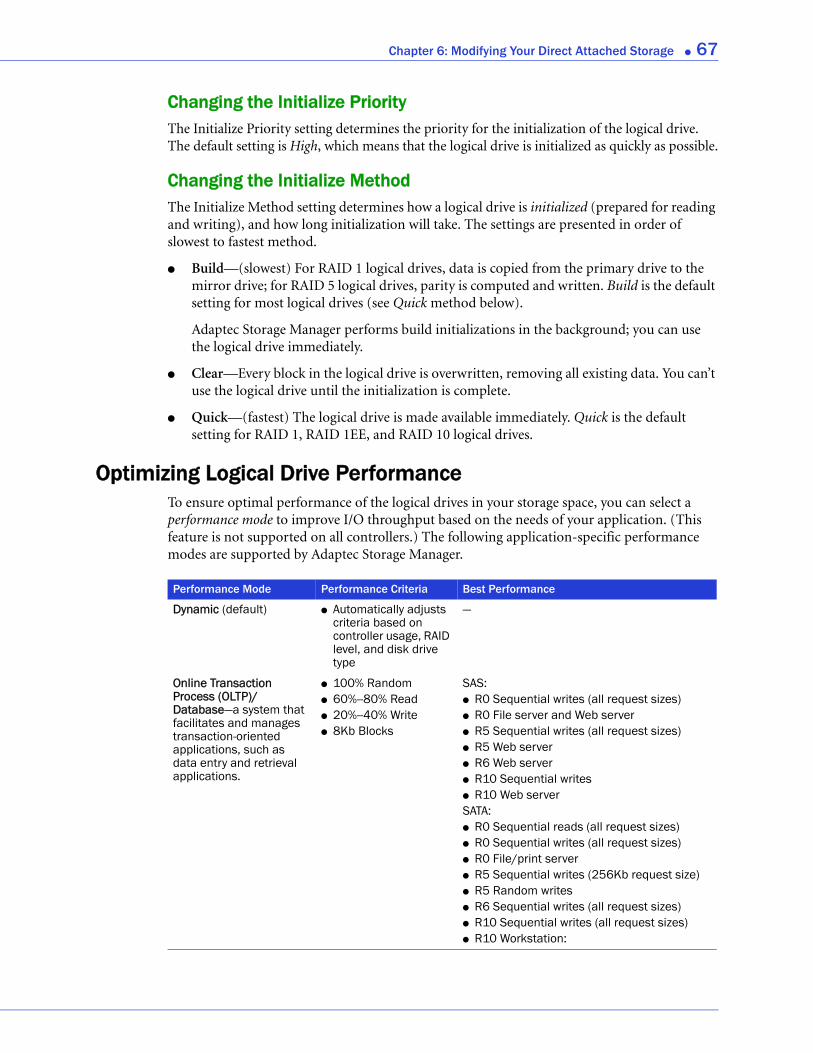
Chapter 6: Modifying Your Direct Attached Storage ● 67
Changing the Initialize PriorityThe Initialize Priority setting determines the priority for the initialization of the logical drive. The default setting is High, which means that the logical drive is initialized as quickly as possible.
Changing the Initialize MethodThe Initialize Method setting determines how a logical drive is initialized (prepared for reading and writing), and how long initialization will take. The settings are presented in order of slowest to fastest method.
● Build—(slowest) For RAID 1 logical drives, data is copied from the primary drive to the mirror drive; for RAID 5 logical drives, parity is computed and written. Build is the default setting for most logical drives (see Quick method below).
Adaptec Storage Manager performs build initializations in the background; you can use the logical drive immediately.
● Clear—Every block in the logical drive is overwritten, removing all existing data. You can’t use the logical drive until the initialization is complete.
● Quick—(fastest) The logical drive is made available immediately. Quick is the default setting for RAID 1, RAID 1EE, and RAID 10 logical drives.
Optimizing Logical Drive PerformanceTo ensure optimal performance of the logical drives in your storage space, you can select a performance mode to improve I/O throughput based on the needs of your application. (This feature is not supported on all controllers.) The following application-specific performance modes are supported by Adaptec Storage Manager.
Performance Mode Performance Criteria Best Performance
Dynamic (default) ● Automatically adjusts criteria based on controller usage, RAID level, and disk drive type
—
Online Transaction Process (OLTP)/Database—a system that facilitates and manages transaction-oriented applications, such as data entry and retrieval applications.
● 100% Random ● 60%--80% Read ● 20%--40% Write ● 8Kb Blocks
SAS:● R0 Sequential writes (all request sizes) ● R0 File server and Web server ● R5 Sequential writes (all request sizes) ● R5 Web server ● R6 Web server ● R10 Sequential writes ● R10 Web server SATA: ● R0 Sequential reads (all request sizes) ● R0 Sequential writes (all request sizes) ● R0 File/print server ● R5 Sequential writes (256Kb request size) ● R5 Random writes ● R6 Sequential writes (all request sizes)● R10 Sequential writes (all request sizes) ● R10 Workstation:
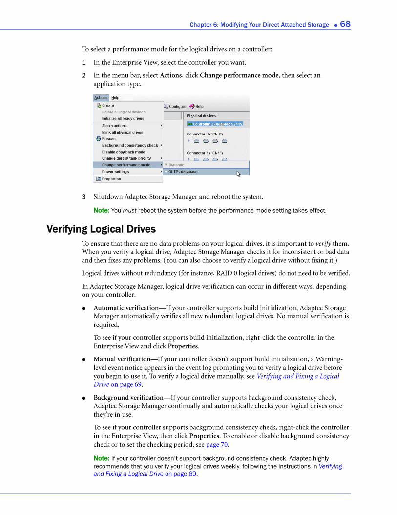
Chapter 6: Modifying Your Direct Attached Storage ● 68
To select a performance mode for the logical drives on a controller:
1 In the Enterprise View, select the controller you want.
2 In the menu bar, select Actions, click Change performance mode, then select an application type.
3 Shutdown Adaptec Storage Manager and reboot the system.
Note: You must reboot the system before the performance mode setting takes effect.
Verifying Logical DrivesTo ensure that there are no data problems on your logical drives, it is important to verify them. When you verify a logical drive, Adaptec Storage Manager checks it for inconsistent or bad data and then fixes any problems. (You can also choose to verify a logical drive without fixing it.)
Logical drives without redundancy (for instance, RAID 0 logical drives) do not need to be verified.
In Adaptec Storage Manager, logical drive verification can occur in different ways, depending on your controller:
● Automatic verification—If your controller supports build initialization, Adaptec Storage Manager automatically verifies all new redundant logical drives. No manual verification is required.
To see if your controller supports build initialization, right-click the controller in the Enterprise View and click Properties.
● Manual verification—If your controller doesn’t support build initialization, a Warning-level event notice appears in the event log prompting you to verify a logical drive before you begin to use it. To verify a logical drive manually, see Verifying and Fixing a Logical Drive on page 69.
● Background verification—If your controller supports background consistency check, Adaptec Storage Manager continually and automatically checks your logical drives once they’re in use.
To see if your controller supports background consistency check, right-click the controller in the Enterprise View, then click Properties. To enable or disable background consistency check or to set the checking period, see page 70.
Note: If your controller doesn’t support background consistency check, Adaptec highly recommends that you verify your logical drives weekly, following the instructions in Verifying and Fixing a Logical Drive on page 69.
Chapter 6: Modifying Your Direct Attached Storage ● 69
Verifying and Fixing a Logical DriveNote: To verify a logical drive without fixing it, see page 69.
While Adaptec Storage Manager verifies and fixes a logical drive, you can’t complete any other tasks on the controller. Because the verification can take a long time to complete, you may want to schedule it as a task to be completed overnight or on a weekend.
To verify and fix a logical drive:
1 Ensure that no activity is taking place on the controller associated with the logical drive you want to verify and fix.
2 In the Enterprise View, click the controller.
3 In the Logical Devices View, click the logical drive.
4 In the menu bar, select Actions, then click Verify with fix.
5 To begin the verification immediately, click Yes.
To schedule the verification, click Schedule, then set the date and time. You can also choose to set the verification as a recurring task. (For more information on scheduling tasks, see page 82.)
Note: Don’t power off the system while the verification is in progress. If you do, the verification will stop.
While the verification is in progress, the logical drive is shown as an animated icon (as shown at right) to indicate that the task is in progress.
When the verification is complete, an event notice is generated in the local system’s event log (and broadcast to other systems, if you have event notification set up—see Notifying Users by Event Log Message About Status and Activity on page 103).
You can now continue working on the controller.
Verifying a Logical Drive (Without Fix)Note: To verify and fix a logical drive, see page 69.
While Adaptec Storage Manager verifies a logical drive, you can’t complete any other tasks on the controller associated with that logical drive. Because verification takes a long time to complete, you may want to schedule it as a task to be completed overnight or on a weekend.
To verify a logical drive:
1 Ensure that no activity is taking place on the controller associated with the logical drive you want to verify and fix.
2 In the Enterprise View, click the controller.
3 In the Logical Devices View, click the logical drive.
4 In the menu bar, select Actions, then click Verify.
Chapter 6: Modifying Your Direct Attached Storage ● 70
5 To begin the verification immediately, click Yes.
To schedule the verification for later, click Schedule, set the date and time, then click Apply. You can also set the verification to recur. (For more information on scheduling tasks, see page 82.)
Note: Don’t power off the system while the verification is in progress. If you do, the verification will stop.
While the verification is in progress, the logical drive is shown as an animated icon (as shown at right) to indicate that the task is in progress.
When the verification is complete, an event notice is generated in the local system’s event log (and broadcast to other systems, if you have event notification set up—see Notifying Users by Event Log Message About Status and Activity on page 103).
You can now continue working on the controller.
Enabling/Disabling Background Consistency CheckIf your controller supports background consistency check, Adaptec Storage Manager continually and automatically checks your logical drives once they’re in use. (To see if your controller supports background consistency check, right-click the controller in the Enterprise View, then click Properties.)
To enable or disable background consistency check:
1 In the Enterprise View, click the controller.
2 In the menu bar, select Actions, then click Enable (Disable) background consistency check.
The controller is updated with the new setting.
Setting the Background Consistency Check Period
You can choose how often Adaptec Storage Manager checks for inconsistent or bad data on your logical drives and hot-spares.
To change the background consistency check period:
1 In the Enterprise view, select a controller.
2 Right-click Background Consistency Check, then select Change period.
The Change background consistency check period window opens.
3 Adjust the slider control from Very Slow (365 days) to Fast (10 days). Alternatively, in the New Period field, use the arrow keys to increase or decrease the setting.
4 Click OK.
Increasing the Capacity of a Logical DriveYou can add more disk drive space to a logical drive to increase its capacity (or expand it).
Note: The maximum size of a logical drive varies by controller. Refer to your controller’s documentation for more information.
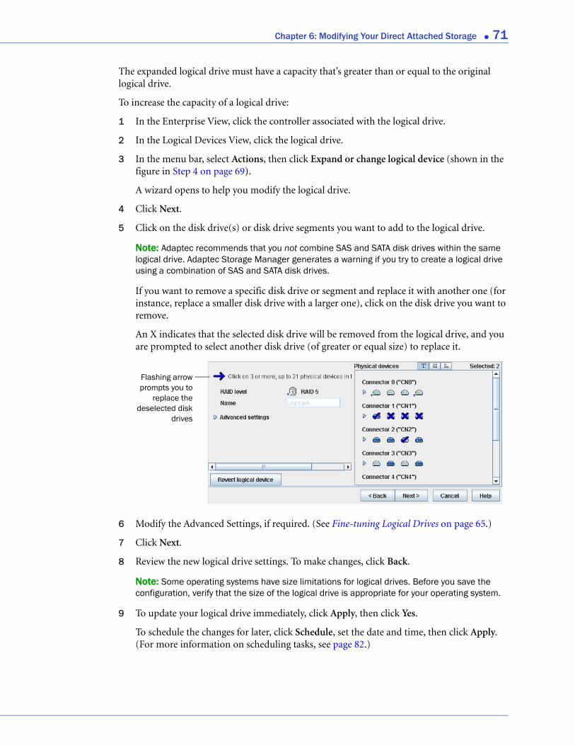
Chapter 6: Modifying Your Direct Attached Storage ● 71
The expanded logical drive must have a capacity that’s greater than or equal to the original logical drive.
To increase the capacity of a logical drive:
1 In the Enterprise View, click the controller associated with the logical drive.
2 In the Logical Devices View, click the logical drive.
3 In the menu bar, select Actions, then click Expand or change logical device (shown in the figure in Step 4 on page 69).
A wizard opens to help you modify the logical drive.
4 Click Next.
5 Click on the disk drive(s) or disk drive segments you want to add to the logical drive.
Note: Adaptec recommends that you not combine SAS and SATA disk drives within the same logical drive. Adaptec Storage Manager generates a warning if you try to create a logical drive using a combination of SAS and SATA disk drives.
If you want to remove a specific disk drive or segment and replace it with another one (for instance, replace a smaller disk drive with a larger one), click on the disk drive you want to remove.
An X indicates that the selected disk drive will be removed from the logical drive, and you are prompted to select another disk drive (of greater or equal size) to replace it.
6 Modify the Advanced Settings, if required. (See Fine-tuning Logical Drives on page 65.)
7 Click Next.
8 Review the new logical drive settings. To make changes, click Back.
Note: Some operating systems have size limitations for logical drives. Before you save the configuration, verify that the size of the logical drive is appropriate for your operating system.
9 To update your logical drive immediately, click Apply, then click Yes.
To schedule the changes for later, click Schedule, set the date and time, then click Apply. (For more information on scheduling tasks, see page 82.)
Flashing arrowprompts you to
replace thedeselected disk
drives

Chapter 6: Modifying Your Direct Attached Storage ● 72
Extending a Partition on a Logical Drive(Windows 2003, Windows XP, and Windows 2000 only) If you have expanded a logical drive, you can extend the partition on that logical drive to use the newly added space. Refer to your operating system instructions for more information.
Changing the RAID Level of a Logical DriveAs your requirements change, you can change the RAID level of your logical drives to suit your needs. You may want to do this to add redundancy to protect your data, or improve data availability for speedier access to your data. See Selecting the Best RAID Level on page 148 for more information.
Changing the RAID level normally requires one or more disk drives to be added to or removed from the logical drive. Adaptec Storage Manager won’t allow you to continue unless you have the right number of disk drives available.
To change the RAID level of a logical drive:
1 In the Enterprise View, click the controller associated with the logical drive.
2 In the Logical Devices View, click the logical drive.
3 In the menu bar, select Actions, then click Expand or change logical device (see page 71).
A wizard opens to help you change the RAID level.
4 Select a new RAID level, then click Next. Only valid options are offered.
5 In the Logical Devices panel, select the disk drives you want to use in the modified logical drive.
Note: Adaptec recommends that you not combine SAS and SATA disk drives within the same logical drive. Adaptec Storage Manager generates a warning if you try to create a logical drive using a combination of SAS and SATA disk drives.
Adaptec Storage Manager prompts you to select the correct number of disk drives.
If you want to remove a specific disk drive and replace it with another one (for instance, replace a smaller disk drive with a larger one), click on the disk drive you want to remove. An X indicates that the selected disk drive will be removed from the logical drive. (See the figure on page 71 for an example.)
6 Modify the Advanced Settings, if required. (See Fine-tuning Logical Drives on page 65.)
7 Click Next.
8 Review the new logical drive settings. To make changes, click Back.
Note: Some operating systems have size limitations for logical drives. Before you save the configuration, verify that the size of the logical drive is appropriate for your operating system.
9 To update your logical drive immediately, click Apply, then click Yes.
To schedule the changes for later, click Schedule, set the date and time, then click Apply. (For more information, see page 82.)
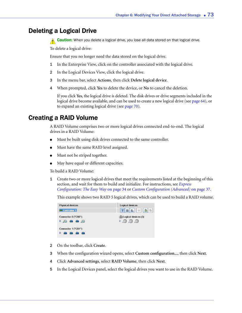
Chapter 6: Modifying Your Direct Attached Storage ● 73
Deleting a Logical DriveCaution: When you delete a logical drive, you lose all data stored on that logical drive.
To delete a logical drive:
Ensure that you no longer need the data stored on the logical drive.
1 In the Enterprise View, click on the controller associated with the logical drive.
2 In the Logical Devices View, click the logical drive.
3 In the menu bar, select Actions, then click Delete logical device.
4 When prompted, click Yes to delete the device, or No to cancel the deletion.
If you click Yes, the logical drive is deleted. The disk drives or drive segments included in the logical drive become available, and can be used to create a new logical drive (see page 64), or to expand an existing logical drive (see page 70).
Creating a RAID VolumeA RAID Volume comprises two or more logical drives connected end-to-end. The logical drives in a RAID Volume:
● Must be built using disk drives connected to the same controller.
● Must have the same RAID level assigned.
● Must not be striped together.
● May have equal or different capacities.
To build a RAID Volume:
1 Create two or more logical drives that meet the requirements listed at the beginning of this section, and wait for them to build and initialize. For instructions, see Express Configuration: The Easy Way on page 34 or Custom Configuration (Advanced) on page 37.
This example shows two RAID 5 logical drives, which can be used to build a RAID volume.
2 On the toolbar, click Create.
3 When the configuration wizard opens, select Custom configuration..., then click Next.
4 Click Advanced settings, select RAID Volume, then click Next.
5 In the Logical Devices panel, select the logical drives you want to use in the RAID Volume.
!

Chapter 6: Modifying Your Direct Attached Storage ● 74
Adaptec Storage Manager prompts you to select the correct number of logical drives.
6 Modify the Advanced Settings, if required. (See Fine-tuning Logical Drives on page 65 for more information.)
7 Click Next to review the RAID Volume settings. To make changes, click Back.
This example shows one RAID Volume ready to be created.
8 Click Apply, then click Yes.
Adaptec Storage Manager builds the RAID Volume. The configuration is saved on the Adaptec controller and on the physical drives. Adaptec Storage Manager replaces the individual logical drives with a single RAID Volume in the Logical Devices View.
9 Partition and format your RAID Volume. See page 36 for more information.
Number of disk drives required
RAID Volume replaces the two RAID 5 logical drives shown in Step 1
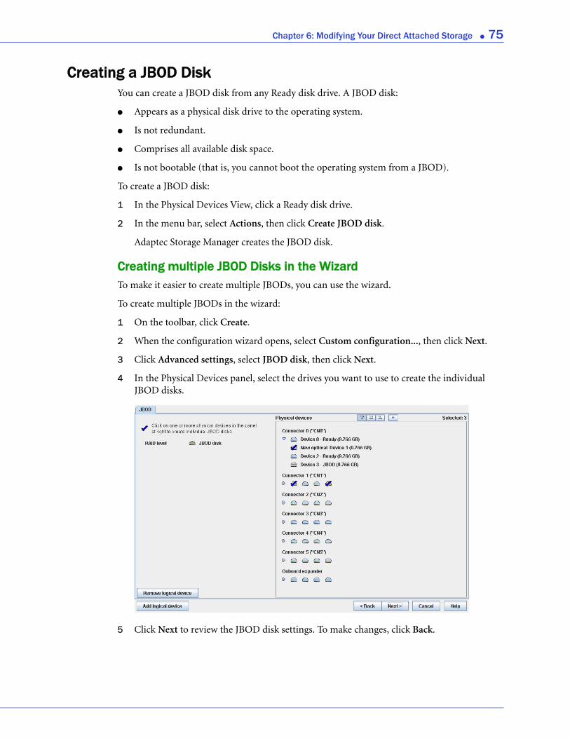
Chapter 6: Modifying Your Direct Attached Storage ● 75
Creating a JBOD DiskYou can create a JBOD disk from any Ready disk drive. A JBOD disk:
● Appears as a physical disk drive to the operating system.
● Is not redundant.
● Comprises all available disk space.
● Is not bootable (that is, you cannot boot the operating system from a JBOD).
To create a JBOD disk:
1 In the Physical Devices View, click a Ready disk drive.
2 In the menu bar, select Actions, then click Create JBOD disk.
Adaptec Storage Manager creates the JBOD disk.
Creating multiple JBOD Disks in the WizardTo make it easier to create multiple JBODs, you can use the wizard.
To create multiple JBODs in the wizard:
1 On the toolbar, click Create.
2 When the configuration wizard opens, select Custom configuration..., then click Next.
3 Click Advanced settings, select JBOD disk, then click Next.
4 In the Physical Devices panel, select the drives you want to use to create the individual JBOD disks.
5 Click Next to review the JBOD disk settings. To make changes, click Back.
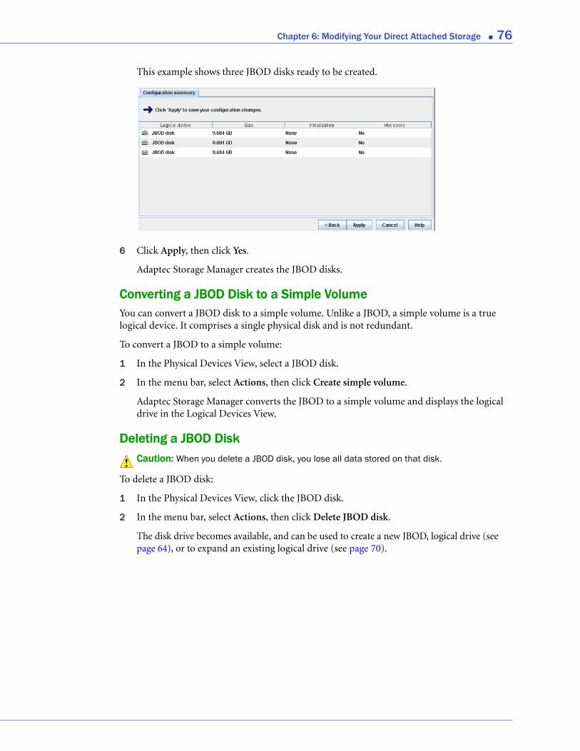
Chapter 6: Modifying Your Direct Attached Storage ● 76
This example shows three JBOD disks ready to be created.
6 Click Apply, then click Yes.
Adaptec Storage Manager creates the JBOD disks.
Converting a JBOD Disk to a Simple VolumeYou can convert a JBOD disk to a simple volume. Unlike a JBOD, a simple volume is a true logical device. It comprises a single physical disk and is not redundant.
To convert a JBOD to a simple volume:
1 In the Physical Devices View, select a JBOD disk.
2 In the menu bar, select Actions, then click Create simple volume.
Adaptec Storage Manager converts the JBOD to a simple volume and displays the logical drive in the Logical Devices View.
Deleting a JBOD DiskCaution: When you delete a JBOD disk, you lose all data stored on that disk.
To delete a JBOD disk:
1 In the Physical Devices View, click the JBOD disk.
2 In the menu bar, select Actions, then click Delete JBOD disk.
The disk drive becomes available, and can be used to create a new JBOD, logical drive (see page 64), or to expand an existing logical drive (see page 70).
!
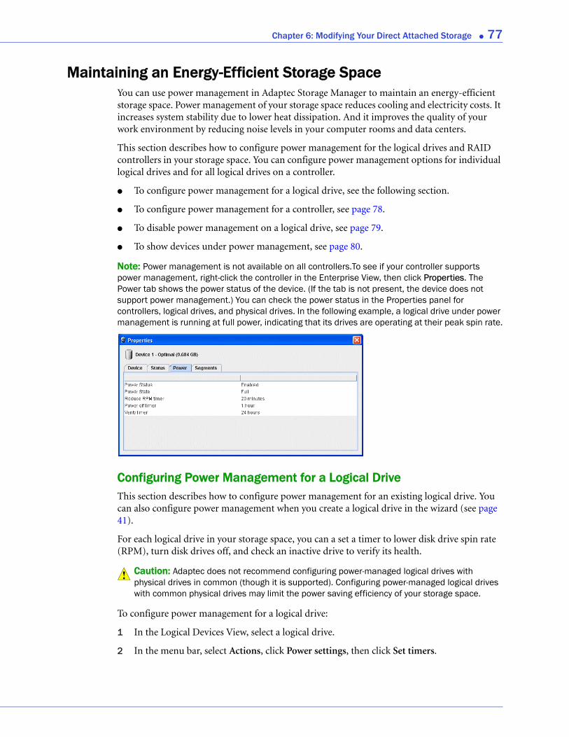
Chapter 6: Modifying Your Direct Attached Storage ● 77
Maintaining an Energy-Efficient Storage SpaceYou can use power management in Adaptec Storage Manager to maintain an energy-efficient storage space. Power management of your storage space reduces cooling and electricity costs. It increases system stability due to lower heat dissipation. And it improves the quality of your work environment by reducing noise levels in your computer rooms and data centers.
This section describes how to configure power management for the logical drives and RAID controllers in your storage space. You can configure power management options for individual logical drives and for all logical drives on a controller.
● To configure power management for a logical drive, see the following section.
● To configure power management for a controller, see page 78.
● To disable power management on a logical drive, see page 79.
● To show devices under power management, see page 80.
Note: Power management is not available on all controllers.To see if your controller supports power management, right-click the controller in the Enterprise View, then click Properties. The Power tab shows the power status of the device. (If the tab is not present, the device does not support power management.) You can check the power status in the Properties panel for controllers, logical drives, and physical drives. In the following example, a logical drive under power management is running at full power, indicating that its drives are operating at their peak spin rate.
Configuring Power Management for a Logical DriveThis section describes how to configure power management for an existing logical drive. You can also configure power management when you create a logical drive in the wizard (see page 41).
For each logical drive in your storage space, you can a set a timer to lower disk drive spin rate (RPM), turn disk drives off, and check an inactive drive to verify its health.
Caution: Adaptec does not recommend configuring power-managed logical drives with physical drives in common (though it is supported). Configuring power-managed logical drives with common physical drives may limit the power saving efficiency of your storage space.
To configure power management for a logical drive:
1 In the Logical Devices View, select a logical drive.
2 In the menu bar, select Actions, click Power settings, then click Set timers.
!
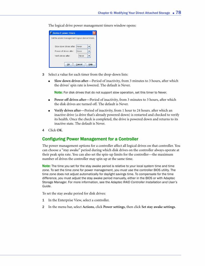
Chapter 6: Modifying Your Direct Attached Storage ● 78
The logical drive power management timers window opens:
3 Select a value for each timer from the drop-down lists:
● Slow down drives after—Period of inactivity, from 3 minutes to 3 hours, after which the drives’ spin rate is lowered. The default is Never.
Note: For disk drives that do not support slow operation, set this timer to Never.
● Power off drives after—Period of inactivity, from 3 minutes to 3 hours, after which the disk drives are turned off. The default is Never.
● Verify drives after—Period of inactivity, from 1 hour to 24 hours. after which an inactive drive (a drive that’s already powered down) is restarted and checked to verify its health. Once the check is completed, the drive is powered down and returns to its inactive state. The default is Never.
4 Click OK.
Configuring Power Management for a ControllerThe power management options for a controller affect all logical drives on that controller. You can choose a “stay awake” period during which disk drives on the controller always operate at their peak spin rate. You can also set the spin-up limits for the controller—the maximum number of drives the controller may spin up at the same time.
Note: The time you set for the stay awake period is relative to your local system time and time zone. To set the time zone for power management, you must use the controller BIOS utility. The time zone does not adjust automatically for daylight savings time. To compensate for the time difference, you must adjust the stay awake period manually, either in the BIOS or with Adaptec Storage Manager. For more information, see the Adaptec RAID Controller Installation and User’s Guide.
To set the stay awake period for disk drives:
1 In the Enterprise View, select a controller.
2 In the menu bar, select Actions, click Power settings, then click Set stay awake settings.
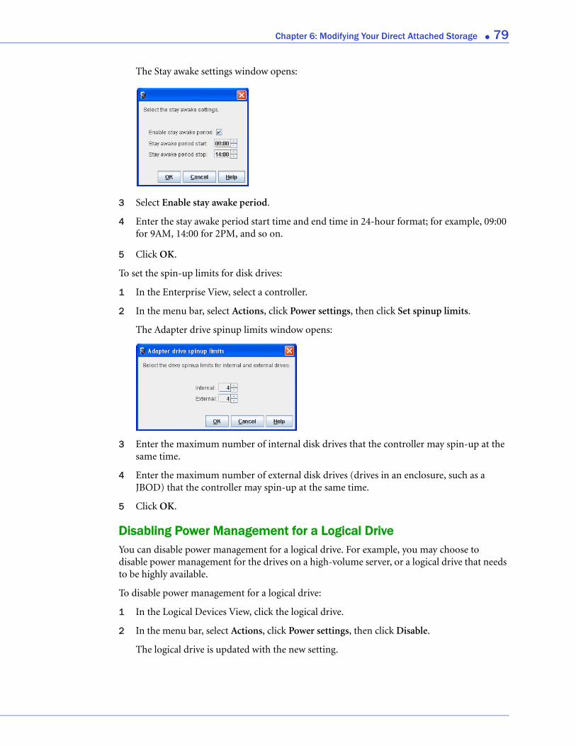
Chapter 6: Modifying Your Direct Attached Storage ● 79
The Stay awake settings window opens:
3 Select Enable stay awake period.
4 Enter the stay awake period start time and end time in 24-hour format; for example, 09:00 for 9AM, 14:00 for 2PM, and so on.
5 Click OK.
To set the spin-up limits for disk drives:
1 In the Enterprise View, select a controller.
2 In the menu bar, select Actions, click Power settings, then click Set spinup limits.
The Adapter drive spinup limits window opens:
3 Enter the maximum number of internal disk drives that the controller may spin-up at the same time.
4 Enter the maximum number of external disk drives (drives in an enclosure, such as a JBOD) that the controller may spin-up at the same time.
5 Click OK.
Disabling Power Management for a Logical DriveYou can disable power management for a logical drive. For example, you may choose to disable power management for the drives on a high-volume server, or a logical drive that needs to be highly available.
To disable power management for a logical drive:
1 In the Logical Devices View, click the logical drive.
2 In the menu bar, select Actions, click Power settings, then click Disable.
The logical drive is updated with the new setting.
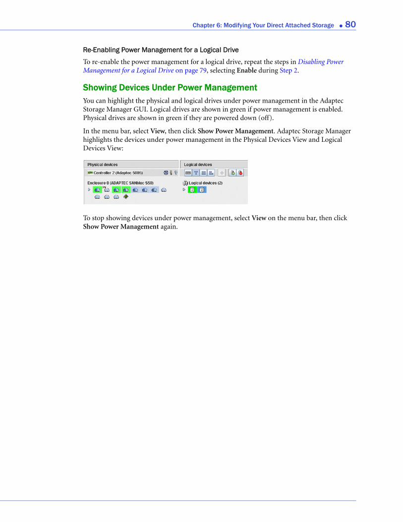
Chapter 6: Modifying Your Direct Attached Storage ● 80
Re-Enabling Power Management for a Logical Drive
To re-enable the power management for a logical drive, repeat the steps in Disabling Power Management for a Logical Drive on page 79, selecting Enable during Step 2.
Showing Devices Under Power ManagementYou can highlight the physical and logical drives under power management in the Adaptec Storage Manager GUI. Logical drives are shown in green if power management is enabled. Physical drives are shown in green if they are powered down (off).
In the menu bar, select View, then click Show Power Management. Adaptec Storage Manager highlights the devices under power management in the Physical Devices View and Logical Devices View:
To stop showing devices under power management, select View on the menu bar, then click Show Power Management again.
7
Scheduling Recurring or Resource-Intensive JobsIn this chapter...
Scheduling a Task ................................................................................................................... 82
Opening the Task Manager .................................................................................................... 83
Monitoring Tasks.................................................................................................................... 84
Modifying a Task .................................................................................................................... 85
Deleting a Task........................................................................................................................ 85
Disabling the Task Manager................................................................................................... 85
Adaptec Storage Manager allows you to schedule some types of jobs (or tasks) to complete at convenient times. Additionally, you can schedule some tasks to recur at preset times.
A Task Manager utility helps you manage the tasks you schedule.
This chapter describes how to schedule, monitor, and manage tasks.

Chapter 7: Scheduling Recurring or Resource-Intensive Jobs ● 82
Scheduling a TaskIf a task is lengthy and limits access to components on your storage space, you may want to set a date and time for the task to complete, instead of running the task while there is activity on your storage space.
If a task must be performed regularly, you can schedule it to recur at preset times.
You can schedule these Adaptec Storage Manager tasks:
● Expanding a logical drive
● Changing a logical drive’s RAID level
● Modifying the stripe size of a logical drive
● Verifying a logical drive
● Verifying and fixing a logical drive
To schedule one of these tasks:
1 Complete each step of the task until you are prompted to click Apply. (Don’t click Apply.)
2 Click Schedule.
The schedule window opens. (The window you see may be different from the one shown in this example, depending on which type of task you are scheduling.)
Schedule button
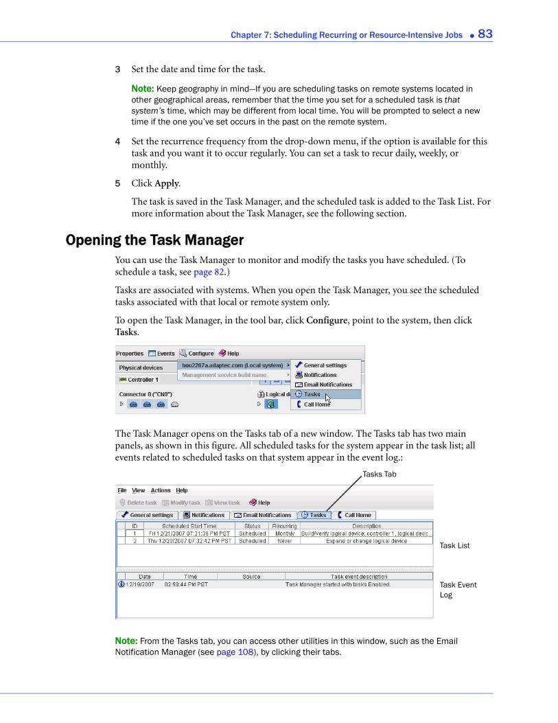
Chapter 7: Scheduling Recurring or Resource-Intensive Jobs ● 83
3 Set the date and time for the task.
Note: Keep geography in mind—If you are scheduling tasks on remote systems located in other geographical areas, remember that the time you set for a scheduled task is that system’s time, which may be different from local time. You will be prompted to select a new time if the one you’ve set occurs in the past on the remote system.
4 Set the recurrence frequency from the drop-down menu, if the option is available for this task and you want it to occur regularly. You can set a task to recur daily, weekly, or monthly.
5 Click Apply.
The task is saved in the Task Manager, and the scheduled task is added to the Task List. For more information about the Task Manager, see the following section.
Opening the Task ManagerYou can use the Task Manager to monitor and modify the tasks you have scheduled. (To schedule a task, see page 82.)
Tasks are associated with systems. When you open the Task Manager, you see the scheduled tasks associated with that local or remote system only.
To open the Task Manager, in the tool bar, click Configure, point to the system, then click Tasks.
The Task Manager opens on the Tasks tab of a new window. The Tasks tab has two main panels, as shown in this figure. All scheduled tasks for the system appear in the task list; all events related to scheduled tasks on that system appear in the event log.:
Note: From the Tasks tab, you can access other utilities in this window, such as the Email Notification Manager (see page 108), by clicking their tabs.
Task Event Log
Task List
Tasks Tab
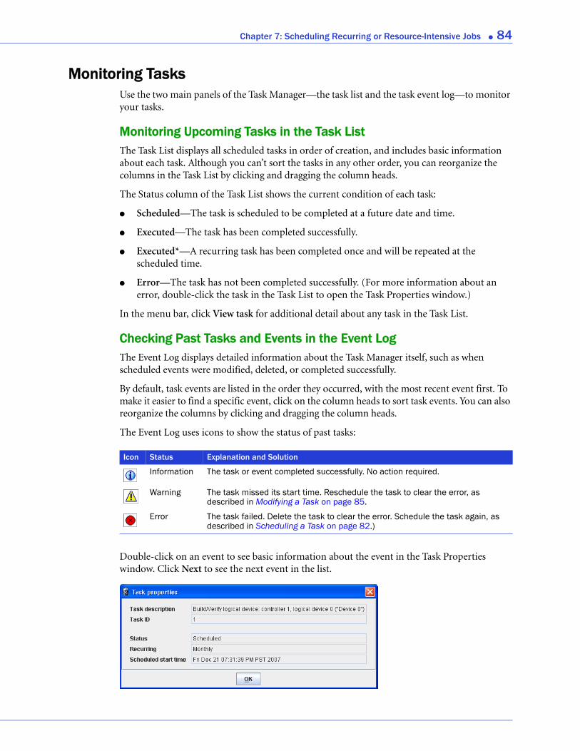
Chapter 7: Scheduling Recurring or Resource-Intensive Jobs ● 84
Monitoring TasksUse the two main panels of the Task Manager—the task list and the task event log—to monitor your tasks.
Monitoring Upcoming Tasks in the Task ListThe Task List displays all scheduled tasks in order of creation, and includes basic information about each task. Although you can’t sort the tasks in any other order, you can reorganize the columns in the Task List by clicking and dragging the column heads.
The Status column of the Task List shows the current condition of each task:
● Scheduled—The task is scheduled to be completed at a future date and time.
● Executed—The task has been completed successfully.
● Executed*—A recurring task has been completed once and will be repeated at the scheduled time.
● Error—The task has not been completed successfully. (For more information about an error, double-click the task in the Task List to open the Task Properties window.)
In the menu bar, click View task for additional detail about any task in the Task List.
Checking Past Tasks and Events in the Event LogThe Event Log displays detailed information about the Task Manager itself, such as when scheduled events were modified, deleted, or completed successfully.
By default, task events are listed in the order they occurred, with the most recent event first. To make it easier to find a specific event, click on the column heads to sort task events. You can also reorganize the columns by clicking and dragging the column heads.
The Event Log uses icons to show the status of past tasks:
Double-click on an event to see basic information about the event in the Task Properties window. Click Next to see the next event in the list.
Icon Status Explanation and Solution
Information The task or event completed successfully. No action required.
Warning The task missed its start time. Reschedule the task to clear the error, as described in Modifying a Task on page 85.
Error The task failed. Delete the task to clear the error. Schedule the task again, as described in Scheduling a Task on page 82.)
Chapter 7: Scheduling Recurring or Resource-Intensive Jobs ● 85
Modifying a TaskIf your requirements change, you can reschedule a task to a different date or time. You can also modify the task description that appears in the Task List. Creating a custom task description makes it easier to find the task in the Task List.
To modify a scheduled task:
1 In the tool bar, click Configure, point to the system you want, then click Tasks (as shown on page 83).
2 In the Task Manager, select the task you want to change, then click Modify task.
3 In the Modify Task window, make the required changes, then click OK.
The task and Task List are updated with the new information.
What if a task misses its start time?Tasks scheduled in Adaptec Storage Manager include an automatic 30-minute grace period following their start time, to accommodate temporary interruptions. For instance, if there’s a brief power outage a task will run once normal conditions resume, if the interruption lasts no longer than 30 minutes past the scheduled start time.
If a task misses its start time, it must be rescheduled. For instructions, see Modifying a Task.
If a recurring task misses its start time, it is automatically rescheduled to run at the next scheduled interval.
Deleting a TaskIf a scheduled task is no longer required, you can delete it from the Task Manager.
To delete a task:
1 In the tool bar, click Configure, point to the system associated with the task you want to delete, then click Tasks (as shown on page 83).
2 In the Task Manager, select the task you want to delete, then click Delete task.
3 Click Yes to confirm the deletion.
The task is deleted.
Disabling the Task ManagerThe Task Manager is enabled by default. If you do not wish to schedule tasks on a selected system, you can disable it.
Note: If you disable the Task Manager, no scheduled tasks will run on that system. No other systems are affected.
To disable the Task Manager:
1 In the tool bar, click Configure, point to the system whose Task Manager you want to disable, then click Tasks (as shown on page 83).
Chapter 7: Scheduling Recurring or Resource-Intensive Jobs ● 86
2 In the menu bar, click Actions, then click Disable Task Scheduler.
The Task Manager is disabled. The Tasks tab (shown at right) shows the red ‘disabled’ icon.
Note: When the Task Manager is disabled, a brief three-tone alert sounds each time you open and log in to Adaptec Storage Manager. Scheduled tasks in the Task List will not run while the Task Manager is disabled.
Re-enabling the Task ManagerTo re-enable the Task Manager, repeat the steps in Disabling the Task Manager on page 85, selecting Enable Task Scheduler during Step 2.
Scheduled tasks that have missed their start times must be rescheduled if you want them to run. See Modifying a Task on page 85 for instructions.
Scheduled tasks that did not miss their start time while the Task Manager was disabled will run as scheduled.
8
Maintaining Physical DevicesIn this chapter...Viewing Component Properties ............................................................................................ 88
Blinking a Component........................................................................................................... 88
Working with Failed or Failing Disk Drives.......................................................................... 89
Initializing and Erasing Disk Drives...................................................................................... 89
Working with Controllers ...................................................................................................... 90
Testing and Silencing System and Enclosure Alarms ........................................................... 93
Updating the Controller BIOS and Firmware ...................................................................... 96
This chapter describes how to manage the controllers, disk drives, and enclosures in your storage space.
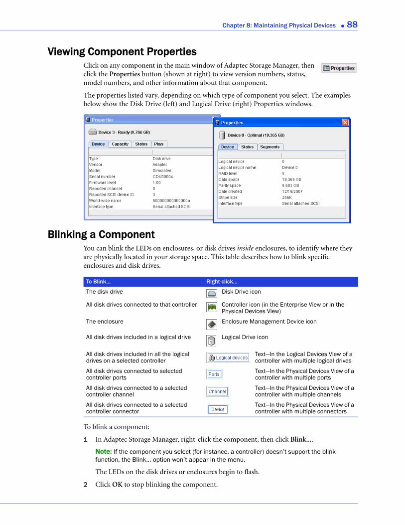
Chapter 8: Maintaining Physical Devices ● 88
Viewing Component PropertiesClick on any component in the main window of Adaptec Storage Manager, then click the Properties button (shown at right) to view version numbers, status, model numbers, and other information about that component.
The properties listed vary, depending on which type of component you select. The examples below show the Disk Drive (left) and Logical Drive (right) Properties windows.
Blinking a ComponentYou can blink the LEDs on enclosures, or disk drives inside enclosures, to identify where they are physically located in your storage space. This table describes how to blink specific enclosures and disk drives.
To blink a component:
1 In Adaptec Storage Manager, right-click the component, then click Blink....
Note: If the component you select (for instance, a controller) doesn’t support the blink function, the Blink... option won’t appear in the menu.
The LEDs on the disk drives or enclosures begin to flash.
2 Click OK to stop blinking the component.
To Blink... Right-click...
The disk drive Disk Drive icon
All disk drives connected to that controller Controller icon (in the Enterprise View or in the Physical Devices View)
The enclosure Enclosure Management Device icon
All disk drives included in a logical drive Logical Drive icon
All disk drives included in all the logical drives on a selected controller
Text—In the Logical Devices View of a controller with multiple logical drives
All disk drives connected to selected controller ports
Text—In the Physical Devices View of a controller with multiple ports
All disk drives connected to a selected controller channel
Text—In the Physical Devices View of a controller with multiple channels
All disk drives connected to a selected controller connector
Text—In the Physical Devices View of a controller with multiple connectors
Chapter 8: Maintaining Physical Devices ● 89
Working with Failed or Failing Disk DrivesThis section describes how to use Adaptec Storage Manager to manage failed or failing disk drives in your storage space.
Replacing Disk Drives in a Logical DriveYou can replace one or more disk drives in a logical drive. You may want to do this to upgrade to larger disk drives, or to make disk drive size uniform across the logical drive.
Caution: If another disk drive in the logical drive fails during rebuild (see page 136), you may lose data.
To replace a disk drive in a logical drive:
1 In the Physical Devices View, click the disk drive you want to replace.
2 Set the drive state to failed. (See page 89.)
3 Remove and replace the disk drive with one of equal or larger size.
4 Wait for the logical drive to rebuild. (See page 136.)
5 Repeat Steps 1 to 4 for all the disk drives you want to replace.
For help solving disk drive problems, see Recovering from a Disk Drive Failure on page 133.
Setting a Disk Drive to ‘Failed’Before you can remove a disk drive, you should set it to a failed state to protect your data.
Caution: You may lose data or damage your disk drive if you remove a disk drive without first setting it to a failed state.
You can set a disk drive to a failed state if:
● The disk drive is not part of a logical drive, or
● The disk drive is part of a redundant, healthy logical drive
You can’t set a disk drive to a failed state if doing so will take a logical drive offline.
To set a disk drive to a failed state:
1 In the Physical Devices View, click the disk drive.
2 In the menu bar, select Actions, then click Set drive state to failed.
3 Click Yes to set the drive status to failed.
4 Remove and replace the disk drive.
5 If the logical drive that the disk drive belongs to is failed, see Recovering from a Disk Drive Failure on page 133.
Initializing and Erasing Disk DrivesThis section describes how to use Adaptec Storage Manager to erase data and metadata (including logical drive information) from the disk drives in your storage space.
!
!
Chapter 8: Maintaining Physical Devices ● 90
Initializing Disk DrivesYou can use Adaptec Storage Manager to initialize any disk drives that are in a Ready state, if required. You may want to do this to erase all existing data and metadata (including all logical drive information) before using the disk drive in a new logical device or as a hot spare.
Caution: Do not initialize a disk drive that is part of a logical drive. Initializing a disk drive that’s part of a logical drive may make the logical drive unusable. Back up all data from your disk drive before you initialize it.
To initialize a single disk drive:
1 In the Physical Devices view, click the disk drive you want to initialize.
2 In the menu bar, select Actions, then click Initialize.
3 Click Yes to initialize the disk drive.
The initialization begins.
To initialize all ready disk drives on a controller:
1 In the Enterprise View, click the controller whose disk drives you want to initialize.
2 In the menu bar, select Actions, then click Initialize all ready drives.
3 Click Yes to initialize the disk drives.
The initialization begins.
Clearing Disk DrivesYou can use Adaptec Storage Manager to erase all existing data on any disk drives that are in the Ready state, if required. You can clear the drive, or clear the drive securely to completely destroy any data on the disk. Secure erase amounts to electronic “data shredding.”
To clear a disk drive:
1 In the Physical Devices view, click the disk drive you want to clear.
2 In the menu bar, select Actions, then click Clear.
3 Click Yes to clear the disk drive.
To securely erase a disk drive:
1 In the Physical Devices view, click the disk drive you want to clear.
2 In the menu bar, select Actions, then click Secure erase.
3 Click Yes to securely erase the disk drive.
Working with ControllersThis section describes how to use Adaptec Storage Manager to manage the controllers that are part of your storage space:
● To register a new controller, see the following section.
● To test a controller alarm, see page 91.
● To silence a controller alarm, see page 91.
!
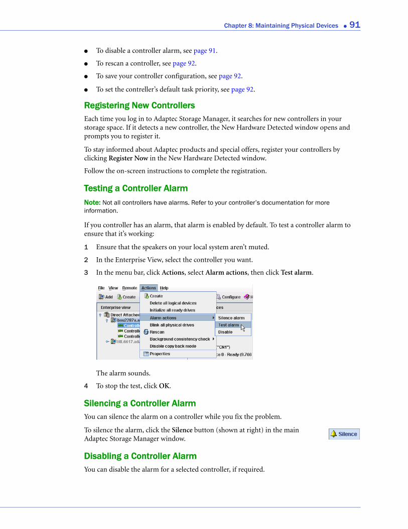
Chapter 8: Maintaining Physical Devices ● 91
● To disable a controller alarm, see page 91.
● To rescan a controller, see page 92.
● To save your controller configuration, see page 92.
● To set the contreller’s default task priority, see page 92.
Registering New ControllersEach time you log in to Adaptec Storage Manager, it searches for new controllers in your storage space. If it detects a new controller, the New Hardware Detected window opens and prompts you to register it.
To stay informed about Adaptec products and special offers, register your controllers by clicking Register Now in the New Hardware Detected window.
Follow the on-screen instructions to complete the registration.
Testing a Controller AlarmNote: Not all controllers have alarms. Refer to your controller’s documentation for more information.
If you controller has an alarm, that alarm is enabled by default. To test a controller alarm to ensure that it’s working:
1 Ensure that the speakers on your local system aren’t muted.
2 In the Enterprise View, select the controller you want.
3 In the menu bar, click Actions, select Alarm actions, then click Test alarm.
The alarm sounds.
4 To stop the test, click OK.
Silencing a Controller AlarmYou can silence the alarm on a controller while you fix the problem.
To silence the alarm, click the Silence button (shown at right) in the main Adaptec Storage Manager window.
Disabling a Controller AlarmYou can disable the alarm for a selected controller, if required.
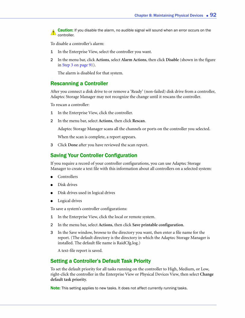
Chapter 8: Maintaining Physical Devices ● 92
Caution: If you disable the alarm, no audible signal will sound when an error occurs on the controller.
To disable a controller’s alarm:
1 In the Enterprise View, select the controller you want.
2 In the menu bar, click Actions, select Alarm Actions, then click Disable (shown in the figure in Step 3 on page 91).
The alarm is disabled for that system.
Rescanning a ControllerAfter you connect a disk drive to or remove a ‘Ready’ (non-failed) disk drive from a controller, Adaptec Storage Manager may not recognize the change until it rescans the controller.
To rescan a controller:
1 In the Enterprise View, click the controller.
2 In the menu bar, select Actions, then click Rescan.
Adaptec Storage Manager scans all the channels or ports on the controller you selected.
When the scan is complete, a report appears.
3 Click Done after you have reviewed the scan report.
Saving Your Controller ConfigurationIf you require a record of your controller configurations, you can use Adaptec Storage Manager to create a text file with this information about all controllers on a selected system:
● Controllers
● Disk drives
● Disk drives used in logical drives
● Logical drives
To save a system’s controller configurations:
1 In the Enterprise View, click the local or remote system.
2 In the menu bar, select Actions, then click Save printable configuration.
3 In the Save window, browse to the directory you want, then enter a file name for the report. (The default directory is the directory in which the Adaptec Storage Manager is installed. The default file name is RaidCfg.log.)
A text-file report is saved.
Setting a Controller’s Default Task PriorityTo set the default priority for all tasks running on the controller to High, Medium, or Low, right-click the controller in the Enterprise View or Physical Devices View, then select Change default task priority.
Note: This setting applies to new tasks. It does not affect currently running tasks.
!

Chapter 8: Maintaining Physical Devices ● 93
Testing and Silencing System and Enclosure AlarmsAdaptec Storage Manager supports an audible alarm which is triggered on the local system when a Warning- or Error-level event (see page 101) occurs on any system in your storage space. Adaptec Storage Manager also supports audible alarms on enclosures.
This section describes how to work with the audible alarms in your storage space:
● For system alarms, see the next section.
● For enclosure alarms, see page 95.
Working with System AlarmsWarning- or Error-level events (see page 101) on a system trigger an audible alarm, a series of beeps which sound every five minutes until the event is resolved.
The alarm is enabled by default, but can be disabled on any system, if required. You can also change the frequency and duration of the alarm.
Note: A system alarm is not the same as a controller alarm. For controller alarm information, see Working with Controllers on page 90.
This section describes how to work with your systems’ audible alarms.
Testing a System’s Alarm
To test the audible alarm to ensure that it’s working on your local system:
1 Ensure that the speakers on your local system aren’t muted.
2 In the Enterprise View, click on your local system.
3 In the menu bar, click Actions, then select Agent actions.
4 Select Alarm actions, then click Test alarm.
The alarm sounds.
5 To stop the test, click OK.
Silencing a System’s Alarm
When a Warning- or Error-level event occurs, you can silence the alarm on your local system while you fix the problem.
To silence the alarm, click the Silence button (shown at right) in the main Adaptec Storage Manager window.
Alternatively, in the menu bar, click Actions, then select Agent actions. Select Alarm actions, then click Test alarm.

Chapter 8: Maintaining Physical Devices ● 94
Changing a System’s Alarm Settings
By default, an audible alarm sounds every five minutes (or 300 seconds) until silenced or until the event is resolved. You can change the frequency of the alarm, if required.
To change alarm settings on a system:
1 In the Enterprise View, select the system.
2 In the tool bar, click Configure, point to the system, then click General Settings .
The Adaptec Storage Manager Agent General Settings window opens for the system you selected. The alarm settings are circled in the next figure.
Note: You can access other utilities in this window, such as the Task Manager (see Scheduling Recurring or Resource-Intensive Jobs on page 81), by clicking their tabs.
3 Edit the alarm settings as required.
Note: You can disable an alarm in this window by deselecting Sound alarm. Alternatively, follow the instructions in Disabling a System’s Alarm on page 95.
The changes take effect immediately.
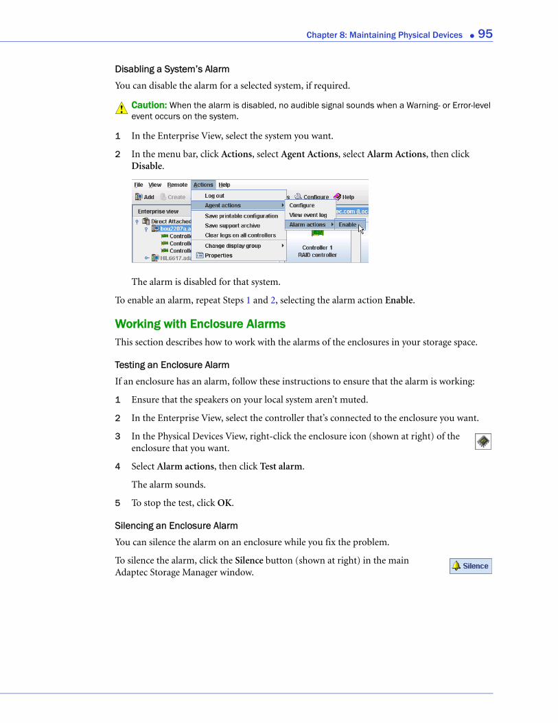
Chapter 8: Maintaining Physical Devices ● 95
Disabling a System’s Alarm
You can disable the alarm for a selected system, if required.
Caution: When the alarm is disabled, no audible signal sounds when a Warning- or Error-level event occurs on the system.
1 In the Enterprise View, select the system you want.
2 In the menu bar, click Actions, select Agent Actions, select Alarm Actions, then click Disable.
The alarm is disabled for that system.
To enable an alarm, repeat Steps 1 and 2, selecting the alarm action Enable.
Working with Enclosure AlarmsThis section describes how to work with the alarms of the enclosures in your storage space.
Testing an Enclosure Alarm
If an enclosure has an alarm, follow these instructions to ensure that the alarm is working:
1 Ensure that the speakers on your local system aren’t muted.
2 In the Enterprise View, select the controller that’s connected to the enclosure you want.
3 In the Physical Devices View, right-click the enclosure icon (shown at right) of the enclosure that you want.
4 Select Alarm actions, then click Test alarm.
The alarm sounds.
5 To stop the test, click OK.
Silencing an Enclosure Alarm
You can silence the alarm on an enclosure while you fix the problem.
To silence the alarm, click the Silence button (shown at right) in the main Adaptec Storage Manager window.
!

Chapter 8: Maintaining Physical Devices ● 96
Disabling an Enclosure Alarm
You can disable the alarm for a selected enclosure, if required.
Caution: If you disable the alarm, no audible signal will sound when an error occurs on the enclosure.
To disable an enclosure’s alarm:
1 In the Enterprise View, select the controller that’s connected to the enclosure you want.
2 In the Physical Devices View, right-click the enclosure icon (shown at right) of the enclosure that you want.
3 Select Alarm actions, then click Disable.
The alarm is disabled for that system.
Updating the Controller BIOS and FirmwareNote: This task is recommended for advanced users only.
Adaptec Storage Manager provides a wizard to help you update the BIOS and firmware for the controllers in your storage space. The ROM Update wizard updates the BIOS and firmware for all controllers of the same type on local and remote systems. You can update one type of controller at a time.
Before You BeginBefore you begin, download the latest firmware images from the Adaptec Web site at www.adaptec.com. Image files typically come in sets of two or more and have a .ufi file extension.
Updating the Controller BIOS and FirmwareTo update the controller firmware:
1 In the Enterprise View, right-click Direct attached storage, then click Update controller images.
The ROM Update wizard opens.
2 Click Next.
!
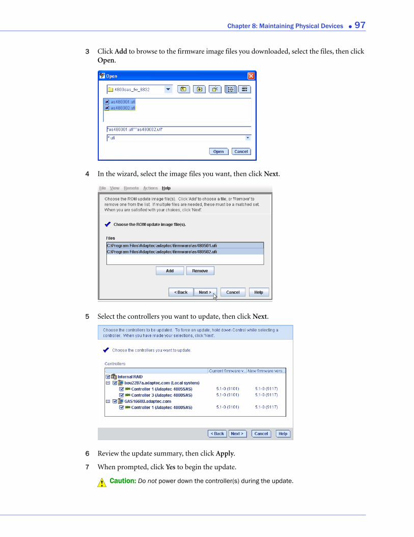
Chapter 8: Maintaining Physical Devices ● 97
3 Click Add to browse to the firmware image files you downloaded, select the files, then click Open.
4 In the wizard, select the image files you want, then click Next.
5 Select the controllers you want to update, then click Next.
6 Review the update summary, then click Apply.
7 When prompted, click Yes to begin the update.
Caution: Do not power down the controller(s) during the update.!

Chapter 8: Maintaining Physical Devices ● 98
8 When the update is complete, click OK. Then, restart the server(s) to activate the new firmware images.

9
Monitoring Status and ActivityIn this chapter...Monitoring Options............................................................................................................. 100
Checking Status from the Main Window............................................................................ 100
Notifying Users by Event Log Message About Status and Activity .................................... 103
Notifying Users by Email About Status and Activity.......................................................... 108
Notifying Users by SNMP Trap About Status and Activity................................................ 113
Nofifying All Users About Status and Activity.................................................................... 114
Changing an Operating System’s Event Log Setting........................................................... 115
Logging Statistics for Remote Analysis................................................................................ 115
This chapter describes how Adaptec Storage Manager helps you monitor your storage space.
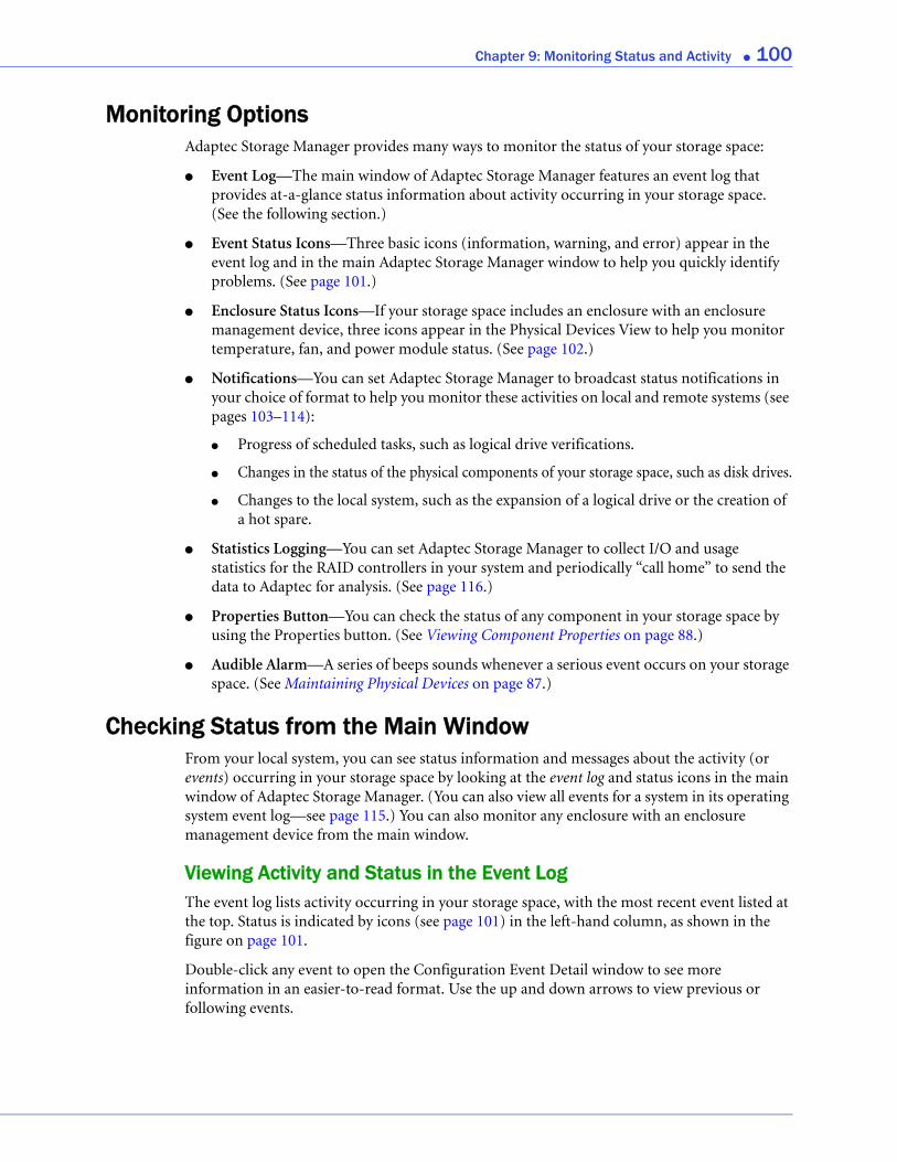
Chapter 9: Monitoring Status and Activity ● 100
Monitoring OptionsAdaptec Storage Manager provides many ways to monitor the status of your storage space:
● Event Log—The main window of Adaptec Storage Manager features an event log that provides at-a-glance status information about activity occurring in your storage space. (See the following section.)
● Event Status Icons—Three basic icons (information, warning, and error) appear in the event log and in the main Adaptec Storage Manager window to help you quickly identify problems. (See page 101.)
● Enclosure Status Icons—If your storage space includes an enclosure with an enclosure management device, three icons appear in the Physical Devices View to help you monitor temperature, fan, and power module status. (See page 102.)
● Notifications—You can set Adaptec Storage Manager to broadcast status notifications in your choice of format to help you monitor these activities on local and remote systems (see pages 103–114):
● Progress of scheduled tasks, such as logical drive verifications.
● Changes in the status of the physical components of your storage space, such as disk drives.
● Changes to the local system, such as the expansion of a logical drive or the creation of a hot spare.
● Statistics Logging—You can set Adaptec Storage Manager to collect I/O and usage statistics for the RAID controllers in your system and periodically “call home” to send the data to Adaptec for analysis. (See page 116.)
● Properties Button—You can check the status of any component in your storage space by using the Properties button. (See Viewing Component Properties on page 88.)
● Audible Alarm—A series of beeps sounds whenever a serious event occurs on your storage space. (See Maintaining Physical Devices on page 87.)
Checking Status from the Main WindowFrom your local system, you can see status information and messages about the activity (or events) occurring in your storage space by looking at the event log and status icons in the main window of Adaptec Storage Manager. (You can also view all events for a system in its operating system event log—see page 115.) You can also monitor any enclosure with an enclosure management device from the main window.
Viewing Activity and Status in the Event LogThe event log lists activity occurring in your storage space, with the most recent event listed at the top. Status is indicated by icons (see page 101) in the left-hand column, as shown in the figure on page 101.
Double-click any event to open the Configuration Event Detail window to see more information in an easier-to-read format. Use the up and down arrows to view previous or following events.
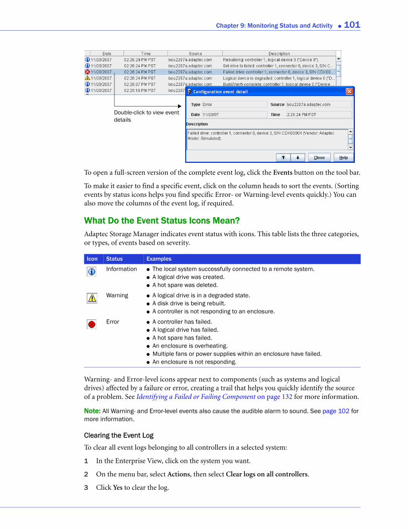
Chapter 9: Monitoring Status and Activity ● 101
To open a full-screen version of the complete event log, click the Events button on the tool bar.
To make it easier to find a specific event, click on the column heads to sort the events. (Sorting events by status icons helps you find specific Error- or Warning-level events quickly.) You can also move the columns of the event log, if required.
What Do the Event Status Icons Mean?Adaptec Storage Manager indicates event status with icons. This table lists the three categories, or types, of events based on severity.
Warning- and Error-level icons appear next to components (such as systems and logical drives) affected by a failure or error, creating a trail that helps you quickly identify the source of a problem. See Identifying a Failed or Failing Component on page 132 for more information.
Note: All Warning- and Error-level events also cause the audible alarm to sound. See page 102 for more information.
Clearing the Event Log
To clear all event logs belonging to all controllers in a selected system:
1 In the Enterprise View, click on the system you want.
2 On the menu bar, select Actions, then select Clear logs on all controllers.
3 Click Yes to clear the log.
Icon Status Examples
Information ● The local system successfully connected to a remote system.● A logical drive was created.● A hot spare was deleted.
Warning ● A logical drive is in a degraded state.● A disk drive is being rebuilt.● A controller is not responding to an enclosure.
Error ● A controller has failed.● A logical drive has failed.● A hot spare has failed.● An enclosure is overheating.● Multiple fans or power supplies within an enclosure have failed.● An enclosure is not responding.
Double-click to view event details

Chapter 9: Monitoring Status and Activity ● 102
Using Enclosure Icons to Monitor Enclosure StatusIf your storage space includes an enclosure with an enclosure management device, such as a SCSI Accessed Fault-Tolerant Enclosure (SAF-TE) processor, Adaptec Storage Manager displays temperature, fan, and power module status in the Physical Device view, as shown in the next figure. The icons change color to indicate status, as described in the table below.
Note: If your enclosure does not have an enclosure management device, the status icons appear but do not indicate status.
Icon Status Examples
Enclosure Fans Normal Fans are working properly.
Warning A fan has failed.
Error Multiple fans have failed.
Enclosure Temperature
Normal Enclosure temperature is normal.
Warning Enclosure temperature is higher than normal.
Error Enclosure is overheating.
Enclosure Power Normal Power supplies are working normally.
Warning One power supply has failed.
Error Multiple power supplies have failed.
Fan StatusTemperature Status
Power Module Status
Enclosure Status Icons
Enclosure Management Device Icon
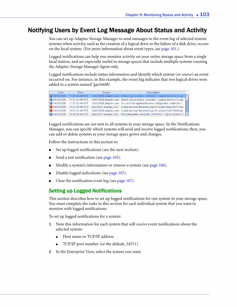
Chapter 9: Monitoring Status and Activity ● 103
Notifying Users by Event Log Message About Status and ActivityYou can set up Adaptec Storage Manager to send messages to the event log of selected remote systems when activity, such as the creation of a logical drive or the failure of a disk drive, occurs on the local system. (For more information about event types, see page 101.)
Logged notifications can help you monitor activity on your entire storage space from a single local station, and are especially useful in storage spaces that include multiple systems running the Adaptec Storage Manager Agent only.
Logged notifications include status information and identify which system (or source) an event occurred on. For instance, in this example, the event log indicates that two logical drives were added to a system named ‘gas1668b’.
Logged notifications are not sent to all systems in your storage space. In the Notifications Manager, you can specify which systems will send and receive logged notifications; then, you can add or delete systems as your storage space grows and changes.
Follow the instructions in this section to:
● Set up logged notifications (see the next section).
● Send a test notification (see page 105).
● Modify a system’s information or remove a system (see page 106).
● Disable logged nofications (see page 107).
● Clear the notification event log (see page 107).
Setting up Logged NotificationsThis section describes how to set up logged notifications for one system in your storage space. You must complete the tasks in this section for each individual system that you want to monitor with logged notifications.
To set up logged notifications for a system:
1 Note this information for each system that will receive event notifications about the selected system:
● Host name or TCP/IP address
● TCP/IP port number (or the default, 34571)
2 In the Enterprise View, select the system you want.
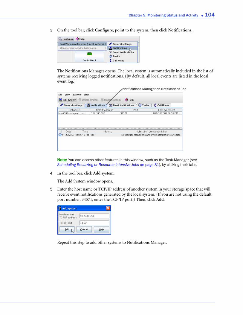
Chapter 9: Monitoring Status and Activity ● 104
3 On the tool bar, click Configure, point to the system, then click Notifications.
The Notifications Manager opens. The local system is automatically included in the list of systems receiving logged notifications. (By default, all local events are listed in the local event log.)
Note: You can access other features in this window, such as the Task Manager (see Scheduling Recurring or Resource-Intensive Jobs on page 81), by clicking their tabs.
4 In the tool bar, click Add system.
The Add System window opens.
5 Enter the host name or TCP/IP address of another system in your storage space that will receive event notifications generated by the local system. (If you are not using the default port number, 34571, enter the TCP/IP port.) Then, click Add.
Repeat this step to add other systems to Notifications Manager.
Notifications Manager on Notifications Tab
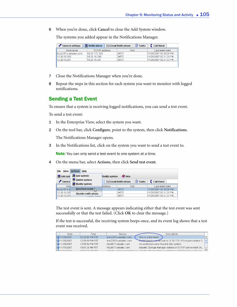
Chapter 9: Monitoring Status and Activity ● 105
6 When you’re done, click Cancel to close the Add System window.
The systems you added appear in the Notifications Manager.
7 Close the Notifications Manager when you’re done.
8 Repeat the steps in this section for each system you want to monitor with logged notifications.
Sending a Test EventTo ensure that a system is receiving logged notifications, you can send a test event.
To send a test event:
1 In the Enterprise View, select the system you want.
2 On the tool bar, click Configure, point to the system, then click Notifications.
The Notifications Manager opens.
3 In the Notifications list, click on the system you want to send a test event to.
Note: You can only send a test event to one system at a time.
4 On the menu bar, select Actions, then click Send test event.
The test event is sent. A message appears indicating either that the test event was sent successfully or that the test failed. (Click OK to clear the message.)
If the test is successful, the receiving system beeps once, and its event log shows that a test event was received.
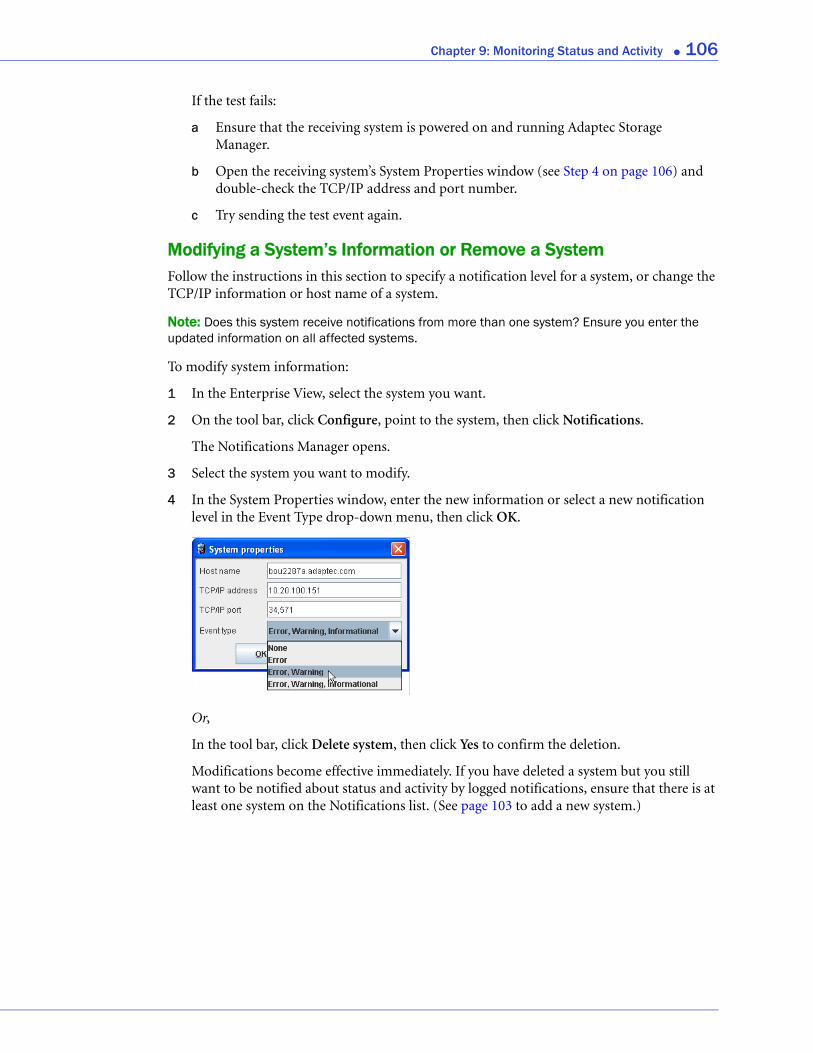
Chapter 9: Monitoring Status and Activity ● 106
If the test fails:
a Ensure that the receiving system is powered on and running Adaptec Storage Manager.
b Open the receiving system’s System Properties window (see Step 4 on page 106) and double-check the TCP/IP address and port number.
c Try sending the test event again.
Modifying a System’s Information or Remove a SystemFollow the instructions in this section to specify a notification level for a system, or change the TCP/IP information or host name of a system.
Note: Does this system receive notifications from more than one system? Ensure you enter the updated information on all affected systems.
To modify system information:
1 In the Enterprise View, select the system you want.
2 On the tool bar, click Configure, point to the system, then click Notifications.
The Notifications Manager opens.
3 Select the system you want to modify.
4 In the System Properties window, enter the new information or select a new notification level in the Event Type drop-down menu, then click OK.
Or,
In the tool bar, click Delete system, then click Yes to confirm the deletion.
Modifications become effective immediately. If you have deleted a system but you still want to be notified about status and activity by logged notifications, ensure that there is at least one system on the Notifications list. (See page 103 to add a new system.)
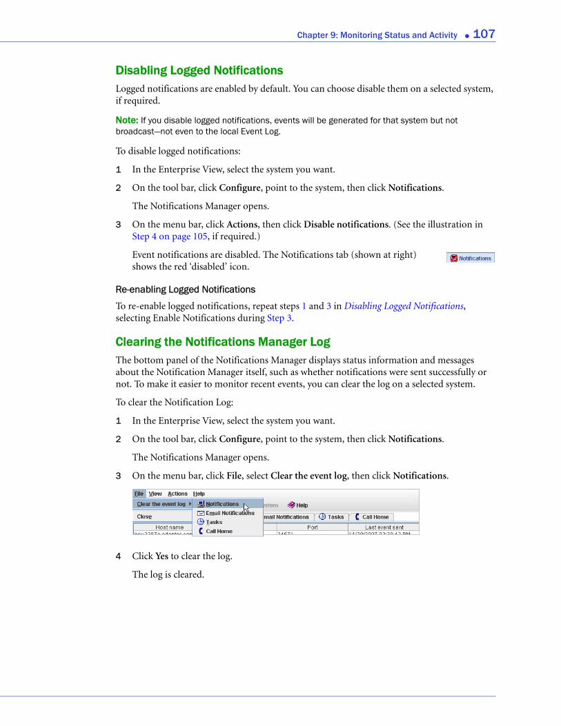
Chapter 9: Monitoring Status and Activity ● 107
Disabling Logged NotificationsLogged notifications are enabled by default. You can choose disable them on a selected system, if required.
Note: If you disable logged notifications, events will be generated for that system but not broadcast—not even to the local Event Log.
To disable logged notifications:
1 In the Enterprise View, select the system you want.
2 On the tool bar, click Configure, point to the system, then click Notifications.
The Notifications Manager opens.
3 On the menu bar, click Actions, then click Disable notifications. (See the illustration in Step 4 on page 105, if required.)
Event notifications are disabled. The Notifications tab (shown at right) shows the red ‘disabled’ icon.
Re-enabling Logged Notifications
To re-enable logged notifications, repeat steps 1 and 3 in Disabling Logged Notifications, selecting Enable Notifications during Step 3.
Clearing the Notifications Manager LogThe bottom panel of the Notifications Manager displays status information and messages about the Notification Manager itself, such as whether notifications were sent successfully or not. To make it easier to monitor recent events, you can clear the log on a selected system.
To clear the Notification Log:
1 In the Enterprise View, select the system you want.
2 On the tool bar, click Configure, point to the system, then click Notifications.
The Notifications Manager opens.
3 On the menu bar, click File, select Clear the event log, then click Notifications.
4 Click Yes to clear the log.
The log is cleared.
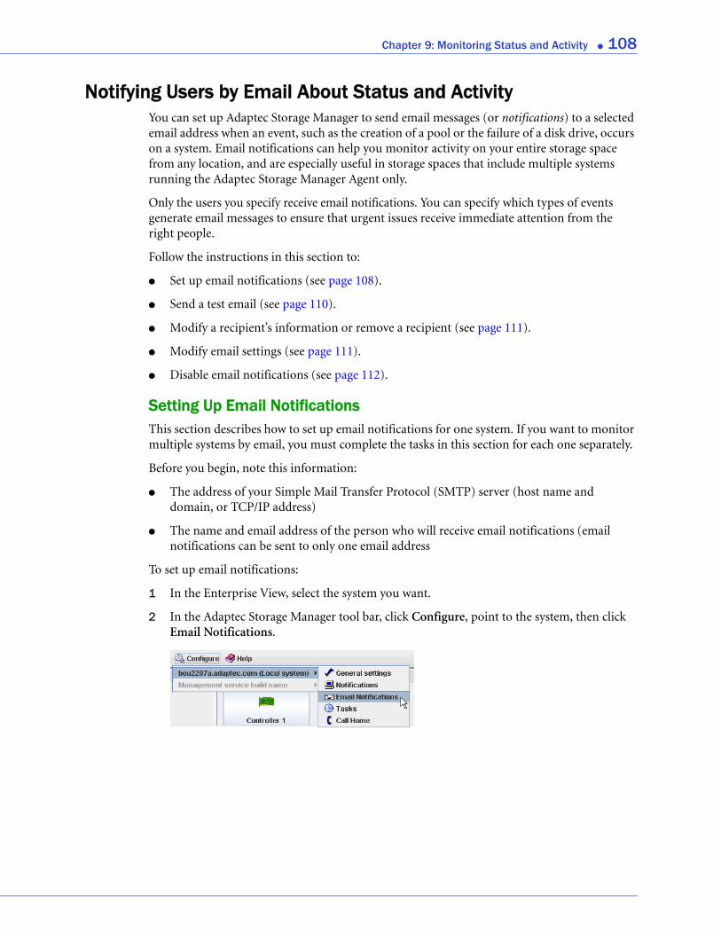
Chapter 9: Monitoring Status and Activity ● 108
Notifying Users by Email About Status and ActivityYou can set up Adaptec Storage Manager to send email messages (or notifications) to a selected email address when an event, such as the creation of a pool or the failure of a disk drive, occurs on a system. Email notifications can help you monitor activity on your entire storage space from any location, and are especially useful in storage spaces that include multiple systems running the Adaptec Storage Manager Agent only.
Only the users you specify receive email notifications. You can specify which types of events generate email messages to ensure that urgent issues receive immediate attention from the right people.
Follow the instructions in this section to:
● Set up email notifications (see page 108).
● Send a test email (see page 110).
● Modify a recipient’s information or remove a recipient (see page 111).
● Modify email settings (see page 111).
● Disable email notifications (see page 112).
Setting Up Email NotificationsThis section describes how to set up email notifications for one system. If you want to monitor multiple systems by email, you must complete the tasks in this section for each one separately.
Before you begin, note this information:
● The address of your Simple Mail Transfer Protocol (SMTP) server (host name and domain, or TCP/IP address)
● The name and email address of the person who will receive email notifications (email notifications can be sent to only one email address
To set up email notifications:
1 In the Enterprise View, select the system you want.
2 In the Adaptec Storage Manager tool bar, click Configure, point to the system, then click Email Notifications.
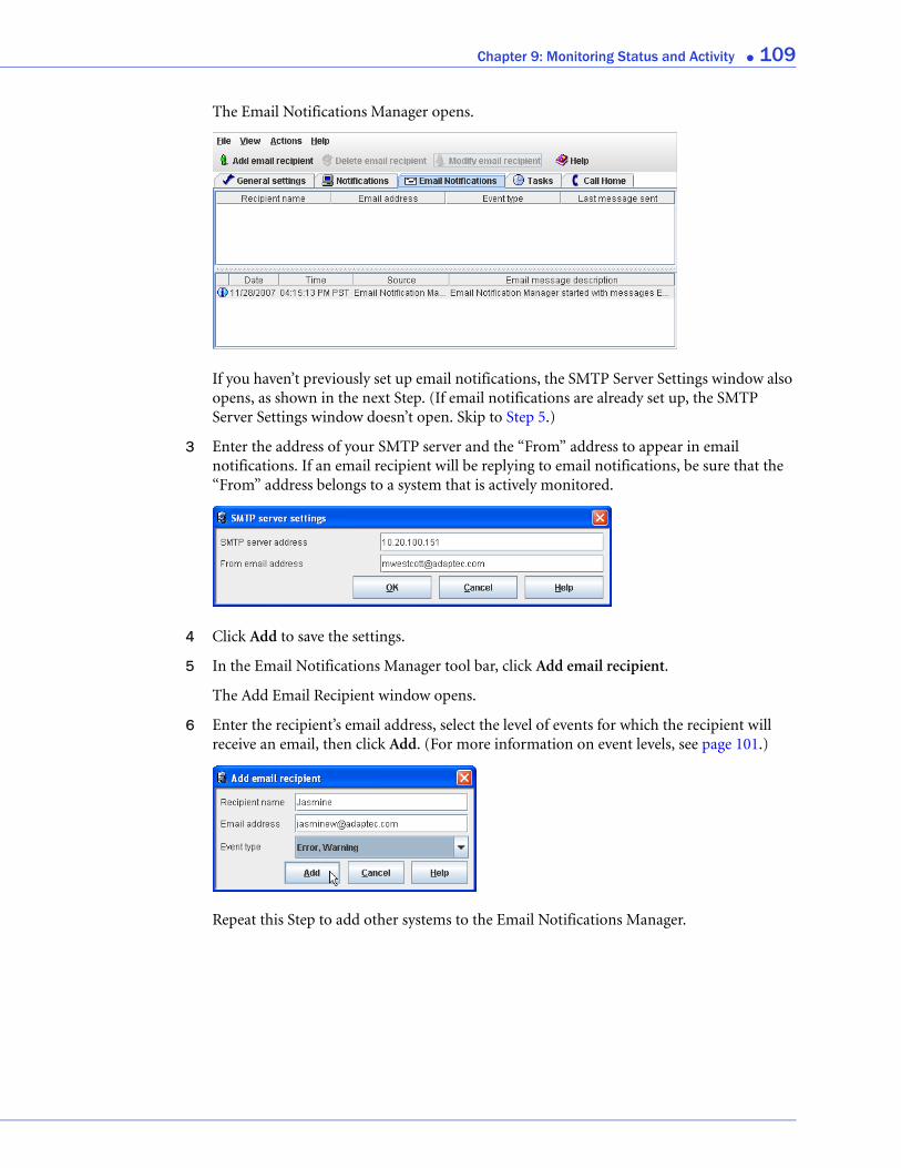
Chapter 9: Monitoring Status and Activity ● 109
The Email Notifications Manager opens.
If you haven’t previously set up email notifications, the SMTP Server Settings window also opens, as shown in the next Step. (If email notifications are already set up, the SMTP Server Settings window doesn’t open. Skip to Step 5.)
3 Enter the address of your SMTP server and the “From” address to appear in email notifications. If an email recipient will be replying to email notifications, be sure that the “From” address belongs to a system that is actively monitored.
4 Click Add to save the settings.
5 In the Email Notifications Manager tool bar, click Add email recipient.
The Add Email Recipient window opens.
6 Enter the recipient’s email address, select the level of events for which the recipient will receive an email, then click Add. (For more information on event levels, see page 101.)
Repeat this Step to add other systems to the Email Notifications Manager.
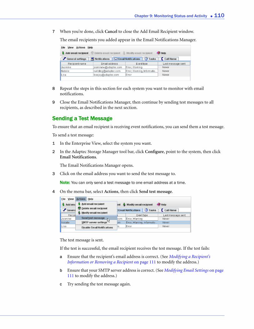
Chapter 9: Monitoring Status and Activity ● 110
7 When you’re done, click Cancel to close the Add Email Recipient window.
The email recipients you added appear in the Email Notifications Manager.
8 Repeat the steps in this section for each system you want to monitor with email notifications.
9 Close the Email Notifications Manager, then continue by sending test messages to all recipients, as described in the next section.
Sending a Test MessageTo ensure that an email recipient is receiving event notifications, you can send them a test message.
To send a test message:
1 In the Enterprise View, select the system you want.
2 In the Adaptec Storage Manager tool bar, click Configure, point to the system, then click Email Notifications.
The Email Notifications Manager opens.
3 Click on the email address you want to send the test message to.
Note: You can only send a test message to one email address at a time.
4 On the menu bar, select Actions, then click Send test message.
The test message is sent.
If the test is successful, the email recipient receives the test message. If the test fails:
a Ensure that the recipient’s email address is correct. (See Modifying a Recipient’s Information or Removing a Recipient on page 111 to modify the address.)
b Ensure that your SMTP server address is correct. (See Modifying Email Settings on page 111 to modify the address.)
c Try sending the test message again.

Chapter 9: Monitoring Status and Activity ● 111
Modifying a Recipient’s Information or Removing a RecipientThis section describes how to modify a recipient’s email address, change the types of event notifications the recipient receives, or stop sending email notifications to a recipient from a selected system.
To modify a recipient’s information:
1 In the Enterprise View, select the system you want.
2 In the Adaptec Storage Manager tool bar, click Configure, point to the system, then click Email Notifications.
The Email Notifications Manager opens.
3 Select the recipient you want, then click Modify email recipient. Change the information as required, then click OK.
Or,
Select the recipient you want, click Delete email recipient, then click Yes to confirm the deletion.
Modifications become effective immediately.
Modifying Email SettingsYou can modify these email settings as your needs change:
● Address of your SMTP server
● ‘From’ address that will appear in email notifications
To modify email settings:
1 In the Enterprise View, select the system you want.
2 In the Adaptec Storage Manager tool bar, click Configure, point to the system, then click Email Notifications.
The Email Notifications Manager opens.
3 On the menu bar, select Actions, then click SMTP server settings.
The SMTP Server Settings window opens.
4 Edit the SMTP server settings as required, then click Add to save the settings.
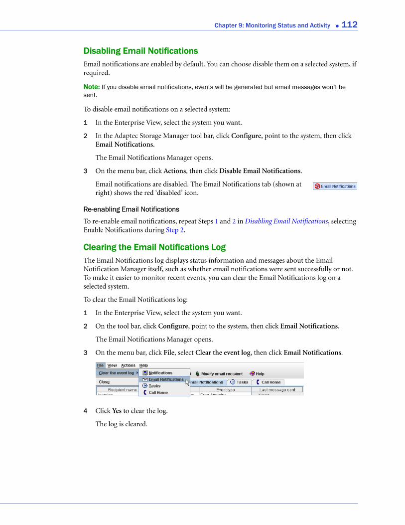
Chapter 9: Monitoring Status and Activity ● 112
Disabling Email NotificationsEmail notifications are enabled by default. You can choose disable them on a selected system, if required.
Note: If you disable email notifications, events will be generated but email messages won’t be sent.
To disable email notifications on a selected system:
1 In the Enterprise View, select the system you want.
2 In the Adaptec Storage Manager tool bar, click Configure, point to the system, then click Email Notifications.
The Email Notifications Manager opens.
3 On the menu bar, click Actions, then click Disable Email Notifications.
Email notifications are disabled. The Email Notifications tab (shown at right) shows the red ‘disabled’ icon.
Re-enabling Email Notifications
To re-enable email notifications, repeat Steps 1 and 2 in Disabling Email Notifications, selecting Enable Notifications during Step 2.
Clearing the Email Notifications Log The Email Notifications log displays status information and messages about the Email Notification Manager itself, such as whether email notifications were sent successfully or not. To make it easier to monitor recent events, you can clear the Email Notifications log on a selected system.
To clear the Email Notifications log:
1 In the Enterprise View, select the system you want.
2 On the tool bar, click Configure, point to the system, then click Email Notifications.
The Email Notifications Manager opens.
3 On the menu bar, click File, select Clear the event log, then click Email Notifications.
4 Click Yes to clear the log.
The log is cleared.

Chapter 9: Monitoring Status and Activity ● 113
Notifying Users by SNMP Trap About Status and Activity Note: Before attempting the tasks in this section, you should be familiar with SNMP traps concepts and technology.
If you are running Windows or Linux, you can use your operating system to monitor Simple Network Management Protocol (SNMP) traps in your storage space, such as disk drive failures and logical drive verifications. One system—typically the system where the GUI is installed—can receive SNMP trap notifications.
To configure SNMP support on:
● Windows, see the next section.
● Linux, see page 114.
Setting Up SNMP Notifications on WindowsNote: Be sure your Windows installation includes SNMP support. By default, Windows 2000 and Windows XP do not install SNMP.
To install and configure SNMP support:
1 From your desktop, open the Windows Computer Management tool, then select Services from the tree.
2 Double-click SNMP Service.
The SNMP Service Properties window opens.
3 Click the Traps tab, then enter the IP address of each system on which you want to enable traps.
4 Click OK.
5 Start the SNMP service.
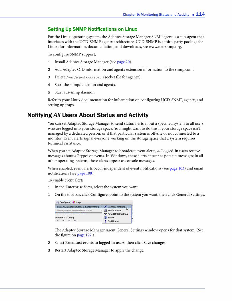
Chapter 9: Monitoring Status and Activity ● 114
Setting Up SNMP Notifications on LinuxFor the Linux operating system, the Adaptec Storage Manager SNMP agent is a sub-agent that interfaces with the UCD-SNMP agentx architecture. UCD-SNMP is a third-party package for Linux; for information, documentation, and downloads, see www.net-snmp.org.
To configure SNMP support:
1 Install Adaptec Storage Manager (see page 20).
2 Add Adaptec OID information and agentx extension information to the snmp.conf.
3 Delete /var/agentx/master (socket file for agentx).
4 Start the snmpd daemon and agentx.
5 Start aus-snmp daemon.
Refer to your Linux documentation for information on configuring UCD-SNMP, agentx, and setting up traps.
Nofifying All Users About Status and ActivityYou can set Adaptec Storage Manager to send status alerts about a specified system to all users who are logged into your storage space. You might want to do this if your storage space isn’t managed by a dedicated person, or if that particular system is off-site or not connected to a monitor. Event alerts signal everyone working on the storage space that a system requires technical assistance.
When you set Adaptec Storage Manager to broadcast event alerts, all logged-in users receive messages about all types of events. In Windows, these alerts appear as pop-up messages; in all other operating systems, these alerts appear as console messages.
When enabled, event alerts occur independent of event notifications (see page 103) and email notifications (see page 108).
To enable event alerts:
1 In the Enterprise View, select the system you want.
1 On the tool bar, click Configure, point to the system you want, then click General Settings.
The Adaptec Storage Manager Agent General Settings window opens for that system. (See the figure on page 127.)
2 Select Broadcast events to logged-in users, then click Save changes.
3 Restart Adaptec Storage Manager to apply the change.
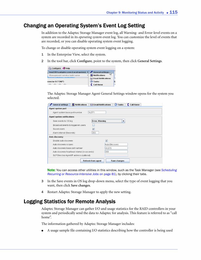
Chapter 9: Monitoring Status and Activity ● 115
Changing an Operating System’s Event Log SettingIn addition to the Adaptec Storage Manager event log, all Warning- and Error-level events on a system are recorded in its operating system event log. You can customize the level of events that are recorded, or you can disable operating system event logging.
To change or disable operating system event logging on a system:
1 In the Enterprise View, select the system.
2 In the tool bar, click Configure, point to the system, then click General Settings.
The Adaptec Storage Manager Agent General Settings window opens for the system you selected.
Note: You can access other utilities in this window, such as the Task Manager (see Scheduling Recurring or Resource-Intensive Jobs on page 81), by clicking their tabs.
3 In the Save events in OS log drop-down menu, select the type of event logging that you want, then click Save changes.
4 Restart Adaptec Storage Manager to apply the new setting.
Logging Statistics for Remote AnalysisAdaptec Storage Manager can gather I/O and usage statistics for the RAID controllers in your system and periodically send the data to Adaptec for analysis. This feature is referred to as “call home”.
The information gathered by Adaptec Storage Manager includes:
● A usage sample file containing I/O statistics describing how the controller is being used

Chapter 9: Monitoring Status and Activity ● 116
● Controller configuration data, such as the number of logical drives, their RAID levels, and size
● Error log files
Note: Adaptec Storage Manager does not gather any proprietary site information when logging statistics for remote analysis. In addition to logging I/O usage statistics, it gathers the same error log files and controller configuration data included in the support archive. See Creating a Support Archive File on page 137 for more information.
Follow the instructions in this section to:
● Set up the statistics logging frequency and reporting interval (see next section).
● Configure proxy server settings (see page 117).
● Send a test message (see page 118).
● Disable call home messages (see page 118).
● Clear the Call Home Manager event log (see page 118).
Setting Up Statistics LoggingThis section describes how to set up the statistics logging frequency and reporting interval. The logging frequency is the rate at which I/O statistics are read from the controller. The reporting interval determines how often the system “calls home” to return the data to Adaptec.
Note: Typically, you enable statistics logging the first time you log in to Adaptec Storage Manager. If you haven’t enabled statistics logging, follow the instructions on page 118, then continue with the instructions below.
To set up statistics logging for a system:
1 In the Enterprise View, select the system you want.
2 On the tool bar, click Configure, point to the system, then click Call Home.
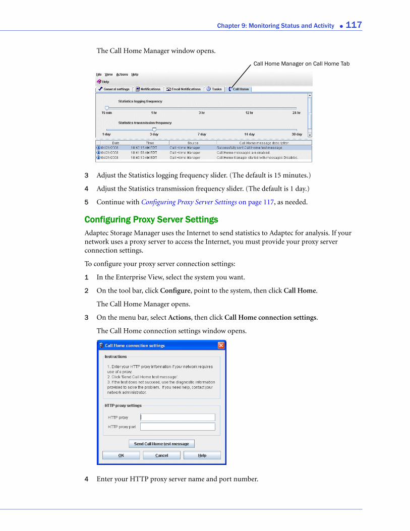
Chapter 9: Monitoring Status and Activity ● 117
The Call Home Manager window opens.
3 Adjust the Statistics logging frequency slider. (The default is 15 minutes.)
4 Adjust the Statistics transmission frequency slider. (The default is 1 day.)
5 Continue with Configuring Proxy Server Settings on page 117, as needed.
Configuring Proxy Server SettingsAdaptec Storage Manager uses the Internet to send statistics to Adaptec for analysis. If your network uses a proxy server to access the Internet, you must provide your proxy server connection settings.
To configure your proxy server connection settings:
1 In the Enterprise View, select the system you want.
2 On the tool bar, click Configure, point to the system, then click Call Home.
The Call Home Manager opens.
3 On the menu bar, select Actions, then click Call Home connection settings.
The Call Home connection settings window opens.
4 Enter your HTTP proxy server name and port number.
Call Home Manager on Call Home Tab
Chapter 9: Monitoring Status and Activity ● 118
5 Click OK.
Sending a Test MessageTo ensure that Adaptec is receiving logged statistics, you can send a test message.
1 In the Enterprise View, select the system you want.
2 On the tool bar, click Configure, point to the system, then click Call Home.
The Call Home Manager opens.
3 On the menu bar, select Actions, then click Call Home connection settings.
The Call Home connection settings window opens.
4 Click Send Call Home test message. A message appears indicating either that the test message was sent successfully or that the test failed.
Click OK to clear the message, then click Cancel to close the Call Home connection settings window.
Note: If the test fails, try opening port 80. If the test continues to fail, your system administrator may need to add the Adaptec Storage Manager Agent to your proxy server’s white list.
Disabling Call Home MessagesIf you prefer not to send usage statistics to Adaptec, you can disable call home messages. Adaptec Storage Manager will continue to collect statistics but not send them to Adaptec for analysis.
To disable call home messages on a selected system:
1 In the Enterprise View, select the system you want.
2 On the tool bar, click Configure, point to the system, then click Call Home.
The Call Home Manager opens.
3 On the menu bar, click Actions, then click Disable Call Home messages.
Call home messages are disabled. The Call Home tab (shown at right) shows the red ‘disabled’ icon.
Re-enabling Call Home Messages
To re-enable call home messages, repeat steps 1 and 2 in Disabling Call Home Messages, selecting Enable Call Home messages during Step 3.
Clearing the Call Home Manager Event LogThe bottom panel of the Call Home Manager displays status information and messages about the Call Home Manager itself, such as whether call home messages were sent successfully or not. To make it easier to monitor recent events, you can clear the log on a selected system.
To clear the Call Home Manager event log:
1 In the Enterprise View, select the system you want.
2 On the tool bar, click Configure, point to the system, then click Call Home.

Chapter 9: Monitoring Status and Activity ● 119
The Call Home Manager window opens.
3 On the menu bar, click File, select Clear the event log, then click Call Home.
4 Click Yes to clear the log.
The log is cleared.
10
Updating and Customizing Adaptec Storage ManagerIn this chapter...
Updating Adaptec Storage Manager.................................................................................... 121
Adding Enhanced Features .................................................................................................. 121
Setting Preferences and Changing Views ............................................................................ 122
Managing Remote Systems .................................................................................................. 123
Working with Display Groups ............................................................................................. 127
This chapter explains how to customize Adaptec Storage Manager as your requirements change and update it as new versions become available.
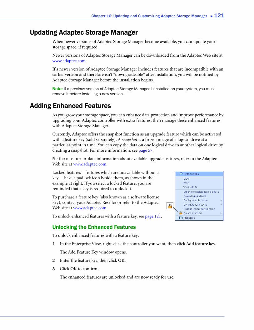
Chapter 10: Updating and Customizing Adaptec Storage Manager ● 121
Updating Adaptec Storage ManagerWhen newer versions of Adaptec Storage Manager become available, you can update your storage space, if required.
Newer versions of Adaptec Storage Manager can be downloaded from the Adaptec Web site at www.adaptec.com.
If a newer version of Adaptec Storage Manager includes features that are incompatible with an earlier version and therefore isn’t “downgradeable” after installation, you will be notified by Adaptec Storage Manager before the installation begins.
Note: If a previous version of Adaptec Storage Manager is installed on your system, you must remove it before installing a new version.
Adding Enhanced FeaturesAs you grow your storage space, you can enhance data protection and improve performance by upgrading your Adaptec controller with extra features, then manage these enhanced features with Adaptec Storage Manager.
Currently, Adaptec offers the snapshot function as an upgrade feature which can be activated with a feature key (sold separately). A snapshot is a frozen image of a logical drive at a particular point in time. You can copy the data on one logical drive to another logical drive by creating a snapshot. For more information, see page 57.
For the most up-to-date information about available upgrade features, refer to the Adaptec Web site at www.adaptec.com.
Locked features—features which are unavailable without a key— have a padlock icon beside them, as shown in the example at right. If you select a locked feature, you are reminded that a key is required to unlock it.
To purchase a feature key (also known as a software license key), contact your Adaptec Reseller or refer to the Adaptec Web site at www.adaptec.com.
To unlock enhanced features with a feature key, see page 121.
Unlocking the Enhanced FeaturesTo unlock enhanced features with a feature key:
1 In the Enterprise View, right-click the controller you want, then click Add feature key.
The Add Feature Key window opens.
2 Enter the feature key, then click OK.
3 Click OK to confirm.
The enhanced features are unlocked and are now ready for use.
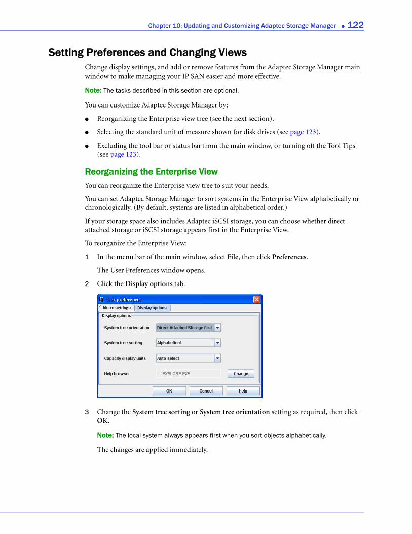
Chapter 10: Updating and Customizing Adaptec Storage Manager ● 122
Setting Preferences and Changing ViewsChange display settings, and add or remove features from the Adaptec Storage Manager main window to make managing your IP SAN easier and more effective.
Note: The tasks described in this section are optional.
You can customize Adaptec Storage Manager by:
● Reorganizing the Enterprise view tree (see the next section).
● Selecting the standard unit of measure shown for disk drives (see page 123).
● Excluding the tool bar or status bar from the main window, or turning off the Tool Tips (see page 123).
Reorganizing the Enterprise ViewYou can reorganize the Enterprise view tree to suit your needs.
You can set Adaptec Storage Manager to sort systems in the Enterprise View alphabetically or chronologically. (By default, systems are listed in alphabetical order.)
If your storage space also includes Adaptec iSCSI storage, you can choose whether direct attached storage or iSCSI storage appears first in the Enterprise View.
To reorganize the Enterprise View:
1 In the menu bar of the main window, select File, then click Preferences.
The User Preferences window opens.
2 Click the Display options tab.
3 Change the System tree sorting or System tree orientation setting as required, then click OK.
Note: The local system always appears first when you sort objects alphabetically.
The changes are applied immediately.
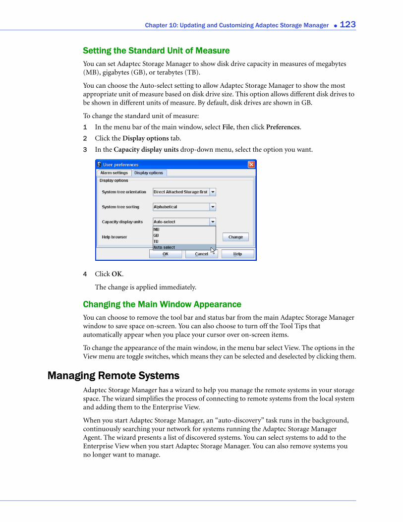
Chapter 10: Updating and Customizing Adaptec Storage Manager ● 123
Setting the Standard Unit of MeasureYou can set Adaptec Storage Manager to show disk drive capacity in measures of megabytes (MB), gigabytes (GB), or terabytes (TB).
You can choose the Auto-select setting to allow Adaptec Storage Manager to show the most appropriate unit of measure based on disk drive size. This option allows different disk drives to be shown in different units of measure. By default, disk drives are shown in GB.
To change the standard unit of measure:
1 In the menu bar of the main window, select File, then click Preferences.
2 Click the Display options tab.
3 In the Capacity display units drop-down menu, select the option you want.
4 Click OK.
The change is applied immediately.
Changing the Main Window AppearanceYou can choose to remove the tool bar and status bar from the main Adaptec Storage Manager window to save space on-screen. You can also choose to turn off the Tool Tips that automatically appear when you place your cursor over on-screen items.
To change the appearance of the main window, in the menu bar select View. The options in the View menu are toggle switches, which means they can be selected and deselected by clicking them.
Managing Remote SystemsAdaptec Storage Manager has a wizard to help you manage the remote systems in your storage space. The wizard simplifies the process of connecting to remote systems from the local system and adding them to the Enterprise View.
When you start Adaptec Storage Manager, an “auto-discovery” task runs in the background, continuously searching your network for systems running the Adaptec Storage Manager Agent. The wizard presents a list of discovered systems. You can select systems to add to the Enterprise View when you start Adaptec Storage Manager. You can also remove systems you no longer want to manage.

Chapter 10: Updating and Customizing Adaptec Storage Manager ● 124
Adding and Removing Remote Systems in the WizardThis section describes how to add or remove discovered systems in the Remote systems wizard. When you add systems, you can set up a group login to connect to all selected systems with a single user name and password. You can also add discovered systems to the Enterprise View without logging in.
To add or remove remote systems in the wizard:
1 In the Enterprise View, select Direct Attached Storage.
2 From the Actions menu, select Manage Remote Systems.
The wizard opens.
3 Select the discovered systems you want to add to the Enterprise View, then click Add. Click Add All to select all discovered systems.
To remove a system from the Enterprise View that you no longer want to manage, select it from the Managed systems list, then click Remove. Click Remove All to remove all managed systems.

Chapter 10: Updating and Customizing Adaptec Storage Manager ● 125
4 Click Next, review the Managed systems summary, then click Apply.
5 If you removed systems that you no longer want to manage, the Removing systems window opens. To continue receiving events from these systems, select Continue to receive events from remote system(s) from the drop-down list; otherwise, select Do not continue to receive events from remote system(s). Then, click OK.
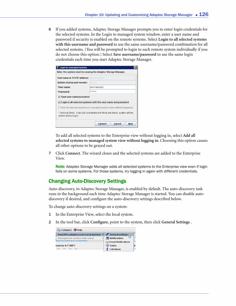
Chapter 10: Updating and Customizing Adaptec Storage Manager ● 126
6 If you added systems, Adaptec Storage Manager prompts you to enter login credentials for the selected systems. In the Login to managed system window, enter a user name and password if security is enabled on the remote systems. Select Login to all selected systems with this username and password to use the same username/password combination for all selected systems. (You will be prompted to login to each remote system individually if you do not choose this option.) Select Save username/password to use the same login credentials each time you start Adaptec Storage Manager.
To add all selected systems to the Enterprise view without logging in, select Add all selected systems to managed system view without logging in. Choosing this option causes all other options to be grayed out.
7 Click Connect. The wizard closes and the selected systems are added to the Enterprise View.
Note: Adaptec Storage Manager adds all selected systems to the Enterprise view even if login fails on some systems. For those systems, try logging in again with different credentials.
Changing Auto-Discovery SettingsAuto-discovery, in Adaptec Storage Manager, is enabled by default. The auto-discovery task runs in the background each time Adaptec Storage Manager is started. You can disable auto-discovery if desired, and configure the auto-discovery settings described below.
To change auto-discovery settings on a system:
1 In the Enterprise View, select the local system.
2 In the tool bar, click Configure, point to the system, then click General Settings .
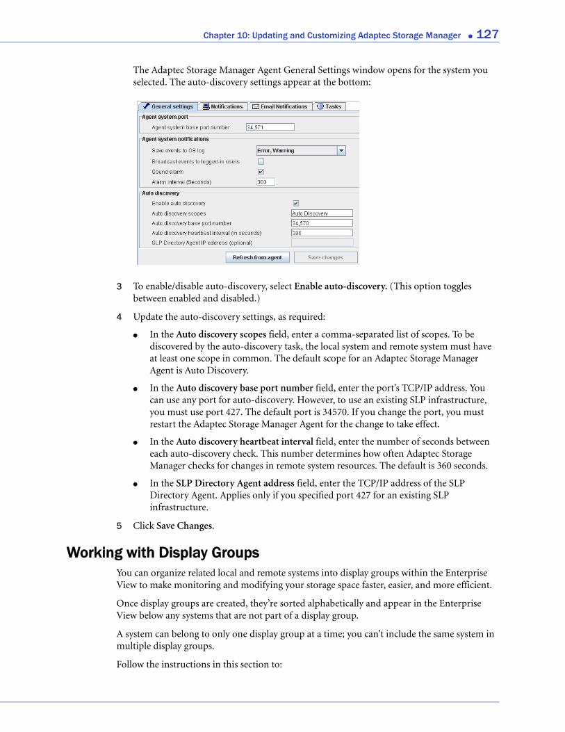
Chapter 10: Updating and Customizing Adaptec Storage Manager ● 127
The Adaptec Storage Manager Agent General Settings window opens for the system you selected. The auto-discovery settings appear at the bottom:
3 To enable/disable auto-discovery, select Enable auto-discovery. (This option toggles between enabled and disabled.)
4 Update the auto-discovery settings, as required:
● In the Auto discovery scopes field, enter a comma-separated list of scopes. To be discovered by the auto-discovery task, the local system and remote system must have at least one scope in common. The default scope for an Adaptec Storage Manager Agent is Auto Discovery.
● In the Auto discovery base port number field, enter the port’s TCP/IP address. You can use any port for auto-discovery. However, to use an existing SLP infrastructure, you must use port 427. The default port is 34570. If you change the port, you must restart the Adaptec Storage Manager Agent for the change to take effect.
● In the Auto discovery heartbeat interval field, enter the number of seconds between each auto-discovery check. This number determines how often Adaptec Storage Manager checks for changes in remote system resources. The default is 360 seconds.
● In the SLP Directory Agent address field, enter the TCP/IP address of the SLP Directory Agent. Applies only if you specified port 427 for an existing SLP infrastructure.
5 Click Save Changes.
Working with Display GroupsYou can organize related local and remote systems into display groups within the Enterprise View to make monitoring and modifying your storage space faster, easier, and more efficient.
Once display groups are created, they’re sorted alphabetically and appear in the Enterprise View below any systems that are not part of a display group.
A system can belong to only one display group at a time; you can’t include the same system in multiple display groups.
Follow the instructions in this section to:
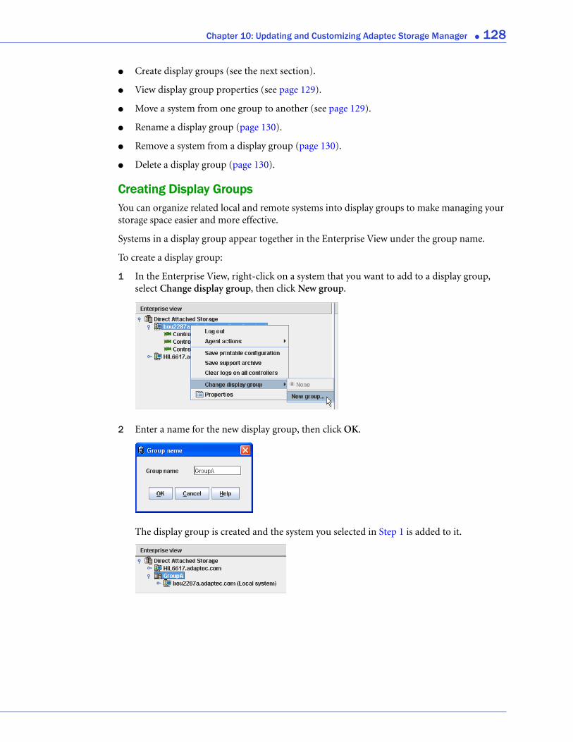
Chapter 10: Updating and Customizing Adaptec Storage Manager ● 128
● Create display groups (see the next section).
● View display group properties (see page 129).
● Move a system from one group to another (see page 129).
● Rename a display group (page 130).
● Remove a system from a display group (page 130).
● Delete a display group (page 130).
Creating Display GroupsYou can organize related local and remote systems into display groups to make managing your storage space easier and more effective.
Systems in a display group appear together in the Enterprise View under the group name.
To create a display group:
1 In the Enterprise View, right-click on a system that you want to add to a display group, select Change display group, then click New group.
2 Enter a name for the new display group, then click OK.
The display group is created and the system you selected in Step 1 is added to it.

Chapter 10: Updating and Customizing Adaptec Storage Manager ● 129
3 To add another system to the display group, repeat right-click on that system in the Enterprise View, select Change display group, then click the display group name.
The system is added to the display group.
Note: A system can belong to only one display group at a time; you can’t include the same system in multiple display groups.
Viewing Display Group StatusTo quickly view the status of systems within a display group, you can open the display group Properties window.
In the Enterprise View, right-click on the display group, then click Properties. The Properties window opens for that display group, summarizing the status of the systems that belong to that group.
Moving a System from One Display Group to AnotherTo move a system from one display group to another:
1 In the Enterprise View, right-click the system you want to move.
2 Select Change display group, then click the name of the display group you want.
The system moves to its new display group.
Chapter 10: Updating and Customizing Adaptec Storage Manager ● 130
Renaming a Display GroupYou can make managing your storage space easier and more efficient by giving your display groups meaningful names. To rename a display group:
1 In the Enterprise View, right-click on the display group, then click Rename display group.
2 Enter a new name for the display group, then click OK.
The Enterprise View shows the new name of the display group.
Removing a System from a Display GroupTo remove a system from a display group:
1 In the Enterprise View, right-click the system you want to remove.
2 Select Change display group, then click None.
The system is removed from the display group.
Note: Systems that are not part of display groups are listed at the top of the Enterprise View, above any display groups.
Deleting a Display GroupIf required, you can delete a display group. When you delete the display group, the systems that belonged to it are listed at the top of the Enterprise View, above any remaining display groups.
To delete a display group:
1 In the Enterprise View, right-click on the display group.
2 Click Delete display group.
The display group is deleted and the systems that belonged to it are no longer grouped together in the Enterprise View.
Chapter 11: Solving Problems ● 131
11Solving Problems
In this chapter...
General Troubleshooting Tips ............................................................................................. 132
Identifying a Failed or Failing Component......................................................................... 132
Stopping the Creation of a New Logical Drive ................................................................... 133
Recovering from a Disk Drive Failure ................................................................................. 133
Rebuilding Logical Drives .................................................................................................... 136
Solving Notification Problems............................................................................................. 137
Creating a Support Archive File........................................................................................... 137
Understanding Error and Warning Messages ..................................................................... 138
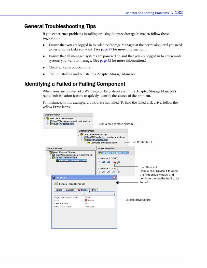
Chapter 11: Solving Problems ● 132
General Troubleshooting TipsIf you experience problems installing or using Adaptec Storage Manager, follow these suggestions:
● Ensure that you are logged in to Adaptec Storage Manager at the permission level you need to perform the tasks you want. (See page 27 for more information.)
● Ensure that all managed systems are powered on and that you are logged in to any remote systems you want to manage. (See page 32 for more information.)
● Check all cable connections.
● Try uninstalling and reinstalling Adaptec Storage Manager.
Identifying a Failed or Failing ComponentWhen your are notified of a Warning- or Error-level event, use Adaptec Storage Manager’s rapid fault isolation feature to quickly identify the source of the problem.
For instance, in this example, a disk drive has failed. To find the failed disk drive, follow the yellow Error icons:
Error is on a remote system...
...on Controller 1...
...on Device 1. Double-click Device 1 to open the Properties window and continue tracing the fault to its source...
...a disk drive failure.

Chapter 11: Solving Problems ● 133
Stopping the Creation of a New Logical DriveTo stop the creation of a new logical drive, right-click on the magnifying glass icon, then select Stop current task. You can also change the priority of the build task to High, Medium, or Low by selecting Change background task priority from the same right-click menu.
Recovering from a Disk Drive FailureWhen a disk drive fails for any reason, it is represented in Adaptec Storage Manager with a red X, as shown at right.
This section explains how to recover when a disk drive fails:
● If the logical drive was protected by a hot spare (see the following section).
● If the logical drive was not protected by a hot spare (see page 134).
● If there is a disk drive failure in more than one logical drive simultaneously (see page 134).
● If it is a RAID 0 logical drive (see page 134).
● If multiple disk drives fail within the same logical drive (see page 135).
● If you want to force a logical drive with multiple drive failures back online (see page 136).
Failed Disk Drive Protected by a Hot SpareWhen a logical drive is protected by a hot spare, if a disk drive in that logical drive fails the hot spare is automatically incorporated into the logical drive and takes over for the failed drive.
For instance, when a disk drive fails in the RAID 5 logical drive shown in the next example, the logical drive is automatically rebuilt (its data is reconstructed) using the hot spare in place of the failed drive. You can access the logical drive while it’s rebuilding.
...and logical drive is rebuilt with hot spare.
...Disk drive showsFailed status...
Hot spare takes over...
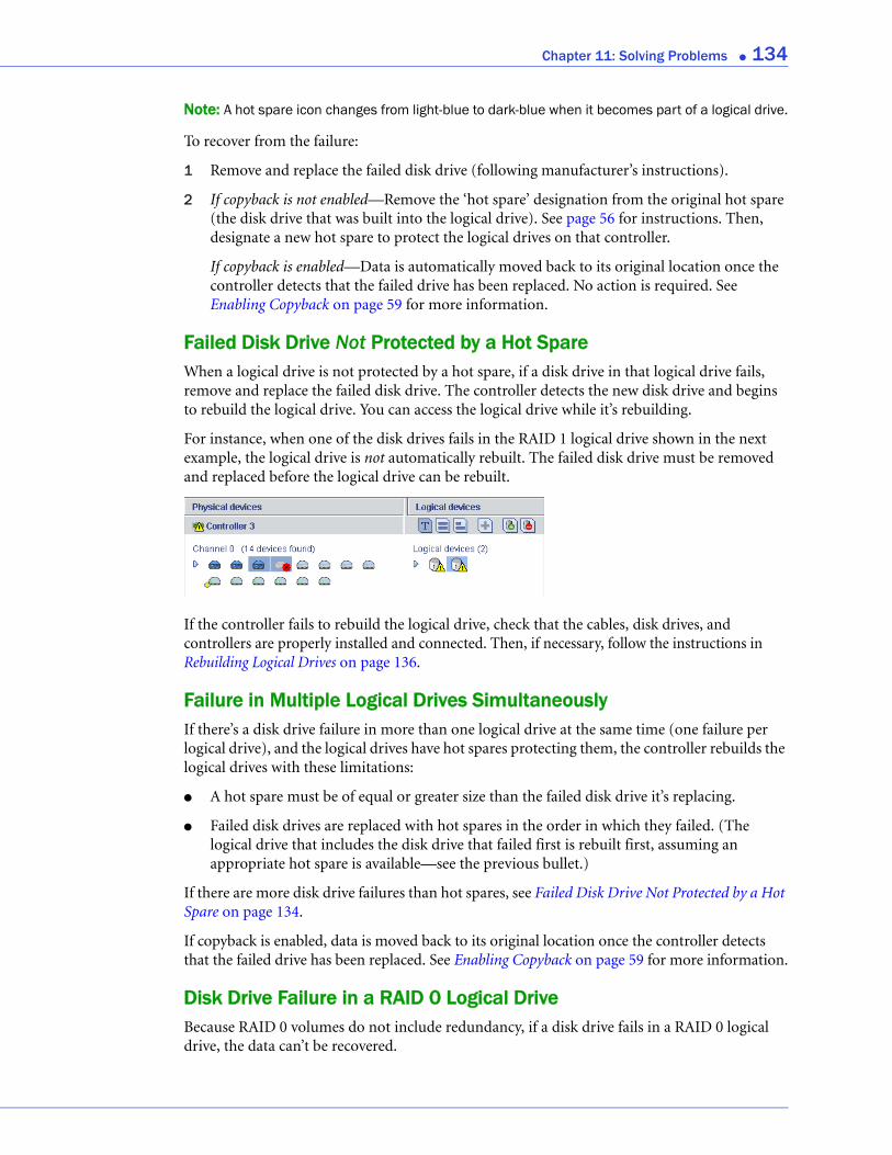
Chapter 11: Solving Problems ● 134
Note: A hot spare icon changes from light-blue to dark-blue when it becomes part of a logical drive.
To recover from the failure:
1 Remove and replace the failed disk drive (following manufacturer’s instructions).
2 If copyback is not enabled—Remove the ‘hot spare’ designation from the original hot spare (the disk drive that was built into the logical drive). See page 56 for instructions. Then, designate a new hot spare to protect the logical drives on that controller.
If copyback is enabled—Data is automatically moved back to its original location once the controller detects that the failed drive has been replaced. No action is required. See Enabling Copyback on page 59 for more information.
Failed Disk Drive Not Protected by a Hot SpareWhen a logical drive is not protected by a hot spare, if a disk drive in that logical drive fails, remove and replace the failed disk drive. The controller detects the new disk drive and begins to rebuild the logical drive. You can access the logical drive while it’s rebuilding.
For instance, when one of the disk drives fails in the RAID 1 logical drive shown in the next example, the logical drive is not automatically rebuilt. The failed disk drive must be removed and replaced before the logical drive can be rebuilt.
If the controller fails to rebuild the logical drive, check that the cables, disk drives, and controllers are properly installed and connected. Then, if necessary, follow the instructions in Rebuilding Logical Drives on page 136.
Failure in Multiple Logical Drives SimultaneouslyIf there’s a disk drive failure in more than one logical drive at the same time (one failure per logical drive), and the logical drives have hot spares protecting them, the controller rebuilds the logical drives with these limitations:
● A hot spare must be of equal or greater size than the failed disk drive it’s replacing.
● Failed disk drives are replaced with hot spares in the order in which they failed. (The logical drive that includes the disk drive that failed first is rebuilt first, assuming an appropriate hot spare is available—see the previous bullet.)
If there are more disk drive failures than hot spares, see Failed Disk Drive Not Protected by a Hot Spare on page 134.
If copyback is enabled, data is moved back to its original location once the controller detects that the failed drive has been replaced. See Enabling Copyback on page 59 for more information.
Disk Drive Failure in a RAID 0 Logical DriveBecause RAID 0 volumes do not include redundancy, if a disk drive fails in a RAID 0 logical drive, the data can’t be recovered.
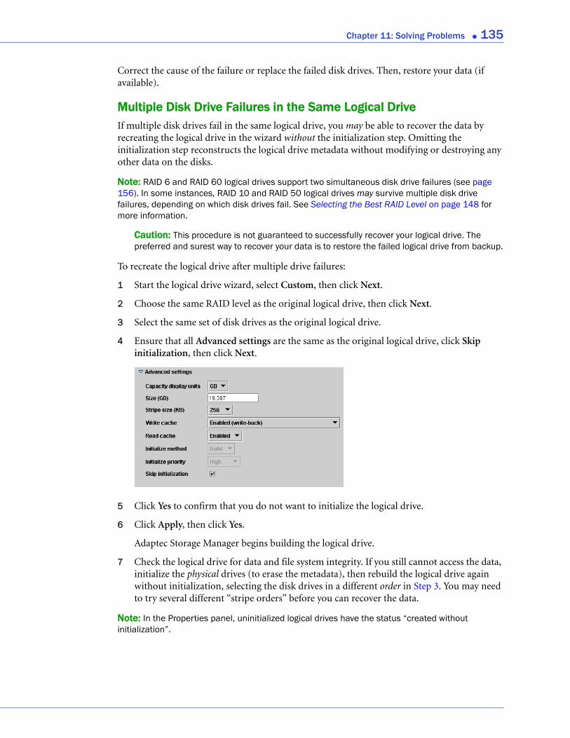
Chapter 11: Solving Problems ● 135
Correct the cause of the failure or replace the failed disk drives. Then, restore your data (if available).
Multiple Disk Drive Failures in the Same Logical DriveIf multiple disk drives fail in the same logical drive, you may be able to recover the data by recreating the logical drive in the wizard without the initialization step. Omitting the initialization step reconstructs the logical drive metadata without modifying or destroying any other data on the disks.
Note: RAID 6 and RAID 60 logical drives support two simultaneous disk drive failures (see page 156). In some instances, RAID 10 and RAID 50 logical drives may survive multiple disk drive failures, depending on which disk drives fail. See Selecting the Best RAID Level on page 148 for more information.
Caution: This procedure is not guaranteed to successfully recover your logical drive. The preferred and surest way to recover your data is to restore the failed logical drive from backup.
To recreate the logical drive after multiple drive failures:
1 Start the logical drive wizard, select Custom, then click Next.
2 Choose the same RAID level as the original logical drive, then click Next.
3 Select the same set of disk drives as the original logical drive.
4 Ensure that all Advanced settings are the same as the original logical drive, click Skip initialization, then click Next.
5 Click Yes to confirm that you do not want to initialize the logical drive.
6 Click Apply, then click Yes.
Adaptec Storage Manager begins building the logical drive.
7 Check the logical drive for data and file system integrity. If you still cannot access the data, initialize the physical drives (to erase the metadata), then rebuild the logical drive again without initialization, selecting the disk drives in a different order in Step 3. You may need to try several different “stripe orders” before you can recover the data.
Note: In the Properties panel, uninitialized logical drives have the status “created without initialization”.
Chapter 11: Solving Problems ● 136
Forcing a Logical Drive with Multiple Drive Failures Back OnlineIf multiple disk drives fail in the same logical drive, you may be able to recover the data by forcing the logical drive back online. For instance, if two drives fail in a RAID 5, forcing it online may allow you to access the data, depending on which disk drives failed.
Caution: This procedure is not guaranteed to successfully recover your logical drive. The preferred and surest way to recover your data is to restore the failed logical drive from backup. Before using this procedure, check all connectors (cables, power, and so on ), then try restoring the logical drive by performing a bus rescan or restarting the server.
To force a logical drive online:
1 In the Logical Devices View, select the failed logical drive.
2 In the menu bar, select Actions, then click Force online.
3 Click Yes to confirm, then click OK.
4 If Adaptec Storage Manager successfully forces the logical drive online, check it for data and file system integrity. If some disks are still missing from the logical drive, reinsert or replace them and allow Adaptec Storage Manager to rebuild the logical drive. Then verify that drive status has returned to Optimal.
Note: If the operation fails, follow the on-screen prompts to try the Advanced options for forcing the logical drive online. Only expert users should try the Advanced options.
Removing a Failed Disk Drive’s IconNote: You can only complete this task on disk drives that are not included in any logical drive.
When a disk drive fails, it may still appear in Adaptec Storage Manager although it is no longer available. To see an accurate representation of your storage space and make it easier to monitor your disk drives, you can remove a failed disk drive from the Physical Devices View.
In the Physical Devices View, right-click the failed disk drive, then click Remove failed drive.
Rebuilding Logical DrivesA hot-swap rebuild occurs when a controller detects that a failed disk drive in a logical drive has been removed and then reinserted.
To start a hot-swap rebuild:
1 Following manufacturer’s instructions, gently pull the failed disk drive from the server without fully removing it, then wait for it to spin down fully before continuing.
2 If there is nothing wrong with the disk drive, reinstall it, following manufacturer’s instructions.
If necessary, replace the failed disk drive with a new disk drive of equal or larger size.
3 The controller detects the reinserted (or new) disk drive and begins to rebuild the logical drive.
Chapter 11: Solving Problems ● 137
Solving Notification ProblemsTo test notifications on your storage space, you can send test events or emails to ensure that they’re being received properly.
If your test event fails:
1 Ensure that the remote system is powered on and running Adaptec Storage Manager.
2 Open the remote system’s System Properties window (see Step 4 on page 106) and double-check the TCP/IP address and port number.
3 Try sending the test event again.
If your test email fails:
1 Ensure that the recipient’s email address is correct. (See Modifying a Recipient’s Information or Removing a Recipient on page 111 to modify the address.)
2 Ensure that your SMTP server address is correct. (See Modifying Email Settings on page 111 to modify the address.)
3 Try sending the test message again.
Creating a Support Archive FileYour Adaptec Storage Manager service representative might ask you to create a configuration and status information archive file to help diagnose a problem with your system.
To create the archive file:
1 In the Enterprise View, click the local or remote system on which the problem is occurring.
2 In the menu bar, select Actions, then click Save support archive.
3 Enter a name for the archive file or accept the default name, then click Save.
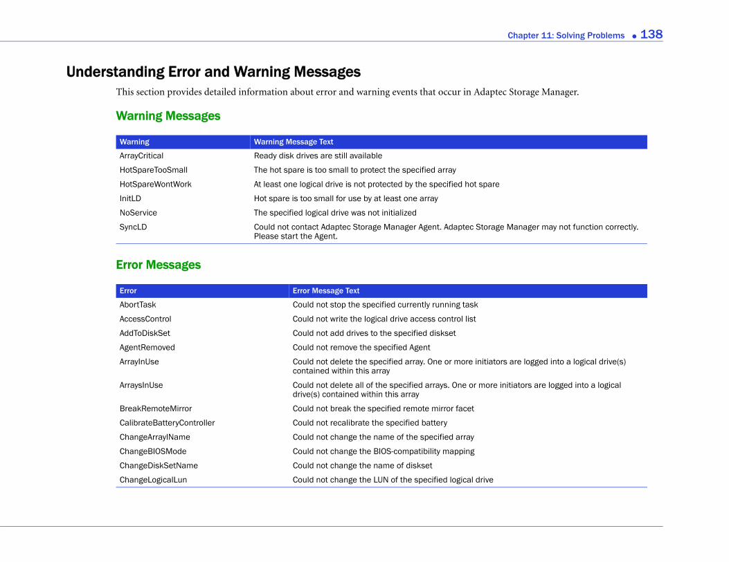
Chapter 11: Solving Problems ● 138
Storage Manager.
Manager may not function correctly.
are logged into a logical drive(s)
itiators are logged into a logical
Understanding Error and Warning MessagesThis section provides detailed information about error and warning events that occur in Adaptec
Warning Messages
Error Messages
Warning Warning Message Text
ArrayCritical Ready disk drives are still available
HotSpareTooSmall The hot spare is too small to protect the specified array
HotSpareWontWork At least one logical drive is not protected by the specified hot spare
InitLD Hot spare is too small for use by at least one array
NoService The specified logical drive was not initialized
SyncLD Could not contact Adaptec Storage Manager Agent. Adaptec Storage Please start the Agent.
Error Error Message Text
AbortTask Could not stop the specified currently running task
AccessControl Could not write the logical drive access control list
AddToDiskSet Could not add drives to the specified diskset
AgentRemoved Could not remove the specified Agent
ArrayInUse Could not delete the specified array. One or more initiatorscontained within this array
ArraysInUse Could not delete all of the specified arrays. One or more indrive(s) contained within this array
BreakRemoteMirror Could not break the specified remote mirror facet
CalibrateBatteryController Could not recalibrate the specified battery
ChangeArraylName Could not change the name of the specified array
ChangeBIOSMode Could not change the BIOS-compatibility mapping
ChangeDiskSetName Could not change the name of diskset
ChangeLogicalLun Could not change the LUN of the specified logical drive
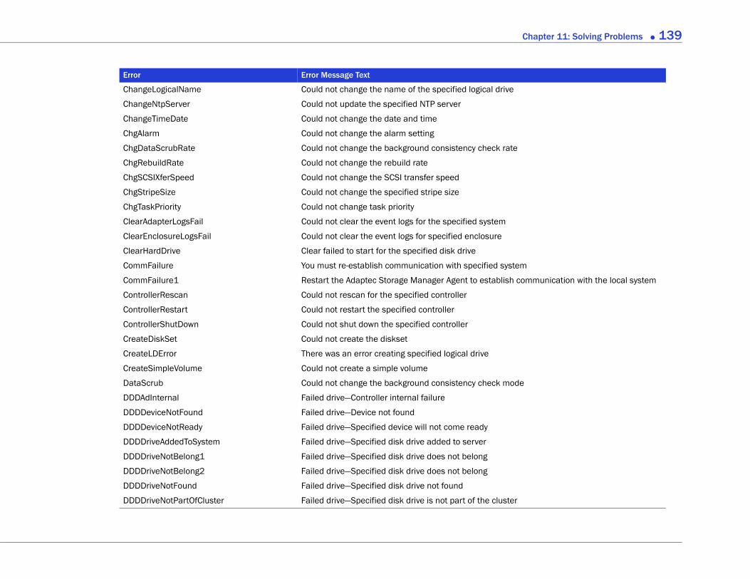
Chapter 11: Solving Problems ● 139
ommunication with the local system
ChangeLogicalName Could not change the name of the specified logical drive
ChangeNtpServer Could not update the specified NTP server
ChangeTimeDate Could not change the date and time
ChgAlarm Could not change the alarm setting
ChgDataScrubRate Could not change the background consistency check rate
ChgRebuildRate Could not change the rebuild rate
ChgSCSIXferSpeed Could not change the SCSI transfer speed
ChgStripeSize Could not change the specified stripe size
ChgTaskPriority Could not change task priority
ClearAdapterLogsFail Could not clear the event logs for the specified system
ClearEnclosureLogsFail Could not clear the event logs for specified enclosure
ClearHardDrive Clear failed to start for the specified disk drive
CommFailure You must re-establish communication with specified system
CommFailure1 Restart the Adaptec Storage Manager Agent to establish c
ControllerRescan Could not rescan for the specified controller
ControllerRestart Could not restart the specified controller
ControllerShutDown Could not shut down the specified controller
CreateDiskSet Could not create the diskset
CreateLDError There was an error creating specified logical drive
CreateSimpleVolume Could not create a simple volume
DataScrub Could not change the background consistency check mode
DDDAdInternal Failed drive—Controller internal failure
DDDDeviceNotFound Failed drive—Device not found
DDDDeviceNotReady Failed drive—Specified device will not come ready
DDDDriveAddedToSystem Failed drive—Specified disk drive added to server
DDDDriveNotBelong1 Failed drive—Specified disk drive does not belong
DDDDriveNotBelong2 Failed drive—Specified disk drive does not belong
DDDDriveNotFound Failed drive—Specified disk drive not found
DDDDriveNotPartOfCluster Failed drive—Specified disk drive is not part of the cluster
Error Error Message Text
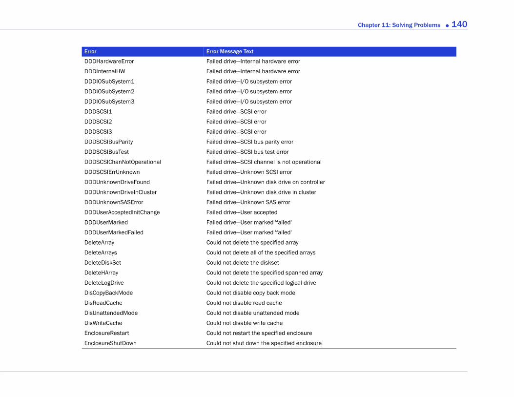
Chapter 11: Solving Problems ● 140
DDDHardwareError Failed drive—Internal hardware error
DDDInternalHW Failed drive—Internal hardware error
DDDIOSubSystem1 Failed drive—I/O subsystem error
DDDIOSubSystem2 Failed drive—I/O subsystem error
DDDIOSubSystem3 Failed drive—I/O subsystem error
DDDSCSI1 Failed drive—SCSI error
DDDSCSI2 Failed drive—SCSI error
DDDSCSI3 Failed drive—SCSI error
DDDSCSIBusParity Failed drive—SCSI bus parity error
DDDSCSIBusTest Failed drive—SCSI bus test error
DDDSCSIChanNotOperational Failed drive—SCSI channel is not operational
DDDSCSIErrUnknown Failed drive—Unknown SCSI error
DDDUnknownDriveFound Failed drive—Unknown disk drive on controller
DDDUnknownDriveInCluster Failed drive—Unknown disk drive in cluster
DDDUnknownSASError Failed drive—Unknown SAS error
DDDUserAcceptedInitChange Failed drive—User accepted
DDDUserMarked Failed drive—User marked 'failed'
DDDUserMarkedFailed Failed drive—User marked 'failed'
DeleteArray Could not delete the specified array
DeleteArrays Could not delete all of the specified arrays
DeleteDiskSet Could not delete the diskset
DeleteHArray Could not delete the specified spanned array
DeleteLogDrive Could not delete the specified logical drive
DisCopyBackMode Could not disable copy back mode
DisReadCache Could not disable read cache
DisUnattendedMode Could not disable unattended mode
DisWriteCache Could not disable write cache
EnclosureRestart Could not restart the specified enclosure
EnclosureShutDown Could not shut down the specified enclosure
Error Error Message Text
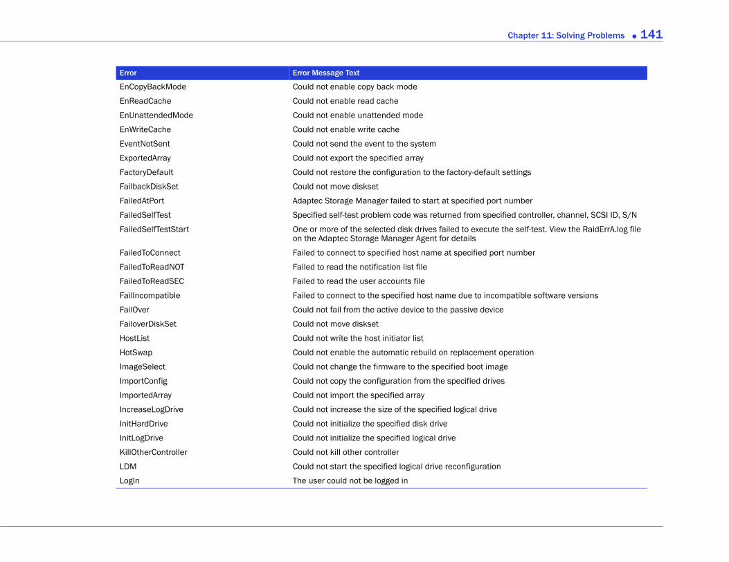
Chapter 11: Solving Problems ● 141
ettings
umber
ed controller, channel, SCSI ID, S/N
e self-test. View the RaidErrA.log file
number
patible software versions
eration
EnCopyBackMode Could not enable copy back mode
EnReadCache Could not enable read cache
EnUnattendedMode Could not enable unattended mode
EnWriteCache Could not enable write cache
EventNotSent Could not send the event to the system
ExportedArray Could not export the specified array
FactoryDefault Could not restore the configuration to the factory-default s
FailbackDiskSet Could not move diskset
FailedAtPort Adaptec Storage Manager failed to start at specified port n
FailedSelfTest Specified self-test problem code was returned from specifi
FailedSelfTestStart One or more of the selected disk drives failed to execute thon the Adaptec Storage Manager Agent for details
FailedToConnect Failed to connect to specified host name at specified port
FailedToReadNOT Failed to read the notification list file
FailedToReadSEC Failed to read the user accounts file
FailIncompatible Failed to connect to the specified host name due to incom
FailOver Could not fail from the active device to the passive device
FailoverDiskSet Could not move diskset
HostList Could not write the host initiator list
HotSwap Could not enable the automatic rebuild on replacement op
ImageSelect Could not change the firmware to the specified boot image
ImportConfig Could not copy the configuration from the specified drives
ImportedArray Could not import the specified array
IncreaseLogDrive Could not increase the size of the specified logical drive
InitHardDrive Could not initialize the specified disk drive
InitLogDrive Could not initialize the specified logical drive
KillOtherController Could not kill other controller
LDM Could not start the specified logical drive reconfiguration
LogIn The user could not be logged in
Error Error Message Text
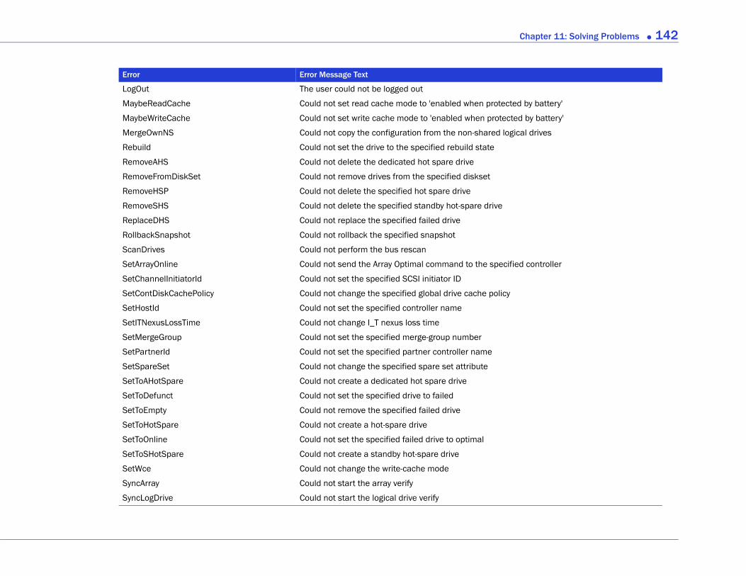
Chapter 11: Solving Problems ● 142
by battery'
d by battery'
al drives
d controller
LogOut The user could not be logged out
MaybeReadCache Could not set read cache mode to 'enabled when protected
MaybeWriteCache Could not set write cache mode to 'enabled when protecte
MergeOwnNS Could not copy the configuration from the non-shared logic
Rebuild Could not set the drive to the specified rebuild state
RemoveAHS Could not delete the dedicated hot spare drive
RemoveFromDiskSet Could not remove drives from the specified diskset
RemoveHSP Could not delete the specified hot spare drive
RemoveSHS Could not delete the specified standby hot-spare drive
ReplaceDHS Could not replace the specified failed drive
RollbackSnapshot Could not rollback the specified snapshot
ScanDrives Could not perform the bus rescan
SetArrayOnline Could not send the Array Optimal command to the specifie
SetChannelInitiatorId Could not set the specified SCSI initiator ID
SetContDiskCachePolicy Could not change the specified global drive cache policy
SetHostId Could not set the specified controller name
SetITNexusLossTime Could not change I_T nexus loss time
SetMergeGroup Could not set the specified merge-group number
SetPartnerId Could not set the specified partner controller name
SetSpareSet Could not change the specified spare set attribute
SetToAHotSpare Could not create a dedicated hot spare drive
SetToDefunct Could not set the specified drive to failed
SetToEmpty Could not remove the specified failed drive
SetToHotSpare Could not create a hot-spare drive
SetToOnline Could not set the specified failed drive to optimal
SetToSHotSpare Could not create a standby hot-spare drive
SetWce Could not change the write-cache mode
SyncArray Could not start the array verify
SyncLogDrive Could not start the logical drive verify
Error Error Message Text
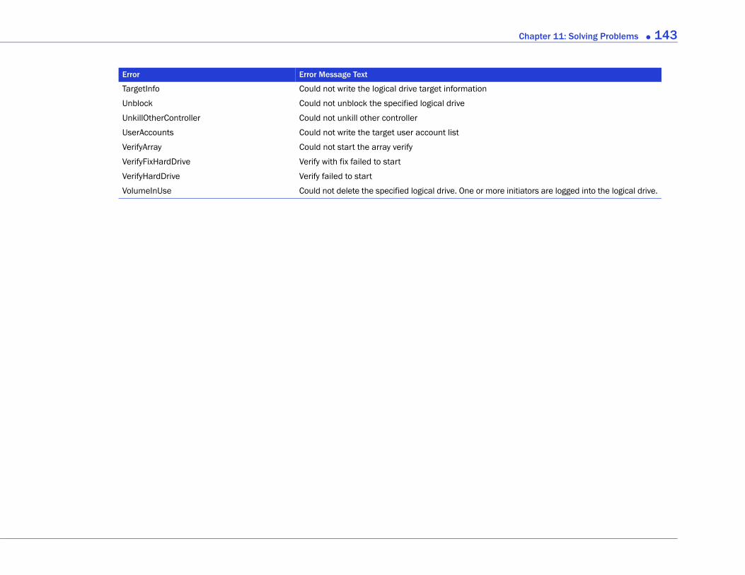
Chapter 11: Solving Problems ● 143
iators are logged into the logical drive.
TargetInfo Could not write the logical drive target information
Unblock Could not unblock the specified logical drive
UnkillOtherController Could not unkill other controller
UserAccounts Could not write the target user account list
VerifyArray Could not start the array verify
VerifyFixHardDrive Verify with fix failed to start
VerifyHardDrive Verify failed to start
VolumeInUse Could not delete the specified logical drive. One or more init
Error Error Message Text
In this part:
Completing a Silent Win
Selecting the Best RAID
Quick Answers to Comm
Buttons and Icons At-a-G
Part III:
Appendicesdows Installation ................... 145
Level ................................... 148
on Questions... ..................... 157
lance ................................... 164
A
Completing a Silent Windows InstallationIn this appendix...
Completing a Silent Installation.......................................................................................... 146
Available Properties and Values ........................................................................................... 147
Example Command Line Installations................................................................................ 147
This appendix describes for advanced users how to complete a silent Windows installation of Adaptec Storage Manager instead of following the installation instructions provided in Installing on Windows on page 19. A silent installation uses command line parameters to complete an installation without messages or user interaction.
Note: If a previous version of Adaptec Storage Manager is installed on your system, you must remove it before beginning this installation. Use the Add or Remove Programs tool in the Control Panel.

Chapter A: Completing a Silent Windows Installation ● 146
Completing a Silent InstallationYou will need the Adaptec Storage Manager Installation CD to complete this task.
To complete a silent installation:
1 Insert the CD into your CD drive.
2 Open a command prompt window and change to the CD directory.
3 Run the silent installation from the command line using one of these files, as appropriate: setup asm x64.exe or setup asm x86.exe. For example:
setup asm x86.exe /s /v" /qn <properties>"
where <properties> is one or more of the options listed in Available Properties and Values on page 147.
Separate properties with spaces; separate feature names for the ADDLOCAL property with commas (see examples on page 147).
Note: Synchronous Installation—To install Adaptec Storage Manager so that the .exe file does not close until the installation is complete, add the /w parameter to the .exe file and run the application with the start /WAIT command as shown in this example:
start /WAIT setup asm x64.exe /w /s /v" /qn <OPTIONS>"
You might want to do this for a batch file installation so that the setup will not return until the installation is finished.
After a minute or two, the silent installation should be complete and the Adaptec Storage Manager icon should be accessible. Continue with Building Your Storage Space on page 25.
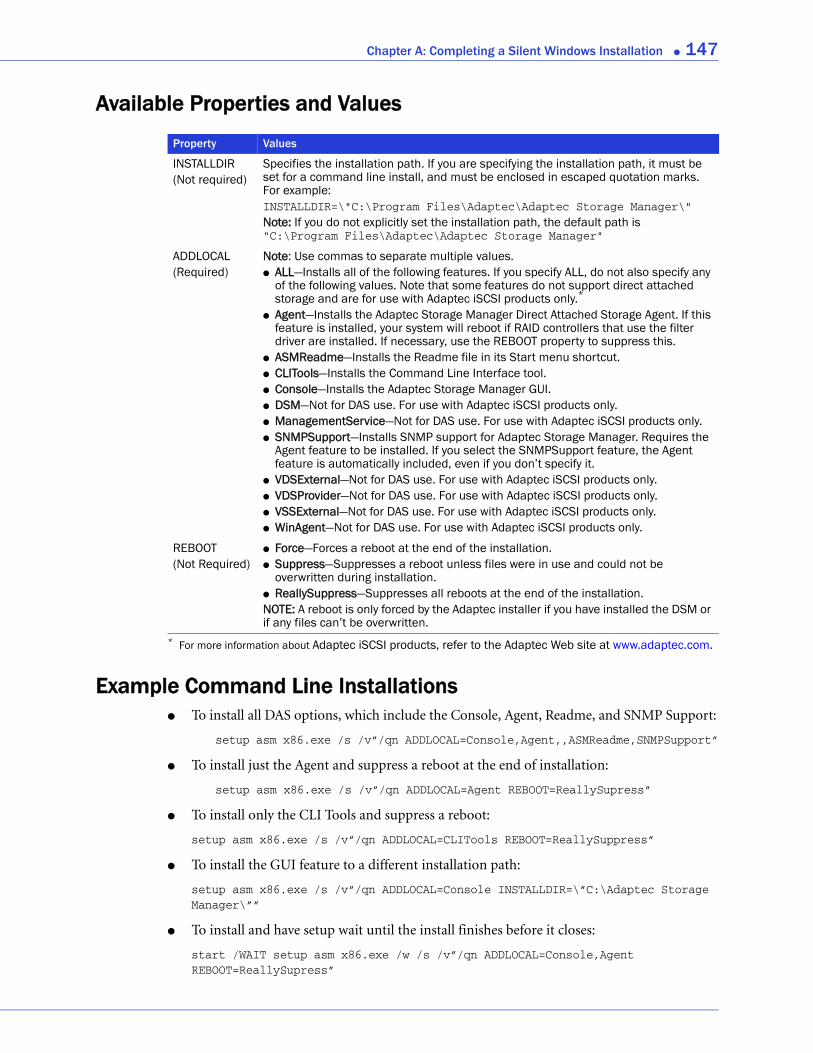
Chapter A: Completing a Silent Windows Installation ● 147
Available Properties and Values
Example Command Line Installations● To install all DAS options, which include the Console, Agent, Readme, and SNMP Support:
setup asm x86.exe /s /v”/qn ADDLOCAL=Console,Agent,,ASMReadme,SNMPSupport”
● To install just the Agent and suppress a reboot at the end of installation:
setup asm x86.exe /s /v”/qn ADDLOCAL=Agent REBOOT=ReallySupress”
● To install only the CLI Tools and suppress a reboot:
setup asm x86.exe /s /v”/qn ADDLOCAL=CLITools REBOOT=ReallySuppress”
● To install the GUI feature to a different installation path:
setup asm x86.exe /s /v”/qn ADDLOCAL=Console INSTALLDIR=\”C:\Adaptec Storage Manager\””
● To install and have setup wait until the install finishes before it closes:
start /WAIT setup asm x86.exe /w /s /v”/qn ADDLOCAL=Console,Agent REBOOT=ReallySupress”
Property Values
INSTALLDIR(Not required)
Specifies the installation path. If you are specifying the installation path, it must be set for a command line install, and must be enclosed in escaped quotation marks. For example:INSTALLDIR=\"C:\Program Files\Adaptec\Adaptec Storage Manager\"Note: If you do not explicitly set the installation path, the default path is "C:\Program Files\Adaptec\Adaptec Storage Manager"
ADDLOCAL(Required)
Note: Use commas to separate multiple values.● ALL—Installs all of the following features. If you specify ALL, do not also specify any
of the following values. Note that some features do not support direct attached storage and are for use with Adaptec iSCSI products only.*
● Agent—Installs the Adaptec Storage Manager Direct Attached Storage Agent. If this feature is installed, your system will reboot if RAID controllers that use the filter driver are installed. If necessary, use the REBOOT property to suppress this.
● ASMReadme—Installs the Readme file in its Start menu shortcut.● CLITools—Installs the Command Line Interface tool.● Console—Installs the Adaptec Storage Manager GUI.● DSM—Not for DAS use. For use with Adaptec iSCSI products only.● ManagementService—Not for DAS use. For use with Adaptec iSCSI products only.● SNMPSupport—Installs SNMP support for Adaptec Storage Manager. Requires the
Agent feature to be installed. If you select the SNMPSupport feature, the Agent feature is automatically included, even if you don’t specify it.
● VDSExternal—Not for DAS use. For use with Adaptec iSCSI products only.● VDSProvider—Not for DAS use. For use with Adaptec iSCSI products only.● VSSExternal—Not for DAS use. For use with Adaptec iSCSI products only.● WinAgent—Not for DAS use. For use with Adaptec iSCSI products only.
* For more information about Adaptec iSCSI products, refer to the Adaptec Web site at www.adaptec.com.
REBOOT(Not Required)
● Force—Forces a reboot at the end of the installation.● Suppress—Suppresses a reboot unless files were in use and could not be
overwritten during installation.● ReallySuppress—Suppresses all reboots at the end of the installation.NOTE: A reboot is only forced by the Adaptec installer if you have installed the DSM or if any files can’t be overwritten.
B
Selecting the Best RAID LevelIn this appendix...Comparing RAID Levels ...................................................................................................... 149
Understanding Drive Segments........................................................................................... 149
Non-redundant Logical Drives (RAID 0) ........................................................................... 150
RAID 1 Logical Drives.......................................................................................................... 151
RAID 1 Enhanced Logical Drives ........................................................................................ 151
RAID 10 Logical Drives........................................................................................................ 152
RAID 5 Logical Drives.......................................................................................................... 153
RAID 5EE Logical Drives ..................................................................................................... 154
RAID 50 Logical Drives........................................................................................................ 155
RAID 6 Logical Drives.......................................................................................................... 156
RAID 60 Logical Drives........................................................................................................ 156
When you create logical drives in Adaptec Storage Manager, you can assign a RAID level to protect your data.
Each RAID level offers a unique combination of performance and redundancy. RAID levels also vary by the number of disk drives they support.
This chapter provides a comparison of all the RAID levels supported by Adaptec Storage Manager, and provides a basic overview of each to help you select the best level of protection for your storage system.
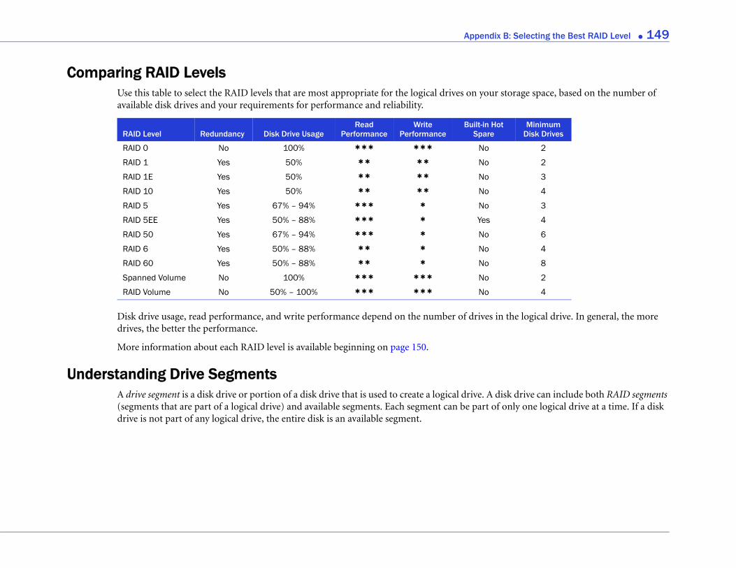
Appendix B: Selecting the Best RAID Level ● 149
rage space, based on the number of
e logical drive. In general, the more
drive can include both RAID segments ly one logical drive at a time. If a disk
MinimumDisk Drives
2
2
3
4
3
4
6
4
8
2
4
Comparing RAID LevelsUse this table to select the RAID levels that are most appropriate for the logical drives on your stoavailable disk drives and your requirements for performance and reliability.
Disk drive usage, read performance, and write performance depend on the number of drives in thdrives, the better the performance.
More information about each RAID level is available beginning on page 150.
Understanding Drive SegmentsA drive segment is a disk drive or portion of a disk drive that is used to create a logical drive. A disk(segments that are part of a logical drive) and available segments. Each segment can be part of ondrive is not part of any logical drive, the entire disk is an available segment.
RAID Level Redundancy Disk Drive UsageRead
PerformanceWrite
PerformanceBuilt-in Hot
Spare
RAID 0 No 100% ✱ ✱ ✱ ✱ ✱ ✱ No
RAID 1 Yes 50% ✱ ✱ ✱ ✱ No
RAID 1E Yes 50% ✱ ✱ ✱ ✱ No
RAID 10 Yes 50% ✱ ✱ ✱ ✱ No
RAID 5 Yes 67% – 94% ✱ ✱ ✱ ✱ No
RAID 5EE Yes 50% – 88% ✱ ✱ ✱ ✱ Yes
RAID 50 Yes 67% – 94% ✱ ✱ ✱ ✱ No
RAID 6 Yes 50% – 88% ✱ ✱ ✱ No
RAID 60 Yes 50% – 88% ✱ ✱ ✱ No
Spanned Volume No 100% ✱ ✱ ✱ ✱ ✱ ✱ No
RAID Volume No 50% – 100% ✱ ✱ ✱ ✱ ✱ ✱ No
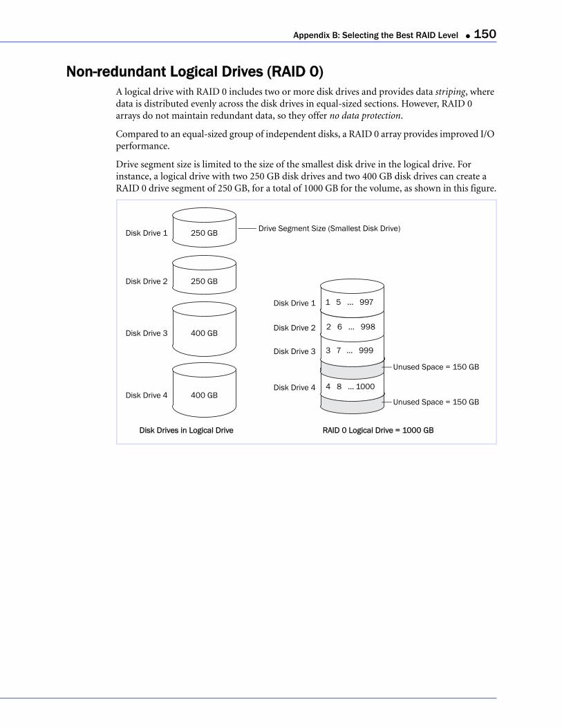
Appendix B: Selecting the Best RAID Level ● 150
Non-redundant Logical Drives (RAID 0)A logical drive with RAID 0 includes two or more disk drives and provides data striping, where data is distributed evenly across the disk drives in equal-sized sections. However, RAID 0 arrays do not maintain redundant data, so they offer no data protection.
Compared to an equal-sized group of independent disks, a RAID 0 array provides improved I/O performance.
Drive segment size is limited to the size of the smallest disk drive in the logical drive. For instance, a logical drive with two 250 GB disk drives and two 400 GB disk drives can create a RAID 0 drive segment of 250 GB, for a total of 1000 GB for the volume, as shown in this figure.
Disk Drive 1
Disk Drive 2
Disk Drive 3
Disk Drive 4
250 GB
250 GB
400 GB
400 GB
Drive Segment Size (Smallest Disk Drive)
Disk Drive 2
Disk Drive 3
Disk Drive 4
Disk Drive 1
1 5 ... 997
2 6 ... 998
3 7 ... 999
4 8 ... 1000
Unused Space = 150 GB
Disk Drives in Logical Drive RAID 0 Logical Drive = 1000 GB
Unused Space = 150 GB

Appendix B: Selecting the Best RAID Level ● 151
RAID 1 Logical DrivesA RAID 1 logical drive is built from two disk drives, where one disk drive is a mirror of the other (the same data is stored on each disk drive). Compared to independent disk drives, RAID 1 logical drives provide improved performance, with twice the read rate and an equal write rate of single disks. However, capacity is only 50 percent of independent disk drives.
If the RAID 1 logical drive is built from different-sized disk drives, drive segment size is the size of the smaller disk drive, as shown in this figure.
RAID 1 Enhanced Logical DrivesA RAID 1 Enhanced (RAID 1E) logical drive—also referred to as a striped mirror—is similar to a RAID 1 logical drive except that data is both mirrored and striped, and more disk drives can be included. A RAID 1E logical drive can be built from three or more disk drives.
In this figure, the large bold numbers represent the striped data, and the smaller, non-bold numbers represent the mirrored data stripes.
Disk Drive 2
Disk Drive 1 250 GB
400 GB
Drive Segment Size (Smallest Disk Drive)
Disk Drive 1
Disk Drive 2
Disk Drives in Logical Drive RAID 1 Logical Drive = 250 GB
1 – 250
1 – 250
Unused Space = 150 GB
Disk Drive 2
Disk Drive 1
400 GB
Disk Drives in Logical Drive RAID 1E Logical Drive = 600 GB
400 GB
400 GBDisk Drive 3
Disk Drive 2
Disk Drive 1
Disk Drive 3
1 3
2
3
4
5
6
1
2
6
4
5
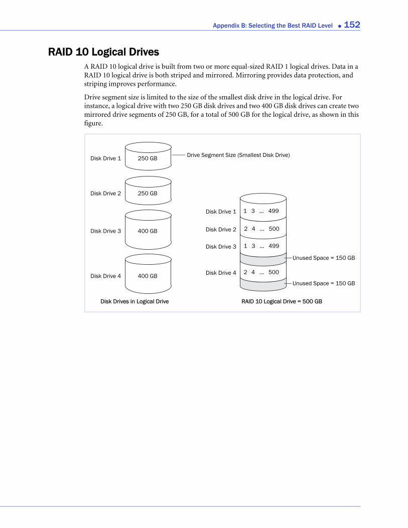
Appendix B: Selecting the Best RAID Level ● 152
RAID 10 Logical DrivesA RAID 10 logical drive is built from two or more equal-sized RAID 1 logical drives. Data in a RAID 10 logical drive is both striped and mirrored. Mirroring provides data protection, and striping improves performance.
Drive segment size is limited to the size of the smallest disk drive in the logical drive. For instance, a logical drive with two 250 GB disk drives and two 400 GB disk drives can create two mirrored drive segments of 250 GB, for a total of 500 GB for the logical drive, as shown in this figure.
Disk Drive 1
Disk Drive 2
Disk Drive 3
Disk Drive 4
250 GB
250 GB
400 GB
400 GB
Drive Segment Size (Smallest Disk Drive)
Disk Drive 2
Disk Drive 3
Disk Drive 4
Disk Drive 1
1 3 ... 499
2 4 ... 500
1 3 ... 499
2 4 ... 500
Unused Space = 150 GB
Disk Drives in Logical Drive RAID 10 Logical Drive = 500 GB
Unused Space = 150 GB

Appendix B: Selecting the Best RAID Level ● 153
RAID 5 Logical DrivesA RAID 5 logical drive is built from a minimum of three disk drives, and uses data striping and parity data to provide redundancy. Parity data provides data protection, and striping improves performance.
Parity data is an error-correcting redundancy that’s used to re-create data if a disk drive fails. In RAID 5 logical drives, parity data (represented by Ps in the next figure) is striped evenly across the disk drives with the stored data.
Drive segment size is limited to the size of the smallest disk drive in the logical drive. For instance, a logical drive with two 250 GB disk drives and two 400 GB disk drives can contain 750 GB of stored data and 250 GB of parity data, as shown in this figure.
Disk Drive 1
Disk Drive 2
Disk Drive 3
Disk Drive 4
250 GB
250 GB
400 GB
400 GB
Drive Segment Size (Smallest Disk Drive)
Disk Drive 2
Disk Drive 3
Disk Drive 4
Disk Drive 1
1 4 ... P
2 5 ... 748
3 P ... 749
P 6 ... 750
Unused Space = 150 GB
Disk Drives in Logical Drive
Unused Space = 150 GB
= 750 GB plus Parity and SpareRAID 5Logical Drive
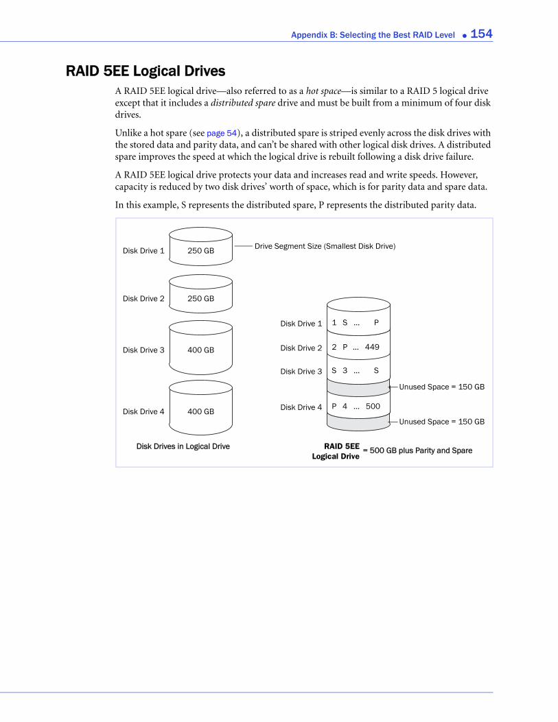
Appendix B: Selecting the Best RAID Level ● 154
RAID 5EE Logical DrivesA RAID 5EE logical drive—also referred to as a hot space—is similar to a RAID 5 logical drive except that it includes a distributed spare drive and must be built from a minimum of four disk drives.
Unlike a hot spare (see page 54), a distributed spare is striped evenly across the disk drives with the stored data and parity data, and can’t be shared with other logical disk drives. A distributed spare improves the speed at which the logical drive is rebuilt following a disk drive failure.
A RAID 5EE logical drive protects your data and increases read and write speeds. However, capacity is reduced by two disk drives’ worth of space, which is for parity data and spare data.
In this example, S represents the distributed spare, P represents the distributed parity data.
Disk Drive 1
Disk Drive 2
Disk Drive 3
Disk Drive 4
250 GB
250 GB
400 GB
400 GB
Drive Segment Size (Smallest Disk Drive)
Disk Drive 2
Disk Drive 3
Disk Drive 4
Disk Drive 1
1 S ... P
2 P ... 449
S 3 ... S
P 4 ... 500
Unused Space = 150 GB
Disk Drives in Logical Drive
Unused Space = 150 GB
= 500 GB plus Parity and SpareRAID 5EELogical Drive
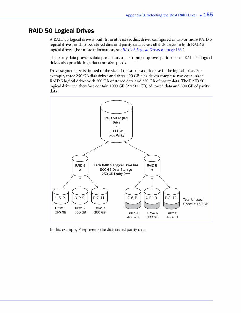
Appendix B: Selecting the Best RAID Level ● 155
RAID 50 Logical DrivesA RAID 50 logical drive is built from at least six disk drives configured as two or more RAID 5 logical drives, and stripes stored data and parity data across all disk drives in both RAID 5 logical drives. (For more information, see RAID 5 Logical Drives on page 153.)
The parity data provides data protection, and striping improves performance. RAID 50 logical drives also provide high data transfer speeds.
Drive segment size is limited to the size of the smallest disk drive in the logical drive. For example, three 250 GB disk drives and three 400 GB disk drives comprise two equal-sized RAID 5 logical drives with 500 GB of stored data and 250 GB of parity data. The RAID 50 logical drive can therefore contain 1000 GB (2 x 500 GB) of stored data and 500 GB of parity data.
In this example, P represents the distributed parity data.
RAID 5B
RAID 50 Logical Drive
=1000 GB
plus Parity
RAID 5A
Each RAID 5 Logical Drive has 500 GB Data Storage250 GB Parity Data
Drive 1250 GB
Drive 2250 GB
Drive 3250 GB Drive 4
400 GBDrive 5400 GB
Drive 6400 GB
1, 5, P 3, P, 9 P, 7, 11 2, 6, P 4, P, 10 P, 8, 12 Total Unused Space = 150 GB
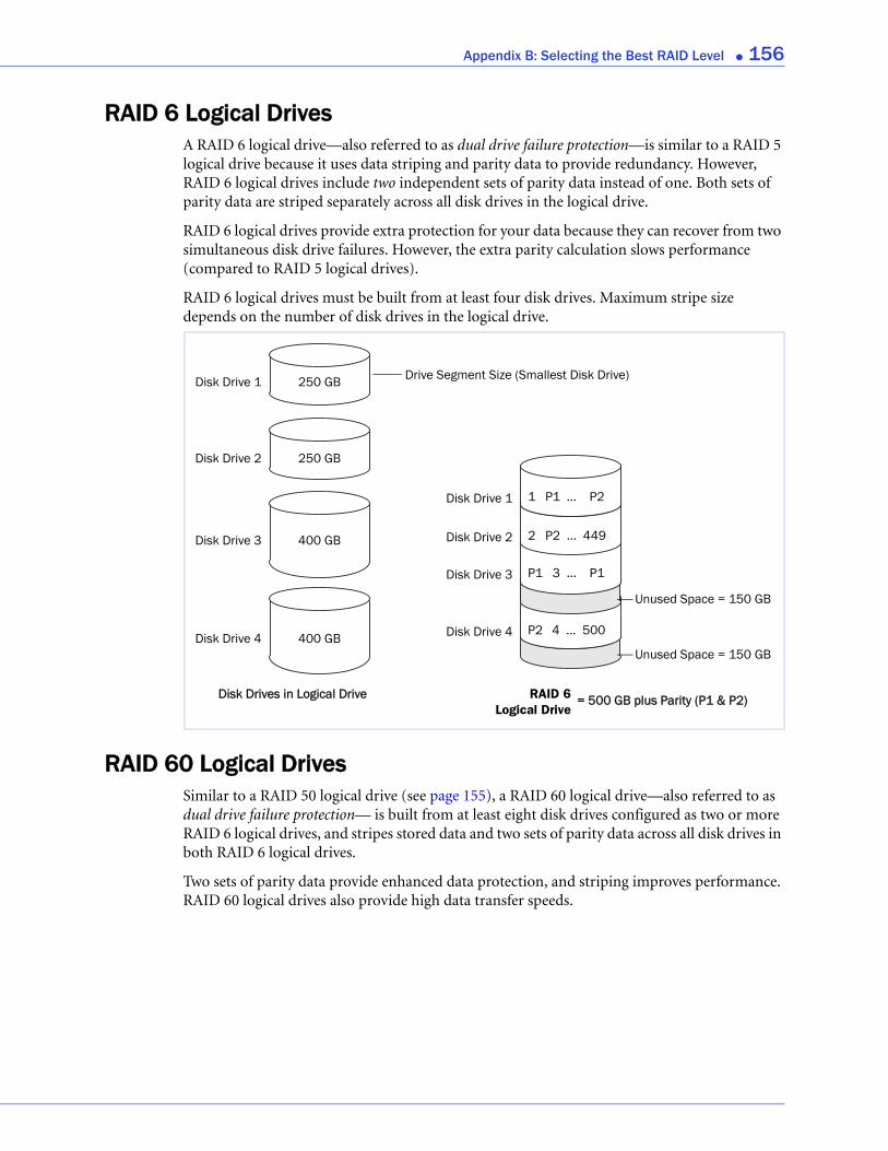
Appendix B: Selecting the Best RAID Level ● 156
RAID 6 Logical DrivesA RAID 6 logical drive—also referred to as dual drive failure protection—is similar to a RAID 5 logical drive because it uses data striping and parity data to provide redundancy. However, RAID 6 logical drives include two independent sets of parity data instead of one. Both sets of parity data are striped separately across all disk drives in the logical drive.
RAID 6 logical drives provide extra protection for your data because they can recover from two simultaneous disk drive failures. However, the extra parity calculation slows performance (compared to RAID 5 logical drives).
RAID 6 logical drives must be built from at least four disk drives. Maximum stripe size depends on the number of disk drives in the logical drive.
RAID 60 Logical DrivesSimilar to a RAID 50 logical drive (see page 155), a RAID 60 logical drive—also referred to as dual drive failure protection— is built from at least eight disk drives configured as two or more RAID 6 logical drives, and stripes stored data and two sets of parity data across all disk drives in both RAID 6 logical drives.
Two sets of parity data provide enhanced data protection, and striping improves performance. RAID 60 logical drives also provide high data transfer speeds.
Disk Drive 1
Disk Drive 2
Disk Drive 3
Disk Drive 4
250 GB
250 GB
400 GB
400 GB
Drive Segment Size (Smallest Disk Drive)
Disk Drive 2
Disk Drive 3
Disk Drive 4
Disk Drive 1
1 P1 ... P2
2 P2 ... 449
P1 3 ... P1
P2 4 ... 500
Unused Space = 150 GB
Disk Drives in Logical Drive
Unused Space = 150 GB
= 500 GB plus Parity (P1 & P2)RAID 6Logical Drive
C
Quick Answers to Common Questions...In this appendix...
How do I...?........................................................................................................................... 158
What’s the difference between...?......................................................................................... 160
What options are on the Actions menu?............................................................................. 160
What tasks can be scheduled to run at a specified time?.................................................... 163
This chapter provides quick references to frequently requested information about basic tasks, functions, and concepts in Adaptec Storage Manager.
Note: For troubleshooting tips, see Solving Problems on page 131.
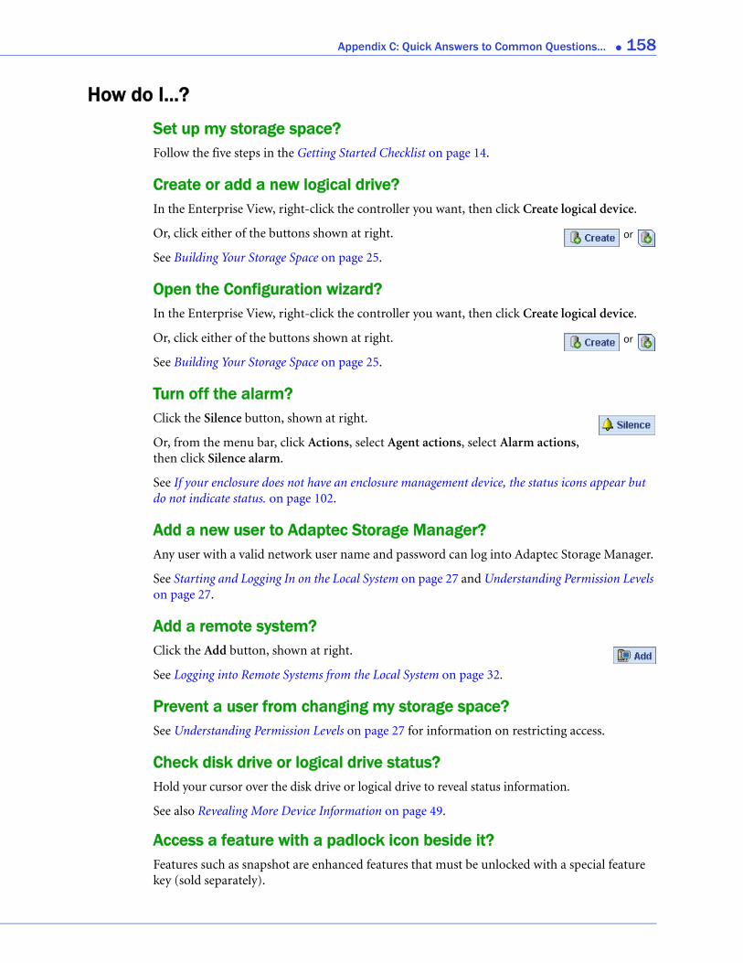
Appendix C: Quick Answers to Common Questions... ● 158
How do I...?
Set up my storage space?Follow the five steps in the Getting Started Checklist on page 14.
Create or add a new logical drive?In the Enterprise View, right-click the controller you want, then click Create logical device.
Or, click either of the buttons shown at right.
See Building Your Storage Space on page 25.
Open the Configuration wizard?In the Enterprise View, right-click the controller you want, then click Create logical device.
Or, click either of the buttons shown at right.
See Building Your Storage Space on page 25.
Turn off the alarm?Click the Silence button, shown at right.
Or, from the menu bar, click Actions, select Agent actions, select Alarm actions, then click Silence alarm.
See If your enclosure does not have an enclosure management device, the status icons appear but do not indicate status. on page 102.
Add a new user to Adaptec Storage Manager?Any user with a valid network user name and password can log into Adaptec Storage Manager.
See Starting and Logging In on the Local System on page 27 and Understanding Permission Levels on page 27.
Add a remote system?Click the Add button, shown at right.
See Logging into Remote Systems from the Local System on page 32.
Prevent a user from changing my storage space?See Understanding Permission Levels on page 27 for information on restricting access.
Check disk drive or logical drive status?Hold your cursor over the disk drive or logical drive to reveal status information.
See also Revealing More Device Information on page 49.
Access a feature with a padlock icon beside it?Features such as snapshot are enhanced features that must be unlocked with a special feature key (sold separately).
or
or
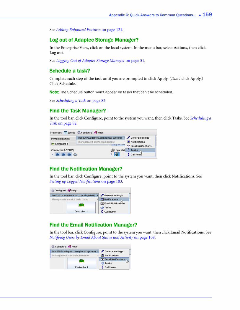
Appendix C: Quick Answers to Common Questions... ● 159
See Adding Enhanced Features on page 121.
Log out of Adaptec Storage Manager?In the Enterprise View, click on the local system. In the menu bar, select Actions, then click Log out.
See Logging Out of Adaptec Storage Manager on page 51.
Schedule a task?Complete each step of the task until you are prompted to click Apply. (Don’t click Apply.) Click Schedule.
Note: The Schedule button won’t appear on tasks that can’t be scheduled.
See Scheduling a Task on page 82.
Find the Task Manager?In the tool bar, click Configure, point to the system you want, then click Tasks. See Scheduling a Task on page 82.
Find the Notification Manager?In the tool bar, click Configure, point to the system you want, then click Notifications. See Setting up Logged Notifications on page 103.
Find the Email Notification Manager?In the tool bar, click Configure, point to the system you want, then click Email Notifications. See Notifying Users by Email About Status and Activity on page 108.
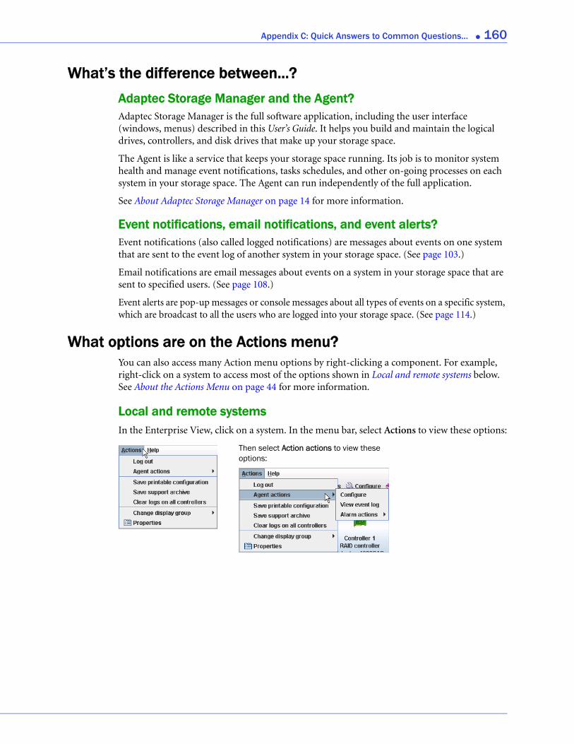
Appendix C: Quick Answers to Common Questions... ● 160
What’s the difference between...?Adaptec Storage Manager and the Agent?Adaptec Storage Manager is the full software application, including the user interface (windows, menus) described in this User’s Guide. It helps you build and maintain the logical drives, controllers, and disk drives that make up your storage space.
The Agent is like a service that keeps your storage space running. Its job is to monitor system health and manage event notifications, tasks schedules, and other on-going processes on each system in your storage space. The Agent can run independently of the full application.
See About Adaptec Storage Manager on page 14 for more information.
Event notifications, email notifications, and event alerts?Event notifications (also called logged notifications) are messages about events on one system that are sent to the event log of another system in your storage space. (See page 103.)
Email notifications are email messages about events on a system in your storage space that are sent to specified users. (See page 108.)
Event alerts are pop-up messages or console messages about all types of events on a specific system, which are broadcast to all the users who are logged into your storage space. (See page 114.)
What options are on the Actions menu?You can also access many Action menu options by right-clicking a component. For example, right-click on a system to access most of the options shown in Local and remote systems below. See About the Actions Menu on page 44 for more information.
Local and remote systemsIn the Enterprise View, click on a system. In the menu bar, select Actions to view these options:
Then select Action actions to view these options:
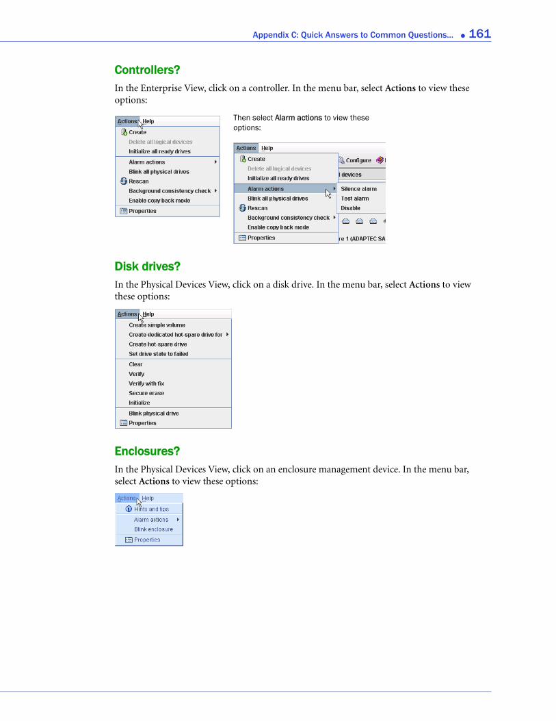
Appendix C: Quick Answers to Common Questions... ● 161
Controllers?In the Enterprise View, click on a controller. In the menu bar, select Actions to view these options:
Disk drives?In the Physical Devices View, click on a disk drive. In the menu bar, select Actions to view these options:
Enclosures?In the Physical Devices View, click on an enclosure management device. In the menu bar, select Actions to view these options:
Then select Alarm actions to view these options:
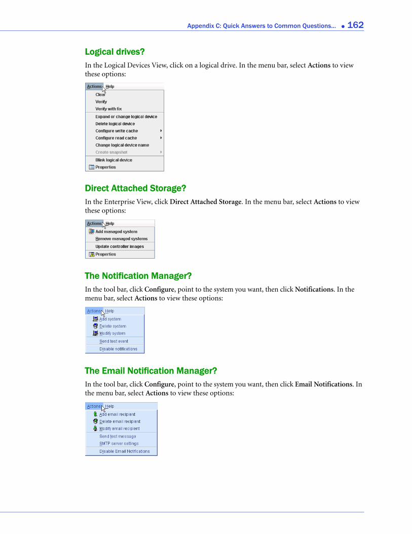
Appendix C: Quick Answers to Common Questions... ● 162
Logical drives?In the Logical Devices View, click on a logical drive. In the menu bar, select Actions to view these options:
Direct Attached Storage?In the Enterprise View, click Direct Attached Storage. In the menu bar, select Actions to view these options:
The Notification Manager?In the tool bar, click Configure, point to the system you want, then click Notifications. In the menu bar, select Actions to view these options:
The Email Notification Manager?In the tool bar, click Configure, point to the system you want, then click Email Notifications. In the menu bar, select Actions to view these options:
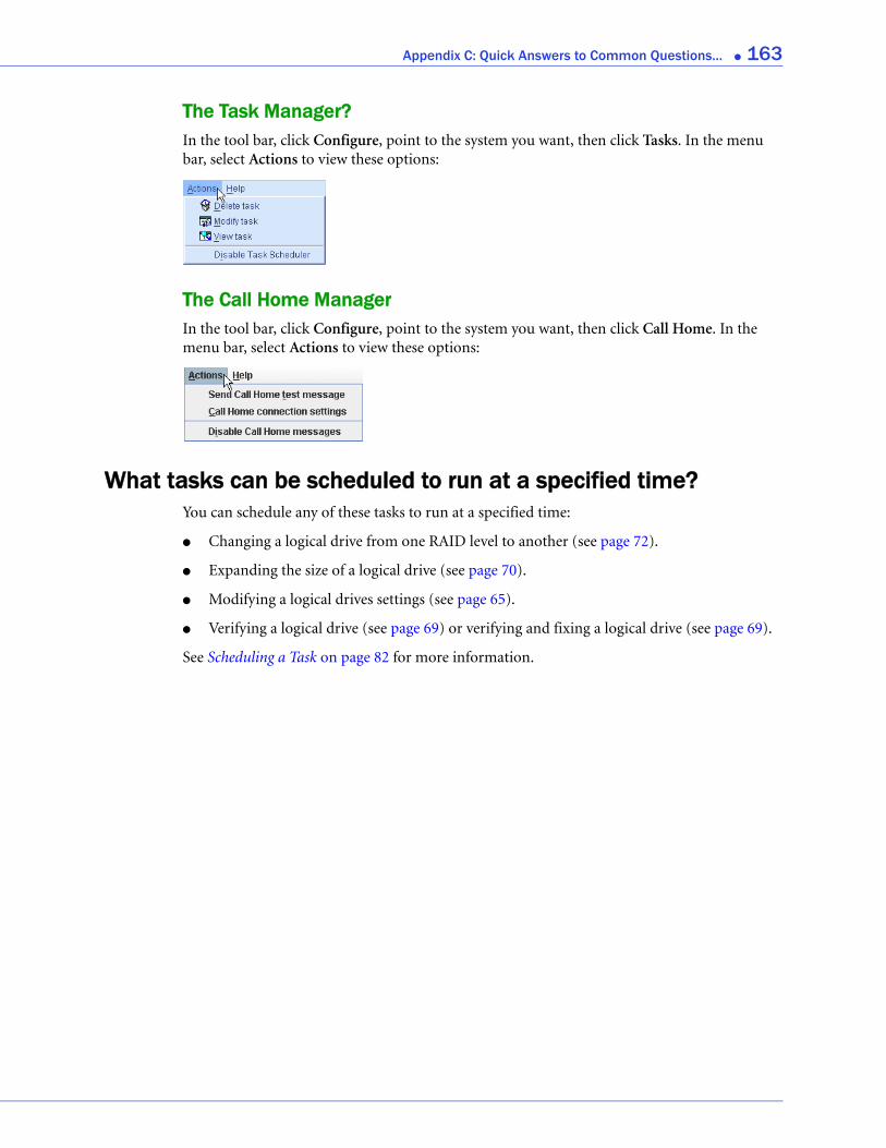
Appendix C: Quick Answers to Common Questions... ● 163
The Task Manager?In the tool bar, click Configure, point to the system you want, then click Tasks. In the menu bar, select Actions to view these options:
The Call Home ManagerIn the tool bar, click Configure, point to the system you want, then click Call Home. In the menu bar, select Actions to view these options:
What tasks can be scheduled to run at a specified time?You can schedule any of these tasks to run at a specified time:
● Changing a logical drive from one RAID level to another (see page 72).
● Expanding the size of a logical drive (see page 70).
● Modifying a logical drives settings (see page 65).
● Verifying a logical drive (see page 69) or verifying and fixing a logical drive (see page 69).
See Scheduling a Task on page 82 for more information.

D
Buttons and Icons At-a-GlanceIn this appendix...Enterprise View Icons .......................................................................................................... 165
Icons in the Physical Devices View...................................................................................... 165
Icons in the Logical Devices View ....................................................................................... 166
Buttons in the Main Window .............................................................................................. 166
Buttons in the Notification Manager .................................................................................. 167
Buttons in the Email Notification Manager........................................................................ 167
Buttons in the Task Manager ............................................................................................... 167
This chapter provides quick references to the icons and buttons that appear in Adaptec Storage Manager.
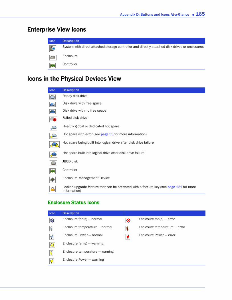
Appendix D: Buttons and Icons At-a-Glance ● 165
Enterprise View Icons
Icons in the Physical Devices View
Enclosure Status Icons
Icon Description
System with direct attached storage controller and directly attached disk drives or enclosures
Enclosure
Controller
Icon Description
Ready disk drive
Disk drive with free space
Disk drive with no free space
Failed disk drive
Healthy global or dedicated hot spare
Hot spare with error (see page 55 for more information)
Hot spare being built into logical drive after disk drive failure
Hot spare built into logical drive after disk drive failure
JBOD disk
Controller
Enclosure Management Device
Locked upgrade feature that can be activated with a feature key (see page 121 for more information)
Icon Description
Enclosure fan(s) — normal Enclosure fan(s) — error
Enclosure temperature — normal Enclosure temperature — error
Enclosure Power — normal Enclosure Power — error
Enclosure fan(s) — warning
Enclosure temperature — warning
Enclosure Power — warning
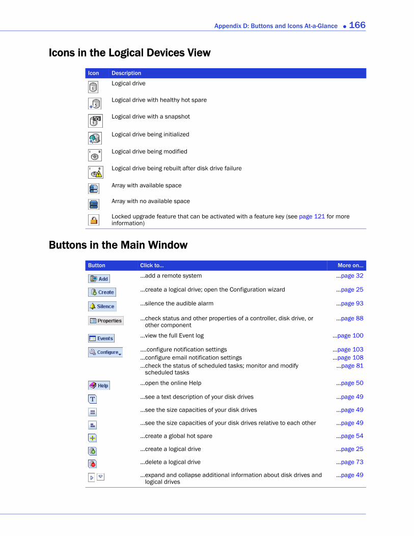
Appendix D: Buttons and Icons At-a-Glance ● 166
Icons in the Logical Devices View
Buttons in the Main Window
Icon Description
Logical drive
Logical drive with healthy hot spare
Logical drive with a snapshot
Logical drive being initialized
Logical drive being modified
Logical drive being rebuilt after disk drive failure
Array with available space
Array with no available space
Locked upgrade feature that can be activated with a feature key (see page 121 for more information)
Button Click to... More on...
...add a remote system ...page 32
...create a logical drive; open the Configuration wizard ...page 25
...silence the audible alarm ...page 93
...check status and other properties of a controller, disk drive, or other component
...page 88
...view the full Event log ...page 100
....configure notification settings
...configure email notification settings
...check the status of scheduled tasks; monitor and modify scheduled tasks
...page 103
...page 108...page 81
...open the online Help ...page 50
...see a text description of your disk drives ...page 49
...see the size capacities of your disk drives ...page 49
...see the size capacities of your disk drives relative to each other ...page 49
...create a global hot spare ...page 54
...create a logical drive ...page 25
...delete a logical drive ...page 73
...expand and collapse additional information about disk drives and logical drives
...page 49
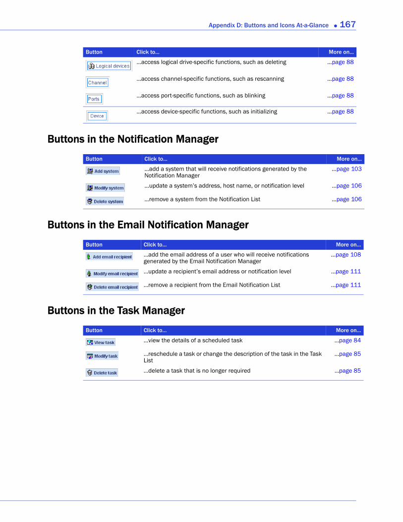
Appendix D: Buttons and Icons At-a-Glance ● 167
Buttons in the Notification Manager
Buttons in the Email Notification Manager
Buttons in the Task Manager
...access logical drive-specific functions, such as deleting ...page 88
...access channel-specific functions, such as rescanning ...page 88
...access port-specific functions, such as blinking ...page 88
...access device-specific functions, such as initializing ...page 88
Button Click to... More on...
...add a system that will receive notifications generated by the Notification Manager
...page 103
...update a system’s address, host name, or notification level ...page 106
...remove a system from the Notification List ...page 106
Button Click to... More on...
...add the email address of a user who will receive notifications generated by the Email Notification Manager
...page 108
...update a recipient’s email address or notification level ...page 111
...remove a recipient from the Email Notification List ...page 111
Button Click to... More on...
...view the details of a scheduled task ...page 84
...reschedule a task or change the description of the task in the Task List
...page 85
...delete a task that is no longer required ...page 85
Button Click to... More on...
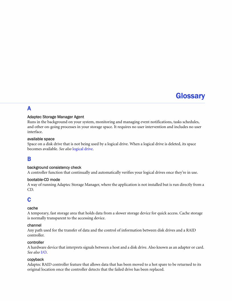
GlossaryAAdaptec Storage Manager AgentRuns in the background on your system, monitoring and managing event notifications, tasks schedules, and other on-going processes in your storage space. It requires no user intervention and includes no user interface.
available spaceSpace on a disk drive that is not being used by a logical drive. When a logical drive is deleted, its space becomes available. See also logical drive.
Bbackground consistency checkA controller function that continually and automatically verifies your logical drives once they’re in use.
bootable-CD modeA way of running Adaptec Storage Manager, where the application is not installed but is run directly from a CD.
CcacheA temporary, fast storage area that holds data from a slower storage device for quick access. Cache storage is normally transparent to the accessing device.
channelAny path used for the transfer of data and the control of information between disk drives and a RAID controller.
controllerA hardware device that interprets signals between a host and a disk drive. Also known as an adapter or card. See also I/O.
copybackAdaptec RAID controller feature that allows data that has been moved to a hot spare to be returned to its original location once the controller detects that the failed drive has been replaced.
Glossary ● 169
DDASDirect-attached Storage. Data storage that is physically connected to a server. See also LAN, SAN.
drive segmentSee segment.
dual drive failure protectionAnother name for a RAID 6 or RAID 60 logical drive.
EEmail Notification ManagerA utility within Adaptec Storage Manager that emails event messages to selected recipients. See also email notifications, Notification Manager.
email notificationsEvent messages about remote systems that are emailed to selected recipients.
eventActivity on your storage space, such as a disk drive failure or logical drive verification.
Ffault toleranceThe ability of a system to continue to perform its functions even when one or more disk drives have failed.
firmwareA combination of hardware and software; software written onto read-only memory (ROM).
formatSee initialize.
GGBGigaByte. 1,024 MB. See also MB.
HhostA system that’s connected to a TCP/IP network. See also TCP/IP.
host bus adapter (HBA)An adapter card that includes all of the I/O logic, software, and processing to manage the transfer of information between the host and the devices it’s connected to.
hot spaceA RAID 5EE logical drive. See page 154.
hot spareA spare disk drive which will automatically replace a failed disk drive in a logical drive.
hot-swapRemove and replace a failed disk drive in a logical drive without shutting down the server or disrupting activity on the logical drive.
Glossary ● 170
I Storage Manager AgentRuns in the background on your system, monitoring and managing event notifications, tasks schedules, and other on-going processes in your storage space. It requires no user intervention and includes no user interface.
initializePrepare a disk drive for reading and writing.
I/OInput/Output. Data entering into or being extracted from a system.
LLANLocal Area Network. A network of interconnected workstations sharing the resources of a single server, typically within the area of a small office building.
LEDLight-emitting Diode. An electronic device that lights up when powered.
local systemThe computer (or system) that you’re working on. In Adaptec Storage Manager, ‘local’ and ‘remote’ are relative terms. See also remote system.
logged eventsEvent messages about remote systems that appear in the event log of Adaptec Storage Manager. See also Notification Manager.
logical driveOne or more disk drives grouped together to appear as a single device to an operating system. Also known as a logical device or array.
Mmanaged systemA computer (or system) in a storage space that’s being managed by Adaptec Storage Manager.
MBMegaByte. Depending on context, 1,000,000 or 1,048,576 bytes. Also 1000 KB.
mirroringData protection that duplicates all data from one drive onto a second drive. See also RAID.
NNotification ManagerA utility within Adaptec Storage Manager that broadcasts event messages to selected managed systems.
PparityA form of data protection used by some RAID levels to re-create the data of a failed disk drive in a logical drive. See also RAID.
Glossary ● 171
partitionDivides the space of a disk drive into isolated sections.
portA connection point to a controller, disk drive, expander, enclosure, or other device.
RRAIDRedundant Array of Independent Disks. For more information on RAID and all supported RAID levels, see Selecting the Best RAID Level on page 148.
rapid fault isolationThe trail of yellow or red warning icons that leads from the high-level system view to the failed or failing component.
rebuildRe-create a logical drive after a disk drive failure.
recurring taskA scheduled task, such as logical drive verification, that occurs on a regular basis. See also Task Manager, scheduled task.
redundancyThe capability of preventing data loss if a disk drive fails. See also mirroring, parity.
remote systemIn Adaptec Storage Manager, all other systems in your storage space besides your local system are remote systems. ‘Local’ and ‘remote’ are relative terms. See also local system.
ROM Update wizardA program that updates the BIOS and firmware codes on the controller. See also firmware.
SSANStorage Area Network. A storage architecture that connects servers and disk drives across a network for enhanced reliability, scalability, and performance.
scheduled task
Activity, such as logical drive verification, that is set to be completed at a specified date and time. See also recurring task.
segmentDisk drive space that has been assigned to a logical drive. A segment can include all or just a portion of a disk drive’s space.
SMTPSimple Mail Transfer Protocol.
snapshotA frozen image of a logical drive at a particular point in time.
spareSee hot spare.
storage spaceThe controller(s) and disk drives being managed with Adaptec Storage Manager.
Glossary ● 172
stripe sizeAmount of data written to one partition before the controller moves to the next partition in a stripe set.
striped mirrorA RAID 1 Enhanced, or RAID 1E, logical drive. See page 151.
stripingA method of enhancing performance by spreading data evenly over multiple disk drives. Provides no data protection.
TTask ManagerA utility in Adaptec Storage Manager that allows you to schedule a specific activity, such as expanding a logical drive, for a time that’s convenient. See also scheduled task, recurring task.
TBTeraByte. Approximately one million-million bytes, or 1024 GB.
TCP/IPTransmission Control Protocol/Internet Protocol. A set of communication protocols used to connect hosts on the Internet.
VverifyCheck a logical drive for inconsistent or bad data. May also fix any data problems or parity errors.

IndexAActions menu 44
Add managed system 32, 124Agent actions 93
alarm 93, 95Alarm actions 91, 92, 93, 95Change logical device name 65Clear logs on all controllers 101Configure read cache 66Configure write cache 66controller-level options 161Create dedicated hot-spare drive 55Delete dedicated hot-spare drive 56Delete hot-spare drive 57Delete logical device 73, 76Direct Attached Storage branch-level options 162Disable email notifications 112Disable notifications 107Disable task scheduler 86disk drive-level options 161Email Notification Manager options 162Enable (Disable) background consistency check 70enclosure-level options 161Expand or change logical device 65, 71, 72Initialize 90Initialize all ready drives 90Log in 51Log out 51logical drive-level options 162Notification Manager options 162overview 44, 160 to 163Remove dedicated hot-spare drive 56Rescan 92Save printable configuration 92
Save support archive 137Send test event 105Send test message 110Set drive state to failed 89SMTP server settings 111system-level options 160Task Manager options 163Update controller images 96Verify 69Verify with fix 69
activity in storage spaceevent log 50
activity on storage space. See monitoringAdaptec customer support 3Adaptec Storage Manager
Actions menu 44Actions menu overview 160 to 163Agent 14beginning steps 14bootable-CD mode 23Direct Attached Storage branch 45display options 123downloading newer versions 121Email Notifications Manager 108enhanced features 121event log 100feature keys 121icons 46, 47, 48, 165 to 166installing
Linux 20OpenServer 21Solaris 21UnixWare 21VMWare 22Windows 19
Index ● 174
Windows silent installation 145introduction 14locked features 121logging into remote systems 32main window overview 44Notifications Manager 103operating system support 17standard unit of measure 123system requirements 17Task Manager 83uninstalling 51
Linux 51Windows 51
unlocking enhanced features 121updating 121
Adaptec Storage Manager vs Agent 160adapters. See controllersADDLOCAL 147Administrator permissions 27advanced settings 39, 65Agent 14
alarm settings 94event log 115introduction 14starting
Linux 31OpenServer 32Solaris 32UnixWare 32Windows 31
alarmchanging settings 94controllers
disabling 91silencing 91testing 91
disablingcontroller-level 91enclosure-level 96system-level 95
enabling (system-level) 95enclosures
disabling 96silencing 95testing 95
frequency 94systems
disabling 95enabling 95silencing 93testing 93
testingcontroller-level 91
enclosure-level 95system-level 93
archive file 137audible alarm. See alarmauto-discovery 123automatic verification 68
Bbackground consistency check 68, 70background verification 68blinking components 88boards. See controllersbootable-CD mode 23 to 24
defined 23broadcasting event alerts 114Build (initialize method) 67building storage space 25 to 41
bootable-CD mode 23custom configuration 37express configuration 34RAID Volumes 73
buttonsConfigure 104, 108Email Notification Manager 167Events 101main window 166 to 167Notification Manager 167Task Manager 167
Ccall home
see statistics loggingcards. See controllersCD mode. See bootable-CD modeClear (initialize method) 67components
blinking 88defined 11identifying 88viewing properties 88
Configuration Event Detail window 100Configure button 83, 94, 104, 126configuring 34
See also building storage spacecontroller support 17controllers
Actions menu 161blinking 88disabling alarm 91identifying 88
Index ● 175
properties 88registering 91rescanning 92saving configurations 92support by operating system 17testing alarm 91updating firmware 96
copyback 59creating with the wizard 75custom configuration 37customer support 3
Ddaemon 14DAS
defined 10dedicated hot spares 54
creating 55deleting 56removing 56
deleting logical drives 73devices 45
blinking 88Direct Attached Storage
Actions menu 162direct attached storage
Actions menu introduction 44Actions menu overview 160 to 163
Direct Attached Storage branch 45disabling alarm
enclosure-level 96system-level 95
disk drive segments 149disk drives 88
Actions menu 161available space 47blinking 88capacity 49conceptual graphic 61different sizes in same logical drive 63failed state 89failure recovery
multiple disk drives 135multiple logical drives 134RAID 0 logical drives 134with hot spare 133without hot spare 134
identifying 88initializing 90properties 88relative capacity 49
replacing in logical drives 89segments in logical drives 64text descriptions 49viewing logical drives 48viewing status 46within logical drives 38
display groups 128creating 128deleting 130moving systems 129removing systems 130renaming display groups 130system status 129
distributed spare drives 154
EEmail Notification Log
clearing 112Email Notification Manager
Actions menu 162buttons 167clearing the log 112
email notifications 108"from" address 109changing "from" address 111changing SMTP server 111disabling 112failed test emails 110modifying recipient information 111recipient addresses 108re-enabling 112removing recipients 111setup 108SMTP server settings 109test emails 110
Email Notifications log 112Email Notifications Manager 108
disabling 112Email Notifications log 112opening 108re-enabling 112test emails 110
Enclosure View 49enclosures
Actions menu 161blinking 88disabling alarm 96identifying 88monitoring 102silencing alarm 95status icons 50, 102
Index ● 176
testing alarm 95viewing disk drives 49
Enterprise View 44Direct Attached Storage branch 45icons 46, 165
Error (task status) 84event alerts 114event log 50, 100, 101
clearing 101finding source of event 103messages 103
event log (operating system) 115event notifications
Email Notifications log 112event viewer
finding source of event 103events 50Events button 101events. See monitoringExecuted (task status) 84Executed* (task status) 84expanding logical drives 70express configuration 34
RAID levels 34
Ffailed disk drives
multiple disk drives 135multiple logical drives 134RAID 0 logical drives 134without hot spare 134
fans status icon 102FAQs 157feature keys 121
unlocking 121firmware 96Force online 136formatting logical drives 36Full Size Capacity View 49
Gglobal hot spares 54
creating 39deleting 56
glossary 168Guest permissions 27
Hhard disk, hard disk drive, hard drive. See disk driveHBAs. See controllers
help 50hot spares 46, 47, 54 to 56
creating 39, 54creating dedicated 55creating pool 55dedicated, defined 54deleting 56distributed spare drives 154global, defined 54limitations 54removing 56
Iicons 46, 47, 48, 165 to 166
enclosure status icons 102Enterprise View 46, 165event status icons 101Logical Devices View 48, 166Physical Devices View 47, 165
identifying components 88initialize method 67initialize priority 67initializing disk drives 90
skipping 135INSTALLDIR 147installing Adaptec Storage Manager 18 to 21
Linux 20OpenServer 21Solaris 21UnixWare 21VMWare 22Windows 19
silent installation 145
JJBODs 75
converting to simple volumes 76creating 75deleting 76
JBODs. See also enclosuresjobs. See tasks
LLinux
controller support 17installing Adaptec Storage Manager 20SNMP support 114starting Adaptec Storage Manager 29starting the Agent 31uninstalling Adaptec Storage Manager 51

Index ● 177
local systems 26locked features 121
unlocking 121log files, clearing 112logged notifications 103
adding systems 103disabling 107failed test events 106modifying systems 106re-enabling 107removing systems 106test events 105
logging inlogging back in 51permission levels 27
logging out 51logging back in 51
Logical Devices View 44, 47icons 48, 166
logical drives 47, 61 to 74Actions menu 162advanced settings 39, 65automatic verification 68available space on disk drives 63background consistency check 68background verification 68building
advanced 37basic 34changing background task priority 36stop building 36
changing RAID levels 72custom configuration 37defined 61definition 134deleting 73different-sized disk drives 63disabling background consistency check 70disk drive segments 64, 149distributed spare drives 154enabling background consistency check 70expanding 70extending partitions 72fine-tuning 65 to 67forcing online 136formatting 36increasing capacity 70initialize method 67initialize priority 67manual verification 68maximum size 70
mirrored data 151non-redundant 150options for creating 34parity 153partitioning 36properties 88RAID 1 151RAID 10 152RAID 1E 151RAID 5 153RAID 50 155RAID 5EE 154RAID 6 156RAID 60 156RAID level 47RAID segments 149RAID Volumes 73read cache 66rebuilding 133, 136remove disk drive or segment 71renaming 65replace disk drive or segment 71replacing disk drives 89selecting disk drives 38selecting RAID levels 38size 39
limitations 40specifying size 62stripe size 66striping data 150verifying 68, 69verifying and fixing 69verifying icon 70viewing disk drives 48viewing status 47write cache setting 66
Mmain window
buttonsConfigure 110
Direct Attached Storage branch 44display options 123Enterprise View 44event details 100event log 100event log messages 103finding source of event 103Logical Devices View 44menu bar 44monitoring activity and status 100
Index ● 178
notification typesenclosure status icons 102event log 100event status icons 101
overview 44Physical Devices View 44status icons 101tool bar 44
manual verification 68mirroring 151monitoring 99 to 102, 108, 114 to 115
clearing event log 101component properties 88email notifications 108
"from" address 109changing "from" address 111changing SMTP server 111disabling 112failed test emails 110modifying recipient information 111recipient addresses 108re-enabling 112removing recipients 111setup 108SMTP server settings 109test emails 110
Email Notifications Manager 108event details 100event log 50, 100event log messages 103full event log 101logged notifications 103
adding systems 103disabling 107failed test events 106modifying systems 106re-enabling 107removing systems 106test events 105
notification typeslogged notifications 103
Notifications Manager 103options 100status icons 101tasks 84
Nnon-redundant logical drives 150Notification Manager
Actions menu 162buttons 167
notification types
email notifications 108notifications 103 to 115
event alerts 114Notifications Manager 103 to 114
clearing the log 107disabling 107modifying systems 106opening 103re-enabling 107removing systems 106test events 105
Oonline help 50opening Adaptec Storage Manager
Linux 29OpenServer 29Solaris 29UnixWare 29
OpenServercontroller support 17installing Adaptec Storage Manager 21starting Adaptec Storage Manager 29starting the Agent 32
operating system event log 115operating system support 17
Pparity 153partitioning logical drives 36partitions 72permission levels 27Physical Devices View 44, 46
icons 47, 165pool hot spares 55power management 77 to 80
disabling 79spin-up limits 79stay awake period 78timers 41, 77
power status icon 102properties 88Properties button 88
QQuick (initialize method) 67
RRAID

Index ● 179
distributed spare drives 154mirrored data 151non-redundant logical drives 150parity 153RAID 0 150RAID 1 151RAID 10 152RAID 1E 151RAID 5 153RAID 50 155RAID 5EE 154RAID 6 156
stripe size 66RAID 60 156
stripe size 66striping data 150
RAID levelschanging 72custom configuration 38express configuration 34selecting 38
RAID segments 149RAID Volumes 73RaidCfg.log file 92read cache 66REBOOT 147rebuilding (defined) 133, 134rebuilding logical drives 136recurring tasks 82registering new controllers 91Relative Size Capacity View 49remote systems 26
removing 33startup port number 33
Remote systems wizard 124renaming logical drives 65rescanning controllers 92ROM Update wizard 96running Adaptec Storage Manager
Linux 29OpenServer 29Solaris 29UnixWare 29
SScheduled (task status) 84scheduling tasks 82
rescheduling 85supported tasks 82
changing RAID level 72expanding logical drives 71
modifying logical drives 65verifying 70verifying with fix 69
See also tasksSecure erase 90segments 61, 149silencing alarm
controller-level 91enclosure-level 95system-level 93
simple volumes 76size limitations for logical drives 40size of logical drives 62Skip (initialzation method) 135SMTP server 111snapshots
creating with backup 59creating without backup 58deleting 59limitations 57snapshot backup 57snapshot nobackup 57
snapshots 59snapshots 57SNMP support
Linux 114Windows 113
software license keys 121software upgrades 121Solaris
controller support 17installing Adaptec Storage Manager 21starting Adaptec Storage Manager 29starting the Agent 32
spares. See hot sparesstandard unit of measure 123starting Adaptec Storage Manager
Linux 29OpenServer 29Solaris 29UnixWare 29
startup port number 33statistics logging 115 to 119
disabling 118enabling 30logging frequency 116, 117reporting interval 116, 117
statuscomponents 88disk drives 46, 47display group systems 129
Index ● 180
enclosures 50, 165event log 50logical drive properties 88task events 84tasks 84View buttons 49
status iconsenclosure status icons 102main window 101Task Manager 84
status. See monitoringstorage space 11
examples 15stripe size 66striping 150support archive file 137support, customer 3system groups. See display groupssystem requirements 17systems
Actions menu 160enabling alarm 95local systems 26properties 88remote systems 26testing alarm 93
TTask Event Viewer 84Task List 84Task Manager
Actions menu 163buttons 167deleting tasks 85disabling 85missed start times 85modifying tasks 85monitoring tasks 84opening 83re-enabling 86scheduling taskssupported tasks 163Task Event Viewer 84Task List 84
Task Scheduler. See Task Managertasks
deleting 85event status 84missed start times 85modifying 85monitoring 84
recurring 82scheduling 82status 84supported tasks 163
Tasks tab 83TCP/IP port number (default) 103technical support 3Technical Support Identification (TSID) number 3temperature status icon 102terminology 11test events
email notifications 110failed 110
logged notifications 105failed 106
testing alarmcontroller-level 91enclosure-level 95system-level 93
Text Description View 49tool bar buttons 166 to 167TSID Number
See Technical Support Identification Number
Uuninstalling Adaptec Storage Manager 51
Linux 51Windows 51
UnixWarecontroller support 17installing Adaptec Storage Manager 21starting Adaptec Storage Manager 29starting the Agent 32
updating Adaptec Storage Manager 121upgrade features 121
unlocking 121User permissions 27user permissions 27
Vverifying and fixing logical drives 69verifying logical drives 68, 69
automatic verification 68background verification 68icon 70manual verification 68
View buttons 49Views
enclosures 49Full Size Capacity 49

Index ● 181
Relative Size Capacity 49Text Description 49
VMWarecontroller support 17installing Adaptec Storage Manager 22
WWindows
controller support 17installing Adaptec Storage Manager 19
silent installation 145SNMP support 113starting the Agent 31uninstalling Adaptec Storage Manager 51
write cache 66write-back 66write-through 66

Adaptec, Inc.691 South Milpitas BoulevardMilpitas, CA 95035 USA
©2008 Adaptec, Inc.All rights reserved. Adaptec and the Adaptec logo are trademarks of Adaptec, Inc. which may beregistered in some jurisdictions.
Part Number: CDP-00241-01-A, Rev AJB 06/08