ADAO850Is the Hell-Coil Insert Removal Tool. 84 10 Alignment Insert Fixture for Starting Groov-Pin...
175
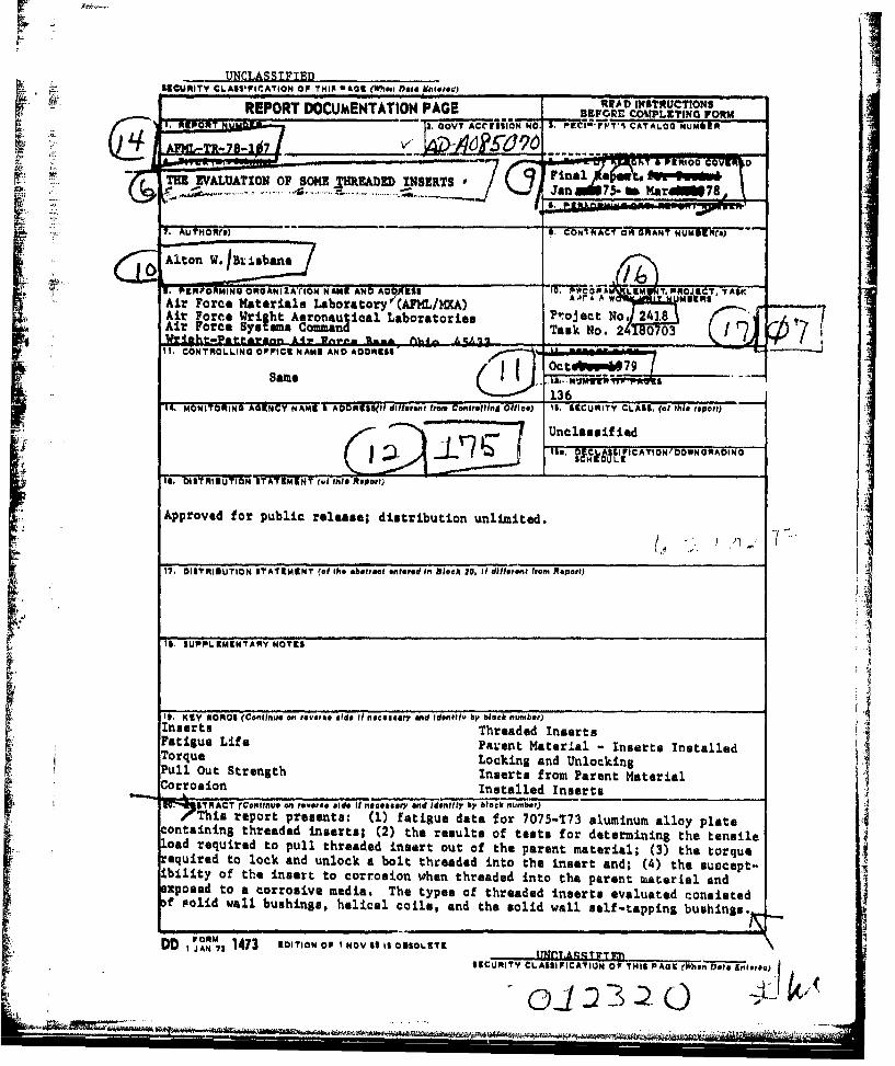
AFML-TR-78-107 ADAO850 0 THE EVALUATION OF SOME THREADED INSERTS Materials Integrity Branch Systems Support Division October 1979 TECHNICAL REPORT AFML-TR-78-107 '2fr1 C Final Report for Period January 1975 to March 1978 - A Approved for public release;, distribution unlimitedi C. • AIR FORCE MATERIALS LABORATORY AIR FORCE WRIGHT AERONAUTICAL LABORATORIES AIR FORCE SYSTEMS COMMAND WRIGHT-PATTERSON AIR FORCE BASE, OHIO 45433 ___•"" 80 5 30 059.
Transcript of ADAO850Is the Hell-Coil Insert Removal Tool. 84 10 Alignment Insert Fixture for Starting Groov-Pin...

AFML-TR-78-107
ADAO850 0
THE EVALUATION OF SOME THREADED INSERTS
Materials Integrity BranchSystems Support Division
October 1979
TECHNICAL REPORT AFML-TR-78-107 '2fr1 C
Final Report for Period January 1975 to March 1978 -
AApproved for public release;, distribution unlimitedi
C. •
AIR FORCE MATERIALS LABORATORYAIR FORCE WRIGHT AERONAUTICAL LABORATORIESAIR FORCE SYSTEMS COMMANDWRIGHT-PATTERSON AIR FORCE BASE, OHIO 45433
___•"" 80 5 30 059.

-4
When Odvernment drawings, specificatiorn, or other data are used for any pur-pose other than in oonnection with a definitely related Government procurementoperation, the United States Government thereby incurs no reaponsibility nor anyobligatlon whataoeveri and the fact that Che government may hve formulated,'furnished, or in any way supplied the said drawings, specifications, or otherdata, is net to be regarded by implioation or otherwise as in any mamer lloen-sing Uh holder or any other person or corporation, or conveying any right.s;orpermission to manufacture, use, or sell any patented invention that may In xuayway be related thereto.
This report has been reviewed by the Information Office (OX) and is z1ileaableto the National Technical nformation Service (NTIZS). At NTZS, i•t will be avail-able to the general public, including foreign nations.
This technical report has been reviewed and is approved for publication.
ALTON W. BRISBANE, Project Monitor C. L. HARMSWORTH, Technical ManagerEngineering & Design Da~t
FOR THE CONMANDER
THOMAS D. COOPER, Chief//Materials Integrity BranchSystems Support DivisionAir Force Materials Laboratory
"If your address has changed, if you wish to be removed from our mailing list,or if the addressee is no longer employed by your organixation please notifyAFML/MXA0,W-PAFB, OR 45433 to help us maintain a current mailing list".
Copies of this report should not be returned unless return is required by se-curity considerations, contractual obligations, or notice on a speolfic document.
AIR PON ICE/56710/21 May 1910 -200
UNCLASSIFIED *SESCURITY CLASSIFICATION OF TMI4IA'2 10403 ...~w I)@#& pMoloted) _________________
REPORT DOCUMENTATION PAGE BEOECMUIGFR
Ai. Force Wri!M- ht, AeronauticaCATOlNMI~f
(E4wi~ -4 50-
7S. OITRU UTIO ? TA-)M-- (ON.dC- OAi GRANTNUM
G~~~1 Alto W.IBx _ bn11. PROSRMINGTORN I ST ATEMNT No AMC .htAND ADtassd LEM TPAc J0, T, TASK@t11mRo
ArFoti e Liferil Paret Mteril -Insrts nstllTi orque Locin a nTand UNlocking 0
~"hs eor rSaen: (1) faiuedtafr105113" almiu alolt
oad requiredN toNC pullK theae DRinser otf the parent materi:Al;, (a) thireptorque
17.it DSANTof TtheN inser toe asrcr ntrosio Ihn blc0 thredifednoteprent fromia andrt
Inserdto aoroiemda ThtysofThreaded Inserts eautdtosseT orqud albsighlclcis n h okidg wall self-taping buhns
Pul out~ Strngt EInTerts fromVParet MateriaCorrosionteu

AFML-TR-78-107
FOREWORD
This evaluation was conducted by personnel of the Materials Integrity
Branch, Air Force Materials Laboratory. This work was conducted in
response to TN-ASD-AFML-1305-74-31., "Threaded Insert Evaluation." The
work was conducted under Project No. 2418, Task No. 24180703. Alton W.
Brisbane of AFML/MXA was the project engineer.
The evaluation was conducted during the period of January 1975 to
December 1977. The author wishes to express his appreciation to Messers
Robert Urzi, AFML/MXA, Richard Stewart, ASD/ENFEN, Richard Martin of
UDRI, and Larry Salinas, ASD/SDZ8D for their assistance during the con-
duct of this program.
Data contained in this report shall not be used in any way for
promotion or advertising purposes.
, 11,, - *dJ. *1:,7<
1 i Lit .- ,
Sttt... ......... . . • ,'

AFML-TR-78-107
TABLE OF CONTENTS
SECTION PAGE
I INTRODUCTION I
II OBJECTIVE 3
III THREADED INSERT SELECTION 4
1. Solid Wall Inserts 4
2. Helical Coil Inserts 6
3. Self-Tapping Inserts 7
IV INSERT MANUFACTURER AND INSERT DESIGNATIONS 8
V TENSILE TESTS OF PARENT MATERIAL 9
VI EXPERIMENTAL 10
1. Specimen Preparation for Fatigue Tests 10
2. Installation of Inserts 10
3. Tools Required for Insert Installation 11
VII FATIGUE TESTS 12
1. Results 13
VIII TENSILE STRENGTH PULL OUT SPECIMEN PREPARATION 14
1. Experimental 14
2. Results of Tensile Pull Out Tests 15
IX LOCKING AND BREAKAWAY TORQUE TEST 16
1. Specimen Preparation 16
2. Results 16

AFML-TR-78-107
TABLE OF CONTENTS (CONTINUED)
SECTION PAGE
X CORROSION TESTS 18
1. Experimental 19
2. Results of Corrosion Tests 19
X1 CONCLUSIONS 20
REFERENCES 21
APPENDIX
I STATISTICAL ANALYSIS OF THREADED INSERTS 123"TEST DATA
1. INTRODUCTION 124
2. SUMMARY OF RESULTS 125
3. STATISTICAL ANALYSIS 127
3.1 Fatigue Tests 1273.1.1 Life Tests 1273.1.2 Breakaway Torques After Cyclic Loading 131
3.2 Axial Strength Tests 132
3.3 Locking and Breakaway Torque Tests 133
vi
•'•. • .. ---------........ - -.
AFML-TR-78-107
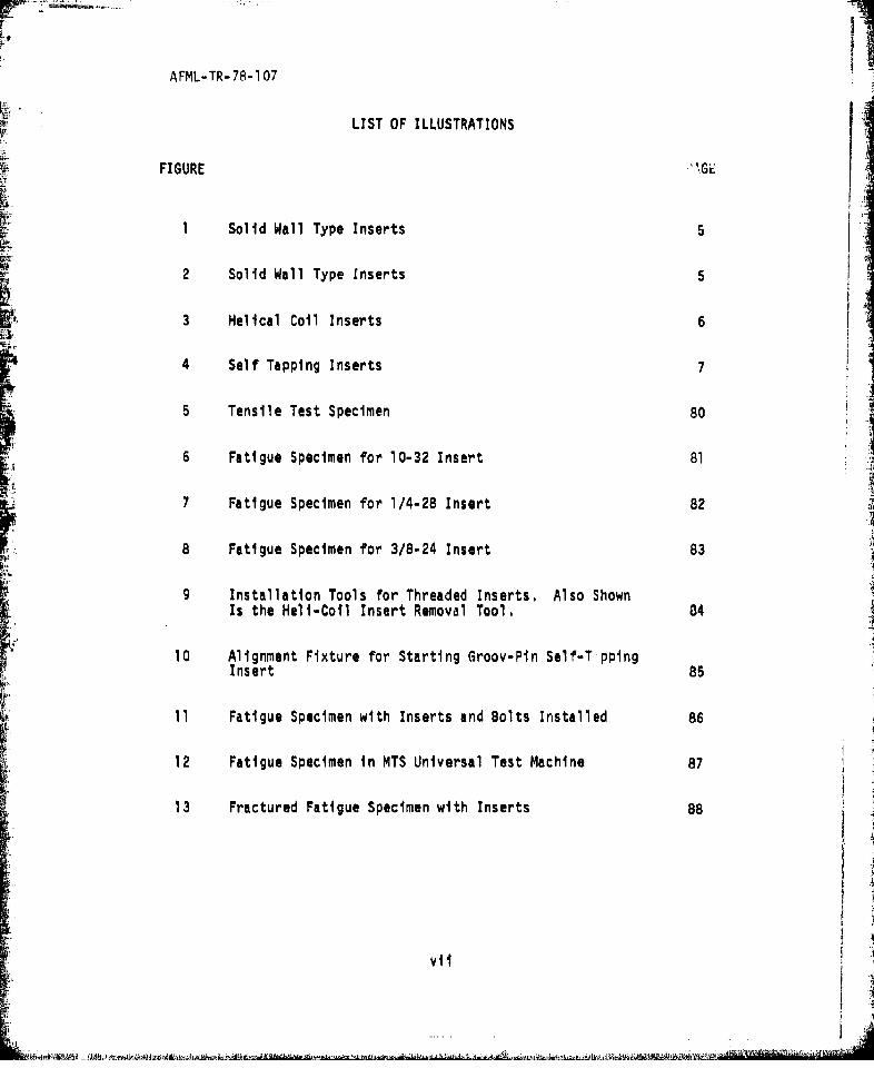
LIST OF ILLUSTRATIONS
FIGURE
1 Solid Wall Type Inserts
2 Solid Wall Type Inserts
3 Helical Coil Inserts 6
4 Self Tapping Inserts
5 Tensile Test Specimen 80 A
6 Fatigue Specimen for 10-32 Insert 81
7 Fatigue Specimen for 1/4-28 Insert 82
8 Fatigue Specimen for 3/8-24 Insert 83
9 Installation Tools for Threaded Inserts. Also ShownIs the Hell-Coil Insert Removal Tool. 84
10 Alignment Fixture for Starting Groov-Pin Self-T,1ppingInsert 85
11 Fatigue Specimen with Inserts and Bolts Installed 86
12 Fatigue Specimen in MTS Universal Test Machine 87
13 Fractured Fatigue Specimen with Inserts 88
v..

IAFML-TR-78-107
LIST OF ILLUSTRATIONS (CONTINUED)
FIGURE PAGE
14 Bar Graph Showing the Fatigue Life of the 7075-T73
Alloy with 1/4-28 Inserts Only 89
15 Bar Graph Showing Fatigue Life of the 7075-T73 Alloy 90with 1/4-28 Inserts and Bolts
16 Bar Graph Showing the Fatigue Life of the 7075-T73 91Alloy with 10-32 Size Inserts & Bolts Installed
17 Bar Graph Showing the Fatigue Life of 7075-T73 Alloy 92with 3/8-24 Size Inserts and Bolts
18 Insert Pull Out Specimens and Corrosion Specimen 93
19 Test Set-up for the Tensile Pull Out of Threaded 94Inserts
20 Locking and Unlocking Torque Specimen Lay Out 95
21 Typical Torque Wrench and Specimen for Locking and 96Breakaway Torque Tes~ts
22 Close-up of Fatigue Failure of Specimens with Groov-Pinand Long-Lok 10-32 Size Inserts. Inserts Installed by 97Manufacture. Torqued Bolts in Insert During Tests.
23 Close-up of Fatigue Failures of Specimens with Rosan,Tridair, and Heli-Coil 10-32 Size Insert. InsertsInstalled by Manufacture, Torqued Bolts in InsertsDuring Tests.
24 Close-up of Fatigue Failures of Specimens with Long-LokRosan, and Kaynar 10-32 Size Inserts. Inserts Installedby AFML. Torqued Bolts in Inserts During Tests. 98
viii

I
AFML-TR-78-107
LIST OF ILLUSTRATIONS (CONTINUED)
FIGURE PAGE
25 %,lose-up of Fatigue Failures of Specimens with Tridairand Groov-Pin 10-3? Size Inserts. Inserts Installedby AFML. Torqued Bolts in Inserts During Tests. 98
26 Close-up of Fatigue Failure of Specimen with Hell-CoilInsert. Insert Installed by AFML. Torqued Bolts inInsert During Test. 99
27 Close-up of Fatigue Failure of Specimens with Rosan andGroov-Pin 1/4-28 Size Insert. Inserts Installed byManufacture. Torqued Bolts in Inserts During Tests. 99
28 Close-up of Fatigue Failures of Specimens with Tridairand Long-Lok 1/4-28 Size Inserts. Inserts Installedby Manufacture. Torqued Bolts in Inserts During Tests. 100
29 Close-up of Fatigue Failure of Specimens with Hell-
Coil 1/4-28 Size Inserts. Torqued Bolts in InsertsDuring Tests. 100
30 Close-up of Fatigue Failure of Specimens with Hell-Coil 1/4-28 Size Insert. Inserts Installed by AFML,Torqued Bolt in Inserts During Test, 101
31 Close-up of Fatigue Failure of Specimens with Rosen,Groov-Pin, and Long-Lok 1/4-28 Size Insert. InsertsInstalled by AFML. No Bolt in Inserts. 101
32 Close-up of Fatigue Failure of Specimens with Hell-Coil,Tridair, and Kaynar 1/4-28 Size Inserts. Inserts In-stalled by AFML. No Bolt in Inserts. 102
33 Close-up of Fatigue Failures of Specimens with NoInserts. 1/4 Inch Diameter Holes. 102
ix
A~AAMA

AFML-TR-78l107
LIST OF ILLUSTRATIONS (CONTINUED)
FIGURE PAGE
34 Close-up of Fatigue Failure of Specimen with Rosanand Kaynar 1/4-28 Size Inserts. Inserts Installedby AFML. Torqued Bolts in Inserts During Tests. 103
35 Close-up of Fatigue Failures of Specimens with Groov-Pin and Tridair 1/4-28 Size Inserts. Inserts Installedby AFML. Torqued Bolts in Inserts During Tests. 103
36 Close-up of Fatigue Failure of Specimens with Long-
Lok Insert. Inserts Installed by AFML. TorquedBolts in Inserts During Test, 104
re1
37 Close-up of Fatigue Failures of Specimens with Long-Lok and Hell-Coil 3/8-24 Size Inserts. InsertsInstalled by AFML. Torqued Bolts in Inserts DuringTests, 104
38 Close-up of Fatigue Fracture of Specimens with Tridair3/8-24 Size Insert. Insert Installed by AFML. Torqued 0Bolt in Inserts During Test, 105
39 Close-up of Fatigue Failures of Specimens with Groov-Pin and Rosan 3/8-24 Sl1c Inserts. Inserts Installedby AFML. Torqued Bolts in Inserts During Tests. 105
a,)
40 Close-up of Fatigue Failure of Specimens with Tridairand Groov-Pin 1/4-28 Size Insert. Inserts Installedby Manufacture. 106
41 Close-up of Fatigue Failures of Specimen with Rosanand Tridair 3/8-24 Size Inserts. Inserts Installedby Manufacture. Torqued Bolts in Inserts DuringTests. 106
42 Close-up of Fatigue Failure of Specimens with Groov-Pin Size Inserts. Inserts Installed by Manufacture,Torqued Bolts in Inserts During Test. 107
x
AFML-TR-78-107
LIST OF ILLUSTRATIONS (CONTINUED)
FIGURE PAGE
43 Close-up of Fatigue Failure of Specimens with Heli-Coil 3/8-24 Size Inserts. Inserts Installed byManufacture. Torqued Bolts in Inserts During Test. 107
44 Close-up of Fatigue Failure of Specimens with Hell-Coil and Rosan 1/4-28 Size Inserts. Inserts Installedby Manufacture. No Bolt in Inserts. 108
45 Close-up of Fatigue Failure of Specimens with Long-Lok1/4-28 Size Inserts. Inserts Installed by Manufacture.No Bolts in Inserts. 108
46 Corrosion Specimen with Washer and Bolt 109
47 Corrosion Specimen 110
48 Corrosion Specimen 111
49 Corrosion Specimen 112
so Corrosion Specimen 113
S51 Corrosion Specimen 114
52 Corrosion Specimen 115
53 Corrosion Specimen 11653 Corrosion Specimen 16.
54 Corrosion of Parent Material Surface 117
55 Corrosion Specimen with Bolt Removed 118
xi

AFML-TR-78-107
LIST OF ILLUSTRATIONS (CONTINUED)
FIGURE PAGE
56 Corrosion Specimen after Cleaning 11957 Corrosion Specimen after Cleaning 119
58 Corrosion Specimen after Cleaning 120
59 Corrosion Specimen after Cleaning 120
60 Corrosion Specimen after Cleaning 121
61 Corrosion Specimen after Cleaning 121
62 Corrosion Specimen after Cleaning 122
63 Average L2fe for Manufacturers - 1/4-28 Tests 141
64 Average Life for Manufacturers - 10-32 Tests 142
65 Average Life for Manufacturers - 3/8-24 Tests 143
66 Average Breakaway Torque Differences - 10-32 FatigueTests 144
67 Average Breakaway Torque Differences - 1/4-28 Fatigue 145Tests
68 Average Breakaway Torque Differences - 3/8-24 Fatigue 146Tests
69 Average Axial Strengths - 10-32 Size Specimens 147
70 Average Axial Strengths - 1/4-28 Size Specimens 148
xii

AFML-TR-78-107
LIST OF ILLUSTRATIONS (CONTINUED)
FIGURE PAGE
71 Average Axial 5trengths - 3/8-24 Size Specimens 149
72 Average Bolt Locking/Unlocking Torques for RepeatedApplications - Kaynar Inserts 150
73 Average Bolt Locking/Unlocking Torques for Repeated 15OApplications - Rosan Inserts 151
74 Average Bolt Locking/Unlocking Torques for RepeatedApplications - Hell-Coil Inserts 152
75 Average Bolt Locking/Unlocking Torques for Repeated 1Applications, - Tridair Inserts 153
76 Average Bolt Locking/Unlocking Torques for Repeated 1Appli.ations - Long-Lok Inserts 154
77 Average Bolt Locking/Unlocking Torques for RepeatedApplications - Torkon Inserts 155
78 Average Bolt Locking/Unlocking Torques for Repeated 5Applications - Groov-Pin Inserts 16
Tii.
xlii

AFML-TR-78-1 07
LIST OF TABLES
TABLE PAGE
Insert Sizes and Identification for EvaluationProgram 8
2 Results of Tensile Strength Tests of 7075-T173Aluminum Alloy - Plate 9
3 Breakaway Torque Before and After Fatigue Tests -Bolt Initially Torqued to 35 In-Lbs 22
4 Breakaway Torque Before and After Fatigue Tests -
Bolt Initially Torqued to 70 In-Lbs 23
5 Breakaway Torque Before and After Fatigue Tests -Bolts Initially Torqued to 245 In-Lbs 24
6 Breakaway Torque Before and After Fatigue Tests -Bolt Initially Torqued to 35 In-Lbs 25
7 Breakaway Torque Before and After Fatigue Tests -
Bolt Initially Torqued to 70 In-Lbs 26
P--akaway Torque Before and After Fatigue Tests -
Bolts Initially Torqued to 245 In-Lbs
9 Breakaway Torque Before and After Fatigue Tests -Bolt Init'ally Torqued to 35 In-Lbs 28
10 Breakaway Torque Before and After Fatigue Tests -Bolt Initially Torqued to 70 In-Lbs 29
11 Breakaway Torque Before and After Fatigue Tests -
Bolts Initially Torqued to 245 In-Lbs 30
xiv

AFML-TR-78-107
LIST OF TABLES (CONTINUED)
TABLE PAGE
12 Breakaway Torque Before and After Fatigue Tests -
Bolt Initially Torqued to 35 In-Lbs 31
13 Breakaway Torque Before and After Fatigue Tests -
Bolt Initially Torqued to 70 In-Lbs 32
14 Breakaway Torque Before and After Fatigue Tests-Bolts Initially Torqued to 245 In-Lbs 33
15 Breakaway Torque Before and After Fatigue Tests -Bolt Initially Torqued to 35 In-Lbs 34
16 Breakaway Torque Before and After Fatigue TestsBolt Initially Torqued to 70 In-Lbs 35
17 Breakaway Torque Before and After Fatigue Tests -Bolts Initially Torqued to 245 In-Lbs 36
18 Breakaway Torque Before and After Fatigue Tests -Bolt Initially Torqued to 35 In-Lbs 37
19 Breakaway Torque Before and After Fatigue Tests -Bolt Initially Torqued to 70 In-Lbs 38
20 Breakaway Torque Before and After Fatigue Tests -
Bolts Initially Torqued to 24,5 In-Lbs 39
21 Breakaway Torque Before and After Fatigue Tests -
Bolt Initially Torqued to 35 In-Lbs 40
22 Breakaway Torque Before and After Fatigue Tests -Bolt Initially Torqued to 70 In-Lbs 41!41
xv
-d. -I' - -
AFML-TR-78-107
LIST OF TABLES (CONTINUED)
TABLE PAGE
23 Breakaway Torque Before and After Fatigue TeutsBolts Initially Torqued to 245 In-Lbs 42
24 The Average Breakaway Bolt Torque Before and AfterFatigue Tests 43
25 Results of Fatigue Tests of 7075-T73 Aluminum Alloywith 1/4-28 Threaded Holes and Smooth Holes 44
26 Results of Fatigue Tests of 7075-T73 Aluminum Alloy
with 1/4-28 Threaded Inserts Only 45
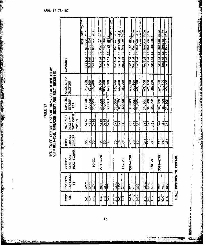
27 Results of Fatigue Tests of 7075-T73 Aluminum Alloywith Hell-Coil Threaded Insert and Bolt Installed 46
28 Results of Fatigue Tests of 7075T73 Aluminum Alloy 47with Tridair Threaded Insert and Bolt Installed I
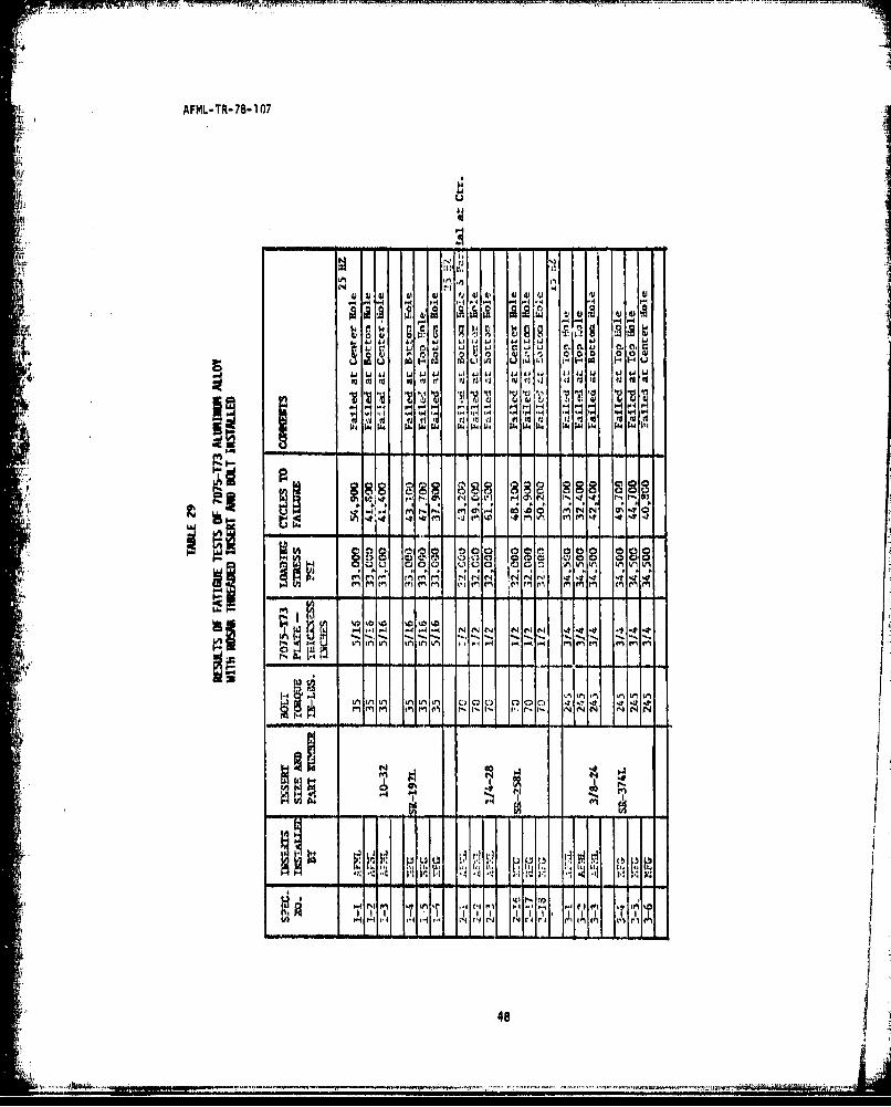
29 Results of Fatigue Tests of 7075-T73 Aluminum Alloywith Rosan Threaded Insert and Bolt Installed 48
30 Results of Fatigue Tests of 7075-T73 Aluminum Alloywith Kaynar Threaded Insert and Bolt Installed 49
31 Results of Fatigue Tests of 7075-T73 Aluminum Alloywith Long-Lok Threaded Insert and Bolt Installed 50
32 Results of Fatigue Tests of 7075-T73 Aluminum Alloy
with Torkon Threaded Insert and Bolt Installed 51
33 Results of Fatigue Tests of 7075-T73 Aluminum Alloywith Groov-Pin Threaded Insert and Bolt Installed 52
34 Percentage Increase or Decrease of the Fatigue Lifeof 7075-T73 Alloy with Threaded Holes When 1/4-28 53Inserts Are Added or When Inserts and Bolts Are Added
xvi

AFML-TR-78-107
LIST OF TABLES (CONTINUED)
TABLE PAGE
35 Room Temperature Axial Strength Tests 54
36 Pull Out Tensile Strength Averages of Inserts Installedin 7075-T73 Aluminum 56
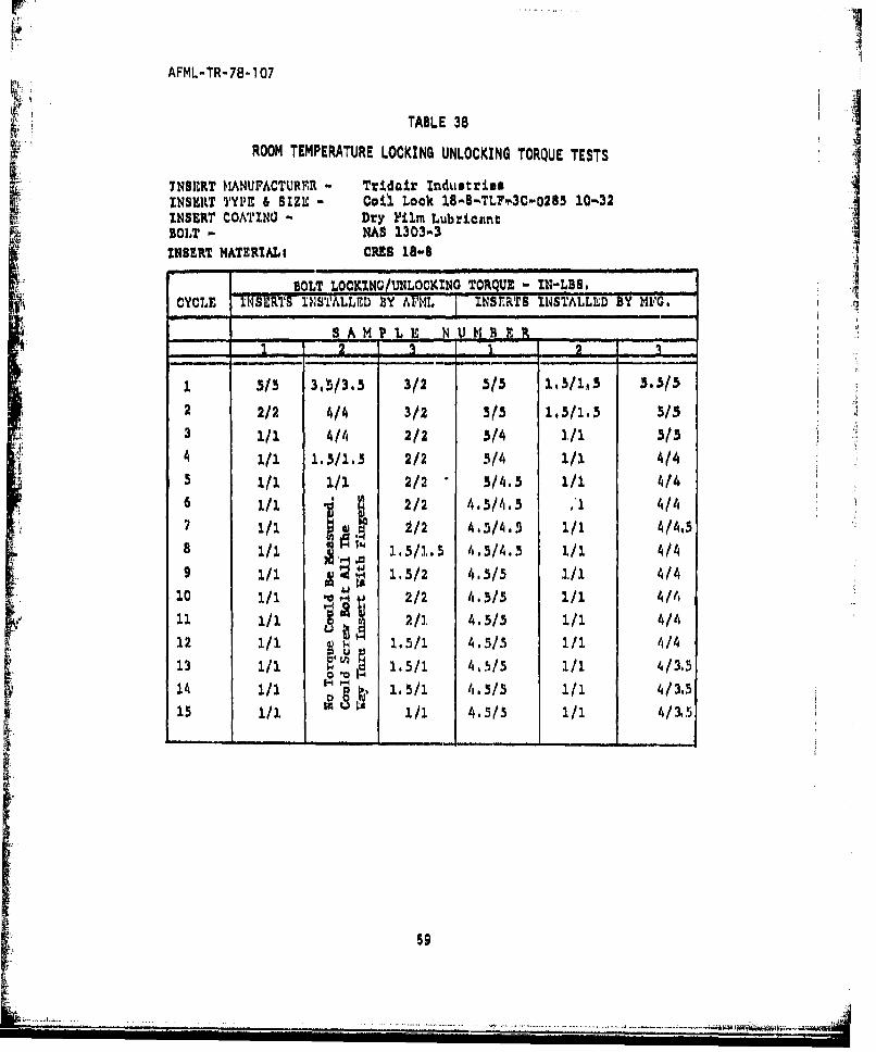
37 Room Temperature Locking Unlocking Torque Tests 58
38 Room Temperature Locking Unlocking Torque Tests
39 Room Temperature Locking Unlocking Torque Tests 60
40 Room Temperature Locking Unlocking Torque Tests 61
4 R-41 Room Temperature Locking Unlocking Torque Tests 62
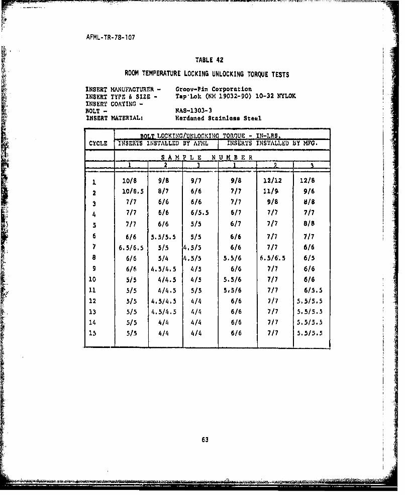
42 Room Temperature Locking Unlocking Torque Tests 634
43 Room Temperature Locking Unlocking Torque Tests 64 -A
45 Room Temperature Locking Unlocking Torque Tests 656
45 Room Temperature Locking Unlocking Torque Tests 66
-g46 Room Temperature Locking Unlocking Torque Tests 67
47 Room Temperature Locking Unlocking Torque Tests 68
48 Room Temperature Locking Unlocking Torque Tests 69
49 Room Temperature Locking Unlocking Torque Tests 70
L xvi1
- ------- --- .-.-... ,------ . -----

AFML-TR-78-1 07
LIST OF TABLES (CONTINUED)
TABLE PAGE
50 Room Temperature Locking Unlocking Torque Tests 71
51 Room Temperature Locking Unlocking Torque Tests 72
52 Room Temperature Locking Unlocking Torque Tests 73
53 Room Temperature Locking Unlocking Torque Tests 74
54 Room Temperature Locking Unlocking Torque Tests 75
55 Room Temperature Locking Unlocking Torque Tests 76
56 Room Temperature Locking Unlocking Torque Tests 77
57 Room Temperature Locking Unlocking Torque Tests 78
58 Averages of the First Cycle, Seventh Cycle and FifteenthCycle of the Locking and Breakaway Torque Test for Each 79SAze Insert
59 Fatigue Lives from 1/4-28 Tests (K Cycles to Failure) 134
60 Analysis of Variance Table for Fatigue Lives from1/4-28 Tests 135
61 Analysis of Variance Table for Fatigue Lives from10-32 Tests 136
62 Analysis of Variance Table for Fatigue Lives from
3/8-24 Tests
63 Analysis of Variance Table for Breakaway TorqueDifferences - 10-32 Fatigue Tests 136
64 Analysis of Variance Table for Breakaway TorqueDifferences - 1/4-28 Fatigue Tests 137
xviii
L 4

AFML-TR-78-107
LIST OF TABLES (CONTINUED)
TABLES PAGE
65 Analysis of Variance Table for Breakaway Torque"Differences - 3/8-24 Fatigue Tests 137
66 Analysis of Variance Table for Axial Strength - 10-32Size Specimens 138
67 Analysis of Variance Table for Axial Strength - 1/4-28Size Specimens 138
68 Analysis of Variance Table for Axial Strength - 3/8-24Size Specimens 139
69 Percent Reduction of Average Locking and BreakawayTorques 140
ii

AFML-TR-78-107
SECTION I
INTRODUCTION
There are currently many types of threaded metal inserts which are
commercially available, These inserts are used to allow the fasteningof one material with screws or bolts to another material without having
the screw or bolt threaded directly into the second material. The lastoverall testing of threaded inserts was accomplished about 1964. Many
of the products tested then are no longer available, Therefore, It was
desirable to test several of the currently available inserts to characterizemechanical and corrosion characteristics,
Threaded inserts are used In many of the softer materials such as
aluminum, magnesium, and nonmetallics. The hard material of the insert canwithstand the frequent removal of the screws or bolts more so than the softmaterials.
The number and type of Insert systems was necessarily limited due tothe cost and manpower involved in an evaluation program, The particular
systems selected were chosen to be representative of systems found in
aircraft structure, In general the program was limited to not more than
two products of a given type (e.g., self-tapping) and only one type of
threaded insert from each manufacturer.
The evaluation of threaded inserts reported herein was requested by
the Deputy for Engineering, Flight Equipment Division, Mechanical Branchof the Air Force Aeronautical Systems Division, (ASD/ENFEM). The insertswere tested for static pullout strength, the effect of insert on fatiguelife of parent material with and without fasteners Installed, locking
Sand unlocking torque of the fastener, and corrosion susceptibility. The
approach was to have the participating insert manufacturers install insertsin half of the specimens to be tested. The other half were installed
"adulcigtru ftefsee, n orso ucpiiiy h

AFML-TR-78-1 07
at the AFML. Testing of all the inserts was accomplished by the AirForce Materials Laboratory, Systems Support Divisions Materials IntegrityBranch (AFML/MXA) at Wrigh~t-Patterson AFB.
2
..- ...... ...- - -. ...

AFML-TR-78-107
SECTION II
OBJECTIVE
The main objective of this program was to provide engineering test
data on threaded inserts, for general use in airframe structures, The
information derived from this study in conjunction with data from other
sources. can be used in evaluating insert systems for Air Force use.
9 41
3

42r~- --~-~ ---------
AFML-TR-78-107
SECTION III
THREADFD INSERT SELECTION
The tests were designed to determine several characteristics of thethreaded insert system.
The following insert types were selected as being representative of
those found in typical aircraft structures: (1) solid wall bushing typeinserts, (2) wire coil type inserts, and (3) a self-tapping type insert.
All of the inserts were the self-locking type, internal and external.
1. SOLID WALL INSERTS
There are several varieties of the solid wall bushing type insert.For this evaluation program the non-self-tapping solid wall inserts usedare shown in Figure 1. Both of the inserts shown have a thin wall made
of type 303 stainless steel. These inserts have an Integral plastic
(nylon) self-locking element which extends through the wall of the in-
sorts. On one type the plastic is longitudinal in the threads and in
the other the plastic is radial in the threads. A dry film lubricantis used on the insert to prevent galling and seizing between the inter-nal threads of the insert and the bolts and it also prevents seizing oninstallation. The inserts shown in Figure 1 can be installed into the
parent material either end first.
The other variety of solid wall inserts are shown in Figure 2.
Both of these inserts also have a thin wall. One is made of CRES PH 17-4
stainless steel heat treated to 180-200 KSI. The other insert is madeof a heat treated alloy steel and is cadmium plated. Both inserts are
coated with a dry film lubricant. The Internal thread locking mechanismfor both inserts is mechanical caused by deformed thread shape. The two
inserts also have external locking in which the area at the top of the
Insert is serrated. The serrated area is swaged outward into the
parent material during installation locking the Insert to the parent
material,
4

AFML-TR-78-1 07
Figure 1. Solid Wall Type Inserts
LIZ,
IKR
Figure 2. Sol id Wall1 Type Insert

AFML-TR-78-1 07
2. HELICAL COIL INSERTS
The two helical coil type inserts operate on the same principle.
These inserts are shown in Figure 3. In the free state the diameter of
the insert is larger than the tapped hole in which it will be installed.
In assembly the insert is reduced in diameter, threaded into place, andretained by the insert attempting to expand to its original diameter.
Internal locking between the insert and the bolt is achieved by a series
of cords on one or more of the insert convolutions. The threading of
the holes for the coil wire inserts requires a tap designed for wire
inserts.
Figure 3. Helical Coil Insert
6

AFML-TR-78-107
3. SELF-TAPPING INSERT
The self-tapping insert is a bushing with Internal and external
threads, The insert is designed to cut its own threads as it is screwed
into a drilled or cored hole. The cutting edges are formed by several
transverse holes drilled through the wall of the pilot portion of the
insert as shown in Figure 4. These transverse holes also allow for the
discharge of chips during the self-tapping operation. The insert material
is hardened stainless steel. The internal and external thread lockinn
mtchanisrr is a nylon pellet nresspd into a hole drilled throunh the
wall of the insert,
K *1
rigure 4, Self-Tapping Insert
7a - -
AFIML-TR-78-107
SECTION IV
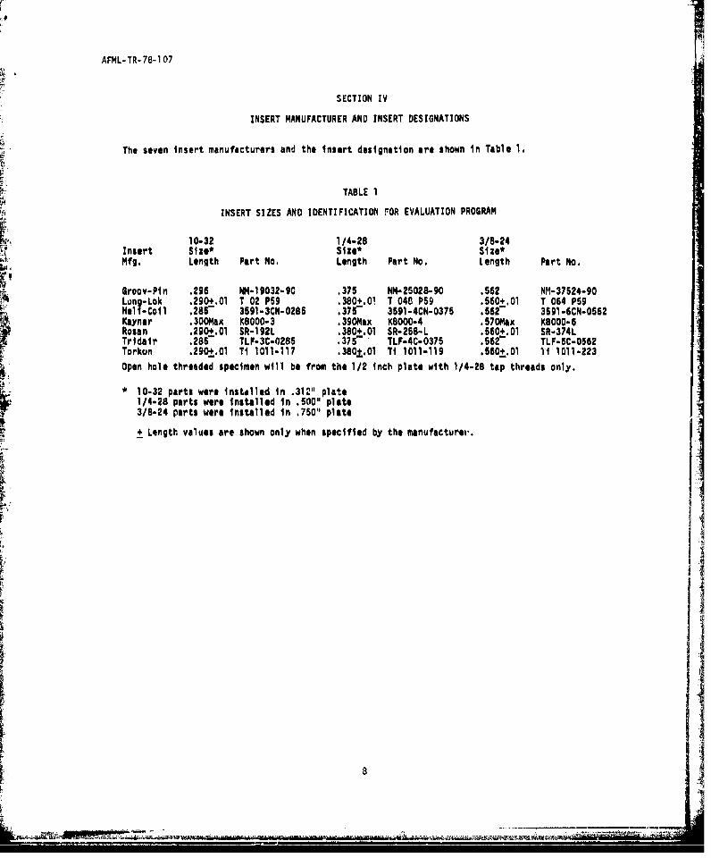
INSERT MANUFACTURER AND INSERT DESIGNATIONS
The seven insert manufacturers and the insert designation are shown in Table 1.
TABLE 1
INSERT SIZES AND IDENTIFICATION rOR EVALUATION PROGRAM
10-32 1/4-28 3/8-24Insert Size* Size* Size*Mfg. Length Part No. Length Pert No. Length Part No.
Groov-Pin .2g6 NM-19032-90 .375 NM-25028-90 .562 NM-37524-90Lung-Lok .290+.O1 T 02 P59 .380+.O0 T 040 P59 .560+.0l T 064 P59Helt-Coil .2857 3591-3CN-0285 .375 3591-4CN-0375 .562 3591-6CN-0562Kaynar .30OMax K8OOO-3 .39ONax KBOOO-4 .5700Mx K8000-6Rosan .290+.0l SR-192L .380+.Ol SR-258-L .560+.Ol SR-374LTridair .2867 TLF-3C-0286 .375- TLF-4C-0376 .5627 TLF-5C-0562Torkon .290,.01 Ti 1011-117 .380o.01 TI 1011-119 .660.O1 Ti 1011-223
Open hole threaded specimen will be from the 1/2 Inch plate with 1/4-28 tap threads only.
10-32 parts were installed in .312" plate1/4-28 parts were installed in .500" plate3/8-24 parts were Installed in .750" plate
+ Length values are shown only when specified by the manufacturev.
A8-
It

AFML-TR-78-107
SECTION V
TENSILE TESTS OF PARENT MATERIAL
Tensile specimens from each thickness of material were machined In
accordance with the drawing shown in Figure 5.
Six tensile specimens were prepared from each thickness of the 7075-T73
plate material. The plate thicknesses were 5/16-Inch, 1/2-inch and 3/4-Inch.The tensile test specimens were tested in a 10,000-pound capacity Instrontest machine. The specimens were tested at ambient temperature and at astrain rate of 0.005 inch/inch per minute. The mechanical properties of
the 7075-T73 aluminum alloy are given in Table 2.
TABLE 2
RESULTS OF TENSILE STRENGTH TESTS OF 7075-T73ALUMINUM ALLOY - PLATE
SPEC, MATERIALS YIELD ULTIIMATE ELONGATION REDUCTION INNO. THIMCKESS STRESS STRMSS V - I OL. AREA - X'KSI KS7
1 5/16" 53.5 65.7 13.0 29.02 " 54.0 65.1 11.0 31.03 " 54.5 65.4 12.0 33.04 0 53.5 65.6 12.0 31.05 " 53.6 65.7 11.0 31.0
6 " 53.9 65.2 13.0 32.0AVERAdE 5. " 3.8 65.45 12.0 31.2
1 1/2" 50.9 63.7 111.0 38.02 " 50.9 64.1 15.0 39.03 51.7 63.7 15.0 38.04 50.9 64.1 14.0 38.05 " 50.5 63.7 16.0 38.06 " 50.5 3.5 16.0 38.0
AVERAC, . 50.9- 6IT.8 15.0 38.2
1 3/4" 56.6 69.7 14.0 33.02 " 56.4 69.7 13.0 31.03 l 55.1 68.2 13.0 31.04 56.6 69.3 13.0 33.05 " 56.0 69.2 12.0 33.06 " 57.4 70,3 3.3.0 33, r)
AVERAGE 56.3 69.4 13.0 32.3
9

AFML-TR-78-107
SECTION VI
EXPERIMENTAL
1. SPECIMEN PREPARATION FOR FATIGUE TESTS
The fatigue specimens were made as shown in Figures 6, 7, and 8.
The specimens were machined by the Millet Industries Corporation, Dayton,
Ohio, The aluminum material was received In the 7075-T6 condition andwas over-aged to the 7075-T73 condition. Fatigue specimens for the 10-32
Lsize inserts were machined from 5/16-inch thick aluminum, the fatigue
specimens for the 1/4-28 size inserts were machined from 1/2-inch thickaluminum plate and the fatigue specimens for the 3/8-24 size inserts were
machined from 3/4-inch thick aluminum plate.
The Insert holes were prepared In accordance with the manufacturers,
recommended instructions. All holes were checked after they were tappedfor go/no-go. The tapped holes for the wire inserts required a tapdesigned for helical coil inserts.
2. INSTALLATION OF INSERTS
The installation of the various inserts required installation toolsdesigned for that type of insert. These tools were furnished by the
participating insert manufacturers. The program was set up so that themanufacturers would install inserts in one half of the specimens to beevaluated. These specimens were shipped to the manufacturers for installa-tion of the inserts. AFML installed the inserts in the remaining half
of the specimens at WPAFB.
The Long-Lok, Torkon, Tridair, Hell-Coil, and Groov-Pin insertsrequired only one operation for installation after hole preparation.The Kaynar and the Rosen inserts required two operations for installation
after hole preparation. These two inserts had to be first screwed into
10
- .-
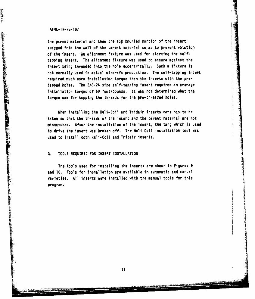
AFML-TR-78-107
the parent material and then the top knurled portion of the Insert
swagged into the wall of the parent material so a3 to prevent rotation
of the insert. An alignment fixture was used for starting the self-
tapping insert. The alignment fixture was used to ensure against the
insert being threaded into the hole eccentrically, Such a fixture is
not normally used in actual aircraft production. The self-tapping insertrequired much more installation torque than the inserts with the pre-
tapped holes. The 3/8-24 size self-tapping insert required an average
installation torque of 69 foot/pounds. It was not determined what the
torque was for tapping the threads for the pre-threaded holes,
When installing the Hell-Coil and Tridair inserts care has to be
taken so that the threads of the insert and the parent material are not
mismatched. After the installation of the insert, the tang which is used
to drive the insert was broken off. The Hell-Coil installation tool was
used to install both Hell-Coil and Tridair inserts.
3. TOOLS REQUIRED FOR INSERT INSTALLATION
The tools used for installing the inserts are shown in Figures 9
and 10. Tools for installation are available in automatic and manual; varieties. All inserts were installed with the manual tools for thisS~ program.
i4
Ii•'11
....................................

AFML-TR-78-107
SECTION VII
FATIGUE TESTS
The fatigue testing phase of the evaluation was to dqtermine theeffect that the insert had on the fatigue life of the parent material andthe effect of fatigue loading on the breakaway torque of the insert system.
In order to obtain control fatigue data, specimens from 1/2-inch
also with only the insert installed in the hole.
A fatigue specimen with the bolts installed in the inserts is shownin Figure 11. A washer with a recessed hole was installed under thebolt head so that when the bolt was torqued down there would be a loadtransfer through the bolt into the insert and Into the parent material.The 10-32 size bolt was torqued to 35 inch-pounds, the 1/4-28 size boltwas torqued to 70 inch-pounds, and the 3/8-24 size bolt was torqued to
245 inch-pounds. The initial torque for each size bolt was recorded.The breakaway torque before starting the test was also recorded. The
bolt was then retorqued to the original value and the specimens werecycled to failure or 106 cycles. After failure of the parent materialthe breakaway torque of the two remaining bolts was recorded. Thetorque data are shown in Tables 3 through 23.
All fatigue specimens were cycled at 50 percent of the parent material(7075-T73) ultimate tensile stress.
The test machine used to conduct the fatigue tests was a MTS 50 KIPcapacity universal fatigue test machine. The test set up Is shown inFigure 12. All tests were conducted at room temperature in ambient air.
12
.... ..... I

AFIML-TR-78-107
All of the fatigue tests were conducted at a stress ratio of Min. Stress/
Max. Stress of 0.1 (tension-tension). The test frequency was 25 Hz for
the 5/16-Inch and 1/2-inch thick material and 15 Hz for the 3/4-inch
thick material.
1. RESULTS
Fatigue tests on the 7075-T73 alloy were conducted on specimens
with: (1) threaded holes, (2) with inserts In the threaded holes, andI (3) bolts installed in the Inserts. A statistical analysis indicates
that the installation of the inserts alone increased the fatigue life
over the threaded holes for all cases except for specimens with Torkon
and Groov-Pin inserts. This analysis is based on data taken from Tables
25 and 26 and the results are shown In Table 34. Additional tests with
bolts installed in the inserts indicated a further increase In fatigue
life for all specimens including the specimens with Torkon and Groov-Pin
inserts; although the overall increase for specimens with Torkon and
Groov-Pin inserts when compared with the threaded hole only, was less.
More important; however, is the total fatigue life of the overall system
with the fastener installed.
The results of all of the fatigue test data are tabulated In Tables
25 through 33 and summarized in the bar graphs shown in Figures 14 through
17. The pattern of the fatigue failures did not seem to change between
the 5/16-inch (10-32 inserts) thick plate, the 1/2-Inch (1/4-28 inserts)
thick plate, and the 3/4-inch (3/8-24 inserts) thick plate. A failed ifatigue specimen is shown In Figure 13. Photo macrographs of represents-
tive failed specimens are shown in Figures 22 through 45. The averages
of the breakaway torque before and after fatigue testing are shown in
Table 24. In general the breakaway torque either increased or remainedessentially the same, Above tests were for 1/4-28 Inserts only.
Results of other size inserts with bolts are shown in bar graphs in
Figure 16 and Figure 17.
13
-----------------------------------------

AFML-TR-78-107
SECTION VIII
TENSILE STRENGTH PULL OUT SPECIMEN PREPARATION
The specimens as shnwn in Figure 18 were machined by Millet Indus-
tries Corporation, Dayton, Ohio. The specimens were machined from 1-1/2
inch diameter 7075-T73 aluminum bar. The holes for all three sizes ofinserts (10-32, 1/4-28, 3/8-24) were drilled and tapped In accordance
with the Insert manufacturer's recommended instructions, All holes werechecked for go/no-go. The installation of all inserts were the same as
detailed in the section on insert installation.
1. EXPERIMENTAL
The tensile strength pull out tests were conducted on a 50,000-pound
capacity FGT testing machine. All tensile tests for insert pull out were
conducted at room temperature at a loading rate of approximately 100 KSI
per minute. The test set up is shown in Figure 19. The bolts used were
as follows. Bolts for the 10-32 size inserts were part number BMS5132-3-30A,
bolts for the 1/4-28 size Inserts were part number BM9022-4-36, and the
bolts used for the 3/8-24 size Inserts were part number BM3306-6-35.
The bolt material was H-11 steel.
The length of all inserts was approximately 1-1/2 times the insert
diameter. The inserts were installed in the specimens to a depth equal-
Ing the full length of the insert. The bolt used for pulling the insert
out of the parent material was screwed into the Insert until two threads
of the bolt extended beyond the length of the insert. A new bolt was
used for each test.
Tensile strength pull out tests were performed on six specimens ofeach size submitted by all seven manufacturers. All tensile tests were
conducted to failure so as to establish the ultimate pull out load of
the installed insert or the failure load of the bolt.
14

AFML-TR-78-1 07
2. RESULTS OF TENSILE PULL OUT TESTS
The results of the axial strength tests is given in Table 35.
The type of axial strength test failure for all of the insertstested was either the bolt failed or the threads of the parent materialpulled out, There was never a failure of the insert material or thebolt threads stripping off. In Table 35, It is indicated by an asterisk
) denoting the tests in which the bolt failed prior to insert pull out.Shown In Table 36 is an average of the axial tensile strength of theinserts according to type.
..... I ...
.U
V&I-I
$•ig.F
15p
r
-~ 5 ~r~ ij"'•--
AFML-TR-78-107
SECTION IX
LOCKING AND BREAKAWAY TORQUE TESTS
1.* SPECIMEN PREPARATION
7 The inserts of all three sizes were Installed in a 1" X 3" X 12"L 7075-T73 aluminum plate as shown In Figures 20 and 21. A separate plate
was used for each manufacturer's insert, The Insert installation proce-WEI, dures were the same as previously stated. The tests were performed in
accordance with the general provisions of Specification MIL-N-25027C.In all cases cadmium plated steel bolts were used. Each test consistedof 15 locking and breakaway cycles. The locking and breakaway torque
were recorded for each cycle. A new bolt was used for each l1 cyclep test. The 1" X 3" X 12" plate was clamped to the surface of a workbench. All tests were accomplished manually. The torque wrenches used
were as follows: for the 10-32 Inserts a Sturtevant Memory Model MC25-1,
0-25 Inch-pounds; for the 1/4-28 inserts, a Sturtevant Memory Model MC5O-1,0-50 Inch-pounds wrench; and for the 3/8-24 size inserts, a Sturtevant
Memory Model MC300-1, 0-300 inch-pounds wrench was used. To start thetest, the test bolt was finger screwed into the insert to the lockingmechanism. Then using the torque wrench the bolt was screwed severalrevolutions Into the insert making sure the locking mechanism was fully
engaged. All inserts had both external and internal locking mechanisms.There were three types of locking mechanisms; nonmetallic, metallic and
what Hell-Coil and Tridair refer to as resilient locking thread.
2, RESULTS
The results of the locking and breakeway torque tests for the 10-32size inserts are given in Tables 37 through 43. There is no data for
the 10-32 size Inserts installed by Kaynar because the specimens were
not returned to AFML. The results of the locking and breakaway torque
16
v ,, . . ..-.. • • .• • • • ,•• .. . . . . . ... • ••= " • - - -. ...
AFML-TR-78-1 07
tests for the 1/4-28 inserts are given in Tables 44 through 50. The
results of the locking and breakaway torque tests for the 3/8-24 size
inserts are given in Tables 51 through 57. The average of first cycle
locking and breakaway torque, the average of the seventh cycle locking
and breakaway torque, and the average of the 15th cycle locking andbreakaway torque for each size Insert and for each manufacturer is given
in Table 58.
During the torque tests no rotation of Inserts were observed,
There was only one noticeable abnormality. During the testing of one
of Tridair's 10-32 Inserts after five cycles the inmert lost its lock-
ability. The torque was not measurable, and the bolt could be screwed
past the locking mechanism with fingers.
.•.
N I• "I
ii
L174

AFML-TR-78-107
SECTION X
CORROSION TESTS
The corrosion test specimens were machined as shown in Figure 18.The specimens were made from 1-1/2 inch diameter 7075-T73 aluminum.Specimens were made only for the 1/4-28 size inserts. The Installation
of all inserts was the same as detailed in the section on insert Installa-tion.
Prior to the Installation of inserts into the corrosion specimen,
and after all machining was completed, the specimen blocks were treatedwith MIL-C-5541 chemical surface treatment,
1. EXPERIMENTAL
The corrosion test specimens consisted of 42, 1-1/2 Inch dia., 1-inchlong aluminum block. A 1/4-28 hole was made in each blank. Then six1/4-28 size inserts from each manufacturer were installed, Each specimen
was then assembled with NAS 1351 series bolt and a corrosion resistantwasher as shown in Figure 46. Each 1/4-28 bolt was torqued to 70 inch-
pounds, The corrosion tests were conducted in accordance with ASTM-G44-75,
The corrosion miedia was 3-1/2 percent NaCl solution. The specimens were
immersed in the solution for ten minutes and out of solution for 50 minutes.This procedure was repeated for 30 days.
The corrosion media was changed weekly. The cpeclmens were examined Iperiodically during the 30-day corrosion test.
After the completion of the 30-day corrosion test, the specimens weresectioned in half with the bolt still intact. Due to the hardened surface
of the Groov-Pin inserts, it was not possible to cut through that insertwith the saw being used.
18
A.$1

AFML-TR-78-107
2. RESULTS OF CORROSION TESTS
The corrosion test specimens were sectioned in half after the com-pletion of the alternate immersion corrosion tests. Figures 47 through
53 show the specimens immediately after sectioning with corrosion products
in place, and Figures 56 throughi 62, show the same specimens after clean-
ing. All of the specimens showed evidence of pitting corrosion in thelower portion of the drilled hole below the insert. Surprisingly, and
considering the lack of any sealant or other protective medium, no evi-dence of corrosion was observed at the Insert-parent material interface
of any of the inserts configuration except for the self-tapping. Pittingwas observed throughout the length of the hole in the parent materialwhere the self-tapping insert was used. At least part of this corrosionwas due to the intrusion of the corrosive medium through the transversecutting holes. It is possible that the corrosion was due to a lack of
plating on the self-tapping insert. In no case was there evidence ofany corrosion of any of the insert material Including the self-tapping
Insert material.
It is emphasized that these corrosion tests were conducted underlaboratory conditions, limiting the total exposure period to approximately
720 hours under no loads. Long-term field effects of corrosion should
not be predicted from these results.
19

AFML-TR-78-1 07
SECTION XI
CONCLUSIONS
The work in this report was conducted at the request of the AirForce Aeronautical Systems Division to obtain data necessary for thedesign of structures containing various types of inserts. While theinserts varied in relative performance under different conditions, nonefailed to meet any Air Force standards or requirements. Obviously many"other factors including cost, availability, etc. should be consideredin making insert selections. With this in mind, the following con-clusions are offered,
1. It was found that hole preparation is very important. The hole forthe self-tapping insert is less critical than for the pre-tappedhole, The hole should not be out of round, If it is, the threadscut will not be uniform in depth,
2. The torque required when installing the larger diameter self-tappinginsert is relatively high. The torque required to install the3/B.24 size insert in the 7075-T73 alloy was greater than 60 ft-lbs.
3. The fatigue life of the parent material with a threaded hole wasgenerally Increased by the installation of an insert. The fatiguelife of the parent material insert system was further increasedwhen a bolt was installed and torqued to the specified load.
4. The breakaway torque of the bolts in the inserts was measured after,'gue cycling and showed increased values over the Initial measured
brea kaway torque.
5. In the tensile pull out test the threads of the parent materialsheared or the bolt itself failed.
6. The locking and breakaway torque of the bolts were highest afterthe first few torque cycles, The locking and breakaway torquedeclined theyeafter to a point where they seem to level out for theremainder of the test.
7. There was no evidence of corrosion of the inserts installed in the7075-T73 aluminum alloy or of the threads of the parent material,except for the threads of the parent material with self-tappinginserts which were not plated,
20

AFML-TR- 78-1 07
REFERENCES
1. MDC. "Procedure for Insert Evaluation", McDonnell Douglas Corporation.
2. Dr. Sprenger, Enginlpring Stanjdard and 2rimnnts, Martin Marietta,Report 64-34-1, April 1964.
3. B. Blanton Jr ReutofSga giaeTs Sug f1h glzs
o eensert, Ai1MAY OSearch and Testng Corporation, ReportC19
4. W. Rt. Bailey, 1eut qf Spcl Fc t iu 1atEautino heSizes of Slimsert Srie Threded Inserts, Almay Research and Test-Tng Corporation, Report C-7 O, June 19.9
5. W. R. Bailey, Resoils 2a f Spegi al Fa~~ jue Test gvaluation of ThrteSizes of Ring Locked Series Threaded Inserts, Almay Research andTesting Corporation. Report C-79103, June 1969.
6. N. Sherman, Results of Special Fatiau Test Evaluation of Three
and esting Corporation, Report C89, July 190.
21.... ......... ......

AFML -TR-78-107
TABLE 3
BREAKAWAY TORQUE BEFORE AND AFTER FATIGUEr. TESTS - BOLT INITIALLY TORQUED TO 35 IN-LBS
KAYNAR INSFATS
10-~31,AVMLINSTALLED
HOLE TORQUE IN-LBS.LOCATION TEST 1 TEST 2 TEST 3
BrCFORE T 26.4 28.8 27.6TEST
BEFORE c 25.2 33.6 32.4TEST
BEI'OE B 30 32.4 31.2I ~TF.ST
AFTMR T 32.4 --- 26.4TEST
AFTER C --- 28.8ir'• TEST
AFTER B 36.0 26.4 28.8TEST
1O-32, ACTORYl LNq TA 1,1,ED
BEFO<RE T 26.4 32.4 28,8TEST
BEFORE , 26.4 31.2 27.6TEST I
BEFORF B 25.2 10.0 31.2TEST .
AVTrR T 43.2 25.2TFST
AFTER c 27,6 28,8 26.4TE.ST
AFTER 25.2TEST
.Nor"' - TOP Ic0.i1 NIIING ITSTC - CEHNIrR RULE !)UPlN'• TEsT
22
.m ...... II ... l I l l H

AFML-TR-78-107
TABLE 4
BREAKAWAY TORQUE BEFORE AND AFTER FATIGUETESTS - BOLT INITIALLY TORQUED TO 70 IN-LBS
KAYNAR •E,•:RTS
HIOLE TORQUE IN-LUS.LOCAT10N TEST 1 TEST 2 TEST 3
TEVOtE 54 55.2 57.6TEST
BEFORE c 54 55.2 57.6TEST
B HFOR. B 52,0 55.2 60TEST
AlrTER T 49.2 S4 62,4TEST
AFTFR C 66 ......TEST
AIPTER B 57.6 55.2TEST
1/4-28p FACTORY INSTALLPIJ.
BEFORE T 52,8 49.2 60TEST
MORE c 55.2 52.0 67,2TEST
PEFORV. B 61.2 49,2 61,2TEST
A•TER T 51.6 ......TEST
AIl"'iti• C 52.8 61.2 50.4TEST
APTER B --- 48 45,6TEST
NOT)t T - TOP IOLE DMIRING TEST
C -r'IUTMR 1o100' ;iIIMlN TENTH "r'rt O, 1101.'I", f RII;!'l TEST
23

AFML-TR-78-107
TABLE 5
BREAKAWAY TORQUE BEFORE AND AFTER FATIGUETESTS - BOLTS INITIALLY TORQUED TO 245 IN-LBS
ICAYNAh INSERTS
3/b-24, AM INSTALLED
HOLE " ORIQUE IN-LI.LOCATION TEST I Tt~ST 2 TROT 3
BEFVORE T 194.4 177.6 188.4TEST
,_EORE 192,0 177,6 194.4TEST
"BEFORE 192.0 164.4 174.8TEST
AFTE•I T 277.2 271,2TEST
AFTER c 247.2 289,2 -TEST
ATXR 2 256.8 --- 184.0
TEST
-311-24. FACTOCRY !NJTALUP'
BEFORIE T 204 183,6 187,2
BEFORE 198 249.6 188,4
BICBORE 195.6 284,4 122.4
AFTER T ... ... 360.0TEST
AYTIHR C 303.6 332.4 399.6TEST
AFTER 398.4 31.-8TEST
NOTMi T - TOP IIOLL Ml!LtTNG TiHRTC k. CENTLR IIOV, M1titIUNO 'I'I,
SiOTTOH OMi.OU IUI•U•O UTeST
24li ' i I

AFML-TR-78-107
TABLE 6BREAKAWAY TORQUE BEFORE AND AFTER FATIGUE
TESTS - DOLT INITIALLY TORQUED TO 35 IN-LBS
OROOV-PIN INSERTS
10-32, AFIL INSTALLED
HOLE TORQUE ZN-LBS.LOCATION TEST I TEST 2 TEST 3
BEFORE T 37.2 32.4 30,0TEST
MsvORE C 100.6* 27.6 28.8TEST
2ABFORE 28.8 31.2 61.2TEST
AFTER T -- 39, -TEST
AFTER C 2,4* 37.2 34.8
AFTER 44.4 --- 63.6TEST
10-32, FACTORY INSTALLED
BEFORE T 45.6 36.0 34,8
BEFORE c 33.6 31,2 24.0TEST
BEFORE B 36.0 30,0 55.2• T19ST
AFTR T --- 32.4TEST
AFTER c 38,4 45.6 49.2TEST
A^THR 38.4.4
NOTr l T TO P' 101X DURINtI T1S'T
C - CENTI'IEI IIOlI NI T8,1,IST4 - IUr•B'OTO 110l,F. PURING TIST
kBolt was abnormally tight In the insert threads.
25i•".

AFML-TR-78-0
TABLE 7
BREAKAWAY TORQUE BEFORE AND AFTER FATIGUETESTS - BOLT IN ITIALLY TORQUED TO 70 IN-LBS
GROOV-PIN INSERTS
1/4-28, AM,. INSTALLE
HOLT-, TORQUE IN-LUS.LOCATION TEST I TEST 2 TEST 3
TOET T 58.8 61.2 56.4
BEFORE a62.4 60,,0 76.8TICST
BU (] 66.0 66.0 61.2TEST
A VT IR T --- --- 82
A)9TIK C 81.6 5.TEST
AMPM Bl 57.6 56.4 62.4MTU
3./4-22 FACTOR~Y INSTALLED
DETORE, T 52.8 62,8 67.2THST
0 62.4 57.4 57.6TOST
DEFOR), B 60.0 60,0 62.4TEST
AFTIER T 73.2 78.0 76.8TEST
AVTIRl C-- 70,8 68.4
64.8 ...12 ...TEST
NOTZ1z T TOP 11OLE DURINO TEST
C 'CE,1LU rU Ito 1(111tN '11WIt.0ATOTOM 1101 ,h' M)1 11NN 'THTV
26
-----------------------------------------------------"1."

AFML-TR-78-107
TABLE 8
BREAKAWAY TORQUE BEFORE AND AFTER FATIGUETESTS - BOLTS INITIALLY TORQUED TO 246 IN-LOS
GROOV-PIN INSERTS
3/8-24, AFML INSTALLED
•,, IOT, ETORqutr• IN-Lnv,.LOCATION TEST i TEST N TEST 3
BElFIORC T 184. 183.6 176.4THST
3TF0Rc c 211,2 193,2 208.8TEST
T E'S T 18-.- ,163.2 2 1 1, .2
TASTETEST T 121.2 252•,0
TEST
ArTErt 291.6 --TXST
F1-4 FATORY, INSTA&LLED
BEFORE T 178,8 187.2 195,6TEST3THpiT 213. 204,0 220,8
ESORE 17,.2 195,6 206.4
ATERT
ATEST T 312.0 295,2ATEST
ATEST c-- 321.6 334.8ATESR
TEST~ 345.6 344,4
SNOT". T -TOP' Ji()l!,: I)LII1,H'0, 'I'{STTESTiiulrDRNOIS
C ,A B iOTTOM L Jr• I DU IEN T
27
. ., .......... ... ...... .... .. ----------

AFML-TA-78-107 i
TABLE 9
BREAKAWAY TORQUE BEFORE AND AFTER FATIGUETESTS - BOLT INITIALLY TORQUED TO 35 IN-LBS
HOLE TOROU. TN-LBS,
LOCATION TEST 1 TEST 2 TENT 3
BEFOCR T 31.2 31.2 32,4TEST
W DFORK a 26.4 33.6 31,2TEST
BEFORE 28.8 36,0 33.6TE•ST
AFTER T 43.2 --- 5116TEST
AFTER C --- 42.0 43.6TEST
AFTER 3 43.2 46.8
10-32, FACTORY INSTALLED
BEFORE T 3o.6 60.0 33.6
flFOR 34.8 34.8 3,3I"TEST
BEFORE 33.6 36.0 31-2TEST
AFTE•R T 37.2 -
AFTER 0 --- 34,8 39.6TEST
AFTER 48.0 45,6 39.6TEST
NOTIW T ,, 10101,1,O IILMII NO i½1'•'I * B•OTTR 110hl: LIRN, UNO TIMT3I, hOTrrOH 1101l. DU.IMNO( TIlBT
28
- l -ir M

AFML-TR-78-107
TABLE 10
BREAKAW4AY TORQUE BEFORE AND AFTER FATIGUETESTS - BOLT INITIALLY TORQUED TO 70 IN-LBS
H.ILI-COIL INSERTS
1/4-28., AMN,_INSTALLED
HOLS TORQUE IN-LBS.LCCAT2ON TEST I TEST 2 TEST 3
MEOR T 60,0 61,2 70,8TRIT
BEFORE 61,2 63.6 60.0
TESTTESOT 1 62.4 63.6 62.4
TEST
AFTER a --- 91.2 93.6TEST
AFTER a 10S.6 ...TEST
PW1/4-8•, FACTORY 6I, 66A,0 60,:
TEST
'B•,V• b 52,6 ,8.5 64,8TEST
AYTE.1 T .. 60.0 61,6• ~THST
CTHS 93,6 W2... 85,
9AFTIt 93.6 86,4TUST
H0Irp T w TOP HlOLEC OURI.O TEITC - CPIN'iIdi liolrhh iI) rNM C TI'ST:D13 0 UOTTOMU 1101 UOLLULtNU TIUT
29
AFML-TR-78-107?
TABLE 11
BREAKAWAY TORQUE BEFORE AND AFTER FATIGUETESTS - BOLT INITIALLY TORQUED TO 245 IN-LBS
, .LI-C._o INSERTS
3/8-24, ATML INSTALLED
RtOLE TORQUE IN-LBES,LOCATION TEST I. TEST 2 TEST 3
iEF 0fl T 186,4 204,0 187.2
BEFoRE o 204.0 237,6 249.6TEST
2B 95.6 297.6 235.2TEST
'5,.T
"AFTER T 336 327,6TEST
FTERC 366,., 314.4 343,2TEST
AYTU-R 356.4TOST
3/8-24, FACTORY INSTALLED
"BIF•OFR T 206.4 208,8 339,6TEST
TEAT C 188.4 208.8 324.
B 198.0 187.2 336,TXST
AVTI••R T 296.4 288,0 345.6
AIPTIR C 337.2 345,6
AVTIH B-.... 338,4TEST
NOW',, T . TOP 11iO liUNr, I'PTb u )IITH, OL, I)IUpl.'N 'nIW•,u T
"30

AFML-TR-78-107
TABLE 12
OREAKAWAY TORQUE BEFORE AND AFTER FATIGUETESTS - BOLT INITIALLY TORQUED TO 35 IN-LBS
LONG-tOK IM4~L•T,, S!
HOLE TORQUIE ZN-LBS.LOCATZON TEST I TEST 2 TES'T 3
BEF'OR T 32.4 32.4 30.0TEST
BEFORE a 34,8 32.4 30.0
TXST
BETORX 1 33,6 33.6 36.0
TEST
SAPTER T 38,4 33.6 34.8
AFTE'R CTEST
ANT, _ B 32.4 38,4 38.4
10-32, FACTORY INaTALLD
BflvOls T 31,2 34.8 55.2TEST
WiORK 0 26,/4 32,4 28,.8TEST
Stoup, 30,0 33.6 34.8
TEST
AFTER T --- --- .
,P'TIUR C 36.0 37.2 40.8TE•ST
AFTE 2,B3.,6 38,.4 .--TEST
NOTL:t T m Topll 101,4 MDLrINGI 'hi'.ST
CIwCNTER •IX WtIRtNO 'ISTB m HIOTTO11 HOLM Ifh I O tt3 1 116T
g!:. ,1

AFML-TR-78-107
TABLE 13
BREAKAWAY TORQUE BEFORE AND AFTER FATIGUETESTS - BOLT INITIALLY TORQUED TO 70 IN-LBS
I ~./4-28, AFKL INSTALLED
R-OLE TORQUIC ZN-LBS.LOCATZON TEST 1 TEST 2 TEST 3
BEOE T 64,5 56.4 6214TEST
BEFORE B 62.4 56.6 63,6TEST
SB~OR 62.4 5B8 6 3. 6
AFTER T 40,0 --- 58.8TEST
AWTER c 37.6 68.4 66.0TEST
AFTER 3 ... 61.2TEST
BEFORE T 60.0 64.8 60.0
MUFORE 62,4 55.2 60,0TEST
BEFOREU 58.8 60.0 57.6TEST
T 49 . -
AFTER 61.2 51.6•,• TUST
AFTER B 62.4 62.4 67.2TEST
T a TOP ROLE DURING TESTC m CUNTI h•0 |)•t M)IRINC THARTIB U IOToN 'O IOLEI )2LUII4C j'JIrST
. ...

AFML-TR-78-107
TABLE 14
BREAKAWAY TORQUE BEFORE AND AFTER FATIGUETESTS - BOLTS INITIALLY TORQUED TO 245 IN-LBS
LONOLKINSRTS
3/8-24, AM~. INSTALLU0
HIoLl TORQUE IN-LBS.LOCATION TROT 1 TEST 2 TEST 3 O
BEFOET 180.0 176,.4 202.8
SIEIORN 180.0 183.6 228.0TEST
BEFORE 190.8 192.0 188.4TEST
AFTER T 35.
4AFTER ~ 1 84.8 360.0 273.6TEST
AFE 106.8 273.6 ..TEST
3/8-24, FACTORY INISTALLED
BEFORE T 202.8 178.8 199.2TEST
BEFORE 0 294.0 193.2 180.0TEST
BEOE213,6 242.4 180.0TEST
AFTER T 259.2 314.4 279.6TEST
APTUR c 351.6 297.6 262.8TEST
AFTERI
HOTIH, T -TOP' TIMEr WIRItNl rs'lTC -C1:NTIid IHI1,1 D~URI NG TESBI b01TQ IOM 1 WRIiNG TIM1fl
33

AFML-.TR-78-107
TABLE 15
BREAKAWAY TORQUE BEFORE AND AFTER FATIGUETESTS - BOLT INITIALLY TORQUED TO 35 IN-LBS
10-32, ATM?, INSTALLED
HOLE TORQUE IN-LBS.LOCATION TEIST I TEST 2 TEST 3
MOT~RE T ~ 28.8 26.4 30.0TEST
-BEFORK 30.0 S4,8 34.8V. TEST
BEFORE B 30.0 30,0 32.4TEST
.ATTI• T 34.8 33.6 32.4TEST
AFTER-- c 36,0 --TEST
AFTER 33.6 27.6TEST
10-32, FACTOIRY INSTALLED
B•E2'O•, T 32.4 34.8 36,0
uIW0R C 34.8 28,8 37.2
OI,, A 33,6 31,2 33.6
AVTPF, T. 26.4 34,8 33.6
A'TLER ( 28,8 24,0 31,2TEST'
NO'TX.', T TO'P Il],, lf T MP( I),}TC - CIEN'T1,11 1101,1i, 1WtHIN6 11'F,14TI0 111, 01. i 1O1' 0..l~ ,t I)MOWI;{ TE'ISTZ
314•,+ , I+-

AFML-TR-78-107
TABLE 16BREAKAWAY TORQUE BEFORE AND AFTER FATIGUE
TESTS - BOLT INITIALLY TORQUED TO 70 IN-LBS
ROSAN INSERTS
1/4-28, AFML ZNSTALLED
HOLE TORQUE IN-LBE.LOCATION TEST 2. TEST 2 TEST 3
BEFORETEST T 46.8 44.4 43.2
BEFORETEST C 57.6 44.4 50.4
BEFORE 54. 0 45.6 51.6TEST
AFTER T 73.2 69.6
TEST
AFTER 0 4.8* 8-- 65.2TEST
AFTER B .. 72.0TEST
I 1/-28, FACTORY INSTALLED
BEFORE T 55.2 49.2 62,4TEST
BEFORE c 62.4 74,4 58.8TEST
BEFORE 1 69.6 54.0 62.1TEST
AVl F. R T 62.4 50.4 61.2
AFTEC C --- 64.8 56,4TEST
AFTER 3 55.2TEST
NOTES T m TOP HOLE DURING TEST
C " CENTIR l101-11, IURINCO '1111TB - flOTTiH IIOLI a)UnIR:0 TEST
* Partial failure at center hole.
35
•'-•-- • -- • -'._•'_;•''.••'•_•_"_•.•_T'T''•'T_-•L• • L......... '-"•.'_i•_'-"-'-•_T•''•---•" ... ;'" . ... •..,.-•,..:-- .•'-" :" • "" • •T•,I

AFML-TR-78-1 07
TABLE 17
BREAKAWAY TORQUE BEFORE AND AFTER FATIGUETESTS - BOLTS INITIALLY TORQUED TO 245 IN-LBS
ROSAN ,NSERTS .
V/8-24, AML INSTALLED
HOLE TORQUE XN-LBS.LOCATION TEST I TEST 2 TEST 3
BEFOrlR T 154.8 147.6 '0.2TEST
BEFORE C 166.8 200.4 177.6TEST
BEFORE B 169.2 170.4 157.2TEST
AFTU1R T 286.8TEST
AFTER C 186 308.4 300TEST
AFTER 3 232.8 2142.4TEST
3/8-24, FACTORY IWTALLED
EFOR T 165,6 172.8 164.4TEST
BEFORE C 165.6 172.8 164.4TEST
BEFORE B 165.6 286.8 1.,4.6TEST
AVTER T..... 256.8TOST
AFTERK c 249,6 253.2TEST
AFTER 2 231.6 237.6 241,2TEST
NOTE: T - TOP 1101- IHlI INI TSI'T
c -cnai.fl Inom:~ mmwu j S'rB 3. -DOTTrOFI IIOLIE *UuIN:lG THST
36

AFML-TR-7•- '07
TABLE to
BREAKAWAY TORQUE BEFORE ANM AFTER FATIGUETESTS - BOLT INITIALLY TORQUED TO 65 IN-LBS
SHOLE TORQugrm Z-LB9,
LOCATION TEST I TEST 2 TEST 3
OT3EST T 3.6 31.2 28.8
S~~BEFORE ;.,BT~eFR 30.0 3.1.6 32.4
IIEFORE h 33.6 31224
,. ~ ~TEST 33 S31,2 32.$ ,4 .;
AFTSK T "
TEST T 43.2I.. AFTERTEST 46.8 45,6TEST
10-32,_ ACO••RY ,NSTALLE
B1FORE T 33.6 36.0 31.2•TEST 3 .
C 3 4.a 27 .6 31 .2
BEFORM B 36.0 34.d 32.4ATEST
SP'ST T 30.0
.AFTR 39.6 37.2 37.2
ATERT 24.0 40.8
TEST
37 T1
XO •I T .,TO 'Il LI; UJ~ ] [;.31=

. AFM4L-TR-78-107
TABLE 19
BREAKAWAY TORQUE BEFORE AND AFTER FATIGUETESTS - BOLT INITIALLY TORQUED TO 70 IN-LBS
TRTDAIR INSERTS
1t/4-28, AVMIH INSTALLED
H.OLE TORqU• IN-L)$S.LOOATION TRST 1 TROT 2 TST 3
TESOT T 68.4 62,4 5328
BEFORE a 63.6 61.2 61,2TEST
DBFOREI 43.2 63.6 67.2
TESTAFTER 0T 78. - 85.2
TEST
AFTER B A9.6 92.4 62,4TEST
MIMI'oHE T 60.0 63.6 57.6TEST
D15FO|RE C 61,2 61,2 60.0TEST
)HiWoRE b 63.6 49.2 64,0i ~TIVST
APTER T ... 80.4TIMTAV ,IT it, C 6B.4, al.. 74.4
I 'ITEST
AV1TI B 66.6 91.6
NOT•I •T T" TOP 110,V DU1ItNO TEST
C u MFNI''Lt 1101,11. IVI' NOH( 'llTESTNl P, O '. II lim;i I)LILINCI 'I I;•;
U a O itt IiI: lli( 'I L I I II I I38
4 *.-L _ 2

AFML-TR-78-107
TABLE 20
BREAKAWAY TORQUE BEFORE AND AFTER FATIGUESTESTS - BOLTS INITIALLY TORQUED TO 245 IN-LBS
3/8-24, AmI' INSTALLED
HOLE TORQUE IN-LBS.LOCATION TIEST 1 TRST 2 TEST 3
BEFORS T 174.0 178.8 186TEST
BEFOR.E C 190.8 18112 192TEST
BEFOR~E B194,4 199.2 18.4!TEST
AFTER T 339.6
AFTER 0 ... 331,2 320,4TIVIST
AFTER 285,6 352.8 373,2
3/8-24, FACTORY INSTALLED
BEFORE T188.4 192 189,6TEST
BE!s0RE c 189.6 204 228TEST
ARVORE 220.8 206.4 207.6"•!!,.!•' T HS T
A•FTE T 302.4 213.6 367.2
TEST
AFTIR C ... 235,2 ---TEST
AtPTI• B 258 -27,6TEST326
NOT'tI T - TOP I,1, 11111TM(, TRSTC 0,CI11,'IRHi IOhLM IJUTNJ T
1101rrh HUILM DWU NOJ TL
i 39

AFML-TR-78-107
TABLE 21
BREAKAWAN TORQUE BEFORE AND AFTER FATIGUETESTS - BOLT INITIALLY TORQUED TO 35 IN-LBS
TOKo.N INSERTS
.0-32, AM INSTALLED
HOLE TORQUE IN-LIS.LOCATION TEST I TEST 2 TEST 3
IRFORI T 31.2 30,0 31.2TEST
mOplls C 28.8 31.2 32.4TEST
BEFORE 1 28.8 28.8 31.2TEST
AFTEmi T 39.6 31,2 33,6TEST
AFTER C 46.8 30,0 34.8TUST
AFTER 3 ..TEST
10-32, FACTORY INSTALLED
BEFORI T 26.4 26.4 26.4TEST
BEFORM C 30.0 25.2 27.6TEST
26.4 27.6 27.6TEST
APTER T 27.6 31,2 32,4TEST
AFTER c --.TEST
AFTER 1 29,8 30,0 39.6TEST
'OTH T a TOP IwOL u IU~a iRnT
B* m ,, CrNTIMILIE DlURINCI T1ISTSU TTOH ItUllt I11NO .1'11T
•40

AFML-TR- 78-107
TABLE 22BREAKAWAY TORQUE BEFORE AND AFTER FATIGUETESTS . BOLT INITIALLY TORQUED TO 70 IN-LBS
TOLON NSERTS,
1/4-28, AM INSTALLED
HIOL1,E TORQUE ZIN-LBS.LOCATION TEBT I TSST 2 TIBT 3
TE T 60.0 57.6 60.0
TEST a 58, 60.0 64.8
T2T5. 63.6
AFTUR T 60.0 oTEST" "- -
A"1't C 64.8 60,0 62,4TI&T
TZ, B ... 38.8 42.0
, •.__,1/6 -,6, ACT RY I S• ILLED
T 37.6 53.2TEST 3.
331$2or. C 52. 52.8 42.0L. ~~TZST ,
MOE B 52.8 37.6 52.6
T 38.---
r. A'J•c 32.18 37,6
TI6T 50,4
T * TOP HOLE DURING TEST, . O~ ~ ~ - C II 'I' IL 3I I ,'} I I flU J ( i '~ 1 O T,) . JIOTTgON ILOLiN I)UR•.N TIS"
S41

AFML-TR-78-107
TABLE 23
BREAKAWAY TORQUE BEFORE AND AFTER FATIQUETESTS - BOLTS INITIALLY TORQUED TO 245 IN-LBS
T0XOWN IMSSTJ
3/8-24, AFML INSTALLED
HOL, ToRqU3 ZIN-Ltl.LOOATION TEST I THBT 2 TEST 3
MORE T 196.8 201.6 180Rk TEST
BIKFORH 230,4 199.2 192TKBT
37•VORI 336 •B.78B 200,4l
AP'.r.R T ... 340,8 230,8THBT
AITR C 284.4 231.6 266,4TEST
AFTIrR 2ý6.8THtAT
3/8-24, FACTORY INSTALLED
O 177.6 177.6 284.8TKSTBTEFRE, O 175.2 186 181.2
SB 162.4, 177.6 193.2• T ),:• ' T
A.TIM --- 207,6 264L•", TI~8T
A1,T1EIl C 248,4 --- 228.0
AY'iL11 236,4 246 --
I -[TOP 110,V I11l1 ll1 I T .HT
U r, 1O 01J.' D1O I t"( 111"l~lT2
44 -

AFML-TR-78-107
TABLE 24
THE AVERAGE BREAKAWAY BOLT TORQUEBEFORE AND AFTER FATIGtUE TESTS
INSERT SIZE-10-32 SI-E-1/4-28 SIZE-3/8-24MANUFACTURER BOLTS INITIALLY BOLTS INITIALLY BOLTS INITIALLY
TORQUED TO 35 1N-LBS TORQUED TO 70 IN-LBS TORQUED TO 245 IN-LBSBEFORE AFTER BEFSKRE AFTER BEFORE AFTER
.- TEST TEST TEST TEST TEST TEST
: KAYNAR 29.2 29.5 56.1 54,5 198.2 299,7
ROSAN 32.2 31.4 53.2 67,4 173.3 252.1
HELI-COIL 34,0 43.1 61.7 89.4 216.3 328.6
TRI•fAIR 32.4 38,5 60,2 75.7 199,9 308.9
LONG-LOK 33.4 38.4 60.6 59.9 200.2 276,6
TORKON 28.7 33.8 56.4 57.3 197.2 235.1
GROOV-PIN 35.3 46.2 61,7 69,2 194.3 300
43
"•-- i • '/ -- '••f |/ i i li I i /-m

AFML-TR-78-107
Table 25
RESULTS OF FATIGUE TESTS OF 7076-T73ALUMINUM ALLOY WITH 1/4-28 THREADEDHOLES AND SMOOTH HOLES
SPEC. CONDITION MAXIMUM CYCLES TO"NO. OF HOLES STRESS FAILURE
2-1 SMOOTH 11OLt., 32.0 34,9002-2 ,350" DIA. 32.0 43,1002-3 o 32.0 27,600,
AVEPJ GE 35,200
THREAD ED WITH2-4 1/4-28 TAp fol 32,0 31,7002-5 Helical Coll 32.0 27,0002-6 Insert 32.00 33,2002-7 32.0 30,9002-8 " 32.0 30,2002-9 32.0
AVEfu GE 30,501)
THREADED WITH2-10 1/4.28 TAP 32.0 27,3002-11 I 32.0 33,2002-12 32.0 35,2002-13 32.0 27,9002-14 32.0 29,2002-15 32.0 29 600
AVE z 30,400
44
AFML- TR- 78-10/
TABLE 26
RESULTS OF FATIGUE TESTS OF 7078-T73 ALUMINUMALLOY WITH 1/4-28 THREADED INSERTS ONLY
SPEC. .. NSRT_ PAT INHAT MAX. CYCLES TO C0WMENTSNO. O-BOLT MANUFACTURNA PART NR, INSTALLED STRESS PAILURE
INSERT BY AILUREONLY LOCATION
2-4 -- KAYNAR X8000-4 AFMK. 32.0 24,300 Bottom2-5 " " " 32.0 32,400 Top2-6 -- " " " 32.0 31,1U0 Cmntor2-14 -- " KAYNAR 32.0 27,400 Bottom2-15 -- " " " 32.0 44,100 Center2-16 -- " " " 32.0 35,000 Bottom2-4 -- ROSAN R-258T. AFML 32,0 32,700 Top
- -- " H I 32.0 33.500 Bottom2-6 t- " " 32,0 31,300 Top2-13 -- ROSAN 32.0 50,300 Centar2-14 -- " " " 32.0 30,500 Center2-15 -- * " " 32.0 50,600 Top
3591-4CNW-2-4 -- HELI-COIL 0375 AFML 32.0 30,000 center2-3 -,. ' " 32.0 25,500 bottom
J 2-6 -- " 01 32.0 35,900 Bottomn2-13 -- " i HELI- 32.0 34,500 Top2-14 -- '" COIL 32,0 32,100 Center2-15 -- " " 32,0 34,600 Cantor2"4 -- TRIDAIR TI,F-4C- AFML 32.0 41,400 Tup2-3 -- " 375W " 32.0 33,500 Bottom2-6 -- 1" 32.0 31,500 reint•r2-13 -- , "RIAI 32.0 27,800 Top2-14 -- 32,0 38,300 Top2-15 -- " 32.0 35,100 Bottom2-4 -- LONG-LOK T-048 AF7L 32.0 28,600 Top2-5 -- "i 32.0 37,700 Bottom2-6 -- 32.0 30,200 Bottom2-13 -- LONG-LOK 32.0 31,700 Center2-14 -- , 32.0 29,500 Top2-15 -- 32.0 28,000 Cantot,2-4 -- TORKON T1 1011 AVML 33.0 29,000 Bottom2-3 -- -119 " 33.0 28,200 Bottom2-6 -- " " 33.0 27,800 Top2-13 -- TORKON 33,0 26,500 Cantor2-14 -- to 33.0 24,100 Center2-1. -- "7 33.0 24,400 Bottom2-7 -- OROOV-PIN NM-2502B- AFK4L 32.0 25,700 Top2-8 -- -90 I 32.0 29,500 Top2-10 -- " of 32.0 22,800 Bottom2-13 -- nROOV-PIN 32,0 25,400 Cantor2-14 -- 32,0 29,300 Bottom2-15 -- 32,0 27,200 Cantor
45
. .. ........ ,.
AFML-TR-78-107
N-l I •J' 7 II-K
0o tvo a. 0 C Q
-4 J
S; 00 0 000 00 1 =0
- 1 iW j 4 4 - - - -i a 4----
to o rd m o MN o mt
P -i - -4 - . - 4 N N q ""4' *
H p P-4 I-r14' -.4 .1m'I~~
1 A - I ,aI I I
+' + .. . l e -* C -- - -- --- -**. i ......
+,,-4 O%% O•m ON-.l c - 4 - ag i -i
- O fm -. m I m m m -
H l HI
!i r. , in it M II J~.e'
V; tA-4- . - +
45 _;___ .__ -____ 4S. . .+ +' . . . . .. ; ' + L :+.. . . . .. . . . . . . . . . . . . . . . . . .. . . . . " . . + : T • •- -

AFML-TR-78-107
HH - H " " "
~ ~ CJ~4j44jU
SM - .- .| .. .S l- S O lM
r,, 1,l4 I4 C4 Nll P4 "IW"1
1-44N
Lpl ~~~~~~ ~ .inLIIl ni ,C•j 4.
IM M 0 . . .pm " -4 e N l a s In
~ 5~5 n
- ~ ~o3 ~ 47
AFML-TR-78-107
4j
-3 A .,6 :1 g , M" 9
w -4 - 4.1 4.1 "4. ~4 t4 w' Aj w I
~~P-1
- -4 r IN m :3
0~~ ~ ~ ~ U00lý * I % I nI
P4 m 1;. 14 4
r~M In In
-4-.
dn0I Il mmr
48

AFML-TR-78-1 07
NN
4 - - -t r4 loo 40
4hJ4.J 4.4 W .I 41U~ 4.& jJJ ~ 4
~4II 100irg~ I(uIP ItC I IOU
9~ttf " P 4 r-4 v~4sp4I~*, rA~ m ~ r
C1a~. ~*a4m tZ c I$hL 0P~I 0 8 0 co
0 C. R 9 8 S s, F
*- 09 6 6 5 0 Q On 1r Ln AS
-P 4
p 44

AFML-TR-78-107
~CjOC 0 0 00 00
a Q t. O C L C C P
ta~I cu~43 2(AI 2&
-H- - -0 -FA4 - H -H -, H ., -H -H -H
S.4f 094 c o n c o 0 001-i9 4 cc C 9 .
cc 000 1 0 0 ur
-4 0n fn u N r) C,4 a- U-
I.- cI.-C o oI I0- 0 :C" C,00 0c
41 0 V
PC4
k.4~
U. 0.I V
4- (,- C1
ILII350
__________________to -h Ch~~-l-

AFML-TR-78- 107---
V W l
,-4.1 -~-4-1 r-4 - --$40 P 4 l0 0 F1 0 N S0 r4
44.1.1 sIJS 4.I 44 Aj 4.14. W404~ 0 49 c
4-1
tIo to 0 to 0 fu o~
U~~1 r-1If J-rJ ;A4I-r .C~
0 0 oc CI S - - -_ (r C c a Q -. Za - -
a0 00C 0 0 10 00 0Cý 0 0 01z 0C)0~ a IA.11 0 C c CtCD i0
V) I n oII~f%4 m PLL 0m 000 cl (I " M
Io _4L %I "t
(n n C1 m- en.nN-4f-
14 C
%-

AFML-TR-78-107
IV 41v NN 0
P- 1- ,-r-4 ý4 P-4 H H -0~2 002OU
21. -. 10 11
0 11~J6 P. I 41 Q 31
P--4- -'I HI-U r- F-4sm PCJrI-4~
'c r'4 0 Imm - r-
a 0 0 n 00 0C .U08
0 00 QVr, c0 ý) VýLrV)V00 llL
I.- P-4 P4 t.4
- ~ ~ ~ ~ ~~~6 -) -I a aa i -- aa
14 N
c.~eq
52

AFML-TR-78-1 07TAL 341
T BOLTS AR3ADEPERENTGE NCRASEOR DECREASE or THE FATIGUE LIFE OF
INSERT 7073-T73 ALLOY 7075-T73 ALLOY WITHM4ANUFACTURER WITH IN4SERT INSERT AND SOLT
1l1FI-COiIL 5.2 261.4%
TURDAIR 13,4% 49.0%
ROSAN 25.6% 52.7%
KAYAR6.52 34.3%
LONG-LOX 2.4% 39.82
TORKON -10.0% DECREASE 22.02
GROOV-PIN -12.3% DECREASE 18.8%
53

AFML-TR-78-107
w 0% oc G 0CCA 12 9C NA
HO IfC 0ocoo 800 8%s
m l N 1.4 - n %w 0 cc
6~~~~A ot A tA. - ;CC14 N NC N ;% 0- P-4 F-4 NO
94 -0 _ _ _ - _ - -
'.4 -iP4V- --l - - t -o eG
'A f 00 0 00 0 0 ý C C 4 C0%y,0%0 @ 0 07 ;C
0%mCh 0O0 0 C) 0% 0% C0^ 0% , 0% %
p.4 M -4 (n L
*O 000 COW to c0wN N N N N4 N
N M P4- P-4 04 -4 o-4 -
54

AFML-TR-78- 107
S00 'CO
m. cc NJ C4 UlI
I- -o c
0 0
eA A A 4 N A
44 ~ 4 2 4* .01.
~0

AFML-TR-78-107
TABLE 36
PULL OUT TENSILE STRENGTH AVERAGES OFINSERTS INSTALLED IN 7075-T73 ALUMINUM
THREAD INSERTTYPE INSERT TENSIJZSIZE MANUFACTURER LENGTH-IN STRENa'rH-LBS.AVERAGE
10-32 Heli-Coil WireHell-Coil Products 0.285 4,538
10-32 Helical Coil WireTridair Inc. 0.285 4,743
10-32 Thin Wall Bushing
Kaynar 0.300 4,636
10-32 Thin Wall BushingRoman 0.290 4,666
10-32 Thin Solid Wall BushingsLong-Lok 0,290 4,813
10-32 Thin Solid Wall BushingsTorkon 0.290 4,806
10-32 Sel.-Tapping BushingGroov-Pin 0.296 4,849
1/4-28 Helical Coil WireHeli-Coil Product@ 0.375 8,531
1/4-28 Helical Coil WireTridair, Inc. 0.375 9,683
1/4-28 Thin' Wall BushingKaynar 0.390 7,920
1/4-28 Thin Wall BushingRosen 0,380 9,753
1/4-28 Thin Solid Wall BushingLong-Lok 0.380 10,116
1/4-28 Thin Solid Wall BushingTorkon 0.380 8313
1/4-28 Self-Tapping BushingOroov-Pin 0.375 8,641
(1) Insert Lengths Arm Taken From Manufacturers Spocification
56

AFML-TR-78-107
TABLE 06"PULL OUT TENSILE STRENGTH AVERAGES OFINSERTS INSTALLED IN 7075-T73 ALUMINUM(CONTINUED)
THREAD L_ •T i.YPE _N'DINSERT TENSILESIZE MANIUFACTURER LENGTH-IN. STXLS
3/8-24 Helical Coil WireHeli-Coil Products 0.562 19,450
3/8-24 Helical Coil WireTridair 0.562 19,650
3/8-24 Thin Wall BushingKaynar 0.570 15,233
3/8-24 Thin Wall BushingRosen 0.560 19,600
3/8-24 Thin Solid Wall BushingLong-Lok 0.560 21,300
"3/8-24 Thin Solid Wall BushingTorkon 0.560 22,290
3/8-24 Self--Tapping BushingGroov-Pin 0.562 19,300
(1) Insert Lengths Are Taken From Manufacturers Specification
57

AFML-TR-78-107
TABLE 37
ROOM TEMPERATURE LOCKING UNLOCKING TORQUE TESTS
INSERT MANUFACTURtER - liali-Coil ProductsINSET TYPE 1, S17, - Screw Locktig CRLES-3591-.3C=4 - 10-32INSERT COATING - None UsedBOLT - NAS 1303-3INSERT MATERIALt CRES 18-8
= B~~~~~~OT'r T LOLGULC TI OTLOUT"l -. 7 1[,-Ll,
CYCLE 1 INSER'TS IlST'ALIWI.) BY AI"ll, IS-r-,,S '1iN14,ALILlD BY MFCG,
S A mPL E N U H HH.R ____
- 2 _
1 9/7 8/7 7/7 9.5/8 8.5/7.5 9/8
2 8/7,.5 7.3/7 7/7 7/6.5 7,.5/7.5 8/8
3 7/7 6/6 6/5 7/7 7/7 8/7.5
4 6/7 6/5,5 6/5 6.5/6.5 7/6.5 7/7.5
5 6/6 5I5 /15 5.5/5 6/7 6/76 5.5/5 5/5 5/5 6.5/6 5.5/5 7/7
7 5/5 5/5 6/5 6/5,5 6/6 6/7
8 5/5 6/5.5 3/5 6,5/6 6/6 5/5
95/5 5/5 7/5 6/5 6/6 3/5 4
. 6/5,5 5/5 6/5 6/5 6/6 6/6.5
•/ .- 5 5/5 6/5 5.5/5 ./1 5.5/5
12 5/5 5/5 5/6 5.5/5 5.5/5 6/6
13 5.5/5 515 6/5 5.5/5 5/5 6/6
.45/5 5/5 5/5 5.5/5 6.5/5 5.5/5
5 15 5/5 5/5 5.5/5 6/5 5.5/5
NOTE Test In accordanco vLth MIL-N-25027
58
N k . . ),•_..., ,•-;•" .... .• ... .. ...... .... .. - . . .
I %
AFML-TR-78-107
TABLE 38
ROOM TEMPERATURE LOCKING UNLOCKING TORQUE TESTS
YNSERT UHANUFACTURMR - Tridair 1ndL1Bt2?6$
INSERT TYPE & SIZE - Coai Lock 18-8-TLF-3C-0285 10-32INSERT COA'T'ING - Dry YFlm LubricantBOLT- NAS 1303-3
INSERT MATERIAL: CRIE 18-s
SOLT LOCKZING/UNLOCKING TORQUE - IN-LBS.CYCLE ,,SL,,.S,.NSTALLED BY AVMi. j I.NSr:RTS 114STALI., ,Y ,1'0.
- - SM L E NU M H P,
1 5/5 3,•/3,5 3/2 515 113/10 5,515
2 2/2 4!4 3/2 515 1,5/1, 5/53 1/1 4/4 2/2 5/4 1/1 5/54 1/1 1.5/1.5 2/2 5/4 1/1 4/4
15 1/ /. 212 5/4.5 1/1 4/46 1/1 .i 2/2 4.5/4.5 1 4/41
7 11 9/2 4.5/4.5 1/1 4/•4,
:• 111 , 1,5/I.5 4.5/4-5 1/1 4/4
S/1 1.5/2 4.5/5 1/1 4l410 1/.2/2 4.5/5 1/1. 4/412.11 2/2. 4.5/5 1/1 4/412 1/1 1.5/1 4.5/5 11 4,/4
13 1/1 1.5/1 4..S/5 1/1 4/3.5
141.5/1 11.5/5 1Il 4/3.515 1/1 4/3.5
•i 69

AFML-TR-78-107
TABLE 39
ROOM TEMPERATURE LOCKING UNLOCKING TORQUE TESTS
INSERT HANUFACTURER - Long-Lok CorpcrationINSERT TYPH' & SIZE - T-Sert (T02Pý9) 10-,32INSERT COATINn1 - Dry Film LubricantBOLT - NAS 1303-3INSERT MATERIALi ChES 18•8
BOLT LOCKIN(;f11nOC1(Ng TO BUE - T.N-TfS.CYCLE INSERTS INSTALLED BY AFHL INSLRTS INSTA.LLED BY MV0.
-S A M L E N U H B P, R.
. 2.3/2 4/4 4/4, 4,3/4 5/5 5/42 2,5/2 3/3 4/3,5 4,5/4 4/4 4,51/4.
3 2/2 3/3 3/3 3/3 4/4 4.5/4,5
4 2.5/2 3/3 313 3/.3 4/4.5 4145 2.5/2.5 3/3 3/3 313 4/ k/46 2.5/2.5 3/3 3/3 3/3 4/4 3,5/3.5
7 2.5/2.5 3/3 3/3 3/3 4/4 3.5/3,5B 2.5/2.5 3/2,5 3/3 3/3 4/4 3.5/3.5
0 2.5/2 3/2.5 3/3 3/3 3,3/3.5 3,5/3.510 2.5/' 3/2.5 2.5/2.5 2.5/2,5 3,3/3.5 3.5/3.513. 2.5/2 3/2.5 a.5/2.3 2.5/2,5 3.5/3.5 3/3.512 2.5/2 3/2.5 2.5/2.5 2.5/2.5 4/4 3/3.5
13 2/2 3/2.5 2.5/2.5 2.5/2.5 4/' 3/3,5
14 2/2 3/2.5 2.5/2.5 2.5/2,5 4/4 313,515 2/2 3/2.5 2.5/2.5 2.5/2,5 3,5/3.5 3/3.5
60

AFML-TR-78-1 07
TABLE 40
ROOM TEMPERATURE LOCKING UNLOCKING TORQUE TESTS
INSEIRT tIANUP'ACTURTR - Torkon rastener Corporation)NS8,RT TYPI' 6 SIZE- Threadlino (Ti 1011-117) 10-32-INSHR' COANITO -
"DSOLT - NAS-1303-3INSSRT MATERIAL: CRES 18-8
SII~~~~OL.T A Is, 7110 1 •UN'hCY• I'MOV,G onUIP, ,- TNI-TB , ,. ..
CYCLE EIHSRlTS ItSTALLZD IBY A}118 1, TS INSTALLED BY Wt.
...... .• 12 . . ..3 2 _
""1 7/7 6.3/7 8/7 6/5 8/B 6/6' i
2 6/6 5/6 6/6 6/5 7/7 6/6
3 6/6 5/5 6/6 6/5 6/6 4/4
4 6/7 7/7 0/7 4/4 6/6 4/4
5 5.5/6 6/6.5 6.5/6.5 4/4 6/6 4/3
6 ..5/6 5-5/5.5 6.5/7 4/4,5 5/6 3.5/37 5•.5/5.5 /5.5 6/6.5 4/4 5/5 4/3.5
8 5/5 5/5 7/7 4/4 5/5 4/3.5
9 5•.5/5 5/5 6.5/7 4/4 5/5 3.5/3
J1, 5, 5/5 ./5 7/7 4/4 5/5 3/3
1. 5/5 5/5 6.5/6•, 4/4 5/5 3/3
12 5/5 4/4 6.5/7 4/4 5/4 2.5/2.5
13 5/5 4/4 5.5/5 3/4 5/5 2.5/2.5
14 5/5 4/4 6/6 3/4 4/4 2.5/2.5
I5/ 3/3 6/6 3/4 4/4 2.5/2,5
I j
__ _1.K-.- j

AFML-TR-78-107
TABLE 41
ROOM TEMPERATURE LOCKING UNLOCKING TORQUE TESTSINSERT MANUFVACTUfIR - RosanINSNRT TYPE, & SIZE Slim Sort (SR-192L) 10-32INSERT COATI114 - Lry Film Lubricant
BOLT - NAS 1303-3INSERT MATERTALI 17-4 PH Stainlens Steel
BOLT LOCK T.1 NIO, 1T,0CVN•N TOUOUE - TN-LBS."CYCL, INSINTS INSTALLND 13Y AFML INSERTS INSTALLID BY HVC,.
2 A M 1.. U R
3 2
i5 6 6/7. 14/12 5/5 15/113 .51/8 16/15
2 01 51 6/5 1/7/544101/11 /1/
3 7/7 13.5/12.5 6/ 15/14 9.lt ,.5/8 15/14,5
4 8.5/8 11.5/11 5.5/5 13,.3/12.5 7/6 14/12,5
5 7/8 10/10 5/4. 5 12.5/11 6.5/6 L2. 5/11..56 6/7 1,0/9 515 11.3/11I~l 6.516 9/9
8 6/5 9/8 5/4 11/10 6.5/5 11/109 5/5 9/8 5/4 10/9.5 5/5 11/9
10 6/6 5.5/8 5/4.5 10/10 5/5 9/711 6.5/5 8.5/5 4.5/4 11/10 6/5.5 8/7.5
12 5/5 10/9 4/4 310.5/10 6/5.5 8/8.513 6/6 8/6 4/4 11/10 515 8/8.5
14 6/6 8/8 4/3.5 11/10 5,5/5 8.5/815 6/6 8/8 4/3.5 10.5/10 5/5 8/7
62
..... .....--.. , . . . ........
AFML-TR-78-107
TABLE 42
ROOM TEMPERATURE LOCKING UNLOCKING TORQUE TESTS
INSERT MANUFhCTURER - Groov-Pin Corporation
INSERT TYPS & SIZE - Tap'Lok (NM 19032-90) 10-32 NYLOKINSERT COATING -
HOLT - NAS-1303-3INSERT MATERIAL: Hardened Stainless Steel
BOLT LOCKING/UNIOCKNGX1 TORQU8 - IN-LBS.CYCLE 114SERTS INSTALLED BY AFIL INSERTS INSTALLED) BY 'FG.
SAMSAMPLE NUMBEM R B_1__1 2 1, -j- _
1 10/8 9/8 9/7 9/8 12/12 12/8
2 10/8.5 8/7 6/6 7/7 11/5 9/6
3 7/7 6/6 6/6 7/7 9/8 84 7/7 6/6 6/5.5 6/7 7/1 7/7
5 7/7 6/6 5/5 6/7 7/7 8/8
6 616 5.5/5-3 5/5 6/6 7/7 7/7
7 6.5t6.5 5/5 4.5/5 6/6 7/7 6/6
a 6/6 5/4 4.5/3 5.5/6 6.5/6'.,5 6/5
S6/6 4.5/4-5 4/5 6/6 7/7 6/6
10 5/5 4/4.5 4/5 5.5/6 7/7 6/611 5/5 4/4.5 5/5 5,5t6 7/7 6/5.5
12 5/5 4.5/4.5 4/4 6/6 7/7 5.5/5.513 5/5 4.5/4.5 4/4 6/6 7/7 5.5/5.5
14 5/5 4/4 4/4 6/6 7/7 5.5/5.5 !
is 5/5 4/4 4/4 6/6 7/7 5.5/5.5 :
63
S~ ~ - .

AFML-TR-78-107
TABLE 43
ROOMbl TEMPERATURE LOCKING UNLOCfJING TORQUE TESTS
INSERT MAN4UFAC'rURER - KaynarINSERT TYPIE & SIZE - Thin W•ll Self Locking (K8000-3) 10-32-iSERT COATINC - Cadmium Plated & Kaylube Moly-disulfide Dry Film Lubu.DBOLT - NAS-1303-3INSERT MATERIAL: Alloy Steel, 11eat Treated
BOLT 7.OCKTNG/UNT.OCKINU TORQUO - IN-LBS.CYCLE -INSERTS INSTALLED BY AFL•rL INSERTS INSTALLED BY M.FG.
S A M P L E N U ,I R E1R . . .. . ... _-_........
-. 2 3 121 8,4/9.6 8.4/7 6.0/5.52 8,4/8.0 8.5/7 6.0/5.53 6.0/6.0 8.0/7 6.0/5.0
4 6.0/6.0 8.0/7 6.0/5.5
5 6.0/6.0 8.0/7 5.5/5.06 6.0/5.5 7.5/7 5.5/5.0
7 5.5/5.5 7.5/7 5.0/5.08 5.5/6.0 7.0/6.5 5.0/5.09 6.0/6.0 7.0/6.5 5.0/5.0
10 5.5/5.0 7. 0/6. 0 5.0/4.8
11 5.5/5.0 7.0/6.0 5. 0/14.8
12 5.5/5.0 7.0/6.0 5.0/4.8S13 5.4/5.017.U/6.0 5.0/4.5
14 5.4/5.0 7.0/6.0 5.014.5
15 5.4/5.0 7.0/6.0 5.0/4.5
.........
I
,I;I-
i .4

AFML-TR-78-107
TABLE 44
ROOM TEMPERATURE LOCKING UNLOCKING TORQUE TESTS
INSERT mANUFACTURER - Holi-Coi1 ProductsINSERT TYPL & SIZE - Scriw Locking, CRES-3591-4CNW - 1/4-28.NSERT COATING - None Used
BOLl - NAS-1304-5INSERT ATEIA CRES 18-8
BOLT LCrCtN0/U.l,,OCKTN, TORU. - IN-L1IS.CYCLE I,•,SIHR S T;S'YALLtD IBY AVX"L INSI.',.TS I1,STALLED DY MFG.
2 3
1 23120 20/20 22/19 22/20 24/20 22/18
2 21/20 19/19 17/17 20/18 20/20 16/1.6
3 21120 18/18 17/16 16/16 20/22 16/14
4 20/19 20118 17/16 16/15 20/18 14/14
5 18/18 18/17 16/15 16/14 18/18 12/11
6 18/16 16/16 16/16 14/14 16/16 12/11
7 15/15 16/16 16/16 14/15 18/17 12/11
8 1,5115 17/16 15/15 15/15 16/16 12/11
9 15/14 17/16 15/15 15/15 16/16 12/11
10 15/15 16/16 13/12 14/14 16/16 12/11111 14/14 17/16 13/12 14/15 16/17 12/11
12 14/14 16/16 13/13 14/14 17/17 12/11
13 14/14 16/16 13/12 14/14 17/16 12/11
14 14/14 15/14 13/12 13/13 15/14 12/11
14/14 15/14 13/12 13/13 15/14 12/11
65

AFML-TR-78-107
TABLE 45
ROOM TEMPERATURE LOCKING UNLOCKING TORQUE TESTS
INSERT MANUFACTUREM - Tridair Indu-triosINSERT TYPE & SIZE - Coil Lock - 18-8-TLF-4C-0375 - 1/4-28INSRT COATING - Dry Film LubricantBOLT - NAS-1304-5INSERT MATERIAL: CRES 18-8
BOLT LOCU;,OCK7,,, 'VfOTOE - IN-LBS.CYCLE 1 INSERTS INSTALLED BY A1,111, INSERTS INSTALLED BY MF'G.
r_ _ S A M P L E N U M E H E R1. 2 32 3
1 24?22 20/18 22/22 24/24 23/22 20/202 24/23 20/18 21/21 24/24 23/22 20/19
3 24/23 20/18 21/21 23/23 22/22 19/19
4 24/23 20/18 20/21 23/22 22/22 19/18
5 24/23 20/18 20/20 22/22 22/21 19/18
6 24/23 20/18 20/20 22/21 20/20 18/18
7 21/21 20/18 20/20 21/20 20/20 18/398 22/22 20/18 19/19 21/21 20/20 18/17
9 22/22 20/18 19/19 21/21 20/20 18/1810 22/22 20/18 19/20 21/21 20/19 17/18
11 22/22 20/18 20/20 20/20 18/17 18/19
12 22/22 20/18 19/20 20/21 18/19 18/18
13 22/22 20/18 19/3.9 20/20 18/18 18/18
"14 22/22 20/18 19/19 20/20 18/18 18/17
15 22/22 20/18 19!19 20/20 18/18 18/18
66
L I_ _ __I I I______I -'I

AFML-TR-78-107
"TABLE 46
ROOM TEMPERATURE LOCKING UNLOCKING TORQUE TESTS
INSERT MANUFACIURER - Long-Lok CorporationINSERT TYPE & SIZE - T-Sert (T048P59) 1/4-28INSERT COATING - Dry Ftil LubricantBOLT - NAS-1304-5INSERT MATERIAL: CRES 18-8
X ET LOCKIWIC/UIt0.OCKING TORQUJN - IN-LBS.CYCLE INSERTS INSTALLED BY AITL IINSERTS INSTALLED BY MFG.
S M PAM L E N UM E MU.E R -
1 4/2 2/2 3/4 6/6 8/8 5/5
2 2/3 212 3/3 6/5 7/7 5/5
3 2/2 2/2 4/3 6/5 6/7 5/5
4 2/2 2/2 3/3 6/6 6/6 4/4
5 2/2 2/2 3/3 6/6 6/6 4/5
6 2/2 2/2 2/3 6/6 6/6 4/5
7 2/2 2/2 2/2 6/5 6/6 4/4
8 2/2 2/2 2/2 6/5 6/6 4/4
9 2/2 2/2 2/2 6/5 6/6 4/4
"10 2/2 2/2 2/2 6/5 6/6 4/4
i1 2/2 2/2 2/2 5/5 6/6 4/4
12 2/2 2/2 2/2 5/5 6/6 4/4
13 2/2 2/2 2/2 5/5 616 4/4
14 2/2 2/2 2/2 5/5 6/6 4/3
15 2/2 2/2 2/2 5/5 6/6 4/3
67
_____________

AFML-TR-78-107
TABLE 47
ROOM TEMPERATURE LOCKING UNLOCKING TORQUE TESTS
INSERT MANUFACTURER - Torkon Fastenae CorporationINSERT TYPE 6 SIZE - Threadlino (Ti 1011-119) 1/4-28INSERT COATING -BOLT - NAS-1304-5INSERT MATERIAL: CRES 18-8
.OLT TLOCKINOCIUNLOCKV1C' rOROUE - TN-TBS.CYCLE INSER1TS INSTALLED BY AFML INSERTS INSTALLED BY MFPG.
S AMH P NU E E U _ B E R_ _._ 2 3 1 2 -
1 20/20 28/24 25/25 30/28 25/23 27/25
2 18/18 20/19 25/24 25/23 20120 24/23
3 18/17 20/19 24/24 19/18 19/19 20/204 17/16 20/20 24/23 15/14 17118 19/19
5 17/16 18/16 23/23 15/14 17/17 19/19
6 17/16 16/15 20/22 16/14 16/16 17/17
7 17/16 15/15 16/15 13/12 16/16 17/168 17/15 15/15 16/16 13/12 16u16 16/169 15/15 15/14 15/15 13/12 16/15 16/16
10 15/15 15/15 15/14 13/12 15/14 15/153.11 15/15 14/14 13/14 14/12 14/14 13/13
12 14/15 14/14 14,13 13/12 14/14 13/13
13 14/15 14/14 14/13 13/12 14/14 13/13
14 14/15 14/14 14/13 13/12 14/14 13/13
15 15/15 14/14 14/13 13/12 14/14 13/13
68

AFML-TR-78-107
TABLE 48
A ROOM TEMPERATURE LOCKING UNLOCKING TORQUE TESTS
INSERT MANUFACTURER - KaynarINSERT TY'P 4 SIZE - Thin Wall. Self-Locking (K8000-4) 1/4-28INSERT COATING - Cadmium Plated & I•aylubo Moly-disulfide Dry Film Lube.BOLT - NAS-1304-5INSERT MATERIAL: Alloy Steel, Heat Treated
BOLT LOCKING/UNLOCKIING TORQUE - IN-LBS.CYCLE INSERTS INSTALLED BY AF'I, I 1NSERTS INST'ALLED 1•S 1MVG.
*,--• _ _-_.,,= --S~~~S AMHP LE N UMHB ER
1 24/24 24/23 25/23 30/30 26/26 28/252 20/20 18/20 23123. 28/28 24/24 26/24
3 19/18 19/19 20/20 28/28 24/24 25/234 19/18 19120 20/19 28/28 22/22 22/22
5 19/18 18/19 18/18 28/28 22/22 22/21
6 19/18 18/20 18/18 26/26 22/23 22/207 19118 18/19 18/18 26/26 22/23 22/20
B 19118 18/19 19/18 26/26 22/23 21/219 19/18 19/19 18/18 26/26 22/22 21/21
10 19/18 18/19 18/17 26/26 22/22 20/20
11 19/18 18/19 17/18 24/24 22/21 20/20
12 19/18 18/19 17/17 24/24 22/21 20/20
13 19/18 18/19 17/18 24/24 20/20 20/19
14 19/18 18/19 17/17 24/24 20/20 20/2015 19/18 18/19 17/17 24/24 20/20 20/19
89

AFML-TR-78-107
TABLE 49
ROOM TEMPERATURE LOCKING UNLOCKING TORQUE TESTS
INSERT MANUrACTURER - Roman
INSEnT TYPE , SIZE - Slim Sort (SR 258L) 1/4-28
INSE.RT COATING - Dry Film Lubricant
BOLT - NAS 1304-5INSERT MATERIAL: 17-4 PH Stainleso Steel
BOLT L0CKTNC/TJtNLO1r TN(G TOROUE - t!'-7,,rS. ,,__-
CYCLE "INSIhfTS INSTALEC W1 AFML INSERTS INSTALLED BY NFG.
S AM.. L E N U MB E.-2 3 i -! 3
1 28/28 30/29 28/28 30/26 30/26 29/27
2 26/27 25/25 27/26 24/24 20/20 25/24
3 26/27 25/25 28/27 24/24 23/19 25/24
4 24/25 25/24 26/26 26/22 21/21 25/25
5 24/24 24/24 26/25 22/20 22/21 23/23
6 23/23 24/24 24/24 22/20 24/20 23/23
7 23/23 23/24 24/24 22/20 21/21 23/228 23/22 23/24 23/23 22/20 22/22 23/229 21/22 24/24 23/23 22/20 21/21 23/23
30 21/21 23/24 23/22 21/20 20/21 23/2211 21/20 23/23 22/23 21/20 22/22 22/21
12 20/20 22/22 22/22 21/20 22/21 23/21
13 20/20 22/22 21/21 21/21 21/21 22/22
14 20/20 22/21 22/21 21/21 21/21 22/22
15 20/20 22/21 21/22 21/21 21/21 22/22
70

AFML-TR-78-107
TABLE 50
ROOM TEMPERATURE LOCKING UNLOCKING TORQUE TESTS
INSERT MANUFACTURER - Groov-Pln CorporationINSERT TYPE & SIZE - Tap Lok (N1¢-25028-90) 1/4-28 NYLOKINSERT COATING -
BOLT - NAS 1304-5INSERT MATERIAL: Hardened Stainless Steel
BOLT LOCKING111 nCKING TORQ1E - IN-LrS.CYCLE INSERTS INSTALLED flY S NS'1tALLED BY MFG.
_______S A M V 1. E N U N B E R-1 2 2 _
I 18X16 16/14 18/15 14/12 16/14 19/18
2 10/10 10/10 12/12 10/10 16/14 0/10
3 10/10 10/10 12/111 9/8 13/13 10/10
4 9/9 10/10 11/11 9/8 13/13 10/10
5 9/8 9/8 11/11 8/8 12/11 10/10
6 8/8 10/10 11/11 8/8 12/12 10/10
7 8/8 10/10 11/10 8/8 11/12 10/10
8 8/9 10/10 10/10 8/7 J.1/11 10/10
9 8/9 10/10 10/10 8/7 10/10 10/10
10 8/9 10/10 10/0.0 8/7 10/10 10/10
11 8/8 10/10 9/9 8/7 10/10 10/1012 8/8 10/10 9/9 8/7 20/9 10/1.0
13 9/9 10/10 9/8 8/7 8/9 10/30
14 8/8 10/10 9/8 8/7 8/8 10/10
15 8/8 1.0/3.0 1./9 8/7 8/8 10/10
71

AFML-TR-78-107
TABLE 51
ROOM TEMPERATURE LOCKING UNLOCKING TORQUE TESTS
INSERT HANUVACTURER - Heli-Coi.l ProductsINSER1T TYPE 6 SIZE - Screw Locking, CRES 3591-60N 3/8-24
INSIMRT COATTNG - None UsedDBOLT - MS-21250
INSERT MATERIALt CRES 18-8
- BOLT 7,0CKTNO/NLOCCKTmn TOR•UF - IN-T•M.CYCLE 1NS-,fIS INSTALLED BY AS ML INSERTS INSTALLED BY •4FG.
-...- . S A M P L F. N U M B E R _,I - 2 3- 2 _
1 70/60 70170 65/65 70/70 80/70 80/65
2 65/60 65/65 65/60 60/50 60/60 65/65
3 55/50 60/55 65/55 55/50 60/60 60/65
4 60/55 60/55 60/55 60/55 55/55 55/55
3 55155 55/55 55/50 65/60 55/50 50/50
6 55/55 50/55 55/55 65/65 55/50 50/50
7 55/50 5/5 50//4 55/60 50/50 50/50
58 5/50 50/50 50/45 55/50 50/50 50/50
9 5o/45 450/0 50/45 50/50 5o/5o 45/45
10 45/45 45/45 45/45 45/40 50/50 45/45
11 45/45 45145 45/40 40140 50/45 45/40
12 45/45 45/40 45/40 40/40 50/45 40/40
13 45/45 40/40 45/50 30130 45/45 40/40
1.4 45/45 40/40 45/40 30/30 45/45 40/40
15 45/45 40/40 40/40 30/30 45/45 40/45
72
irIiI I i- -

AFML-TR-78-107
TABLE 52
ROOM TEMPERATURE LOCKING UNLOCKING TORQUE TESTS
INSERT MANUFACTURF.R - Tridair IndustriesINSERT TYPE & SIZE - Coi Lock-18-8-TLF-6C-0562 - 3/8-24INSERT COATING - None UsedBOLT - MS-2150INSERT KATERIALt CRES 18-8
BOLT oOCUI/UNI, NG TO - IN.-7,I1S.CYCLE INSERTS 1NSTALLU1 DY AFHL INSERTS INSTAILtED BY MF•G.
S SAMH.PL.E N UK M , U R
1 45/45 40/40 45/40 40/40 45/40 45/452 40140 40/35 13/40 30/30 35/40 35/35
3 40/35 35/30 35/40 30/25 40/35 35/35
4 35/35 35/30 35/35 30/25 35/35 35/305 35/35 35/30 35/35 28/26 30/30 35/306 35/30 30/30 35/30 28/26 25/25 35/307 30/30 30/25 30/30 26/25 25/25 30/30
8 30/30 30/25 30/30 26/25 25/25 30/309 30/25 25/25 30/25 25/25 30/2L 25/25
10 25/3() 25/25 25/30 25/26 25/25 25/25
11 25/25 25/26 25/25 23/24 25/25 30/25
12 25/25 25/26 25/25 24/23 25/25 25/25
13 25/25 25/25 25/25 24/23 25/25 25/25
S14 25/25 25/25 25/25 24/23 25/25 25/25
315 25/25 25/25 25/25 24/23 25/25 25/25
73
_.. ..... . .. ... .... ...

AFML-TR-78-107
TABLE 53
ROOM TEMPERATURE LOCKING UNLOCKING TORQUE TESTS
INSERT MLANUFACTURER - Long-Lok Corporation
INSERT TYPE & SIZE - T-Sarts (T064P59) '/8-24INSERT COATING - Dry Film Lubricant
BOLT - MS-21250
INSERT MATERIALi CRu, 18-8
CYCI,t INSERTS INSTALLED BY A]MIL INSERTS INSTALLED BY MPG.
- PI S A M- B E R. -
1 10/10 20/20 15/15 18/18 15/15 13/13
2 10/10 10/15 15/15 18/17 15/83 13/11
3 10/10 10/15 15/14 18/17 15/13 13/1.3
4 10/10 15/15 15/14 17/16 15/13 12/12
5 10/10 15/15 15/15 17/17 10/12 12/12
6 10/10 10/13 15/14 17/15 10/12 13/12
7 10/10 10/12 12/13 16/14 10/11 12/11
8 10/10 10/10 12/1.3 16/14 10/11 13/12
9 10/10 10/10 12/12 15/12 10/10 11/10
3.0 10/10 10/10 12/12 15/12 10/10 12/11
3.1 10/9 10/9 10/11 13/10 10/10 11/10
12 9/9 10/9 10112 13/10 10/10 11/10
13 9/8 10/9 10/10 10/11 10/10 10/10
34 9/9 10/9 10/10 11/10 1019 10/10
15 9/9 10/9 10/10
74

"AI1rL-TR-78-107
TABLE 54
ROOM TEMPERATURE LOCKING UNLOCKING TORQUE TESTS
INSE'RT MANUFACTURIR - Torkon Fastener CorporationINSERT TYP'E & SIZE - Throadline (TI 1011-223) 3/8-24"rNSERT COATING - Dry Film LubricantBOLT MS-21250INR•RT MATERIAL: CRES 18-8
DOLT LOCK~;uCKING IGTr J - TN-TIflS,SCYCLE -INSERTS 4J'AR~D BY A..L INSERTS NIS"ALLED BY WFC.
S SAMPLIi' NUMYIR1 23
1 55/55 40/40 50/50 50/50 45/45 55/50
2 50/45 30/30 50/45 45/45 40/40 50/5043 5/40 30/35 45/45 45/50 40/35 50/45
4 40/35 30/30 45/40 45/40 40/30 45/45
30/30 30/30 40/60 40/40 40/30 40/40
6 30/40 30/25 40/45 40/35 30/30 40/357 35/35 30/25 35/35 35/35 30/30 35/35
8 35/35 30/25 35/40 35/35 30/35 35/40
9 30/35 2.5/25 35/30 35/30 30/30 35/35
10 30/35 25/25 30/30 30/35 30/25 30/25
10 30/35 25/25 30/30 30/35 30/25 30/30
"12 30/35 25/25 95/25 30/30 25/30 30/30
13 35/35 25/25 25/25 30/30 25/25 20/25
14 30/30 25/20 25/25 30/30 25/20 30/2515 30/30 25/20 25/25 30/30 25/20 30/25
75

AFML-TR-78-107
TABLE 55
ROOM TEMPERATURE LOCKING UNLOCKING TORQUE TESTS
INSERT MANUFACTURER - KaynarINSERT TYPE & SIZE - Thin Wall, Self-Locking (K8000-6) 3/8-24INSERT COATING - Cadmium Plated & Kaylube Moly-disulfide Dry Film Lube.
BOLT - MS-21250INSERT MATERIAL: Alloy Steel, Hoat-Treated
BOLIT LOCKTNO/UNrTOCKING' TrORQUE - IN-LBS.CYCLE 1NLERTS INSTALLED BIY AFUL eNSIRTS INSTALLED BY MFG.
SAMP L E 11 M D E R.1 2 -12
63. 65165 70/65 60/60 65/65 60/60 65/652 s04 55/55 60455 6056/ 0 60/60
3 0/150 50/50 45/5 55/60 455/5 60/65
4 47/50 50/50 40/42 5/5 0 0/5 55/55
0 45/50 50/50 45/45 55/50 50/45 55/50
6 45/50 50/50 45/45 50/50 50/45 50/50
2 40/45 50/50 45145 45/45 40/40 45/50
8 40/45 50/50 45145 45/40 40/40 45/459 45/50 50/50 45/45 45/50 40/45 45/45
10 45/50 50/50 42/45 45/45 40/40 45/45
11 45/50 45/50 45/45 40/40 40/40 45/45
12 40/45 50/50 45/45 40/45 40/40 45/40
13 40/45 45/45 45/45 40/40 40/40 45/40
14 40/45 45/45 45/45 40/40 40/40 45/40-s 40/45 45/45 45/40 40/40 40/40 45140
76
......... . I

•::..
AFML-TR-78-107
TABLE 56
ROOM TEMPERATURE LOCKING UNLOCKING TORQUE TESTS
INSUET MANUF;%CTURER ( RosanINSERT TYPE & SIZE S1lim Srt: (SR 374L) 3/8-24INSRT COATING - Dry Film LubricantBOLT - MS-21250INSERT MATERIAL: 17-4 V14 Stainless Steel
-OOLT LOCKT.NICINLOCKUNG TO1•0T rE - IN-TIBS.CYCLE I1;ERTS INSTALLED HY AFNL INSERTS INSTALLED BY MFO.
S A 1 P L E M UM 1D E R
. 80/75 85/80 75/75 85/.0 70/70 75/75
2 70/70 75/75 75/75 75/70 70/70 70/703 70/70 78/75 70/70 75/75 70/75 70/70 .4 70/70 80/80 70/70 80/80 70/70 75/70
5 70/70 80/80 70/70 75/75 70/65 70/65
6 70/70 80/80 70/70 75/70 70/65 70/707 70/70 75/75 70/70 70/70 65/65 70/708 70/70 70/75 70/75 70/70 65/65 70/65
9 70/70 70/70 70/65 70/75 65/65 70/65
10 70/70 70/70 65/65 70/70 65/65 70/65
1i 70/70 70/70 65/65 70/70 65/60 70/65
12 70/70 70/70 65/65 70/65 65/60 70/65
13 70/70 70/70 65/65 70/65 65/60 70/65
14 70/65 70/70 65/65 70/65 65/60 70/6515 70/65 70/70 65/65 70/65 65/60 70/65
77

AFML-TR-78-107
TABLE 57
ROOM TEMPERATURE LOCKING UNLOCKING TORQUE TESTS
INSiRT ANUFraCTLURER - Groov-Piln Corporation
INSERT TYPE & SIZE - Top Lok (NH 37524-90) 3/8-24 NfLOKS~INUIRT COA'fl114C -
BOLT - MS-21250INSERT SATERIAL: Hardened Stainless Steel
-OLTL.OCITNC/UNLOCKINC 7,ofoum - T. LSCYCLZ REERS 1STALLI'I' BY AFIIL TSEiRTS INSTALLED BY hI'G.
.A M P , ,R NUM R B E -,- - i •~~2 3 l 2 .. • ..
1 50/45 45/35 45/45 46/40 50/50 45/45
2 30/30 30/30 40/40 40/40 40/35 40/40
3 25/25 30/30 40/40 40/35 30/30 35/40
4 20/20 25/25 35/40 35/35 30/25 35/35
5 20/20 25/25 35/35 35/30 25/25 25/25
6 20/20 20/25 25125 20/20 25/20 20/20
7 15/15 20/20 25/20 15/15 14/15 14/14
8 15/15 20/15 20/20 15/15 14/15 14/14
9 15/15 15/14 20/20 15/15 15/15 14/14
10 15/15 15/15 15/15 15/15 15/15 14/14
11 15/15 15/14 15/15 15/15 14/14 13/14
12 15/15 14/14 15/15 15/15 14/14 13/14
13 15/15 14/14 15/15 15/15 14/14 13/13
14 15/15 14/14 15/3.5 15/14 14/14 13/13
15 15/15 1.4/14 15/15 15/15 14/14 13/13
78

AFML-TR-78-107
hA4 i oao In r4 %c kvC4 CIAl% C0'~' 0 ~ rII)Al 0 m%
* # 0 . .. 0 a , .4 4 Iý oil
0O 0 fU N ~ ~ V 0%Sf -Vfl H0U in n M
U-U
eq 4-t%%I' L6Cu u%% ~. '9% I~
fi. 1! .9 9.. 99
u ? -a w -4U 4 N~ t 9;996 C.J f 4 4' oucc
d
-jUd~% 4cl cOlC 'Ie C!~ n De 'I I L
14'' Hr"4 Nlt 99-U P. k o.CO 4cc m'
3' 9- . . - -Aý
No rr- N Q r-4C'.1t-- N b C-4 t-4 #-4-
w 4)
4J (N(' IN Nrr N N 04 NINe. N NN Nr-(-N
mI I iI IImI-- A",ý ý- . 1.ý ýý ý6%ý - I
79

AFML-TR-78-1 07
I
I! I
4.
zzI-
IU
34.h
- .
i wS I
5 0 I
Z�: SI�
III K14..... � U,I'
ide
IF
80
AL -�:�
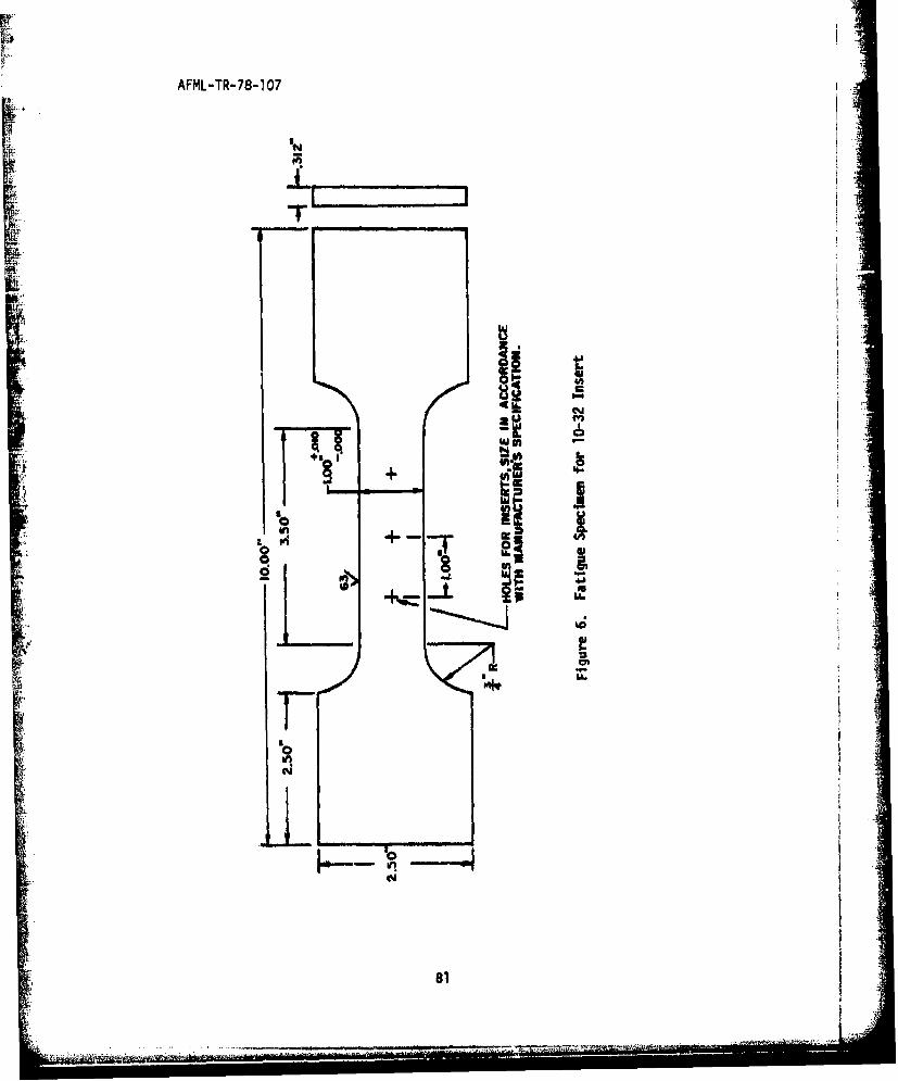
AFML-TR-78-107
-4b-
U+
L'6
b"
,~81
'-i- . .. I ~i n *, . . .

AFML-TR-78-107
•...
gz00
NC
- - 1
Zo G
4c
INn
"-o-
IN.
82
• -•i .. • .,• t °>' • " • •' ° , .. . . . . .. . .• - i I.. . . .. ...

AFML-TR- 78-107
LU **
W t
+ •
IMPF °got o
LA.
83
LL
83

r
AFML-TR-78-107
w
w
w VIK' IC- en
I-
L
C
I-Eu
I�i I VI
'p.
I-VII O�hS..
84
'4 -.

AFML-TR-78-107
41,
L.e.
858
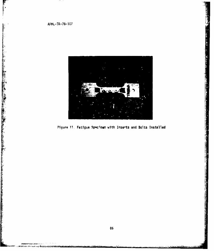
Vr!
AFML-TR-78-107
Figure 11. Fatigue Spacimen with Inserts and Bolts Installed
86

AFML-TR-78-1 071
Figure. 12. Fatigue Specimen in MTS Universal Test Machine
87

AFML-TR-78-107
L II
LZ
F4
U
L•
dI
I!
88

AFML-TR- 78-107
.W anivisNi ayivaill
aS OTIVISNI 'II N4V7
1 0
urivits~i 'iwav
O3~FIVLS41
2-I11V1StNI 'Noll L4NO
~U44A
GMI I MO01 0 1
00OT X RflIMV 01 S~1IAU
89

AFML-TR-78-1 07
~7a3TIvISNI Nl-Aooxf)
- ___ U~11VISNI lyIvO-'11
ag' M VIS NI I~'f47H4
r~~ U~CZIVISNI WY)IO
0I
ZY1S IIWN
____C3 1 Y1imiSol- INA
acIV'IvJsNI NVSOV
--. . . . . . . . . .- WV%
U311ITYSNI MIAV"M n
aa'lYJ.sNi qmIvNA)
Vii
90

AFML-TR-78-1 07
F aZ'IIYISNINIdl-AOO'd) 0
UrIFY.LSNI IXAV
O2TZVISNI IIOD-f3 j (
UZTIYLSK4I wU4v *
CL911VISKI MUVOI
OOrrnsu axinzv
L91I.l

AFML-TR-78-107
aSTIVISNI MIIOIV
01
UaTiansm4 Nivai
4- CMIN %U______
asivis. 1F.,.12
aaI1SINI Way ±
,U .
CRTNIVIN Y~
000! x RUflIIVA 01 s3aIDJm
92

AFML-TR-78-107
I, . .o
I I i II
0I 0 0
3/8-24 1/4-20 10-32
Figure 18. Insert Pull Out Specimens and Corrosion Specimen
931

AFML-TR-78-1 07
4-a
t-
'4J
4-
94-

AFML-TR-78-107
FCoC
00
N020
oQ5

AFML-TR-78-107
W
Cr
pw4-
AA i,
ci
LA.
96A
. . . . .. . ..

AFML-TR-78-107
Lo
Groov-ipn Long-Lok
Figure 22. Close-up of Fatigue Failure of Specimens with Groov-Pin andLong-Lok 10-32 Size Inserts. Inserts Installed by Manufacture.
, 1h, 'Torqued Bolts in Insert During Tests.
Rosan Tridair Hell-Coil
Figure 23. Close-up of Fatigue Failures of Specimens with Rosan, Tridair,and Heli-Coil 10-32 Size Insert. Inserts Installed by Manufacture.Torqued Bolts in Inserts During Tests.
97

AFML-TR-78-107
Long-Lok Rosan Kaynar
Figure 24. Close-up of Fatigue Failures of Specimens with Long-Lok, Rosan,and Kaynar 10-32 Size Inserts. Inserts Installed by AFML.Torqued Bolts in Inserts During Tests.
LI
STridalr Groov-Pin
Figure 25. Close-up of Fatigue Failures of Specimens with Tridair andGroov-Pln 10-32 Size Inserts. Inserts Installed by AFML.Torqued Bolts in Inserts During Tests,
98

AFML--TR-78-107
Helli-CoilIFigure 26. Close-up of Fatigue Failure of Specimen with Heli*'Coil Insert.
Insert Installed by AFML. Torqued Bolts in Insert During Test.
Rosan Groov-Pin
Figjure 27. Close-up of Fatigue Failure of Speciwens with, Rosan and Groov-Pin1/4-28 Size Insert. Inserts Installed by Manufacture. TorquedBolts in Insert-ý During 'rests.

AFML-TR-79-1 07
Tridair Long-Lok
Figure 28. Close-up of Fatigue Failures of Specimens with Tridair andLong-Lok 1/4-28 Size Inserts. Inserts Installed by Manufacture.Torqued Bolts in Inserts During Tests,
24
Figure 29. Close-up of Fatigue Failure of Specimens with Heli-Coil 1/4-28Size Inserts. Torqoed Bolts in Inserts During Tests.
1 00

AFML-TR- 78-I 07
Hel i-ColFigure 30. Close-up of Fatigue Failure of Specimens with Hell-Coil 1/4-28
Size Insert. Inserts Installed by AFML. Torqued Bolt InInserts During Test,
Rosan Groov-Pin Long-Lok
Figre 1.Close-up of Fatigue Failure of Specimens with Rosan, Groov-Pin,Figre 1.and Long-Lok 1/4-28 Siz~e Insert. Inserts Installed by AFML.
No Bolt in Inserts.
101

AFML-TR-78-1 07
I30
Figure 32. Close-up of Fatigue Failure of Specimens with Hell-Coil,
Tridair, and Kaynar 1/4-28 SIze Inserts. Inserts Installedby AFML. No Bolt in Inserts.NI
Figure 3.3. Close-kip of Fatigu~e Failures of Specimens with No~ Inserts.1/4 Inch Dliameter Holes.
102
..... .... ... ... ... .... .. ..... ..

AFML-TR- 18-107
141Figure 34. Close-up of Fatigue Failure of Specimen with Rosan and
Kaynar 1/4-28 Size Inserts. Inserts Installed by AFML.Torqued Bolts in Inserts During Tests,
Figure 35. Close-up of Fatigue Failures of Specimens with Groov-Pinand Trldair 1/4-28 Size Inserts, Inserts Installed byAFML. Torqued Boltý, in Ins3erts During Tests.
ifI
6 6 ... ...... ..

AFML-TR-78-107
IL1/4 28
Figure 36. Close-up of Fatigue Failure crf Specimens with Long-Lok Insert.Inserts Installed by AFML. Torqued Bolts in Inserts DuringTest.
Figure 37. Close-UP of Fatigue, Failures of Specimens with Long-Lok andHe~li*Coi1 3/8-24 Size Inserts. Inserts Installed by AFML.Torqued Bolts in Inserts During Tests.
1 04

AFML-TR-78-107
441
'01
Figure 38. Close-up of Fatigue Fracture of Specinmens with Tridair 3/8-24Size Insert. Insert Installed by AFML. Torqued Bolt in InsertsDuring Test.
Figure 39. Close-up of Fatigue Failures of Specimens with Groov-Pin andRosar, 3/8-24 Size Inserts. Inserts Installed by AFML. TorquedBolts in Inserts During Tests.
105

AFML-TR-78-1 07
Figure 40. Close-up of Fatigue Failure of Specimens with Tridair andGroov-Pin 1/4-28 Size Insert. Inserts Installed by Manufacture.
Figure 41. Close-up of Fatigue Failures of Specimen with Rosan and Tridair3/8-24 Size Inserts, Inserts Installed by Manufacture. TcirquedBolts in Inserts During Tests.
106

AFML-TR-78-107
Figure 42. Close-up of Fatigue Failure of Specimens with Groov-Pin SizeInserts. Inserts Installed by Manufacture. Torqued Boltsin Inserts During Test.
Figure 43. Close-up of fatigue Failure of Specimens with Hell-Coil 3/8-24Size Inserts. Inserts Installed by Mlanufacture. Torqued Boltsin Inserts During Test

AFML-TR- 78-1 07
Figure 44. Close-up of Fatigue Failure of Specimens with Hell-Coil andRosan 1/4-28 Size Inserts. Inserts Installed by Manufacture. I-No SlinInserts.
k I
Figure 45. Close-up of Fatigue Failure of Specimens with Long-Lok 1/4-28Size Inserts. Inserts Installed by Manufacture. No Boltsin Inserts.
108
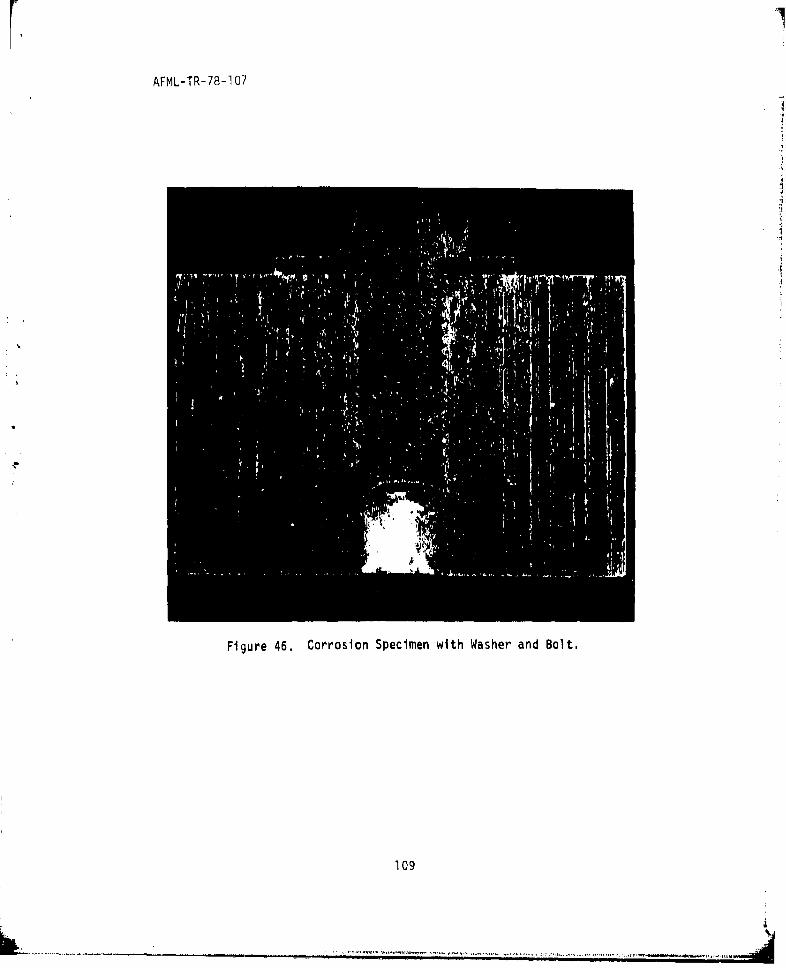
AFML-TR-78-1 07
Figure 46. Corrosion Specimen with Washer and Bolt.
109

AFML-TR-78-107
Ii
2 €'
Y via%_DATE:Figure 47. Corrosion Specimen
110

AFML-TR-78-107
17, WI
161
19V N
1111 IN ! iiii i i iii iii i i lil ill lll 1111 1 1 111 1111 11 111 1 111 11 11 1
I AC

AFML-TR- 78-107
K Is
4SOT
K112

AFML-TR-78-107
EN4
I../I
'I'
Figure 50. Corrosion Specimen
11~3

AFML-TR--73--107
1144
.. .... .

AFML-TR-78-1 07
IN
Figure 52. Corrosion Specimenn
Ij

AFML-TR-78-1 07
W'.
_ IIhi.
.~. IU
(Io
d~I'1W
u 0

AFML-TR-78-1 07
Figure 54. Corrosion of Parent Material Surfdcoe
117

IIAFML4R-78-107
I.-
L
I
I I
_____ DATLW
Figure 55. Corrosion Specimen with Bolt Removed
118

AFML-TR-78-1 07
00AwIFigue 5. Coroson pecien fterClenin
Figue 5. Coroson pecien fterClenin119

AFML-TR-78-1 07 -
Figure 59. Corrosion Specimen after Cleaning
120
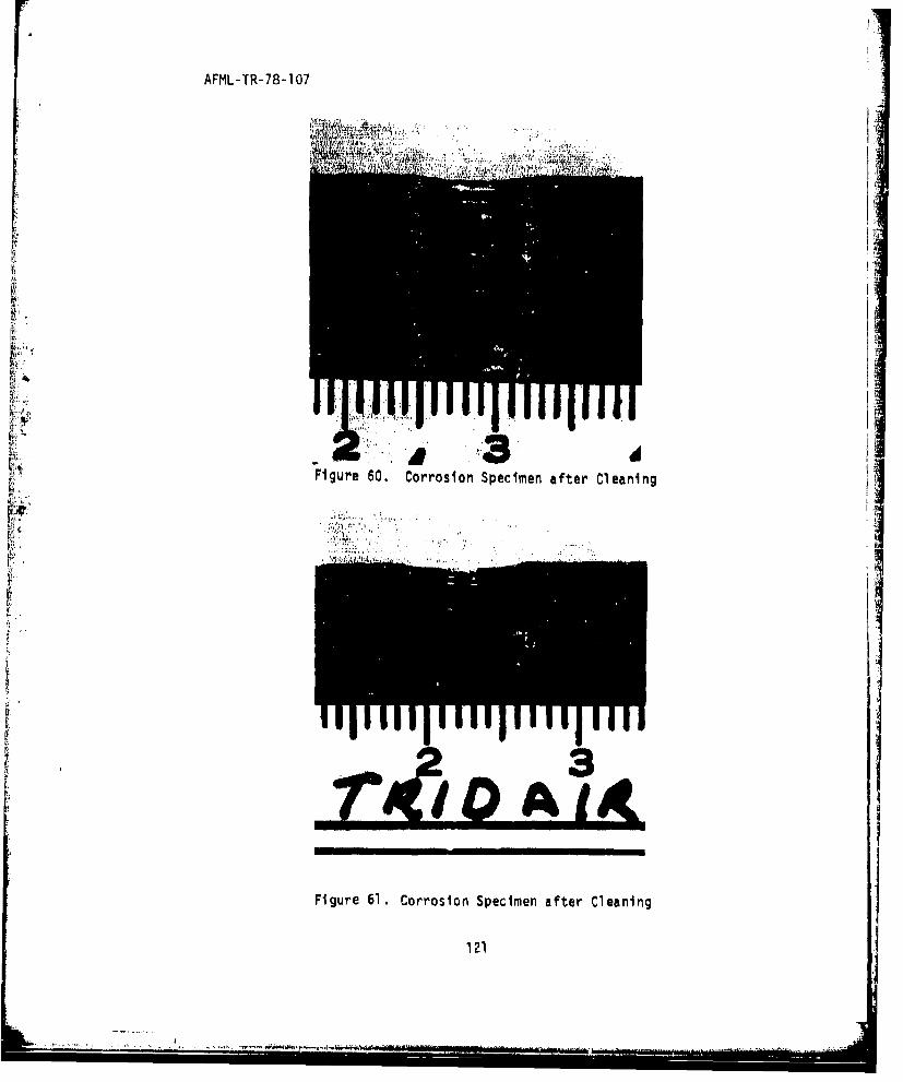
AFML-TR-78- 107
MI.,
Figure 60. Corrosion Specimen after Cleaning
121

AFML-TR- 78-107
Figure 62. Corrosion Specimen after Cleaning
122

.....7.. ...'AFML-TR-78-1 07
APPENDIX
123

AFML-TR-78-107
INTRODUCTION
A statistical analysis of the engineering test data was made by theUniversity of Dayton Research Institute. This analysis was undertakento determine if there is a significant difference In the engineeringtest data obtained on threaded inserts supplied by several different
insert manufacturers. Analysis of variance was used as the basic tool
in the analysis of the experimental data.
124

AFML-TR-78-107
I.SECTION 2
SUMMARY OF RESULTS
Average fatigue lives for manufacturers displayed significant
differences for each bolt size but the differences were not consistentover all three sizes. The installer (AFML or manufacturer) did notaffect average fatigue life in the 10-32 and 1/4-28 bolt sizes butmanufacturer installed Inserts displayed larger average lives in the3/8-24 bolts for some insert types. The fatigue lives with bolt
inserted were significantly larger than those with Inserts but no bolt.The average fatigue lives for inserts without bolts were not signifi-
cantly different from specimens with hole but no insert installed.
2.2 BREAKAWAY TORQUE
In general, a larger breakaway torque is required to loosen the
bolts after fatigue cycling than before. The difference in breakaway
torque (before and after cycling) depends on the manufacturer and in the1/4-28 bolts also depended on the installer.
2.3 AXIAL STRENGTHS
Average axial strengths displayed significant differences in the1/4-28 and 3/8-24 size specimens. In the 1/4-28 sized specimens, themanufacturers could be divided into two strength groups with Rosen,Tridair, and Long-Lok having the greater average axial strength. Inthe 3/8-24 sized specimens, the Kaynar inserts had a smaller average
strength than the others.
125
S. . .... •U

AFML-TR-78-107
2.4 LOCKING AND BREAKAWAY TORQUE TESTS
The reduction in locking and breakaway torques after repeat bolt
insertions averages approximately 35% at the 15th cycle. On the average
about 64% of this reduction occurs during the first five cyclas. Differ-
ences due to installers were small in comparison to differences due to
specimen variation tested under identical conditions.
$.
126

AFML-TR-78-107 A
SECTION 3
STATISTICAL ANALYSIS
Data from three types of tests were subjected to statistical analyses.
These were fatigue tests with the dependent variables of cycles to failure
and breakaway torques after cyclic loading; axial strength tests; and the
locking and breakaway torque tests. The analyses of the data from these
three types of test are presented in the following paragraphs. Analysis
of variance was used as the basic tool in the analysis of the experimental
data. The fatigue life tests on 1/4-28 size bolts will be presented in
detail to show the application of the analysis of variance technique to-i experimental data.
3.1 FATIGUE TESTS
Two types of data were collected for analysis during the fatigue
tests: number of cycles to failure and breakaway torque before and
after fatigue cycling.
3.1.1 Life Tests
The objective of the analysis of the fatiguo life data was
to ascertain if significant results' were obtained from the different
manufacturers; from the different installers; And from the specimens
without inserts, the specimens with inserts only, and the specimons with
inserts and bolts. To test these hypotheses constant amplitude fatigue
tests were run at R w 0,1 and maximum stress of 50% of ultimate for each
of three specimen thicknesses (bolt sizes). Note that each specimen
contains three inserts and the fatigue test terminated at the failure
of any one of the three, The location within the specimens of the
failing insert occurred at random among the three possible locations.
Fur the 10-32 and 3/8-24 bolt size specimens, the fatigue tests were
only conducted with bolts inserted. For the 1/4-28 size, specimens
were tested with and without bolts and somA specimens were also tested
127
•W

APML-TR-78-107
without Inserts (smooth and threaded). For each manufacturer-sizecombination half of the inserts were installed by the manufacturer and
. half by the APML. Since all combinations of the experimental conditionswere tested for a bolt size, the data comprise of factorial experiment.
Table 59 presents the data layout for the 1/4-28 bolt size fatiguetests when viewed In factorial format. (Since this data. Is simply arearrangement of the data in Tables 26-33 similar tables for the otherexperiments will not be presented.) The statistical model for theanalysis of the data of Table 59 is given by
YiJkl M i + IJ +'MIiJ + Bk + MBik + IBjk + MIBijk + 5ijkl
where:
.ijkl " observed cycles to failure
P voerall average
MI * differential effect of manufacturer I
aI a differential effect of installer I (AFML or MFG)
Miij * differential Joint effect of MI and I
Bk a differential effect due to presence or absence of bolt
MBik * differential joint effect of MI and Bk
IBJk a differential Joint effect of I and Bk
2MIBik, differential Joint effect of M1, I, and Bk
""ijkl- random error- for the Ith replication of the experimentalcondition defined by Mi, I, and lk.
It is assumed that ,ijkl are independent, normally distributed randomvariables with zero mean and common variance, 0a. All uncontrolledsources of variation in the experiment are measured in the estimate
128 -
A I~,
ii
AFML-TR-78-107
,of a The analysis of variance (as applied here) is a technique for
testing whether the differential effects are significantly differentSfrom zero. For example, If the installer does not affect fatigue life,the differential effect due to Installer should be zero and the I termscan be eliminated from the model. For those differential effects which
are significantly different from zero, further statistical tests, basedon the estimate of a (the standard error) are available to Identifyspecific significant differences. The analysis of variance results for
an experiment are summarized in an analysis of variance table. Table60 summarizes the analysis of variance for the data of Table 59, In
these experiments the F ratio is the ratio of the mean square for a
source of variation to tho random error mean square. Large F ratios
indicate significant, effects where largeness is defined by degrees ofIfreedom and level of significance desired for the tests and can beascertained from tables in most texts on statistics. For these experl-
mints, the level of significance (the probability of rejecting the nullhypothesis when true) was fixed at 0,05. Thus, it was concluded that
the presence or absence of the bolt significantly affects fatigue life
and that the fatigue lives from the different manufacturers are signifi-cantly different. The effect due to Installer was not significant.Figure 63 plots average life for each manufacturer by bolt combination
with 95% confidence limits for the mean lives with bolt inserted. Theaverage life for the Hell-Coil inserts with bolts were significantlylonger than those of the Torkon and Groov-Pin. The other differencesamong the average lives with bolts were not significant.
Three hole conditions were fatigue tested without inserts (Table
25). An analysis of variance indicated that there were no significant
differences between average lives of the smooth and threaded holes,The composite average of all 15 specimens was 31,400 cycles with a
standard deviation of 4,180 cycles. Thus, 95% confidence limits on
mean life without Inserts are given by the interval 31,400 + tO 9 5 , 14(4180)/JW
129

AFML-TR-78-107 d.
or (29000, 33,800). Since the composite average of the fatigue lives
with insert only was 31,600 cycles, there was not a significant differencebetween the specimens with and without inserts.
'In the fatigue tests of the 10-32 and 3/8-24 bolt sizes, all tests
were performed with bolts. The analysis of these data could only evaluate
the manufacturers and the installers.
Table 61 presents the analysis of variance table for the 10-32bolt size experimont. The only significant effect was that due to the
manufacturer. Figure 64 presents the average life for each manufacturer
with 95%.,confidence limits. The Hell-Coil inserts had significantly
longer average life than all except the Groov-Pin Inserts for this bolt
length. The Groov-Pin average life was significantly longer than allexcept the Tridair insert . The Torkon insert had a significantly Ishorter average life than all other inserts for this bolt size.
The analysis of variance table for the 3/8-24 bolt sizes is pre-
sented in Table 62. For this bolt size, significant differences existed
among the manufacturers, between the installers, and the differences dueto Installers were not consistent among the different insert manufacturers.
Average life for each combination of installer and manufacturer is pre-sented in Figure 65. For the Rosan, Tridair, and Groov-Pin inserts the
manufacturer installed specimens had longer average lives than the AFML
specimens. The differences in average life between manufacturer and
AFML installed specimens were not significant for the other brands ofinserts. The manufacturer Installed specimens had significantly longer
average lives than the AFML installed specimens. Specific comparisons
between any manufacturer-installer pair can be made by declaring theaverage difference statistically significant (at the 95 percent levelof confidence) if it exceeds 8.4K cycles.
130
........... ...
il ,,°
AFML-TR-78-107
•I 3.1.2 Breakaway Torques After Cyclic Loading
To determine if cyclic loading had a significant effect on
breakaway torque, measurements were taken on all inserts before thefatigue tests and on the unfailed inserts at the conclusion of the fatiguetest (Tables 3 through 23). The difference between the dfter fatiguecycling breakaway torque and the before from the unfailed inserts providedthe measure which was used in the analysis of these data. For each boltsize, the torque differences were analyzed for differences due to insertmanufacturers or insert installers and whether or not significantly more
torque was required after cyclic loading.
Table 63 presents the analysis of variance table for thebreakaway torque differences measured on the 10-32 specimens. The
average differences due to manufacturers contained significant differ-ences but the average differences did not depend on installers. Figure66 displays the average difference for each manufacturer with 95 percentconfidence limits for the means. The average differences in breakaway
torques were significantly less for the Kaynar and Rosan Inserts thanfor the others. Further, the differences in breakaway torques betweenbefore and after fatigue testing were not significantly different forthe Kaynar and Rosan inserts but the others required greater torqueafter fatigue cycling.
The analysis of variance table for the differences inA breakaway torque of 1/4-28 size bolt fatigue tests is presented in
Table 64. For these data the manufacturer and joint manufacturer byinstaller effect were significant. The average before minus aftertorque measurement for the manufacturer by installer combinations are
presented in Figure 67, For these bolt size specimens, the AFML
1l

AFML-TR-78-107
installed Rosan inserts required signtficantly greater breakaway after
fatigue cycling than did the manufacturer installed sosan Inserts. TheKaynar, Long-Lok, Torkon, and AFML installed Groov-Pin Rosen installed
inserts required equivalent torques before and after fatigue cycling.
The analysis of variance table for the 3/8-24 bolt size
breakaway torque bolt differences is presented In Table 65. Thedifference between manufacturers and installers are not statisticallysignificant for this bolt size specimen. Note, however, thaý thesedata exhibitad significantly more variability (larger standard error)
than did those of the torque differences in the narrower specimens.*• Figure 68 presents average difference for each manufacturer (with confi-* dence limits) even though the manufacturer differences are not signifi-
cant. Note that for all manufacturers significantly grdater breakaway
torque was required after fatigue cycling than before.
,-,• ,%.2 AXIAL STRENGTH TESTS
Tensile strength pull out tests were conducted in accordance withthe factorial e):periment which permits comparison of axial strengthsL_ for the intert manufacturers and Installers for each of the threespecimen thicknesses (Table 35). This section presents the analyses
of these data.
Table 66 contains the analysis of variance table for the axial
strength tests of the 10-32 size specimens. There were no differencesin average strength among the manufacturers or between the Installers.However, differences between installer-manufacturer average strengthcombinations for the Kaynar and Grouv-Pin Ir,serts as compared to the
Long-Lok inserts produced a significant Joint effect. This can beseen In the plot of average strengths for manufacturer-installer combina-tions of rigure 69. NJote tliat the differences in the average strengthsfor the Installers of any one insert are not significant.
1j,3

AFFKý-TR-78-1 07
The analysis of variance table for the 1/4-28 axial strength
tests is presented In Table 67. Only the manufacturir effect was
significant and average strengths for each manufacturer with 95 per-
cent confidence limits is presented in Figure 70. The 1/4-28 inserts
from Rosen, Tridair, and Long-Lok had significantly greater averagestrengths than the others.
Table 68 presents the analysis of variance vible for the axial
strength tests in 3/8-24 size ipecimens. The manufacturer-installer
joint effect was significant as well as the differences in average
strengths among the manufacturers. Figure 71 preserts average axial
strengths ror these thick specimens. The Kaynar ir.,trt specimens had
significantly less average strength than the others while the Torkon
specimens, manufacturer installed displayed significantly greater
- strength than the other combinations. The Joint effect is due to tho
greater average strengths for the Torkon and Groov-Pin inserts when
installed by the manufacturer than by AFML while the Kaynar AFML In-
stalled inserts had greater strength than the Kaynar installed inserts.
3.3 LOCKING AND BREAKAWAY TORQUE TESTS
To investigate the wear resulting from repeated engagement of
bolts In the fasteners, three inserts from each manufacturer-installer- I
bolt size combination were cycled through 16 engagements and disengage-
ments of bolts. The resulting data (Tables 43-57) displayed minor
differencet between installers as compared to sample variation of
replicate conditions, Figures 72 through 78 display average torque
for each cycle of each manufacturer by bolt size combination. At the
15th cycle, locking and unlocking torques are reduced by an average
of 36 percent of their orginal values (first cycle). As can be seen a
on the figures, much of this reduction generally occurs during the
first few cycles. Table 69 presents the percent reduction of average
torques for each manufacturer-bolt size combination at the 5th, 10th,
and 15th cycle.
A
133
+i! I- '-.' -P N.

AFML-TR-78-1 07
TABLE 59
FATIGUE LIVES FROM 1/4-28 TESTS
(K Cycles to Failure)
ManufacturerKAY C TI LL TOR OP_ _
With A ,ML 49.5. 43.2 43.4 45.9 39.9 37.6 40.7Bolt 39.8 39.0 46.4 45.3 52.8 38.5 29.1
33.6 61.;e 58.9 47.1 52.1 35.9 39.0
MFG 43.6 48.1 43.5 37.4 41.8 35.9 45.4
33.0 36.9 53.8 52.8 34.8 37.3 24.7
45.5 50.2 49.5 44.3 33.7 37.5 32.9
With- APML 24.3 32.7 30.0 41.4 28.6 29.0 25.?outB~1t 32.4 33.5 25.5 33.5 37.7 28.2 29.5
31.1 31.3 35.9 31.5 30.2 27.8 22.8
MFG 27.4 50.3 34.5 27.8 31.7 26.5 25.4
44.1 30.5 32.1 38.3 29.5 24.1 29.335.0 50.8 39.6 35.1 28.0 24.4 27.2
134

AFML-TR-78-107
TABLE 60ANALYSIS OF VARIANCE TABLE FOR FATIGUE
LIVES FROM 1/4-28 TESTS
Source of Degrees of Meann FVariation Freedom Square Ratio
Manufacturer(M) 6 217.20 6.14 SignificantInstallers(I) 1 0.63 0.021 6 41.83 1.18
Bolt (B) 1 2489.56 70.34 SignificantB 6 27.37 0.77
IB 1 108.12 3.06MIB 6 25.68 0.73Random error 56 35.39Total 83
Standard error - 4 - 5.95 (K cycles)
TABLE 61
ANALYSIS OF VARIANCE TABLE FOR FATIGUELIVES FROM 10-32 TESTS
Anurceof Degrees of Mean FVariation Freedom Square Ratio
Manufacturer 6 881.8 15.3 SignificantInstaller 1 89.2 1.55MI 6 43.8 0.76Random error 28 57.6Total 41
Standard error - . 7.59 (W. cycles)
135

4 ~f,
AFML-TR-78-107
TABLE 62
ANALYSIS OF VARIANCE TABLE FOR FATIGUELIVES FROM 3/8-24 TESTS
-•::i Sorce--of Degrees of Mean FI:Source of Fii o Ma
- Variation Freedom Square Ratio
Manufacturer 6 177.5 9.76 SignificantInstaller 1 174.0 9.57 SignificantMI 6 109.3 6.01 SignificantRandom error 28 18.19Total 41
Standard error - vl - 4.27 (K cyclels)
TABLE 63
ANALYSIS OF VARIANCE TABLE FOR BREAKAWAYTORQUE DIFFERENCES - 10-32 FATIGUE TESTS
Source of Degrees of Mean FVariation Freedom Sauare Ratio
Manufacturer 6 170.4 3.94 SignificantInstaller 1 136.3 3.15MI 6 60.4 1.39Random error 70 43.3Total 83
Standard error - v I- 6.6 in.-lbs.
136

k}
AFML-TR-78-107
TABLE 64 jANALYSIS OF VARIANCE TABLE FOR BREAKAWAYTORQUE DIFFERENCES - 1/4-28 FATIGUE TESTS
Source of Degrees of Mean .Variation Freedom Square Ratio
Manufacturer 6 1311.6 11.12 Significant* Installer 1 5.79 0.05
M1 6 386.4 3.28 SignificantRandom error 68 117.9
Total 81
Standard error v dT7r' - 10.86 in.-lbs.II"TABLE 65
ANALYSIS OF VARIANCE TABLE FOR BREAKAWAYTORQUE DIFFERENCES - 3/8-24 FATIGUE TESTS
Miuce Of begrees of- -mean 7T*Variation Freedom Square Ratio
Manufacturer 6 6031.2 1.86Installer 1 106.1 0.03MI. 6 6584.5 2.03Random error 68 3245.1Total 81
Standard error V 3245. 57.0 in.-lbs.
137 I X.,

AFML-TR-78-107
TABLE 66
ANALYSIS OF VARIANCE TABLE FOR AXIALSTRENGTH - 10-32 SIZE SPECIMENS
Source of Degrees of Mean FVariation Freedom Square Ratio
Manufacturer 6 67,000 0.70Installer 1 191,000 2.00MI 6 310,000 3.25 SignificantRandom orror 28 95,000Total 41
Standard error * - 308 lbs.
TABLE 67
ANALYSIS OF VARIANCE TABLE FOR AXIALSTRENGTH - 1/4-28 SIZE SPECIMENS
Source of Dgrees of Mean Y •Variation Freedom Square Ratio
Manufacturer 6 4,267,000 15.13 SignificantInstaller 1 144,000 0.51
141 6 117,000 0.41Random error 28 282,000Total 41
Standard error w - 530 lbs.
138
~ !t~fl-P. O.~-~- -

AFML-TR-78-107
I!
TABLE 68
ANALYSIS OF VARIANCE TABLE FOR AXIALSTRENGTH - 3/8-24 SIZE SPECIMENSSource o. Degre s of Mean Fvari:ation ?roadm Squýare Ratio
Manufacturer 6 31,942,000 34.16 Significant
Installer 1 3,691,000 3.94MI 6 5,884,000 6.29 SignificantRandom error 28 935,000Total 41
SI'iStandard error - - 967 lbs.
139

AFML-TR-78-107
TABLE 69
PERCENT REDUCTION OF AVERAGE LOCKINGAND BREAKAWAY TORQUES
Size ManufaoturerG .. _-_....._5Ro,,n 0_- -
10-32 Kaynar 2 28
Roman 23 39 41iHeli-Coil 26 29 31
Tridair 40 33 39
Long-Lok 21 33. 33STorkon 22 29 41
OGoov-Pin 37 48 49
1/4-28 Kaynar 17 20 2323,Roman is 23 23Heli-Coil 24 32 36Tridair 5 10 11Long-Lok 15 22 26
Torkon 28 42 45Groov-Pin 40 41 45
3/8-24 Kaynar 21 27 32Rgn7 11 3.3
Heli-Coil 21 35 42Tridair 23 39 42
_Long-Lok 12 26 36
Torkon 26 40 46Groov-Pin 40 67 69
140
... . . .......

AFMI.-TR-78-1O7
Incm
.g ..
3C 40.
3cj
fil 15.1&
141~

[, AFML-TR-78-107
•~ ~ ~ ~ ~ ~~a OA•'" ... l"' ..
K MCD
Im
I-
14
.lU' a,
•!..
4-
-0 4
•.I
:' 142!

,AFML-TR-78-107
.4-
fl~ InILI.f.n
~K o
143j
....... ......

AFt4L-TR-78-1O7
Inio XV9VOIO-JA144~

AFML-TR-78-1 07
- I-A
U-
IL-
vs
om(sqlul) ouej~o eb~3
146

AFML- TR- 78-107
411
LI6
14

AFML-Tk-73-1 07
0<
F C.
1471

AFML-TR-78-1 07
cc N
"IA
c-
L6
'n4'
....... ....

AFML-1 *R- 78-107
dIC
ccl
~149

AFML-TR-78-1 07
C.,',
co 4e
oLLJ
411IM6
(sql-ul)~~ ~ ~ ~ ~ aniB51Ou/u o BJA
150J

AFML-TR-78-1 07
C-
CY.
U-A
21 0-
Icm c
c t0~~#A4j-v
41
L6.
(sql-ul)~~ ~ aniwicNO~/Blol BJA

AFML-TR- 78-1 07
I4
L24IA
oo~ko
099-
... .. ...
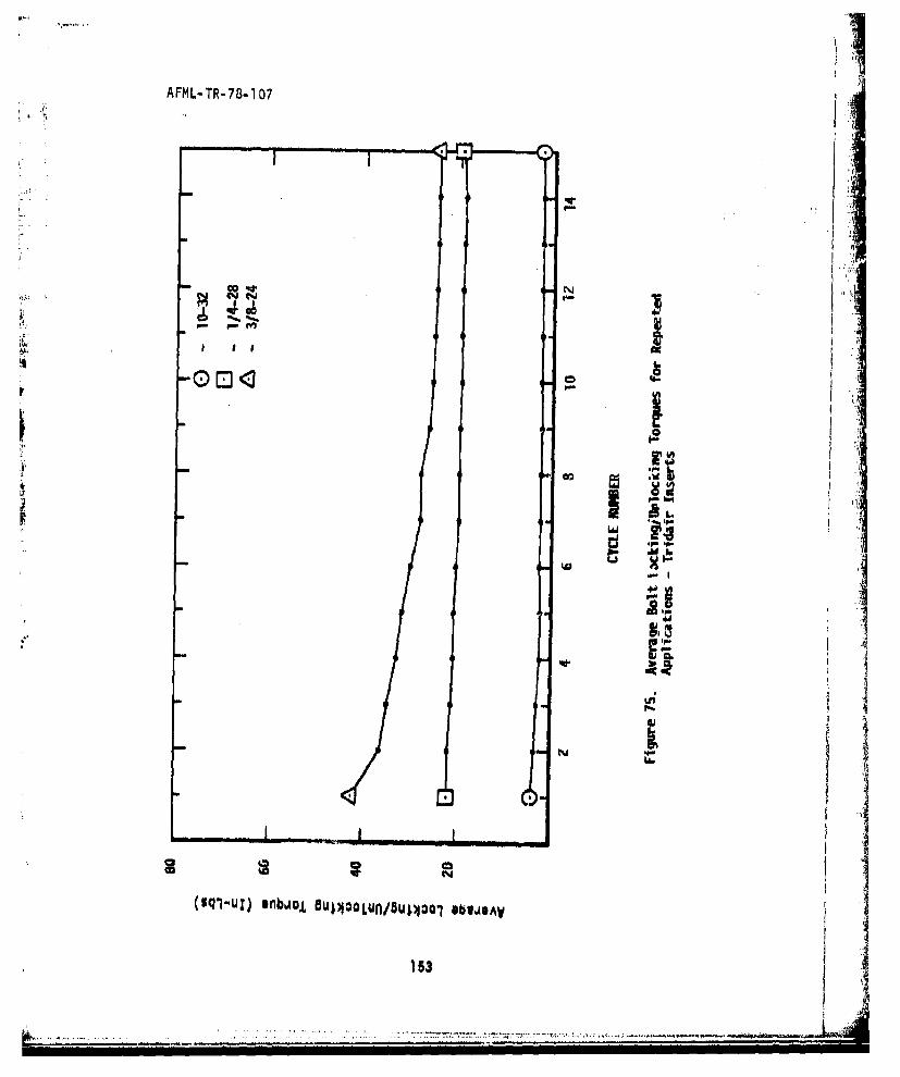
AFML- TR- 78-107
. .
F-
N �K.
I.r'a'
r F-C
I.lvi
�
IIILa.i
,� sp�
In '-I-I
LI;
N I* * ii
(uq�-uz) *nbAoJ, OUi2 oLUfl/8u�po1 *bw�eAv I153
I-

44
AFM-T-78-0
14 r4 X
22

AFML-T'R- 78-107
U-
C'hJ
4 1
we .
oo~ I-op..C 66
(sqlul) nb~o 54 OL~n54101 9SJV-
156~
.... ...

AFM4L-TR-78-1 07
* III
IA
ogod
(sql-ul) ~~~ ~ ~ 'U anilBIUu/Soo BJA
156Rintimn otial18 6708/3