Adafruit Proto Shield for Arduino - Adafruit Industries · PDF fileAdafruit Proto Shield for...
44
Adafruit Proto Shield for Arduino Created by lady ada Last updated on 2016-08-04 11:06:30 PM UTC
-
Upload
nguyendieu -
Category
Documents
-
view
228 -
download
1
Transcript of Adafruit Proto Shield for Arduino - Adafruit Industries · PDF fileAdafruit Proto Shield for...
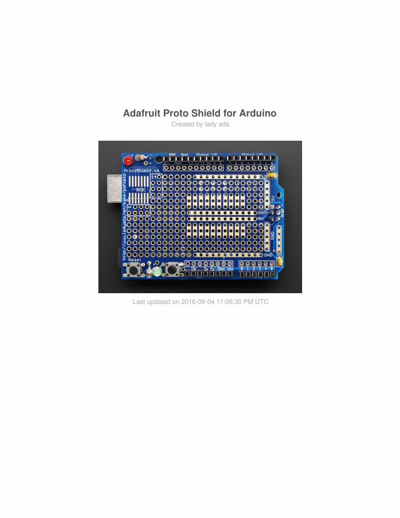
Adafruit Proto Shield for ArduinoCreated by lady ada
Last updated on 2016-08-04 11:06:30 PM UTC
2377
888
131313
1515222626
2931353841414141
Guide Contents
Guide ContentsOverviewMake it!
Lets go!
PreparationPrepTools
Parts listParts ListOptional parts
Solder it!Soldering with Stacking HeadersInstalling plain headersInstalling Extras
Installing Capacitors
Installing ButtonsInstalling LEDsSPI/ICSP Connector5-Pin power rail connectionsDownloadFilesSchematicFabrication Print
© Adafruit Industries https://learn.adafruit.com/adafruit-proto-shield-arduino Page 2 of 42

Overview
This prototyping shield is the best out there (well, we think so, at least), and now is evenbetter with Version R3 - updated for the most compatibility with just about all the Arduinos!
It works with UNO, Mega, Leonardo, NG, Diecimila, Duemilanove, and compatibleArduinos. Yun's and Arduino Ethernets have a chunky Ethernet jack that gets in the way ofstacking, you can use the stacking headers included and it will work, just doesn't sit niceand flat.
Check out these awesome specifications:
It has a nice standard 0.1"x0.1" prototying grid with big padsComes with Stacking headers and plain header, choose whichever you want whensoldering together
© Adafruit Industries https://learn.adafruit.com/adafruit-proto-shield-arduino Page 3 of 42

A IC pattern for adding DIP ICs up to 20 pinsPower rails down the middle and sidesA reset button and an extra general use button2 3mm general use LEDs, red and green, as well as 2 matching resistorsA pass-thru ICSP stacking header so you can stack any kind of shield on top, and/oruse an AVR programmerA surface-mount chip area for up to 14 SOIC size partsCompatible with tiny breadboardsEvery pin is brought out!Gold plated pads2 x 0.1uF capacitors on either side for extra power stability
Pair with a tiny breadboard for a cute stand-alone prototyping setup!
© Adafruit Industries https://learn.adafruit.com/adafruit-proto-shield-arduino Page 4 of 42

Larger breadboard for tons of working space!
© Adafruit Industries https://learn.adafruit.com/adafruit-proto-shield-arduino Page 5 of 42

2 LEDs and one button are availble for general purpose use!
© Adafruit Industries https://learn.adafruit.com/adafruit-proto-shield-arduino Page 6 of 42

Make it!
Lets go!
This is a very easy kit to make, just go through each of these steps to build the kit.
1. Tools and preparation (http://adafru.it/cEL)2. Check the parts list (http://adafru.it/cEM)3. Solder it (http://adafru.it/cEN)
© Adafruit Industries https://learn.adafruit.com/adafruit-proto-shield-arduino Page 7 of 42

Preparation
Prep
Learn how to solder with tons of tutorials! (http://adafru.it/aTk)Don't forget to learn how to use your multimeter too! (http://adafru.it/aZZ)
Tools
There are a few tools that are required for assembly. None of these tools are included. Ifyou don't have them, now would be a good time to borrow or purchase them. They are veryvery handy whenever assembling/fixing/modifying electronic devices! I provide links to buythem, but of course, you should get them whereever is most convenient/inexpensive. Manyof these parts are available in a place like Radio Shack or other (higher quality) DIYelectronics stores.
Soldering iron
Any entry level 'all-in-one'soldering iron that you might findat your local hardware storeshould work. As with most thingsin life, you get what you pay for.
Upgrading to a higher endsoldering iron setup, like theHakko FX-888 that we stock in
© Adafruit Industries https://learn.adafruit.com/adafruit-proto-shield-arduino Page 8 of 42

our store (http://adafru.it/180), willmake soldering fun and easy.
Do not use a "ColdHeat"soldering iron! They are notsuitable for delicate electronicswork and can damage the kit(see here (http://adafru.it/aOo)).
Click here to buy our entry leveladjustable 30W 110V solderingiron (http://adafru.it/180).
Click here to upgrade to aGenuine Hakko FX-888adjustable temperature solderingiron. (http://adafru.it/303)
Solder
You will want rosin core, 60/40solder. Good solder is a goodthing. Bad solder leads tobridging and cold solder jointswhich can be tough to find.
Click here to buy a spool ofleaded solder (recommended forbeginners) (http://adafru.it/145).
Click here to buy a spool of lead-free solder (http://adafru.it/734).
© Adafruit Industries https://learn.adafruit.com/adafruit-proto-shield-arduino Page 9 of 42

Multimeter
You will need a good qualitybasic multimeter that canmeasure voltage and continuity.
Click here to buy a basicmultimeter. (http://adafru.it/71)
Click here to buy a top of the linemultimeter. (http://adafru.it/308)
Click here to buy a pocketmultimeter. (http://adafru.it/850)
© Adafruit Industries https://learn.adafruit.com/adafruit-proto-shield-arduino Page 10 of 42

Flush Diagonal Cutters
You will need flush diagonalcutters to trim the wires andleads off of components onceyou have soldered them in place.
Click here to buy our favoritecutters (http://adafru.it/152).
Solder Sucker
Strangely enough, that's the
© Adafruit Industries https://learn.adafruit.com/adafruit-proto-shield-arduino Page 11 of 42

technical term for this desolderingvacuum tool. Useful in cleaningup mistakes, every electricalengineer has one of these ontheir desk.
Click here to buy aone (http://adafru.it/148).
Helping Third Hand WithMagnifier
Not absolutely necessary but willmake things go much muchfaster, and it will make solderingmuch easier.
Pick one uphere (http://adafru.it/291).
© Adafruit Industries https://learn.adafruit.com/adafruit-proto-shield-arduino Page 12 of 42
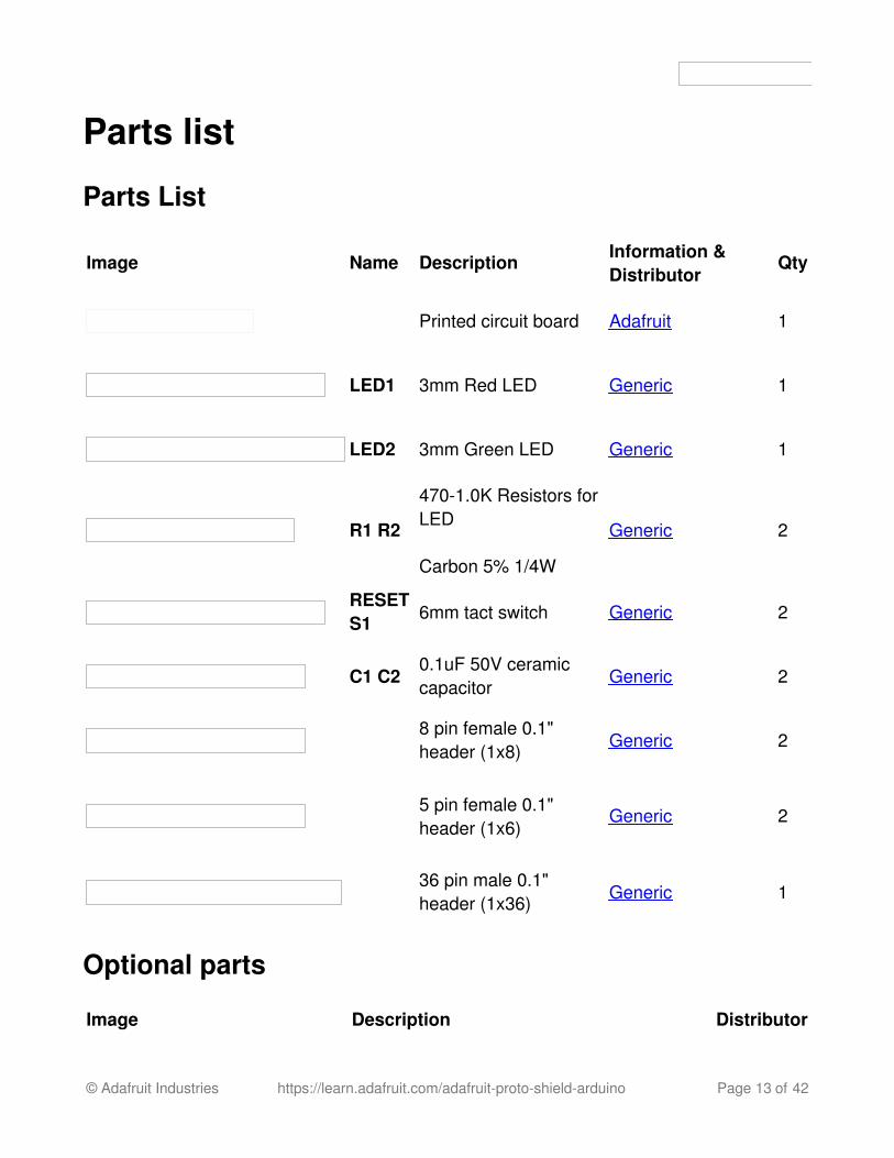
Parts list
Parts List
Image Name Description Information &Distributor
Qty
Printed circuit board Adafruit 1
LED1 3mm Red LED Generic 1
LED2 3mm Green LED Generic 1
R1 R2
470-1.0K Resistors forLED
Carbon 5% 1/4W
Generic 2
RESETS1 6mm tact switch Generic 2
C1 C20.1uF 50V ceramiccapacitor
Generic 2
8 pin female 0.1"header (1x8)
Generic 2
5 pin female 0.1"header (1x6)
Generic 2
36 pin male 0.1"header (1x36)
Generic 1
Optional parts
Image Description Distributor
© Adafruit Industries https://learn.adafruit.com/adafruit-proto-shield-arduino Page 13 of 42

Small breadboard (300 tie points).
This is a little more practical than the larger'standard' ones.
Adafruit
Tiny breadboard (170 tie points).
You can use the 5 pin female headers(1x5) a with 'tiny' breadboard as 'end rails.'
Adafruit
© Adafruit Industries https://learn.adafruit.com/adafruit-proto-shield-arduino Page 14 of 42
Solder it!Time to solder the kit together! If you've never soldered before, check the Preparation pagefor tutorials and more. (http://adafru.it/aZW)
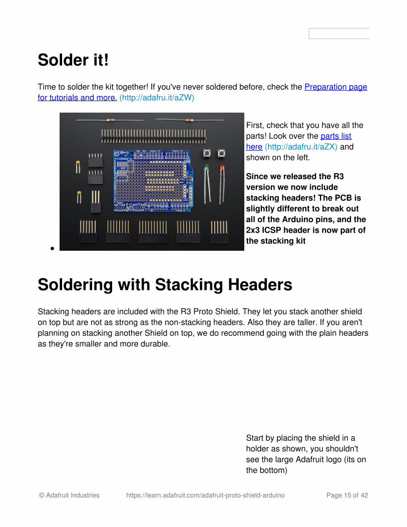
First, check that you have all theparts! Look over the parts listhere (http://adafru.it/aZX) andshown on the left.
Since we released the R3version we now includestacking headers! The PCB isslightly different to break outall of the Arduino pins, and the2x3 ICSP header is now part ofthe stacking kit
Soldering with Stacking HeadersStacking headers are included with the R3 Proto Shield. They let you stack another shieldon top but are not as strong as the non-stacking headers. Also they are taller. If you aren'tplanning on stacking another Shield on top, we do recommend going with the plain headersas they're smaller and more durable.
Start by placing the shield in aholder as shown, you shouldn'tsee the large Adafruit logo (its onthe bottom)
© Adafruit Industries https://learn.adafruit.com/adafruit-proto-shield-arduino Page 15 of 42

Then slide the 6, 8 and 10 pinheaders into the outside rows ofthe shield as shown. You willlikely have an extra two stackingparts, just put those aside fornow.
Now carefully plug theunsoldered headers into a spareArduino. Make sure all of thelong pins plug into the sockets onthe side of the Arduino. There willbe a gap between the shield andArduino and the Printed CircuitBoard will be loose
Flip over the Arduino and place itflat on the table so that the PCBsits flat against the stackyheaders and the stacky headersare flat against the table
© Adafruit Industries https://learn.adafruit.com/adafruit-proto-shield-arduino Page 16 of 42

Now from above, solder the twoend pins a stacky header to thePCB. You don't have to do agreat job soldering, just makesure it's tacked together.
© Adafruit Industries https://learn.adafruit.com/adafruit-proto-shield-arduino Page 17 of 42

Continue with the other header
© Adafruit Industries https://learn.adafruit.com/adafruit-proto-shield-arduino Page 18 of 42

Flip around and do the other twoheaders
Carefully remove the shield from
© Adafruit Industries https://learn.adafruit.com/adafruit-proto-shield-arduino Page 19 of 42

the Arduino and insert into yourvise with the ends of the stackingheader pointing up
Now that you have aligned the
© Adafruit Industries https://learn.adafruit.com/adafruit-proto-shield-arduino Page 20 of 42

stacky headers using an Arduinoit's easy to finish the job
Solder the remaining headerpins, including the two end pinsjust to make sure they are supersolidly soldered :)
© Adafruit Industries https://learn.adafruit.com/adafruit-proto-shield-arduino Page 21 of 42
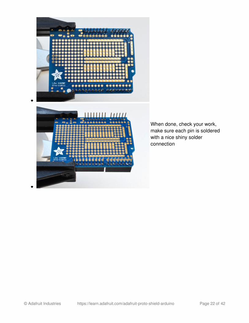
When done, check your work,make sure each pin is solderedwith a nice shiny solderconnection
© Adafruit Industries https://learn.adafruit.com/adafruit-proto-shield-arduino Page 22 of 42

Installing plain headersIf you want to install the plain header rather than stacking headers, follow this part:
Grab a plain Arduino
© Adafruit Industries https://learn.adafruit.com/adafruit-proto-shield-arduino Page 23 of 42
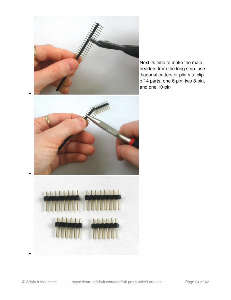
Next its time to make the maleheaders from the long strip. usediagonal cutters or pliers to clipoff 4 parts, one 6-pin, two 8-pin,and one 10-pin
© Adafruit Industries https://learn.adafruit.com/adafruit-proto-shield-arduino Page 24 of 42

Place the pieces of header intothe Arduino so the long pins arein the side sockets and the shortpins stick up
Place the PCB on top of theArduino so the short pins stickthrough the rows of pads oneither side
© Adafruit Industries https://learn.adafruit.com/adafruit-proto-shield-arduino Page 25 of 42

Solder all of the pads!
© Adafruit Industries https://learn.adafruit.com/adafruit-proto-shield-arduino Page 26 of 42

Check your work! Make sureevery point is nice and shiny
Installing ExtrasThe Proto Shield comes with some extras like 2 buttons, 2 capacitors and a red/green LEDset. These aren't essential but you may want to have them installed! Here's how you goabout doing it!
Installing Capacitors
There's two spots for 0.1uF
© Adafruit Industries https://learn.adafruit.com/adafruit-proto-shield-arduino Page 27 of 42

ceramic capacitors. These arenice little additions that help keepyour 5V power-supply clean
Place the two ceramic capacitorsin the spots shown. They aresymmetric so you don't have toworry about putting them inbackwards.
Bend the two little capacitor leadsout so that you can flip over thePCB without the caps falling out
© Adafruit Industries https://learn.adafruit.com/adafruit-proto-shield-arduino Page 28 of 42

Solder each of the 4 leads
Check your work!
© Adafruit Industries https://learn.adafruit.com/adafruit-proto-shield-arduino Page 29 of 42

Then clip the leads short using apair of diagonal cutters
Installing ButtonsThere's two optional buttons you can solder into your Proto Shield. One is connected to theArduino reset pin so you can quickly reset your Arduino. One is not connected to any pin,you can solder a wire from it to any other Arduino pin
Snap the two buttons into the topcorner of the PCB. They will snap
© Adafruit Industries https://learn.adafruit.com/adafruit-proto-shield-arduino Page 30 of 42

into place and sit flat against thePCB. They are symmetric so youcan insert them 'either way'
Flip over the board and solderthe 4 pads of each button
© Adafruit Industries https://learn.adafruit.com/adafruit-proto-shield-arduino Page 31 of 42

Check your work to make surethe solder points are nice andshiny...you're done!
Installing LEDs
Next it's time to place the two3mm LEDs. LEDs are directional,
© Adafruit Industries https://learn.adafruit.com/adafruit-proto-shield-arduino Page 32 of 42

and if you put them in backwardsthey wont work.
LEDs have a positive lead and anegative lead. The positive leadis longer.
On the Proto Shield PCB, you'llsee a circle indicating where theLED goes, and a small + sign.That's the indicator for which padgets the longer leg of the LED
Next to the red LED you canbend one of the 1K ohm resistorsover and insert it in the O-shaped silkscreen pads to the left
Resistors do not have a direction,so they can be installed eitherway.
© Adafruit Industries https://learn.adafruit.com/adafruit-proto-shield-arduino Page 33 of 42

Next insert the small green LEDbetween the two buttons. Like thered LED, check for the tiny +symbol on the PCB, aand placethe longer leg of the LED into thispad.
Then insert the other 1K resistorinto the 0- marked spot right nextto it
On the Proto Shield PCB, you'll see a circle indicating where the LED goes, and a small +sign. That's the indicator for which pad gets the longer leg of the LED
© Adafruit Industries https://learn.adafruit.com/adafruit-proto-shield-arduino Page 34 of 42

Bend out the leads of the LEDsand resistors so they sit flatagaint the PCB
Flip over the PCB in your vise
Solder in all the legs of the LEDsand resistors.
© Adafruit Industries https://learn.adafruit.com/adafruit-proto-shield-arduino Page 35 of 42
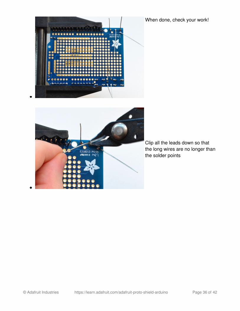
When done, check your work!
Clip all the leads down so thatthe long wires are no longer thanthe solder points
© Adafruit Industries https://learn.adafruit.com/adafruit-proto-shield-arduino Page 36 of 42

If you want to use the red andgreen LEDs or the generalpurpose button, simply soldersolid-gauge wire (~22awg isgood) into the large solder holesnear the device. Then you canplug the other end of the wire likea jumper into any of the femaleheaders. The two LEDs are tiedto ground through 1K or 1.5Kresistors. The button simplyconnects the jumper to groundwhen pressed (use an internal orexternal pull-up). Check theschematic on the download pagefor specific details.
SPI/ICSP Connector
© Adafruit Industries https://learn.adafruit.com/adafruit-proto-shield-arduino Page 37 of 42
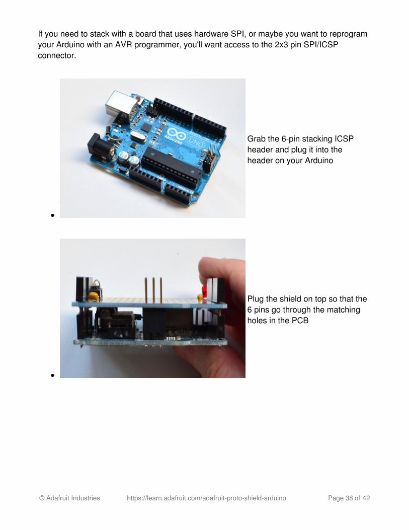
If you need to stack with a board that uses hardware SPI, or maybe you want to reprogramyour Arduino with an AVR programmer, you'll want access to the 2x3 pin SPI/ICSPconnector.
Grab the 6-pin stacking ICSPheader and plug it into theheader on your Arduino
Plug the shield on top so that the6 pins go through the matchingholes in the PCB
© Adafruit Industries https://learn.adafruit.com/adafruit-proto-shield-arduino Page 38 of 42

Solder all 6 pads
You're done!
© Adafruit Industries https://learn.adafruit.com/adafruit-proto-shield-arduino Page 39 of 42

5-Pin power rail connectionsIf you're using the proto shield with a tiny breadboard you may want to solder in the two 5-pin headers to the 5V and GND rails near the end of the Proto Shield, its pretty easy!
Place the two non-stacking 5-pinheaders into the matching slotson the right hand side of thePCB. Use tape to keep them inplace
Flip over the board. Use moretape if you need to keep theheaders from sliding out
© Adafruit Industries https://learn.adafruit.com/adafruit-proto-shield-arduino Page 40 of 42

Solder all the pads!
Check your work, make sure allthe pins are solidly attached
© Adafruit Industries https://learn.adafruit.com/adafruit-proto-shield-arduino Page 41 of 42

© Adafruit Industries Last Updated: 2016-08-04 11:06:29 PM UTC Page 42 of 42

Download
FilesEagleCAD PCB Files on GitHub (http://adafru.it/pBu)Fritzing object in Adafruit Fritzing library (http://adafru.it/c7M) (schematic view notfunctional, use for diagramming only!)
Schematic
Fabrication Print