
AD353-118r2
5
A PPL ICA TION DATA AD353-118 Rev 2 April 2012 Procidia Control Solutions Coarse/Fine Control This application data sheet describes implementing a coarse/fine control strategy in a Siemens Procidia™ 353 controller. 1 A coarse/fine control strate gy uses two final control elements (FCE’s), one large and one small, connected for an additive affect on the process. The large FCE supports large changes in the manipulated variable, but often lacks resolution. To improve resolution and increase turndown, the small FC E, which has better resolution, is used to trim the large FCE. Coarse/Fine control is sometimes called “big valve/little valve” control. Figure 1 shows a system that employs this strategy for pH control. AIC AT pH Effluent M Reagent Influent Figure 1 Coarse/F ine pH Contro l 1 See Application Support at the back of this publication for a list of controllers. There are several coarse/fine control strategies: split- range control, floating control, and center-seeking control. Each will enable precise flow control which will improve product consistency. A coarse/fine control strate gy can be easily implemented in a 353 controller. The following sections discuss each method, the theory of operation, advantages and disadvantages, and how it can be configured in a 353. Split-Range Control The split-range control strategy, shown in Figure 2, involves closing the coarse valve and manipulating only the fine valve when the flow demand is low. As flow demand increases, the fine valve is gradually opened until fully open. It then remains open as the coarse valve is manipulated. FIC f(x) SP f(x) Open Close V a l v e s x C o a r s e F i n e Controller Output 1 x A A * 1 1-x x ( ) ( ) A ( ) * A FT 0 1 Figure 2 Split Range Control This scheme features immediate response to demand changes and fine resolution for low flow demands. However, resolution becomes coarse when the demand exceeds the capacity of the fine valve, but this is a simple method to provide high turndown flow control.
-
Upload
rodrigo-laucata -
Category
Documents
-
view
219 -
download
0
Transcript of AD353-118r2
7/27/2019 AD353-118r2
http://slidepdf.com/reader/full/ad353-118r2 1/5
APPLICATION DATA
AD353-118Rev 2
April 2012
Procidia Control SolutionsCoarse/Fine Control
This application data sheet describes implementing acoarse/fine control strategy in a Siemens Procidia™353 controller.1
A coarse/fine control strategy uses two final controlelements (FCE’s), one large and one small,connected for an additive affect on the process. Thelarge FCE supports large changes in the manipulated
variable, but often lacks resolution. To improveresolution and increase turndown, the small FCE,which has better resolution, is used to trim the largeFCE.
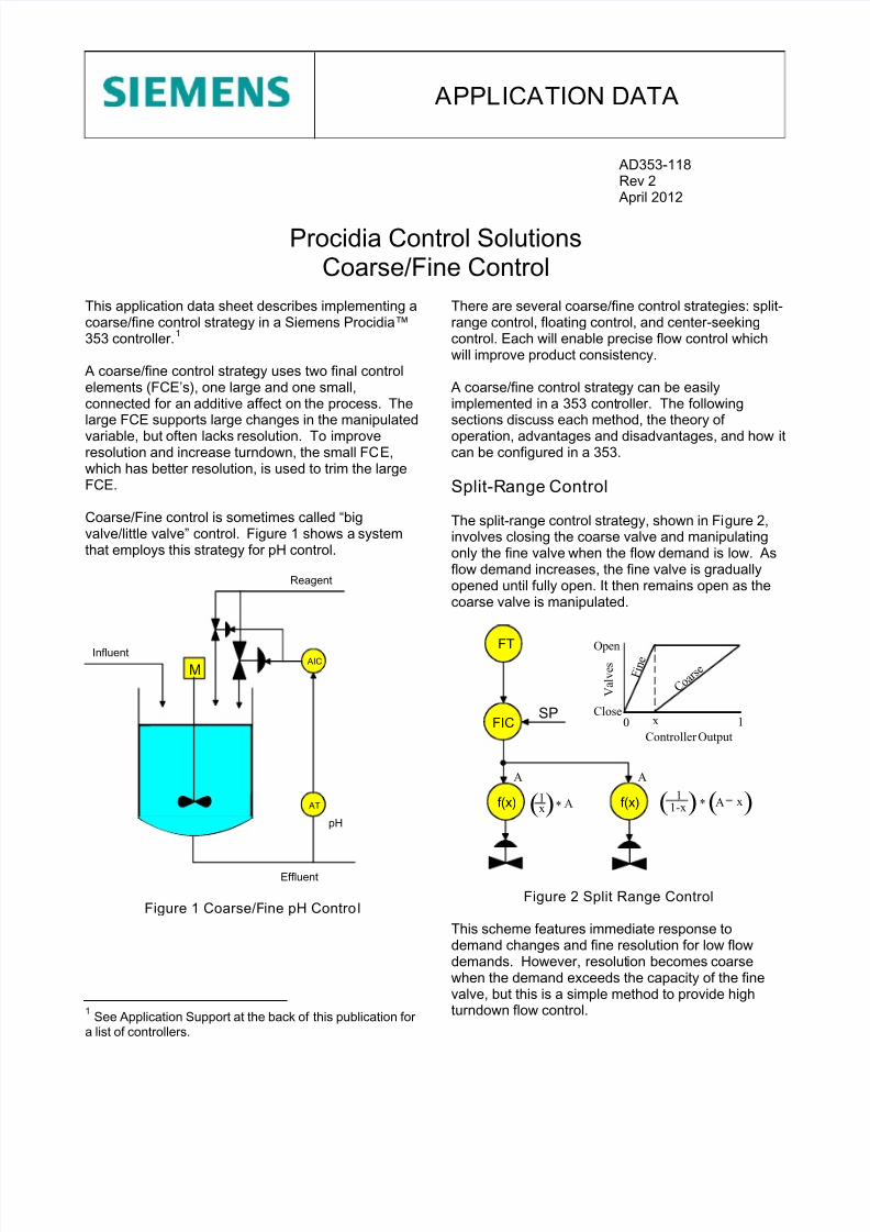
Coarse/Fine control is sometimes called “bigvalve/little valve” control. Figure 1 shows a systemthat employs this strategy for pH control.
AIC
AT
pH
Effluent
M
Reagent
Influent
Figure 1 Coarse/Fine pH Control
1 See Application Support at the back of this publication for a list of controllers.
There are several coarse/fine control strategies: split-range control, floating control, and center-seekingcontrol. Each will enable precise flow control whichwill improve product consistency.
A coarse/fine control strategy can be easilyimplemented in a 353 controller. The followingsections discuss each method, the theory of
operation, advantages and disadvantages, and how itcan be configured in a 353.
Split-Range Control
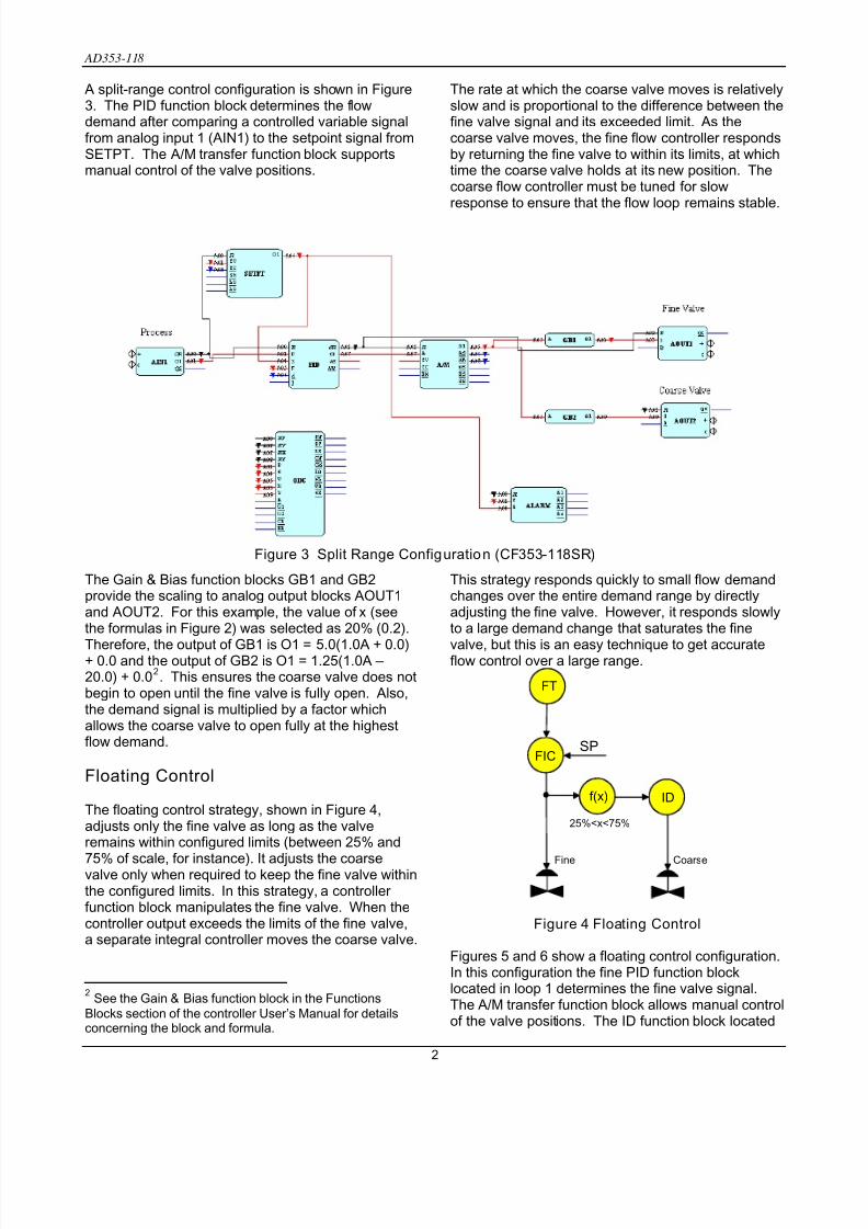
The split-range control strategy, shown in Figure 2,involves closing the coarse valve and manipulatingonly the fine valve when the flow demand is low. Asflow demand increases, the fine valve is graduallyopened until fully open. It then remains open as thecoarse valve is manipulated.
FIC
f(x)
SP
f(x)
Open
Close
V a l v e s
x
C o a r s e F
i n e
Controller Output
1x
A
A*1
1-xx( ) ( ) A( )*
A
FT
0 1
Figure 2 Split Range Control
This scheme features immediate response todemand changes and fine resolution for low flowdemands. However, resolution becomes coarsewhen the demand exceeds the capacity of the finevalve, but this is a simple method to provide highturndown flow control.
7/27/2019 AD353-118r2
http://slidepdf.com/reader/full/ad353-118r2 2/5
AD353-118
A split-range control configuration is shown in Figure3. The PID function block determines the flowdemand after comparing a controlled variable signalfrom analog input 1 (AIN1) to the setpoint signal fromSETPT. The A/M transfer function block supportsmanual control of the valve positions.
The Gain & Bias function blocks GB1 and GB2provide the scaling to analog output blocks AOUT1and AOUT2. For this example, the value of x (seethe formulas in Figure 2) was selected as 20% (0.2).
Therefore, the output of GB1 is O1 = 5.0(1.0A + 0.0)+ 0.0 and the output of GB2 is O1 = 1.25(1.0A – 20.0) + 0.02. This ensures the coarse valve does notbegin to open until the fine valve is fully open. Also,the demand signal is multiplied by a factor whichallows the coarse valve to open fully at the highestflow demand.
Floating Control
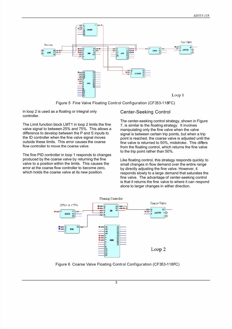
The floating control strategy, shown in Figure 4,adjusts only the fine valve as long as the valveremains within configured limits (between 25% and
75% of scale, for instance). It adjusts the coarsevalve only when required to keep the fine valve withinthe configured limits. In this strategy, a controller function block manipulates the fine valve. When thecontroller output exceeds the limits of the fine valve,a separate integral controller moves the coarse valve.
2 See the Gain & Bias function block in the FunctionsBlocks section of the controller User’s Manual for detailsconcerning the block and formula.
The rate at which the coarse valve moves is relativelyslow and is proportional to the difference between thefine valve signal and its exceeded limit. As thecoarse valve moves, the fine flow controller respondsby returning the fine valve to within its limits, at whichtime the coarse valve holds at its new position. Thecoarse flow controller must be tuned for slowresponse to ensure that the flow loop remains stable.
This strategy responds quickly to small flow demandchanges over the entire demand range by directlyadjusting the fine valve. However, it responds slowlyto a large demand change that saturates the fine
valve, but this is an easy technique to get accurateflow control over a large range.
Figure 3 Split Range Configuration (CF353-118SR)
FICSP
25%<x<75%
FT
ID
Fine Coarse
f(x)
Figure 4 Floating Control
Figures 5 and 6 show a floating control configuration.In this configuration the fine PID function blocklocated in loop 1 determines the fine valve signal.The A/M transfer function block allows manual controlof the valve positions. The ID function block located
2
7/27/2019 AD353-118r2
http://slidepdf.com/reader/full/ad353-118r2 3/5
AD353-118
in loop 2 is used as a floating or integral only
controller.
The Limit function block LMT1 in loop 2 limits the finevalve signal to between 25% and 75%. This allows adifference to develop between the P and S inputs tothe ID controller when the fine valve signal movesoutside these limits. This error causes the coarseflow controller to move the coarse valve.
The fine PID controller in loop 1 responds to changesproduced by the coarse valve by returning the finevalve to a position within the limits. This causes theerror at the coarse flow controller to become zero,
which holds the coarse valve at its new position.
Center-Seeking Control
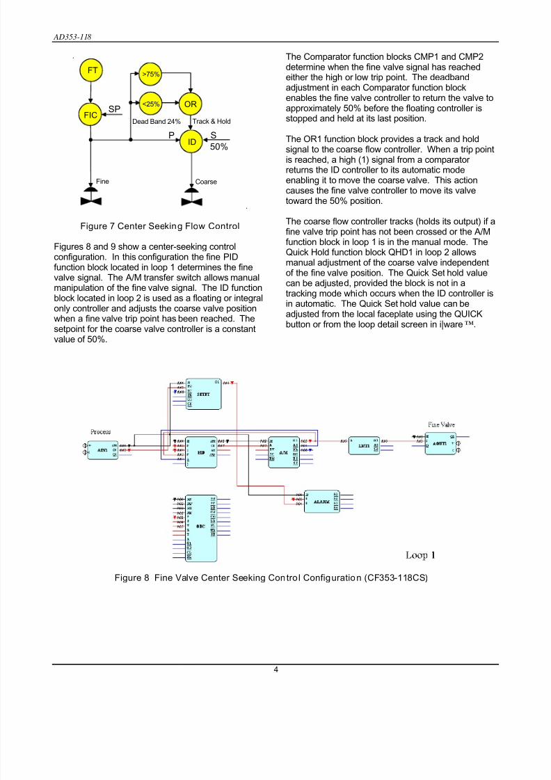
The center-seeking control strategy, shown in Figure7, is similar to the floating strategy. It involvesmanipulating only the fine valve when the valvesignal is between certain trip points, but when a trippoint is reached, the coarse valve is adjusted until thefine valve is returned to 5
0%, midstroke. This differsom the floating control, which returns the fine valve
g controlis that it returns the fine valve to where it can respondalone to larger changes in either direction.
fr to the trip point rather than 50%.
Like floating control, this strategy responds quickly tosmall changes in flow demand over the entire rangeby directly adjusting the fine valve. However, it
responds slowly to a large demand that saturates thefine valve. The advantage of center-seekin
Figure 5 Fine Valve Floating Control Configuration (CF353-118FC)
Figure 6 Coarse Valve Floating Control Conf iguration (CF353-118FC)
3
7/27/2019 AD353-118r2
http://slidepdf.com/reader/full/ad353-118r2 4/5
AD353-118
.
FICSP
FT
ID
Fine Coarse
50%P S
>75%
<25% OR
Track & HoldDead Band 24%
.
w Control
Figures 8 and 9 show a center-seeking controlconfiguration. In this configuration the fine PIDfunction block located in loop 1 determines the finevalve signal. The A/M transfer switch allows manualmanipulation of the fine valve signal. The ID functionblock located in loop 2 is used as a floating or integralonly controller and adjusts the coarse valve positionwhen a fine valve trip point has been reached. Thesetpoint for the coarse valve controller is a constantvalue of 50%.
he Comparator function blocks CMP1 and CMP2determine when the fine valve signal has reachedeither the high or low trip point. The deadbandadjustment in each Comparator function blockenables the fine valve controller to return the valve toapproximately 50% before the floating controller isstopped and held at its last position.
The OR1 function block provides a track and holdsignal to the coarse flow controller. When a trip pointis reached, a high (1) signal from a comparator returns the ID controller to its automatic modeenabling it to move the coarse valve. This actioncauses the fine valve controller to move its valvetoward the 50% position.
The coarse flow controller tracks (holds its output) if afine valve trip point has not been crossed or the A/Mfunction block in loop 1 is in the manual mode. TheQuick Hold function block QHD1 in loop 2 allowsmanual adjustment of the coarse valve independent
of the fine valve position. The Quick Set hold valuecan be adjustetracking mode whiin automatic. The Quick Set hold value can beadjusted from the local faceplate using the QUICKbutton or from the loop detail screen in i|ware™.
T
Figure 7 Center Seeking Flo
d, provided the block is not in ach occurs when the ID controller is
Figure 8 Fine Valve Center Seeking Control Configuration (CF353-118CS)
4

7/27/2019 AD353-118r2
http://slidepdf.com/reader/full/ad353-118r2 5/5
AD353-118
Appl ications
In addition to the pH control system shown in Figure
1, a coarse/fine control strategy can be implementedon many process requiring precise flow control. Oneof the above strategies can be implemented basedon the characteristics of the flow such as frequencyof changes in flow demand and the range of thesechanges.
pplication Support
User manuals for controllers and transmitters,addresses of Siemens sales representatives, andmore application data sheets can be found atwww.usa.siemens.com/ia
A
. To reach the processcontroller page, click Process Instrumentation andthen Process Controllers and Recorders. To selectthe type of assistance desired, click Support (in the
right-hand column). See AD353-138 for a list of Application Data sheets.
The configurations shown in this publication werecreated in Siemens i|config™ GraphicalConfiguration Utility. Those with CF353 inparenthesis in the figure title are available using theabove navigation, then click Software Downloads >Coarse Fine Contro l (Reference AD353-118).
The configuration(s) can be created and run in a:• Model 353 Process Automation Controller • Model 353R Rack Mount Process Automation
Controller*• i|pac™ Internet Control System*• Model 352Plus™ Single-Loop Digital Controller*
* Discontinued model
Procidia, i|ware, i|config, and 352Plus are trademarks of Siemens Industry, Inc. Other trademarks are the property of their respectiveowners. All product designations may be trademarks or product names of Siemens Industry, Inc. or other supplier companies whose use bythird parties for their own purposes could violate the rights of the owners.
Siemens Industry, Inc. assumes no liability for errors or omissions in this document or for the application and use of information in thisdocument. The information herein is subject to change without notice.
Siemens Industry, Inc. is not responsible for changes to product functionality after the publication of this document. Customers are urged toconsult with a Siemens Industry, Inc. sales representative to confirm the applicability of the information in this document to the product theypurchased.
Control circuits are provided only to assist customers in developing individual applications. Before implementing any control circuit, it shouldbe thoroughly tested under all process conditions.
Copyright © 2012, Siemens Industry, Inc.
Figure 9 Coarse Valve Center Seeking Control Configuration (CF353-118CS)
5


