AD-B157 460L P-3 AERIAL REFUELING FEASIBILITY …
32
AD-B157 460L P-3 AERIAL REFUELING FEASIBILITY EVALUATION(U) NAVAL i/i AIR TEST CENTER PATUXENT RIVER MO H C UVKOFF ET AL 24 JUL 91 NATC-FU-18R-91 XN-NAVAIR UNCLASSIFIED USGO
Transcript of AD-B157 460L P-3 AERIAL REFUELING FEASIBILITY …
AD-B157 460L P-3 AERIAL REFUELING FEASIBILITY EVALUATION(U) NAVAL i/i AIR TEST CENTER PATUXENT RIVER MO H C UVKOFF ET AL 24 JUL 91 NATC-FU-18R-91 XN-NAVAIR
UNCLASSIFIED USGO

1.0
I.I
•Jl» «. iiu
: us
L25 i 1.4
25
1.8
1.6
MICROCOPY RESOLUTION TEST CHART NATIONAL BUREAU OF STANDARDS
STANDARD REFERENCE MATERIAL 1010a (ANSI and ISO TEST CHART No. 2)
COPY NO. JÜ£
NAVAL ARTEST CENTER
REPORT NO: FW-18R-91
UNCLASSIFIED
TECHNICAL REPORT
-3 AERUL REFUELING FEASIBILITY EVALU ATION by
LT H. C. Wykoff, USN Mr. D. J. Ludwig
24 July 1991
FINAL REPORT
•1 8 26 065
DEPARTMENT OF THE NAVY NAVAL AIR TEST CENTER
PATUXENT RIVER, MARYLAND 20670-5304
A511-5114/053-D/OW19260001 NATC-6028 FW-18R-91 24 July 1991
This Technical Report presents results of an evaluation to determine the feasibility of in-flight refueling a ?-3 airplane from an S-3 tanker. The evaluation was conducted for NAVAIRSYSCOM under AIRTASK A511-5114/053-D/0W19260001, Work Unit NATC-6028.
This report completes the requirements of the AIRTASK/Work Unit.
APPROVED FOR RELEASE:
JU2-P^ J. DAKEEN By direction of the Commander, Naval Air Test Center

REPORT DOCUMENTATION PAGE Form Approved
OMB No. 07040188
Public reporting burden tor this collection of information is estimated to average I hour per response, including the time for reviewing instructions, searching existing data sources. gathering and maintaining the data needed, and completing and reviewing the collection of information Send comments regarding this burden estimate or any other aspect of this collection of information, including suggestions for reducing this burden to Washington Headquarters Services. Directorate tor information Operations and Reports. 121S Jefferson Davis Highway. Suite 1204. Arlington. VA 22202-430?. and to the Office of Management and Budget. Paperwork Reduction Project (0704-0188). Washington. DC 20503
1. AGENCY USE ONLY (Leave blank) 2. REPORT DATE
24 JULY 1991 3. REPORT TYPE AND DATES COVERED
FINAL 6-12 DECEMBER 1990 4. TITLE AND SUBTITLE
P-3 AERIAL REFUELING FEASIBILITY EVALUATION
6. AUTHOR(S)
LT H. C. WYKOFF, USN MR. D. J. LUDWIG
5. FUNDING NUMBERS
A511-5114/053-D/ 0W19260001 NATC-6028
7. PERFORMING ORGANIZATION NAME(S) AND ADDRESS(ES)
NAVAL AIR TEST CENTER DEPARTMENT OF THE NAVY PATUXENT RIVER, MARYLAND 20670-5304
PERFORMING ORGANIZATION REPORT NUMBER
FW-18R-91
9. SPONSORING/MONITORING AGENCY NAME(S) AND ADDRESS(ES)
NAVAL AIR SYSTEMS COMMAND DEPARTMENT OF THE NAVY WASHINGTON, D.C. 20361-5110
10. SPONSORING/MONITORING AGENCY REPORT NUMBER
11. SUPPLEMENTARY NOTES
12a. DISTRIBUTION/AVAILABILITY STATEMENT
DISTRIBUTION AUTHORIZED TO U.S. GOVERNMENT AGENCIES ONLY; TEST AND EVALUATION; JULY 1991. OTHER REQUESTS SHALL BE REFERRED TO COMMANDER, NAVAL AIR TEST CENTER, PATUXENT RIVER, MARYLAND 20670-5304.
12b. DISTRIBUTION CODE
13. ABSTRACT (Maximum 200 words) Aerial refueling (AR) has long been a mainstay in carrier battle group (CVBG) operations. AR from carrier-based tanker assets could significantly increase the support provided to the CVBG by maritime patrol aircraft. Previous tests have documented the flying qualities and suitability of the P-3 as a receiver behind the KC-135, KC-130, and A-7C with an AR store. Those tests documented high pilot workload during simulated AR and slow deceleration of the P-3 following aborted engagements. With the increased use of S-3 aircraft as carrier-based tankers, NAVAIRSYSCOM tasked NAVAIRTESTCEN to evaluate the handling qualities of P-3 aircraft in simulated AR positions behind the S-3 tanker and closure rate control of the P-3 receiver. Additionally, NAVAIRTESTCEN was requested to provide recommendations concerning optimum probe location and fuel system integration. Tests were conducted at NAVAIRTESTCEN during three flights from 6 to 12 December 1990, and consisted of P-3 level flight accelerations/decelerations and receiver proximity tests behind an S-3 equipped with an AR store. All testing was conducted with the AR hose/drogue retracted. Within the scope of these tests, the P-3 airplane has excellent potential to be a probe/drogue type AR receiver behind the S-3 AR store-equipped tanker. In general, the deceleration capability of the P-3C using closure rates of 3 kt or less was satisfactory for the AR mission. Additionally, tanker aerodynamic effects on the P-3 receiver, as well as receiver flying qualities at the approach (20 ft aft of the simulated drogue), precontact (5 ft aft of the drogue), and contact and inner limit positions (9 ft aft of the tanker fuselage) were satisfactory for the AR mission. The fuselage-mounted probe location on top of the flightcrew station was evaluated and should be satisfactory for the AR mission. The favored position was over the pilot's station. The wingtip- mounted probe location was unsatisfactory for the AR mission. Recommend that further proximity tests be conducted with the AR hose extended to determine where P-3 bow wave effects begin to influence the drogue as a means to determine required probe length. Recommend that further tests also be conducted with a dummy probe to verify that no objectionable aerodynamic effects are present and to establish approach procedures and AR techniques to minimize the risk of a drogue and propellor collision.
14. SUBJECT TERMS P-3 AERIAL REFUELING S-3 AERIAL REFUELING
AERIAL REFUELING 15. NUMBER OF PAGES
29
16. PRICE CODE
17. SECURITY CLASSIFICATION OF REPORT
UNCLASSIFIED
18. SECURITY CLASSIFICATION OF THIS PAGE
UNCLASSIFIED
19. SECURITY CLASSIFICATION OF ABSTRACT
UNCLASSIFIED
20. LIMITATION OF ABSTRACT
SAR NSN 754001-280-5500 Standard Form 298 (Rev 2-89)
Prescribe« by ANSI Std 2)9-18
FW-18R-91
SUMMARY
Aerial refueling (AR) has long been a mainstay in carrier battle group (CVBG) operations. AR from carrier-based tanker assets could significantly increase the support provided to the CVBG by maritime patrol aircraft. Previous tests have documented the flying qualities and suitability of the P-3 as a receiver behind the KC-135, KC-130, and A-7C with an AR store. Those tests documented high pilot workload during simulated AR and slow deceleration of the P-3 following aborted engagements. With the increased use of S-3 aircraft as carrier-based tankers, NAVAIRSYSCOM tasked NAVAIRTESTCEN to evaluate the handling qualities of P-3 aircraft in simulated AR positions behind the S-3 tanker and closure rate control of the P-3 receiver. Additionally, NAVAIRTESTCEN was requested to provide recommendations concerning optimum probe location and fuel system integration. Tests were conducted at NAVAIRTESTCEN during three flights from 6 to 12 December 1990, and consisted of P-3 level flight accelerations/decelerations and receiver proximity tests behind an S-3 equipped with an AR store. All testing was conducted with the AR hose/drogue retracted. Within the scope of these tests, the P-3 airplane has excellent potential to be a probe/drogue type AR receiver behind the S-3 AR store-equipped tanker. In general, the deceleration capability of the P-3C using closure rates of 3 kt or less was satisfactory for the AR mission. Additionally, tanker aerodynamic effects on the P-3 receiver, as well as receiver flying qualities at the approach (20 ft aft of the simulated drogue), precontact (5 ft aft of the drogue), and contact and inner limit positions (9 ft aft of the tanker fuselage) were satisfactory for the AR mission. The fuselage-mounted probe location on top of the flightcrew station was evaluated and should be satisfactory for the AR mission. The favored position was over the pilot's station. The wingtip- mounted probe location was unsatisfactory for the AR mission. Recommend that further proximity tests be conducted with the AR hose extended to determine where P-3 bow wave effects begin to influence the drogue as a means to determine required probe length. Recommend that further tests also be conducted with a dummy probe to verify that no objectionable aerodynamic effects are present and to establish approach procedures and AR techniques to minimize the risk of a drogue and propellor collision.
Accession For
HTIS GRAftI DTIC TAS Unajinounced • Just if icat ion
By Distribution/
g/
Availability Codos
Dlat
»
<3 Avail and/or
Speolal
FW-18R-91
TABLE OF CONTENTS
Page No-
INTRODUCTION BACKGROUND PURPOSE DESCRIPTION OF AIRCRAFT SCOPE OF TESTS METHOD OF TESTS 3
CLOSURE RATE CONTROL TESTS 3 PROXIMITY TESTS 4
RESULTS AND DISCUSSION 5 CLOSURE RATE CONTROL 5
GENERAL 5 SPECIFIC 5
PROXIMITY TESTS 7 GENERAL 7 TANKER AERODYNAMIC EFFECTS 7 SIMULATED PROBE LOCATION 7
Fuselage-Mounted 7 Wingtip-Mounted 8
RECEIVER AIRCRAFT FLYING QUALITIES 8 Longitudinal 8 Lateral 8 Directional 8
TANKER REFERENCES 9 CLOSURE CONTROL FOR PROXIMITY MANEUVERING 9
EMERGENCY BREAKAWAYS 9 PROBE LENGTH RECOMMENDATION 9 PROBE INSTALLATION SUGGESTIONS 10 PROPELLOR ARC CLEARANCE 10 FUEL SYSTEM INTEGRATION 10
GENERAL 10 LOCKHEED-PROPOSED FUEL SYSTEM INTEGRATION 11 ALTERNATE FUEL SYSTEM INTEGRATION 11 FUELING AND TRANSFER VALVE 11 VENT SYSTEM 12
CONCLUSIONS 13 GENERAL 13 SPECIFIC 13
RECOMMENDATIONS 15 GENERAL 15 SPECIFIC 15
REFERENCES 17
APPENDICES A. COOPER-HARPER HANDLING QUALITIES RATING SCALE 19 B. P-3 APPROACHING AT THE SIMULATED INNER LIMIT 21
POSITION
DISTRIBUTION 23
ii
FW-18R-91
INTRODUCTION
BACKGROUND
1. Aerial refueling (AR) has long been a mainstay in carrier battle group (CVBG) operations. AR from carrier-based tanker assets could significantly increase the support provided by maritime patrol aircraft to the CVBG. Previous tests have documented the flying qualities and suitability of the P-3 as a receiver behind the KC-135, KC-130, and A-7C with an AR store, as reported in reference 1. Those tests documented high pilot workload during simulated AR and slow deceleration of the P-3 following aborted engagements. Previous studies included the reference 2, Lockheed California Company (LCC) P-3 In-flight Refueling Design Report, the reference 3 Naval Postgraduate School Thesis, "Selected Human Factors Considerations for the In-flight Refueled P-3 Upgrade", and the reference 4 Naval War College Paper, "Maritime Patrol Aircraft In-flight Refueling -- Another Look". With the increased use of the S-3 as a carrier-based tanker, NAVAIRSYSCOM tasked NAVAIRTESTCEN via reference 5 to evaluate the handling qualities of P-3 aircraft in simulated AR positions behind the S-3 tanker and closure rate control of the P-3 receiver. Additionally, NAVAIRTESTCEN was requested to provide recommendations concerning optimum probe location and fuel system integration.
PURPOSE
2. The purpose of these tests was to determine the flying qualities of the P-3 in simulated AR positions behind the S-3 tanker, determine the actual deceleration capability of the P-3 as it pertained to closure rate control, and select an optimum probe location based on field of view (FOV) and airframe constraints.
DESCRIPTION OF AIRCRAFT
3. The P-3 Orion is a four-engine, low-wing, land-based airplane designed for ASW and maritime patrol. The airplane is in the 127,500 to 135,000 lb gross weight class and is powered by four Allison T56 series engines. Each engine drives a four-bladed Hamilton Standard reversible, constant-speed propeller. A detailed description of the airplane can be found in the P-3 NATOPS Flight Manual (NFM), reference 6. The test airplane, BuNo 160290, was representative of production models for the purposes of these tests.
4. The S-3 Viking is a two-engine, high-wing, carrier-based airplane designed for ASW. It is in the 35,000 to 50,000 lb gross weight class and is powered by two General Electric TF34 series high bypass turbofan engines. The S-3 was given AR tanker capability by the Airframe Change (AFC) 220 Buddy Store Tanker modification. A detailed description can be found in the S-3 NFM, reference 7. The test airplane, BuNo 159391, was representative of production models with AFC 220 for the purposes of these tests.
SCOPE OF TESTS
5. The tests were conducted during three flights totaling six P-3 flight-hours from 6 to 12 December 1990 in daylight, visual meteorological conditions. One flight consisted of level flight accelerations/decelerations (accels/decels), and two flights consisted of P-3 receiver proximity tests behind an S-3 configured with an AR store. The S-3 tanker refueling hose remained stowed during

FW-18R-91
all proximity tests. Airspeeds ranged from 200 to 281 KIAS for closure rate control tests and from 200 to 275 KIAS for proximity tests. All tests were conducted at 15,000 ft Hp. Test airplane configurations are presented in table I.
Table I
TEST AIRPLANE CONFIGURATIONS
Aircraft Configuration Landing Gear Flaps Power/Thrust
P-3C Cruise (CR) Up Up PLF(1)(2)
Maneuver (MAN) Up lOdeg PLFÜ)(2)
S-3A CR Up Up TLF<3)
NOTES: (I) Power for level flight. (2) Balanced ESHP for proximity tests; balanced and reduced outboard ESHP for closure
rate control tests. (3) Thrust for level flight.
P-3 g ->ss weight varied from 92,544 to 82,500 lb. CG varied from 25.2 to 23.0% MAC. Closure rate control test airspeeds and power settings were as listed in table II.
Table II
CLOSURE RATE CONTROL TEST CONDITIONS
Vstab(1)
(KIAS) Airplane
Configuration OAT
(°C)
Indicated ESHP Power
Configuration^2) (%)
Engine No. 1 2 3 4
200
198 202
MAN -2 1,650 1,200
800 400 400
1,650 2,200 2,600 3,000 3,400
1,650 2,200 2,600 3,000 3,400
1,650 1,200
800 400 200
100 75 50 25
Fl(3)
225 MAN 0 2,100 1,500 1,000
2,100 2,600 3,100
2,100 2,600 3,100
2,100 1,500 1,000
100 75 50
253 250
CR 0 2,050 1,700 1,150
2,300 2,700 3,300
2,300 2,700 3,300
2,300 1,700 1,150
100 75 50
275 CR 0 2,700 2,000
2,700 3,400
2,700 3,400
2,700 2,000
100 75
NOTES: (1) Stabilized airspeed prior to application of power for acceleration. (2) Power configuration - outboard ESHP setting; percentage of ESHP obtained with
balanced power at Vstab- (3) Flight idle (FI).

FW-18R-91
6. The S-3 tanker carried a standard tanker loading, consisting of an AR store on wing station (WS) W5 and an AERO-ID 300-gal drop tank on WS W6. Aerodynamic interactions and aircraft handling qualities were qualitatively evaluated. Aircraft handling qualities ratings (HQR's) were assigned in accordance with the reference 8, Cooper-Harper Handling Qualities Rating Scale shown in appendix A. A criteria for acceptable closure rate arrestment was established to provide a standard that could be used to evaluate the decel data. This criteria was based on the common refueling range of the D-704, 31-300, and A/A42R-1 AR stores, which extends from 5 to 25 ft of hose retraction upon engagement. It was considered adequate if the P-3 could be decelerated after engagement to the middle of the refueling range of the AR store. This equated to the P-3 advancing 15 ft in relation to a hypothetical tanker following reduction in ESHP. In the event of a missed engagement, the 15-ft coast would allow 9 ft of longitudinal (fore and aft) distance between the AR drogue and the plane of the propellor arc, assuming that the AR probe tip is located even with the nose of the P-3.
METHOD OF TESTS
CLOSURE RATE CONTROL TESTS
7. In the following description of the closure rate control test technique, reference is made to two airspeeds that are defined as follows:
Vstab - the stabilized airspeed at commencement of the test run, and is the simulated tanking airspeed.
Vtarget - an airspeed higher than Vstab used to establish a closure rate on the simulated drogue. For these tests, Vtarget was selected as 6 kt above Vstabi since it was the maximum hose reel takeup rate of the AR stores.
The closure rate control tests were conducted at various simulated tanking airspeeds (Vstab) using an initial balanced power setting and initial unbalanced power settings. These power settings are shown in table II. The unbalanced power settings were tested to determine if deceleration capability could be increased by using reduced outboard engine power settings. In the balanced power setting technique, the pilot established Vstab with all four engines ESHP-balanced. He then increased the power on all engines by 1,000 ESHP to accelerate the airplane to Vtarget- Upon reaching Vtargeti the four power levers were rapidly retarded to the FI stop. In the unbalanced power setting technique, the pilot established Vstab with the ESHP on the outboard engines (Nos. 1 and 4) reduced to approximately 75, 50, or 25% of the balanced ESHP setting, or to FI. The ESHP on the inboard engines (Nos. 2 and 3) was set as required to achieve Vstab- Then the ESHP on the inboard engines was increased 1,000 ESHP (or to 1,077°C TIT, whichever occurred first) to accelerate the airplane to Vtarget- Upon reaching Vtargett the inboard engine power levers were rapidly retarded to the FI stop, while the outboard engines remained at the stabilized power setting.
8. Instrumentation consisted of a sensitive airspeed indicator mounted in place of the production indicator on the pilot's console; production engine instruments for OAT, ESHP, and TIT readings; a hand-held video camcorder; and a Panasonic VHS VCR. The camcorder was used to record stabilized ESHP readings and the accels/decels from the sensitive airspeed indicator. A tape drive speed calibration was performed to determine the combined accuracy of the camcorder and playback VCR. The drive speed error was less than 0.04%. Because rates of airspeed change were to be extracted from the videotaped airspeed indicator, confidence in the response of the indicator was established by comparing the maximum decel recorded during the test with data collected at NAVAIRTESTCEN with an instrumented P-3 in May 1981 (data documented in the reference 9 technical report). The minimum time recorded to decel 6 kt during this test was 6.5 sec. At similar flight conditions, the time required for the instrumented P-3 to decel 6 kt, as read from strip charts, was 7.0 sec. This result provided sufficient confidence in the response rate of the pitot-static airspeed indicator for the purposes of these tests.
FW-18R-91
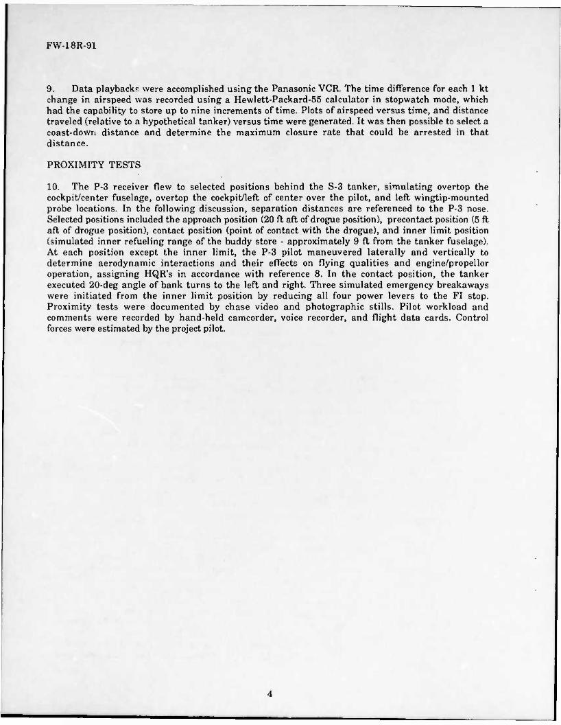
9. Data playback? were accomplished using the Panasonic VCR. The time difference for each 1 kt change in airspeed was recorded using a Hewlett-Packard-55 calculator in stopwatch mode, which had the capability to store up to nine increments of time. Plots of airspeed versus time, and distance traveled (relative to a hypothetical tanker) versus time were generated. It was then possible to select a coast-down distance and determine the maximum closure rate that could be arrested in that distance.
PROXIMITY TESTS
10. The P-3 receiver flew to selected positions behind the S-3 tanker, simulating overtop the cockpit/center fuselage, overtop the cockpit/left of center over the pilot, and left wingtip-mounted probe locations. In the following discussion, separation distances are referenced to the P-3 nose. Selected positions included the approach position (20 ft aft of drogue position), precontact position (5 ft aft of drogue position), contact position (point of contact with the drogue), and inner limit position (simulated inner refueling range of the buddy store - approximately 9 ft from the tanker fuselage). At each position except the inner limit, the P-3 pilot maneuvered laterally and vertically to determine aerodynamic interactions and their effects on flying qualities and engine/propellor operation, assigning HQR's in accordance with reference 8. In the contact position, the tanker executed 20-deg angle of bank turns to the left and right. Three simulated emergency breakaways were initiated from the inner limit position by reducing all four power levers to the FI stop. Proximity tests were documented by chase video and photographic stills. Pilot workload and comments were recorded by hand-held camcorder, voice recorder, and flight data cards. Control forces were estimated by the project pilot.

FW-18R-91
RESULTS AND DISCUSSION
CLOSURE RATE CONTROL
GENERAL
11. The deceleration capability of the P-3C was evaluated to determine adequacy for arresting closure to the AR drogue using the test conditions shown in table II. The simulated closure rate of 6 kt (10 ft/sec) could not be arrested within the established maximum coast distance of 15 ft (see paragraph 6). The best deceleration occurred from 281 to 275 KIAS, using a four-engine snap decel to FI where the coast distance was 23 ft in relation to a tanker flying at 275 KIAS. By analyzing the deceleration data, it was determined that at 275 KIAS, a 4.0 kt closure rate was the maximum that could be arrested in 15 ft. Deceleration analysis showed the other tested airspeeds to be worse in terms of deceleration rate. At all airspeeds tested, 3 kt was an acceptable closure rate that could be arresteü within the established 15 ft maximum coast distance. Current Navy receiver NFM's recommend using closure rates of 3 to 5 kt regardless of airspeed. P-3 pilots will be able to use closure rates up to 3 kt over the full refueling airspeed envelope without pushing too far into the refueling range, providing ±10 ft of fore and aft maneuvering distance while remaining within the refueling range. In the event of a missed engagement, up to 3 kt of closure rate will be arrested with adequate drogue/propellor separation (9 ft). Within the scope of these tests, the deceleration capability of the P-3 using closure rates up to 3 kt is satisfactory for the AR mission.
SPECIFIC
12. Various outboard reduced power settings were evaluated to determine their effect on closure rate arrestment capability. Maximum closure rates that could be arrested in 15 ft relative to the tanker for various power settings are presented in table III.

FW-18R-91
Table III
MAXIMUM CLOSURE RATES FOR VARIOUS AIRSPEEDS AND POWER SETTINGS
Simulated Tanking Airspeed (KIAS)
Power Configuration'*'
(%)
Maximum Closure Rate<2)
(kt) Comments
200 100 3.2 Good maximum closure rate. 75 2.2 Low maximum closure rate. 50 1.5 Maximum closure rate too low.
Inboard ESHP limited by TIT. 25 2.5 Low maximum closure rate.
Inboard ESHP limited by TIT. FI 3.0 Good maximum closure rate.
Inboard ESHP limited by TIT. 225 100 2.7 Low maximum closure rate.
75 3.0 Good maximum closure rate. 50 3.5 Good maximum closure rate.
Inboard ESHP limited by TIT. 250 100 2.5 Low maximum closure rate.
75 3.5 Good maximum closure rate. 50 3.0 Good maximum closure rate.
Inboard ESHP limited by TIT. 275 100 4.0 Good maximum closure rate.
75 3.5 Good maximum closure rate. Inboard ESHP limited by TIT.
NOTES: (1) Refer to table II for definitions of power settings. (2) Closure rate is the relative speed between the receiver and refueling drog\.a at the
point of drogue engagement. Maximum closure rate is the maximum relative speed, at drogue engagement, that can be reduced to 0 kt at 15 ft beyond the plane of the free- trailing drogue as viewed from the receiver.
The data did not show conclusively that any one power configuration provided better closure rate control than others. Generally, outboard engine power settings less than 75% of the power set for Vstab resulted in inboard power being limited by TIT. At 200 and 275 KIAS, the best closure control was obtained by using all four power levers. At 225 and 250 KIAS, the reduced outboard engine horsepower settings provided better closure control. However, at the 50% settings, the pilot was reaching the TIT limit on the inboard engines. At 275 KIAS, either using all four power levers or the inboard power levers with 75% outboard engine power provided good closure control. The 75% power setting, however, resulted in reaching the TIT limit on the inboard engines. For closure rate control, either the 100 or 75% power settings will be adequate for the AR mission. At the optimum airspeed for AR (250 KIAS), the 75% outboard engine power setting will allow the P-3 pilot to use up to 3.5 kt of closure rate to the drogue, providing adequate probability of probe-to-drogue latch. Within the scope of these tests, the 75 and 100% outboard engine power settings of the P-3 receiver airplane provide adequate closure rate control and are satisfactory for the AR mission.

FW-18R-91
PROXIMITY TESTS
GENERAL
13. P-3 receiver handling qualities were evaluated at simulated AR positions behind the S-3 tanker at 15,000 ft Hp at 200, 225, 250, and 275 KIAS. The 200 and 225 KIAS tests were conducted in configuration MAN (gear up, flaps at 10 deg), and the 250 and 275 KIAS tests were conducted in configuration CR (gear and flaps up). The following paragraphs refer to the tests conducted at 250 KIAS, which was qualitatively determined to yield the best receiver aircraft handling qualities. However, handling qualities at other tested airspeeds were not significantly degraded. Additionally, these data are associated with the simulated probe over the pilot. The pilot controlled airspeed and closure rate using the 75% power setting for Vst,ab (see table II), using the inboard engines for power adjustments. Because these proximity tests were conducted with the AR hose retracted, the tracking task performed by the pilot to evaluate aircraft handling qualities was an approximation. Recommend that further tests be conducted behind an S-3 tanker with the AR hose extended to provide the pilot with a real target for the tracking task associated with AR.
TANKER AERODYNAMIC EFFECTS
14. Tanker aerodynamic effects on the P-3 receiver were evaluated at simulated AR positions behind the S-3 tanker. Appendix B depicts the P-3 approaching the inner limit position. When stable in the approach position (20 ft aft of the simulated drogue), there were no noticeable aerodynamic effects on the P-3 from the tanker. As the P-3 closed on the tanker, the flow field behind the S-3 produced a slight right rolling moment that was easily correctable with approximately 3-5 lb of left aileron pressure. This rolling moment remained essentially constant throughout the approach to the inner limit position (9 ft aft of the tanker fuselage). When in or near any of the AR positions, there was neither airframe buffet or noticeable downwash effects. As the P-3 was maneuvered laterally and vertically about each AR position, the following additional aerodynamic effects were noted. When stable at a point approximately 4-5 ft above each position, a slight rudder buzz was felt through the rudder pedals, but it was not objectionable. As the P-3 was flown approximately 5 ft left of the proper position, the right rolling moment began to gradually increase. This tended to push the receiver airplane back into the proper position. The rolling moment was easily controllable within the limits of these tests. When flown to the right of the proper position, the airflow from the tanker's fuselage produced a weak left rolling moment beginning at approximately 3 ft right of the proper position. This rolling moment also tended to push the P-3 back into the proper position. No aerodynamic effects were noted when flying below the proper position. The P-3 pilot will not encounter any significant adverse effects because of tanker aerodynamic effects during the AR evolution. Within the scope of these tests, the S-3 tanker aerodynamic effects on the P-3 receiver airplane are satisfactory for the AR mission.
SIMULATED PROBE LOCATION
Fuselage-Mounted
15. The two simulated fuselage-mounted probe locations were evaluated to determine the best location for receiver pilot visibility and lineup to the simulated drogue and best location based on airframe constraints. The first simulation was located directly over the pilot in the left seat, and the second was over the engineer in the center seat. There were no discernible differences between the two locations during simulated AR, with the exception of relatively minor FOV changes. Qualitatively, locating the probe over the pilot should reduce any lateral parallax error that could lead to probe and drogue misalignment. The over-the-pilot position will allow the fuel tube to run straight aft, clearing the top Tactical Air Control and Navigation System antenna, sextant viewing port, and flight station overhead emergency exit, while the center line position would require more complex tube bends and support structure to clear the escape hatch. A probe location on the fuselage will allow the P-3 pilot to have an adequate FOV of the probe and tanker aircraft during the AR evolution. Within the scope of these tests, a fuselage-mounted probe located over the top of the

FW-18R-91
flightcrew station should be satisfactory for the P-3 AR mission. Recommend that further tests be conducted with an AR probe located over the pilot's station on top of the fuselage to verify the suitability of that location.
Wingtip-Mounted.
16. A simulated probe location on the P-3's port wingtip was briefly investigated. The wingtip position was evaluated assuming a 24-ft probe. This length was chosen to provide adequate tanker-to- receiver clearance for the purposes of these tests and to allow the pilot to see the probe tip, which would reside 90 deg to the pilot's forward line of sight. The location of the simulated probe precluded viewing the probe and tanker airplane at the same time. Additionally, the port wingtip location forced the P-3 to be flown in and around the S-3's starboard wingtip vortex, greatly increasing pilot workload. The wingtip location investigation was terminated during the initial attempt at approaching the precontact position because of the inability to maintain sight of the tanker while simulating viewing the probe, and the ever-increasing pilot workload. For the wingtip probe position, the pilot will have to continually look away from the tanker to make corrections in all three axes to achieve lineup, increasing the chance of a midair collision between tanker and receiver. The continuous aileron inputs required to remain near the correct lateral position produced large (approximately ±4 ft) vertical deviations of the port wingtip, which would preclude successful engagement of the drogue. Within the scope of these tests, the wingtip probe location is unsatisfactory for the AR mission.
RECEIVER AIRCRAFT FLYING QUALITIES
Longitudinal
17. Longitudinal flying qualities were qualitatively evaluated from a stable, trimmed approach position and while moving in to the inner limit position. Vertical position keeping was easily maintained throughout the approach to the inner limit position. Using only the inboard engines to control closure rate made trim changes because of power unnoticeable. Maintaining vertical position ±2 ft was easy, requiring only small, infrequent (every 8-10 sec) longitudinal control inputs (HQR-2). The P-3 pilot will be able to maintain precise vertical position, without fatigue, throughout the AR evolution. Within the scope of these tests, the longitudinal flying qualities of the P-3 during AR from behind an S-3 tanker are satisfactory for the AR mission.
Lateral
18. Lateral flying qualities were qualitatively evaluated from a stable, trimmed approach position and while moving in to the inner limit position. Lateral position keeping was easily maintained throughout the approach to the inner limit position. The tanker-induced right rolling moment was correctable with approximately 3-5 lb of left aileron force. The lack of lateral positive control centering necessitated a cyclic application of left control wheel input. Because of the relatively small inputs required, the forces were not considered fatiguing. The lateral force could be trimmed out; however, this required even more left and right control inputs because of the lack of centering. Maintaining lateral position within ±2 ft was relatively easy (HQR-3). The P-3 pilot will be able to maintain lateral position, without fatigue, throughout the AR evolution. Within the scope of these tests, the lateral flying qualities of the P-3 during AR from behind an S-3 tanker are satisfactory for the AR mission.
Directional
19. Directional flying qualities were qualitatively evaluated from a stable, trimmed approach position and while moving in to the inner limit position. Directional stability appeared to be unaffected by the tanker's aerodynamic influences. Small rudder inputs (less than 1/2 in.) could be used to assist in lateral position keeping and to "point" the simulated probe. As stated in paragraph 14, a slight rudder buzz was felt through the rudder pedals when the receiver aircraft was
8

FW-18R-91
flown approximately 4-5 ft high of the proper position, but it was not objectionable and could serve as a tactile cue to a "too high" position. The basic directional stability of the P-3 will allow the pilot to establish and maintain the correct position during the AR evolution. Within the scope of these tests, the directional flying qualities of the P-3 during AR from behind an S-3 tanker are satisfactory for the AR mission.
TANKER REFERENCES
20. The pilot's FOV from the P-3 cockpit was evaluated from the approach to the inner limit positions behind the S-3 tanker. The FOV from the P-3 allowed viewing the left wing, fuselage, and tail section of the tanker, up to and including the contact position when simulating a probe mounted on the fuselage. As the P-3 passed the contact position and moved toward the inner limit, the vertical tail of the tanker began to disappear past the top of the P-3 windshield. This did not diminish the available visual cues used by the pilot to maintain position. The P-3 pilot will have an adequate FOV and will be able to perceive sufficient visual cues to maintain position throughout the AR evolution. Within the scope of these tests, the P-3 pilot's FOV is satisfactory for the AR mission.
CLOSURE CONTROL FOR PROXIMITY MANEUVERING
21. Closure rate control during proximity tests was qualitatively evaluated using the 75% power setting and varying ESHP of the inboard engines to maneuver. The P-3 pilot could easily maneuver to and maintain any of the proximity test positions evaluated. To begin closure from the approach position, engine power was increased approximately two knob widths (approximately 300 SHP each) on the inboard engines to initiate a comfortable closure rate to the tanker. Qualitatively, the closure rate could be stopped immediately at any time by a reduction of power on the inboard engines to the previous setting or lower. Closure rate could be maintained within ±1 kt by small (less than one knob width), infrequent (every 4-6 sec) power lever movements (HQR-3). At no time was control of closure rate in question. Within the scope of these tests, the ease of controlling P-3 closure rate while maneuvering in proximity to the S-3 tanker is satisfactory for the AR mission.
EMERGENCY BREAKAWAYS
22. Emergency breakaways were evaluated during three breakaways at 15,000 ft Hp and 250 KIAS to determine the adequacy of separation rate of the P-3 from the S-3 tanker. Breakaways were initiated from the inner limit position (9-12 ft from the tanker fuselage) by snapping all four power levers to FI. Aircraft separation began immediately upon reduction of power. Rate of separation, 1 sec following reduction of power, was 3.1 ft/sec (averaged among the three breakaways). A separation rate of 10 ft/sec was achieved in an average time of 3.6 sec. When emergency situations dictate, P-3 pilots will be able to quickly and expeditiously separate from the tanker by pulling the four power levers to FI. Within the scope of these tests, the deceleration capability of the P-3 during AR emergency breakaways is satisfactory for the AR mission.
PROBE LENGTH RECOMMENDATION
23. The over-the-pilot probe location was studied to determine the minimum unsupported AR probe length required to allow the pilot to view the probe without slumping or otherwise altering his normal viewing position. Using the reference 2 forward support point for the retractable installation (fuselage station (FS) 261) and the pilot FOV based on the "design eye" point of view for the pilot, the AR probe unsupported length would be 10 ft. The unsupported AR probe length for a probe that extends to a point even with the P-3 nose would be 14 ft. It is necessary that the AR probe extend forward far enough to be out of the bow wave of the P-3 to reduce lifting effects on the AR drogue prior to contact. By locating the probe out of the P-3 bow wave, the pilot will be able to approach the drogue with lower closure rates and fewer last minute corrections in pitch, thereby reducing pilot workload and increasing engagement success rate. Recommend that further proximity tests be conducted with the AR hose extended to determine where P-3 bow wave effects begin to influence the drogue as a means to determine required probe length.
9

FW-18R-91
PROBE INSTALLATION SUGGESTIONS
24. Fixed- and retractable-probe installations were assessed to determine their relative merits and recommend the best method for the P-3 application. Reference 2 proposed a retractable-probe installation similar to that of the S-3, but surface-mounted rather than integral to the airframe. Reference 2 cautioned that the airflow velocity over the forward cockpit was nearly sonic and disturbances in that area may cause excessive velocities with accompanying sonic shock, which may result in excessive drag and cockpit noise levels. Reference 2 suggested, however, that proper fairing of the probe installation could prevent these unwanted effects. The effect of sonic airflow over the forward cockpit would be present with or without a retractable probe since the retractable probe would require a considerable bulge in that area and would present a potentially larger frontal area than the fixed probe because of the fairing that would enclose the retraction, mechanism. A nonretractable probe could be installed with less cost and complexity than a retractable probe. The retractable probe would require positive and negative pressure relief valves and drain lines back to the fuel tank to accommodate the volume change in the fuel tube during probe extension and retraction, while the fixed probe would not. The retractable probe would require a hand crank or other backup extension device that would add complexity to the installation. Probe replacement costs and downtime would be less with a nonretractable probe, provided the design incorporates a detachable probe mast that would unscrew from the mounting structure on the upper forward cockpit area. For flight where no AR is required or anticipated, this provision would allow the probe mast to be removed and replaced with an aerodynamic plug. In the event that the probe mast is damaged, it could be easily unscrewed and replaced by a new probe mast. Within the scope of these tests, the fixed, nonretractable probe installation is the best choice for a retrofit P-3 probe/drogue AR capability. Recommend that a trial installation of a fixed dummy probe be tested in flight to verify that no objectionable aerodynamic effects are present.
PROPELLOR ARC CLEARANCE
25. The over-the-pilot fuselage probe location was evaluated to determine the clearances that would exist between the propellor arc and drogue/hose in the event of a missed engagement and overrun of the drogue. The over-the-pilot probe location would place the probe slightly above the arc of the inboard propellors, depending upon the actual placement of the probe. In the event of a missed engagement where the pilot overruns the drogue and assuming that the drogue passes directly aft along the axis of the probe, the drogue would clear the No. 2 propellor arc with a minimum of 8 ft diagonal clearance. In the event of a missed engagement while using excessive closure rate, the P-3 pilot need only decelerate while maintaining vertical and lateral position or push over slightly to ensure that the drogue clears the propellor. Within the scope of these tests, the over-the-pilot fuselage probe location provides adequate drogue and propellor arc clearance and is satisfactory for the AR mission. Recommend that further tests be conducted with a dummy probe installation to establish approach procedures and AR techniques to minimize the risk of a drogue and propellor collision.
FUEL SYSTEM INTEGRATION
GENERAL
26. The P-3C fuel system was reviewed to identify potential methods for integrating the refueling probe into the existing fuel system and to determine its suitability for the AR mission. Because this was a preliminary study based on a review of references 1, 2, 10, and 11, recommend that a more detailed fuel system performance analysis be completed to determine fuel flow rate capability and fuel pressure surge potential.
10
FW-18R-91
LOCKHEED-PROPOSED FUEL SYSTEM INTEGRATION
27. Reference 2 recommended routing the AR fuel line from the probe to the ground pressure fueling adapter. The refueling tube would be run straight aft along the outer surface of the P-3 fuselage and enter into the cabin area at FS 755, which is approximately 2 ft aft of the port overwing emergency escape exit. The fuel tube would follow the inside contour of the cabin and pass down the starboard side through the cabin floor just aft of the sonobuoy storage rack. The fuel tube would run forward through the hydraulic service center on the starboard side, exiting into the wing fillet area aft of the pressure refueling manifold. The fuel line would then connect to a new pressure refueling manifold with three legs to accommodate the AR line. A check valve would be installed somewhere in the AR feed line to the pressure refueling manifold to prevent backflow into the AR probe during ground refueling. The P-3 pressure refueling system is designed to fill all tanks at a rate of 600 gpm at 45 psig. Maximum-recommended fueling pressure is 55 psi, which is compatible with current U.S. Navy and Air Force tanker delivery pressures specified at 50 ±5 psi. Within the scope of the review, the method for integrating the refueling probe into the P-3 fuel system proposed in the reference 2 LCC design report is satisfactory for the AR mission.
ALTERNATE FUEL SYSTEM INTEGRATION
28. Other methods of fuel system integration were investigated to determine their suitability for the AR mission. One alternative method would be to connect the AR manifold into the fuselage tanks 5 and 5A interconnect. This interconnect is currently a flexible line that would be removed and replaced with a new manifold designed to minimize head loss during fuselage tank fuel transfers and AR. The advantages over the reference 2 method would be as follows:
a. The total length of AR plumbing would be approximately 21 ft less for the alternate method, thus reducing head loss because of pipe length.
b. The alternate method would reduce the amount of cabin area plumbing, particularly eliminating the need to run the tubing from the portside to the starboard side of the cabin.
c. The alternate method would potentially reduce the number of tube bends and complexity of installation.
Recommend that a further study be conducted to determine the optimum location for tubing runs associated with the alternate fuel system integration method and develop an analytical comparison of fuel transfer rate performance between the LCC- and NAVAIRTESTCEN-proposed fuel system integration methods.
FUELING AND TRANSFER VALVE
29. The existing P-3 fuel system uses fueling and transfer valves (FTV's) to control fuel flow into each fuel tank. Two valve poppets are controlled by a float-actuated pilot valve. The FTVs in tanks Nos. 1, 2, 3, 4, 5, and 5A could be manually opened or closed at the ground refueling panel (opened only with fuel pressure applied), but only FTV's in wing tanks Nos. 1, 2, 3, and 4 could be manually operated from the cockpit. For AR, the flightcrew will need to open the tank No. 5 FTVs for refueling and close them for transfer operations from tank No. 5 to the wing tanks. Reference 2 recommended a procedure for testing the FTV's prior to AR that required the additional tank No. 5 FTV switches, an FTV shutoff test switch, and FTV shutoff indicator lights. If an FTV failed the pretest, that FTV would be manually closed for AR. The capability to pretest the FTV's in flight prior to AR will rf.duce the risk of fuel tank overpressurization because of a failed FTV. The flightcrew will be able to isolate the affected tank from fuel delivery pressure during AR, thus allowing the P-3 to refuel. Recommend that the FTV shutoff precheck test, associated switches, and indicator lights proposed in the reference 2 LCC design report be incorporated into the P-3 AR design.
11

FW-18R-91
VENT SYSTEM
30. All tanks (Nos. 1, 2, 3, 4, 5, and 5A) were vented to relieve tank pressure during ground refueling, intertank transfers and to relieve positive/negative tank pressures because of normal expansion and contraction. All tanks were equipped with vent valves to minimize spillage and prevent siphoning of fuel overboard during maneuvers. During pressure refueling on the ground, the fuel tanks must vent properly to prevent tank damage. As stated in a reference 10 warning, "If any tank receiving fuel does not vent during the initial phase of fueling operations, fueling must be stopped immediately to prevent aircraft structural damage. Blocked vents or failure of vent system during fueling can cause bladder cell or wing tank rupture and structural damage." AR will also require fully operating tank vents to prevent tank damage. Without any means for the P-3 flightcrew to monitor tank venting (done by ground personnel during pressure refueling) during AR, there is a risk of overpressurizing any of the five fuel tanks, possibly resulting in structural damage and loss of aircraft. As previously reported in reference 1, recommend that a system be included in any P-3 AR system design that will determine if positive venting is taking place in the fuel tanks during AR. Recommend that tank overpressurization indicators for each tank be provided to the flightcrew as one solution to the vent detection problem during AR. Additionally, recommend that the AR fuel system include automatic FTV closure if the tank is overpressurized.
12

FW-18R-91
CONCLUSIONS
GENERAL
31. Within the scope of these tests, the P-3 airplane has excellent potential to be a probe/drogue type aerial refueling (AR) receiver behind the S-3 AR store-equipped tanker.
SPECIFIC
32. Within the scope of these tests, the following are satisfactory for the AR mission:
a. The deceleration capability of the P-3C using closure rates up to 3 kt (paragraph 11).
b. The 75 and 100% outboard engine power settings of the P-3 receiver airplane, which provide adequate closure rate control (paragraph 12).
c. The S-3 tanker aerodynamic effects on the P-3 receiver airplane (paragraph 14).
d. The longitudinal, lateral, and directional flying qualities of the P-3 during AR from behind an S-3 tanker (paragraphs 17,18, and 19).
e. The P-3 pilot's field of view (paragraph 20).
f. The ease of controlling P-3 closure rate while maneuvering in proximity to the S-3 tanker (paragraph 21).
g. The deceleration capability of the P-3 during AR emergency breakaways (paragraph 22).
33. Within the scope of these tests, a fixed rtonretractable probe located over the pilot on the top of the fuselage is the best choice for a retrofit P-3 probe/drogue AR capability and provides adequate drogue and propellor arc clearance for the AR mission (paragraphs 15, 24, and 25).
34. Within the scope of the review, the method for integrating the refueling probe into the P-3 fuel system proposed in the Lockheed California Company design report is satisfactory for the AR mission (paragraph 27).
35. Within the scope of these tests, the wingtip probe location is unsatisfactory for the AR mission (paragraph 16).
13

FW-18R-91
THIS PAGE INTENTIONALLY LEFT BLANK
14

FW-18R-91
RECOMMENDATIONS
GENERAL
36. Recommend continuation of the AR feasibility evaluation to determine suitability of the P-3 as a receiver.
SPECIFIC
37. Conduct further tests behind an S-3 tanker with the aerial refueling (AR) hose extended to provide the pilot with a real target for the tracking task associated with AR (paragraph 13).
38. Conduct further tests with the AR probe located over the pilot's station on top of the fuselage to verify the suitability ofthat location (paragraph 15).
39. Conduct further proximity tests with the AR hose extended to determine where P-3 bow wave effects begin to influence the drogue as a means to determine required probe length (paragraph 23).
40. Test in flight a trial installation of a fixed dummy probe to verify that no objectionable aerodynamic effects are present (paragraph 24).
41. Conduct further tests with a dummy probe installation to establish approach procedures and AR techniques to minimize the risk of a drogue and propellor collision (paragraph 25).
42. Complete a more detailed fuel system performance analysis to determine fuel flow rate capability and fuel pressure surge potential (paragraph 26).
43. Conduct a further study to determine the optimum location for tubing runs associated with the alternate fuel system integration method and develop an analytical comparison of fuel transfer rate performance between the Lockheed California Company (LCC)- and NAVAIRTESTCEN-proposed fuel system integration methods (paragraph 28).
44. Incorporate the fueling and transfer valve (FTV) shutoff precheck test, associated switches, and indicator lights proposed in the LCC design report into the P-3 AR design (paragraph 29).
45. Include a system in any P-3 AR system design that will determine if positive venting is taking place in the fuel tanks during AR (paragraph 30).
46. Provide tank overpressurization indicators for each tank to the flightcrew as one solution to the vent detection problem during AR (paragraph 30).
47. Include automatic FTV closure in the AR fuel system if the tank is overpressurized (paragraph 30).
15

FW-18R-91
THIS PAGE INTENTIONALLY LEFT BLANK
16

FW-18R-91
REFERENCES
1. NAVAIRTESTCEN Technical Report AT-54R-80, Evaluation of the Feasibility of In-flight Refueling for the P-3B/C Airplane, of 29 Sep 1980.
2. Lockheed California Company Report LR 28442, P-3 In-flight Refueling Design Report, of Jan 1978.
3. Naval Postgraduate School Thesis, "Selected Human Factors Considerations for the In-flight Refueled P-3 Upgrade," of Mar 1981.
4. Naval War College Paper, "Maritime Patrol Aircraft In-flight Refueling-Another Look," of 3 Mar 1989.
5. AIRTASK A511-5114/053-D/0W19260001, Work Unit NATC-6028, of 28 Sep 1989.
6. NAVAIR 01-75PAC-1, NATOPS Flight Manual, Navy Model P-3C Aircraft, of 15 Jun 1988.
7. NAVAIR 01-S3AAA-1, NATOPS Flight Manual, Navy Model S-3A Aircraft, of 15 Sep 1987.
8. NASA Technical Note, NASA TN D-5153, The Use of Pilot Rating in the Evaluation of Aircraft Handling Qualities, of Apr 1969.
9. NAVAIRTESTCEN Technical Report AT-45R-82, Flight Fidelity Evaluation of the P-3C Operational Flight Trainer, Device 2F87(F), of 2 Mar 1983.
10. NAVAIR Technical Manual 01-75PAA-2-4.7, Aircraft Fuel System Organizational Maintenance Instructions for Navy Models P-3A, P-3B, and P-3C Aircraft, of 15 Nov 1986, with Rapid Action Change 4 of 6 Jan 1990.
11. NAVAIR Technical Manual 01-75PAA-2-1, General Information and Servicing Organizational Maintenance Instructions for Aircraft Models P-3A, P-3B, and P-3C, of 1 Nov 1984, with Change 1 of 1 Oct 1986.
17

FW-18R-91
THIS PAGE INTENTIONALLY LEFT BLANK
18

FW-18R-91
COOPER-HARPER HANDLING QUALITIES RATING SCALE
ADEQUACY FOR SELECTED TASK OR REQUIRED OPERATION*
DEFICIENCIES WARRANT
«MOVEMENT
AIRCRAFT CHARACTERISTICS
DEMANDS ON THE PHOT IN SELECTED TASK OR REQUIREO OPERATION-
PILOT RATING
EXCELLENT NNHIY OES4RASIE
PILOT COMPENSATION NOT A FACTOR FOR OESIRED PERFORMANCE
«OOO NESIISWLE DEFICIENCIES
PILOT COMPENSATION NO OESIREO PERFORMANCE
FAM-SOMEMIIOLY UNPLEASANT DEFICIENCKS
MINMML PHOT COMPf NSATWN Rf ONWEO FOR OESIREO PERFORMANCE
DEFICIENCIES OESIREO PERFORMANCE REQUIRES MO0ERATS PILOT COMPE NSATWN
MODERATELV OMCTWRAtLE DEFICIENCIES
AOEOUATE PERFORMANCE REQUIRES CONSIOERASLE PILOT COMPENSATION
VERY OUtCTNNASLI OUT TOLERASLE OEFKIENCIF!
ADEOOAn PERFORMANCE AEOUNUS EXTENSIVE PHOT COMPENSATION
PNPROVEMENT MANOATONY H •ANN OlFtCItRCIES CONTROL WILL IE LOST OORMO SOME PORTION OF
REOOMEO OPERATNM
DEFICIENCIES REONN»
NRPROVEMENT
AOEOUATE PERFORMANCE NOT ATTAMAOLE WITH •AMR DEFKIENCIES MAXSRW TDLERAHE PILOT COMPENSATION
CONTROllAllirTY NOT M auESTWN 7
MAJOR DEFICIENCIES CONSIOERASLE PILOT COMPENSATION • REOOMEO PON CONTROL 8
MAJOR OEFICKNCKS INTENSE PN.OT COMPENSATION • REQUIRES TO RETANI CONTROL 9
ED
• OEFMITION OF REOUIREO OPERATION INVOIVES OESISNATION OF FLICHT PHASE ANO/OR SUDPHASESWITH ACCOMPANVMS CONDITIONS.
19 APPENDIX A

FW-18R-91
THIS PAGE INTENTIONALLY LEFT BLANK
20

FW-18R-91
P-3 APPROACHING AT THE SIMULATED INNER LIMIT POSITION
APPENDIX B

FW-18R-91
THIS PAGE INTENTIONALLY LEFT BLANK
22

FW-18R-91
DISTRIBUTION:
NAVAIRSYSCOM (PMA240) (2) NAVAIRSYSCOM (AIR-5114B) (2) NAVAIRSYSCOM (AIR-5164L) (2) NAVAIRSYSCOM (AIR-53031E) (2) NAVAIRSYSCOM (AIR-5004) (2) DTIC (2)
23

55 CO
,c c
3 3 j sj ci i £ _ fc* .5? < < .2 2 *
0« co < 5 k3
.5 j
IS] 111 v. E •**
< < a
°? <? | Cu CO <
55
I;
JO
^ 3
H M n v
o 6
55 O
| 3 2 < "g > I w
>
u
o.
CO < w E ü
Ed 3 E Ed H 0ÄK
J° rf °" a w «« ij < < co 55
o o o to
3= o 3
E 3
CO !2 rtpOO
Cn^fg OS 3 <o
3z
a
111 0 3 4
ill
. en — co en « —; «H > 3 a
£ * CO
s —So .a g c e S ° is "3.2 E-o «5c5§ »"st
aSsS
1 I i < 3 < > Cd
a •—
1 3
•a c a
a 55
CO
co < Ed Eh
Ü 55
Ed 5 E Ed i- « a 3 S 3 w EC«
co 55
a.
8
is o a CO
_ „ O 00
rH K 2 CO _>,<» in r\ 3 •? -H pi "» » '-' > sis*?
£*1 o:5 3 •> -S s tl ^
Ill 3 C *J cr a> fi £ O a, u ^
§ Si « c « I 4) «J ~
§°.fc • O) —
co a> a 3 CB
•f .-co
«-•So .2 c s K
k 2 a o o J3 £ io
3^ I-S • ?u § lW3 f Z -a M JCDS
JO 05 «)
55 CO
U CJO U .c c
3 "3 J PB Ci is y
9 -2 c5 v S __ < < o
<? • £ 0- co <
S5 CO
1 .5 - "3 "3 w^3 3 3 C M Hl T 31 § x o S S _ Its .£P < < rt o ^
?21 l-a 0. co < St J
§
^H « CO -t H « CO tf
2 S
< > Ed
t" • —
c a
1 a s
I c
o :
r •3
CO 3 Ed E Ü z Ed p E Ed H «as H2
8
a 3
& « *- 68 I ** • C •J O* ci)
s so I B1 C « CO
5° b . en —
co en a ^ ^ > a
8 °~z3
aS Ed j
ISli •H as S «> •&2 "9 6
a >
I -Si .5geS •• .2 a o
3.2 |l
I«
a. Ct. «3* 2 c 7 S ill", £ - I I
55 QH 2 £>£ E
« 55 i Ü
o < SO S o -a a Ed
0 •< a H s >J
EC ^^ £ CO
< *J Ed
Et.
is c at O
a 55
R
a I J Ed 3 Eh Ed E- KK
3% «OS
"I co 55 a. E
H « n cc
xcls
!• ft, «« ^J3 C
cej 3
•S"E2
11 B ea S # S. c
•I c • £ BO Is» • a ~ |ö± w_j <
- en M co en a 3- a
•H S c «~ • 2 a o o a 2 to
•S 1 E N
3^ G-T3 a a r° £ > O a
I'« -Q
(«a - a
Isis