
AD-AL07 915 SON CORP M4CLEAN VA MODULAR AIR DEFENSE ...
215
AD-AL07 915 SON CORP M4CLEAN VA F/B 15/3 MODULAR AIR DEFENSE EFFECTIVENESS MODEL. PROGRAM DOCUMENTATION -ETCCW) JAN 50M FILTEAU, B MACALEER. J T HAWKINS DNAO179C-0203 UNCLASSIFIED BDM/W-!79_66NTR-VOL-1 DNA-5594F-1 NL
Transcript of AD-AL07 915 SON CORP M4CLEAN VA MODULAR AIR DEFENSE ...

AD-AL07 915 SON CORP M4CLEAN VA F/B 15/3MODULAR AIR DEFENSE EFFECTIVENESS MODEL. PROGRAM DOCUMENTATION -ETCCW)JAN 50M FILTEAU, B MACALEER. J T HAWKINS DNAO179C-0203
UNCLASSIFIED BDM/W-!79_66NTR-VOL-1 DNA-5594F-1 NL

DNA 5594F-1
SMODULAR AIR DEFENSE EFFECTIVENESSMODEL, PROGRAM DOCUMENTATION ANDUSER'S GUIDE
" Volume I-MADEM Analyst Manual
' The BDM Corporation
7915 Jones Branch Drive
McLean, Virginia 22102
31 January 1980
Final Report for Period 1 March 1979-31 January 1980
CONTRACT No. DNA 001-79-C-0230
APPROVED FOR PUBLIC RELEASE;
DISTRIBUTION UNLIMITED.
7THIS WORK SPONSORED BY THE DEFENSE NUCLEAR AGENCYUNDER RDT&E RMSS CODE B325079464 V99QAXN106215 H2590D.
C:DTIC__A Prepared for F'.1 EECTE
Director DEC 1 1981-. DEFENSE NUCLEAR AGENCY :
Washington, D. C. 20305 D
.81'
*331. iu'

Destroy this report when it is no longerneeded. Do not return to sender.
PLEASE NOTIFY THE DEFENSE NUCLEAR AGENCY,ATTN: STTI, WASHINGTON, D.C. 20305, IFYOUR ADDRESS IS INCORRECT, IF YOU WISH TOBE DELETED FROM THE DISTRIBUTION LIST, ORIF THE ADDRESSEE IS NO LONGER EMPLOYED BYYOUR ORGANIZATION.
.ON4
.

/ -/
UNCLASSIFIED / - -, '
SECURITY CLASSIFICATION OF THIS PAGE (Kheil t)uia Enfer.dl N .
REPORT DOCUMENTATION PAGE 13E-ARE CoINST.TINC FORMI RE pOR T NWMF(f R 12 GOVT ACC ESSION NO 3 RFCIPI1 NT'S CAT AL G NUMBER
DNA 5594F-14 TITLE iiI S iII 5 TY OF REPORT PEIOD COVERED
MODULAR AIR DEFENSE EFFECTIVENESS MODEL, Final Report for PeriodPROGRAM DOCUMENTATION AND USER'S GUIDE I Mar 79-31 Jan 80Volume I-MADEM Analyst Manual 6 PERFORMING ORG REPORT NUMBER
BDM/W-79-646-TR7 AST;-OR ' rONTRACT OR GRANT NUMBERI)
M. Filteau J. T. Hawkins L. ElfesB. Macaleer J. Philips DNA 001-79-C-0230
9 PERFORMING ORGANIZ ATION NAME AND ADDRt 55 1G PROGRAM ELEMENT PROJECT TASK
The BDM Corporation AREA A WORK NIT NIM RS
7915 Jones Branch Drive Subtask V99QAXNI062-15McLean, Virginia 22102
'I CONTROLLING OFFICE NAME AND ADDRESS 12 REPORT DATE
Director 31 January 1980Defense Nuclear Agency 13 NUME"OFPAGESWashington, D.C. 20305 212
14 MON ITORINg, AGENCY NAME A ADORESS ,IiIhii'i,'trt I , ,t 1111, SFjRI 1Y CLASS I! Ih, R'rU
UNCLASS I FIED
15." DECLASSIFICATION DOWNGRADINGSCHE ULE
16 DISTRIBUTION STATEMENT (,It thi% Rep,.t)
Approved for public release; distribution unlimited.
17 DISTRIBUTION STATEMENT ,I arh tshr-rt entered in Rlock 20. if different from Report)
IS SUPPLEMENTARY NOTES
This work sponsored by the Defense Nuclear Agency under RDT&E RMSSCode B325079464 V99QAXN106215 H2590D.
9 KEY "WOCR S I C, iritioe - rle r- side it necesry rind idntlif' hy block iia ine )
ModeingSimulationAir Defense ModelsDiscrete Event Simulation
2' ABSTRACT c. tiit.H o n ie its., .ide it re-e ... ry lnd ide'nit" hi hlii'k n.-mbt)
This document is one of three volumes which provide documentation anduser guidelines for the Modular Air Defense Effectiveness Model (MADEM).The three volumes are: VOLUME I-MADEM Analyst Manual; VOLUME II-MADEMProgrammer Manual; and VOLUME III -MADEM Enhancement Specifications.
DDF RM EDTO O O 6 5715LTDD I AN 73 1473 eDITION OF47 NOVSISOBSOLETE UNCLASSIFIEDSECURITY -LASSIFICATION OF THIS PAGE P.I', FO nfe]i)
IIEIIE IIEA

UNCLASSIFIED
SECURITY CLASSIFICATION OF THIS PAGE(Whn Oa- Entered)
UNCLASSIFIED
SECURITY CLASSIFICATION OF THIS PAGE(W'h-er, Dia Frrered) j
-4'. -. I

PREFACE
The purpose of this manual is to document the Modular Air Defense
Model (MADEM) and its implementation. The manual discusses the processes
modeled, their structure and relationships, and the various assumptions
made. A detailed explanation of the inputs, outputs, and computer proces-
sing requirements of the simulation is presented with a complete example
case.
The manual is intended for use by analysts examining questions of
command, control, and operations in air defense. Its companion volume, the
MADEM Programmer Manual, details the actual software which makes up the
simulation and is intended for use by programmers.
Acoes.fin' For
NTIS CK'1&IDTIC TPBUnaninouncedcJust if icat on .... .
By.Distribut' on/
Availability Codes
Avail and/or
Dist SpecialF' K
D17,81

TABLE OF CONTENTS
Section Page
PREFACE 1
LISi OF ILLUSTRATIONS 5
I INTRODUCTION 9
11 EXECUTIVE SUMMARY 10
A. Purpose, Scope and Methodology 10B. Data Base Description 13C. Primary Outputs 13D. Applications 13E. Operating Environment 16
iiT OVERVIEW OF THE MADEM SYSTEM 17
A. Introduction 17B. Model Architecture 17
1. MADEM Players 172. Geographical Accounting 173. Actions Based on Perceptions 174. Modularity 195. MADEM Capabilities and Constraints 19
C. Major Processes Modeled 21
1. "ed Threat Planning Capabilities 212. Air-to-Surface Battle 243. Air-to-Air Battle 264. Surface-to-Air Battle 275. Commano, Control, and Communications (C 316. Electronic Warfare (EW) 337. Nuclear Environment 33
IV MODEL SPECIFICATIONS 35
A. Introduction 35B. Simulation Architecture 35
I. Modularity 35
TABLE OF CONTENTS (CONTINUED)
Section Page
2. Discrete Events 373. Action Cycle 374. Units Represented 39
C. Definitions of Players 42
1. Combat Reporting Centers (CRC) 422. Red Theater Commander (RTC) 423. Air Bases (AB) 434. Battalion Operations Centers (BOC) 435. Batteries (BTRY) 446. Aircraft Flights (FLT) 44
D. Non Players 45E. Detailed Processes 45
1. Red Threat Planning 452. Aircraft Movement 583. Threat Detection/Acquisition 644. Threat Allocation 685. Engagements 86
V MADEM OPERATION 99
A. Introduction 99B. Software Components 99C. Preprocessor (INITBIN) 101
1. Run Parameter Cards 1012. Data Base File (DATFILE) 1023. User Input Language File 121
D. Main Processor (RUNBIN) 136
1. Run Parameter Cards 1362. Hold Files 137
E. Postprocessor (HISTBIN) 137
1. Run Parameter Cards 1372. History Files 138
VI EXAMPLE CASE 139
A. Introduction 139
3

TABLE OF CONTENTS (CONTINUED)
Section Page
B. Scenario Specification 139
1. General Description 2 1392. Unit Locations and C Relationships 1393. Blue Air Defense Specification 1424. Red Attack Specification 142
C. Required Inputs 147
1. Preprocessor Input 1472. Main Processor Inputs 1543. Post Processor Input 161
0. Outputs 163
1. Preprocessor Output 1652. Main Processor Output 1673. Post Processor Output 167
APPENDiX Page
A USER GUIDE TO HEXAGONAL COORDINATE SYSTEM 177
B MADEM DISPLAYED EVENTS 187
C COMMAND AND CONTROL MESSAGE LIST 195
D THE AFWL SYSTEM 201
E VALID PLAYERS AND TARGETS 205
4

LIST OF ILLUSTRATIONS
Figure Page
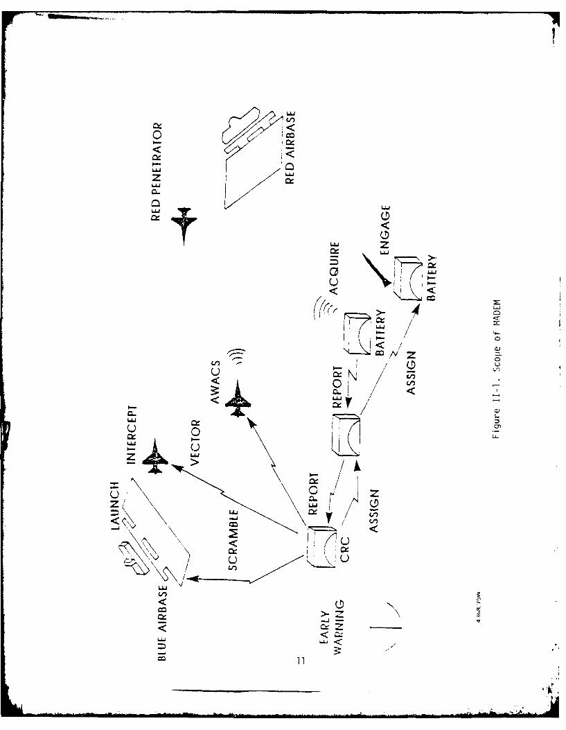
II-1 Scope of MAGEM 11
11-2 Typical Input Language File Entry 14
III-1 Example of Hexagonal Structure 18
111-2 Example of Modular Construction 20
111-3 MADEM Raid Planning Requirements 22
111-4 Formation Structure 23
111-5 Scenario Controls 25
111-6 MADEM Generated Air-to-Air Engagement 28
111-7 MADEM Generated Ground-to-Air Engagement 30
111-8 CRC Mode of Control 32
IV-l MADEM Action Cycle 38
IV-2 Blue Command/Control Structure 40
IV-3 Red Command/Contr6l Structure 41
IV-4 Red Attack Structure 46
IV-5 A Simple MADEM Scenario 47
IV-6 Red Wave Components 49
IV-7 Corridor Configuration 50
IV-8 A Typical Mission Profile 51
11-9 The Red Threat Planning Cycle 53
IV-1O Corridor Specifications 55
IV-11 Corridor Zones 56
IV-12 Terrain Representation 60
5.

LIST OF ILLUSTRATIONS (CONTINUED)
- gure Page
IV-13 Flight Path Example 61
IV-14 Calculation of interception Point 63
IV-15 Probability of Detection Curve 66
IV-16 Line-of-Sight Determination 67
IV-17 NIKE-HERCULES Ordnance Selection 94
1\-18 PATRIOT Ordnance Selection Decision Tree 95
IV-19 Directional Engagement Priorities 97
v-I MADEM Processor Configuration 100
VI-1 Locations and C2 Relationships 140
VI-2 Latitude and Longitude Overlay 141
VI-3 Missile Ranges 143
VI-4 First Wave Attack Specifications 145
VI-5 Second Wave Attack Specifications 146
VI-6 Sample Data Base File 148
6Smp aa oc sso JoForle Laguge48VI-7 User Oriented Input Language File 152
VI-8 Preprocessor Job Control Language 155
VI-9 Main Processor Job Control Language 158
VI-lO Volume Cards 160
VI-il Post Processor Job Control Language 162
VI-12 Post Run Purging JCL 164
VI-13 Result of Red Theater Plans 168
VI-14 First Wave Attack Plan 169
Vi-15 Result of Red Theater Plans 170
6
.'.t

LIST OF ILLUSTRATIONS (CONTINUED)
Fiqure Page
VI-16 Second Wave Attack Plan 171
VI-17 Sample Event Listing 172
VI-18 Number Of Units Created By Type 174
VI-19 Number Of Red Attacks On Blue Players 175
VI-20 Acquisitions Of Red FLTS By Blue Units 176
A-I Hex Specifications 178
A-2 Numbering Scheme For Level 6 Hexes Within ALevel 7 Cluster 180
A-3 Numbering Scheme For Level 1 Hexes Within ALevel 2 Cluster 181
A-4 C,'mbined Numbering Scheme For Level 6 HexesWithin A Level 8 Cluster 182
A-5 Sample Hex Addresses Within A Level 9 Cluster 183
A-6 Hex Directions At Level 6 185
A-7 Hex Directions At Level 7 186
SECTION IINTRODUCT IOI
The purpose of this manual is to cocument the Modular Air Defense
Model (MADEM) simulation. It is designed for use by analysts ;)o .iir to
use MADEM in a study. Programmers charged with maintaining or' modioing
the MADEM software are referred to the MADEM Programmer Manual.
Chapter II of this manual contains an executi.'e summary of AADEM! cnie
characteristics. An overview of the MADEM System is provided in Chapter
III. It is intended as a quick reference to MADEM's general capabiities
and limitations.
Chapter IV contains detailed documentation cf the orocesses moceec in
1MADE'm. It is followed by 3 detailed discussion of MADEM ope'ation 4ith
emprasis on specific input requiremerts in Chapter 1. An examrle case,
inCluding all inputs and required Job Control Language is oro1idec al
Chapter VI.
9
4
4 ~* * -

SECTION II
EXECUTIVE SUMMARY
A. PURPOSE, SCOPE, AND METHODOLOGY
The Modular Air Defense Effectiveness Model (MADEM) was developed by
the BDM Corporation to support a Defense Nuclear Agency (DNA) evaluation of
the role of nuclear weapons in NATO air, defense. MADEM encompasses the
entire NATO (Blue) air defense structure including generation of a system-
atic theaterwide Warsaw Pact (Red) attack plan. Figure II-1 illustrates
the scope of MADEM.
MADEM has several unique characteristics which distinguish it from
other Theater Level Air Defense Models. Most significant among these is
the use of a player-centered design in which key units and flights in the
air defense system are explicitly modeled. This approach also allows
modeling of individual unit perceptions based on the information that would
be available to the unit in a similar real world situation. In addition to
explicit unit modeling, MADEM also uses a list processing data storage
system to explicitly represent the command, control and communications
networks which link units in the air defense system. These explicit repre-
sentations of air defense system elements are combined with a hex based
coordinate system which allows maximum unit movement flexibility with
minimal data storage requirements. The result is a flexible model capable
of representing a variety of combat processes. Tab e 11-1 summarizes the
major processes modeled in MADEM.
While MADEM does extend many modeling aspects beyond what had been
previously achieved and does contain some unique characteristics, it is
like other models in that it must be used as a relative rather than an
absolute tool. Results generated by MADEM should be used only in this
context.
10
o-(--<
z
"Ii
a W.a
0 L/0
- 0-
I-u
NiN
3.111

TABLE 11-1, PROCESSES MODELED
PROCESSES LEVEL OF DETAIL
PLANNING OF AIR ATTACK MULTIPLE RAIDS AGAINST SPE-BY PACT CIFIC TARGETS BASED ON
STRATEGIC/TACTICAL CHARACTER-ISTICS OF BATTLE, AIRCRAFTAND TARGETS
ALLOCATION/ASSIGNMENT OF CRC/BOC/BTRY/INTERCEPTORPACT PENETRATORS INTERACTIONS AND AUTONOMOUS
OPERATIONS PLAYED EXPLICITLY
AIRCRAFT INITIATED COMBAT AIR-TO-AIR COMBAT AND AIR-TO-GROUND ATTACK EFFECTSBETWEEN INDIVIDUAL FLIGHTSASSESSED
GROUND-TO-AIR COMBAT EFFECTS OF INDIVIDUAL MISSILEFLYOUTS FROM SPECIFIC FIREUNITS AGAINST SPECIFIC AIR-CRAFT ASSESSED
C3 EFFECTS OF NUCLEAR WEAPONS/ACQUISITION CHARACTERISTICS/IFF/EARLY WARNING COMMUNICA-TIONS DELAY
12

B. DATA BASE DESCRIPTION
The data base size depends on the situation to be modelled. The
aircraft modeling characteristics are described, as well as how flights and
formations are formed. Flight profiles, the numbers of aircraft on
different air bases and system characteristics of the different air defense
systems are also specified. Probability of acquisition, detection and of
kills for the different system are described in the data base. MADEM also
has an input language for the specific scenario description. The command
structure and unit location as well as the general orders for the Red
attack are described in English-like sentences for user ease. Figure 11-2
shows a typical inpit language file entry.
C. PRIMARY OUTPUTS
MADEM is a discrete event simulation. A complete event trace is
available for all significant events. A "history" file is also generated
during the course of the simulation. This file can be used as input to a
post processor which recovers relevant statistical information in tabular
form. At present, records are kept on system acquisition, engagements,
kills, missiles fired, number of penetrators reaching target, and damage
levels for key units.
D. APPLICATIONS
Subsequent to its development, MADEM has been successfully used to
evaluate the performance of alternate threat forces and air defense force
capabilities in support of study efforts, and to compare and evaluate the
sensitivity of various assumptions about system performance capabilities on
overall theater air defense effectiveness. Table 11-2 summarizes MADEM's
potential application areas.
13
~-,.

USER INPUTS GENERAL ALLOCATION SCHEME TO MODEL, PLANNINGFUNCTIONS IN THE MODEL ASSIGN SPECIFIC AIRCRAFT TO HIT THETARGET, AND CALCULATES THE FLIGHT PLAN,
USER INPUT EXAMPLE:
RAID 1.CORRIDOR 1 LIMITS ARE 50.25 LAT 12,0 LONG, 50,33 LAT11.64 LONG
CORRIDOR 1 DEPTH IS 70 KM HEADING 245 DEG, SPREADANGLE 60 DEG.
BUFFER ZONE WIDTH IS 40 KM.
WAVE 1 START TINE IS 0430 HRS DAY 1 FOR 5 MIN.
TARGET TYPE HAWK BTRYS, 1 FORMATION, 150, OKM RANGELIMITS
2 TYPE 3 FORMATIONS
Figure 11-2. Typical Input Language File Entry
14

TABLE 11-2, MADEM APPLICATION AREAS
EFFECTS C3 STRUCTURES AND TECHNOLOGIES ON OVERALLCONFLICT OUTCOME
EFFECTS OF IMPROVED TECHNOLOGY IN WEAPONRY ANDACQUISITION/IDENTIFICATION SYSTEMS OF BOTH AIRCRAcTAND SAM UNITS
0 EXAMINATION OF POLICY AND DOCTRINE REGARDINGDEPLOYMENT AND TACTICAL OPERATION OF AIR DEFENSEUNITS FOR BOTH BLUE AND RED
* ROLE AND EFFECTS OF LOGISTICS ON THE AIR DEFENSEPOSTURE DURING A SUSTAINED CONFLICT
* ROLE OF NUCLEAR WEAPONS IN AN AIR DEFENSE/AIRDEFENSE SUPPRESSION ROLE
-15

E. OPERATING ENVIRONMENT
MADEM wa: developed on the Cyber 176 computer at the Air Force Weapons
Laboratory (AFWL). It is coded in CDC extended FORTRAN and Compass. In
its present form MADEM can be run on the CDC 6600, CDC 7600 and Cyber 176
computers using the FORTRAN compiler.
MADEM contains 22,500 FORTRAN source lines with 280 subroutines. The
131,000 word data storage area requires large core or extended core
storage.
16
_ _ _ _ _ _I

SECTION III
OVERVIEW OF THE MADEM SYSTEM
A. INTRODUCTION
The purpose of this chapter is to introduce the reader to the basic
architecture of MADEM and the major processes modeled. Both the archi-
tecture and processes modeled are documented in greater detail in Chapter
III.
B. MODEL ARCHITECTURE
1. MADEM1 Players
Active players modeled in MADEM include Control and Reporting
Centers (CRC), airbases, Battalion Operation Centers (BOC), fire units, and
Aircraft Warning and Control Systems (AWACS) as well as the Warsaw Pact
flights and formations. Non-players include targets such as Special
Ammunition Supply Points (SASP), nuclear surface-to-surface delivery units,
and command posts. Players are capable of acquiring and retaining per-
ceptions of their environment and making decisions based on a given logic
structure. By communicating with one another within the command structure,
p'ayers are capable of generating the necessary stimuli to sustain a con-
tinuing series of coordinated activities.
2. Geographical Accounting
MADEM uses a hexagonal coordinate structure for geographical
accounting. This permits greater efficienty and flexibility for movement.
The topological character of hexagons coupled with a unique numbering
system permits varying levels of detail. The smallest hexagon used in
MADEM is 9.45 kilometers wide. Seven such hexagons form a larger 25.0
kilometer hexagon. Other hexagon sizes are available but not used in
MADEM. Reference Figure li-l.
3. Actions Based on Perceptions
MADEM is a player centered model. All processes simulated in the
model are initiated by actions taken by player units. Players initiate
17

LEVEL 9CELADDRESS
/ 423151532
LEVEL 10CELL ADDRESS 5 34231615344 7 LEVEL 8
4 2 CELL ADDRESS~ 42316152
Figure III-1. Example of Hexa1gonal Structure
18

actions based on perceptions of the environment received through their
acquisition and communications devices. The nature and status of the
units' acquisition and communications devices will determine the extent to
which perceptual data is distorted. For example, it is possible for inter-
ceptors to incorrectly identify a Blue flight as a Red flight and fire on
it.
4. Modularity
The model was developed along functional lines so that each major
function exists as semi-independent section of the model. Each major
function is referred to as a module. The modules are further divided into
smaller segments each of which contains the logic for a single decision or
physical operation. The modules are tied together through a centralized
software control system that manages the overall functioning of the model.
This multi-module configuration is illustrated in Figure 111-2.
The modularity of MADEM simplifies the process of adding new
modules or modifying existing modules. Each can be accomplished with a
minimum amount of effort since all modules are linked both operationally
and functionally through the simulation control software.
5. MADEM Capabilities and Constraints
Besides modeling the fundamental air defense functions of
acquisition, identification, assignment, engagement and analysis, MADEM is
able to plan raids. It accomplishes this by matching available resources
against a given target base. Following a raid, MADEM assesses perceived
damage to the target base and the known attrition of threat aircraft and
schedules the next raid. This process is repeated as often as desired
without interruption of a production run.
The number of events and variety of activities that can be real-
istically expected to occur in a large scenario in a short time frame is
significantly large. For instance, a typical MACEM historical file con-
tains over 80 events printed for each second of battle (during intense
periods). For each event printed, three or more events occur but are not
printed.
Since most real life activities can not be precisely modeied or
predicted, one should treat the absolute output parameters of MADEM with
19
-- . ,

- PERCEPT
ASSIGN PONOER
3095178WBO
Figure 11-2. Ex ML IONo~a ontuto
20NRO

caution. They may or may not represent precise outcomes of given
scenarios. The principal value of MADEM lies in its ability to fairly
approximate a given situation for comparison and relative analysis of
scenario variations.
C. MAJOR PROCESSES MODELED
1. Red Threat Planning
a. Primary Input Data
(1) Warsaw Pact air base locations,
(2) Number and type of aircraft available at each air base (basing),
(3) Command structure for scheduling and rescheduling raids,
(4) Corridor locations and characteristics,
(5) Aircraft speed, altitude, and combat radius,
(6) Wave start times and durations,
(7) Flight types and formation descriptions,
(8) Strike criteria for target types by wave and raid
b. Red Threat Planning Capabilities
MADEM plans each wave and raid by matching formation and
targeting requirements with basing and corridor information. Subsequent
raids are based upon Warsaw Pact aircraft attrition, new targeting require-
ments, and perceptions of damage caused by previous raids. Figure 111-3
illustrates this scenario.
MADEM moves aircraft "flights". Each flight consists of a
grouping of homogeneous type aircraft scheduled against a preselected
target (targeting planned by MADEM). A "type flight" consists of a
specified number of aircraft, depending on the type target it is designed
to attack. Individual aircraft are not tracked, but are accounted for when
the flight is attacked and aircraft kills result.
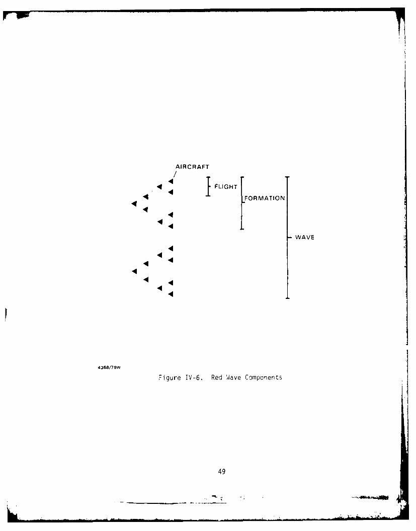
An aggregation of flights constitutes a formation (Figure 111-4),
formations constitute waves, and waves constitute raids. MADEM completes
two raids in a single iteration by assessing the previous raid and planning
the subsequent raid. Separate iterations may be run for each air defense
alternative.
21

AOf-<
4L)
AL
22I

L.
UL-
2.3
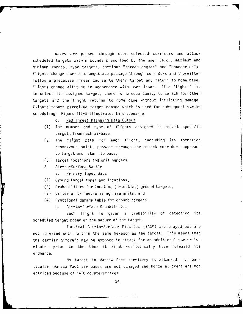
Waves are passed through user selected corridors and attack
scheduled targets within bounds prescribed by the user (e.g., maximum and
minimum ranges, type targets, corridor "spread angles" and "boundaries").
Flights change course to negotiate passage through corridors and thereafter
follow a piecewise linear course to their target and return to home base.
Flights change altitude in accordance with user input. If a flight fails
to detect its assigned target, there is no opportunity to serach for other
targets and the flight returns to home base without inflicting damage.
Flights report perceived target damage which is used for subsequent strike
scheduling. Figure 111-5 illustrates this scenario.
c. Red Threat Planning Data Output
(1) The number and type of flights assigned to attack specific
targets from each airbase,
(2) The flight path for each flight, including its formation
rendezvous point, passage through the attack corridor, approach
to target and return to base,
(3) Target locations and unit numbers.
2. Air-to-Surface Battle
a. Primary Input Data
(1) Ground target types and locations,
(2) Probabilities for locating (detecting) ground targets,
(3) Criteria for neutralizing fire units, and
(4) Fractional damage table for ground targets.
b. Air-to-Surface Capabilities
Each flight is given a probability of detecting its
scheduled target based on the nature of the target.
Tactical Air-to-Surface Missiles (TASM) are played but are
not released until within the same hexagon as the target. This means that
the carrier aircraft may be exposed to attack for an additional one or two
minutes prior to the time it might realistically have released its
ordnance.
No target in Warsaw Pact territory is attacked. In par-
ticular, Warsaw Pact air bases are not damaged and hence aircraft are not
attrited because of NATO counterstrikes.
24

MAX RANGE
PERCEIVED
50% DMAGESAM BUFFER ZONE
CORRIDOR
SAM BUFFER ZONE
ACTUAL 30 DAMAGE FB
PERCEIVED 40% DAMAGE FB
Figure 111-5. Scenario Controls
25

Damage to ground targets is assessed according to the nature
of the target. Some targets, such as air defense fire units, are either
100% destroyed or not, dependent upon a Monte Carlo process for the par-
ticular ordnance used (assumes the specific targets are the radars). Other
targets such as depots, command posts, and nuclear delivery units are
damaged in a cumulative manner based on the number and type of ordnance
used against the specific target.
c) Air-to-Surface Data Output
(1) The number and types of aircraft reaching their specified tar-
gets,
(2) Fractional damage of the given set of targets, and
(3) Air defense fire units neutralized.
3. Air-to-Air Battle
a. Primary Input Data
(1) NATO airbase locations with number and type aircraft,
(2) Aircraft ordnance loading and combat radius,
(3) NATO interceptor flight sizes,
(4) Probabilities of kill for Warsaw Pact and NATO air-to-air
ordnance types, and
(5) Operational availability of interceptors is addressed by randomly
withholding appropriate numbers and types from the model.
b. Air-to-Air Capabilities
The Control and Reporting Centers (CRC) scramble inter-
ceptors upon demands caused by the threat. They are scrambled when hostile
flights are detected but are not assigned to specific flights until air-
borne. Flight sizes are fixed in size based on user input. The flight is
vectored to an intercept point by the CRC (or AWACS) until within detection
range of the hostile flight. As the threat changes course, the intercept
point is relocated accordingly. Visual and/or radar acquisition occurs
when the interceptor flight approaches within acquisition range of the
hostile flight. Probability of kill is based on type of ordnance loadings
for both NATO and Warsaw Pact flights. Targets of opportunity may occur
when flights find themselves unexpectedly in close proximity to eacn other
26
(e.g., within 20 km). Interceptors return to their departure air base when
the hostile flight has been destroyed or when fuel and/or ordnance has been
expended. If communications to the CRC have been interrupted the flight
will return to its airbase.
Once interceptor flights are landed, a 60 minute (a variable
user input) delay time is incorporated in the model to account for
rearming, refueling, and minor repair time. Subsequent to this delay,
interceptors become available for new assignments. In the current model,
NATO airbases are assumed available to service returning interceptor
flights regardless of the amount of damage to the air bases, and aircraft
on the ground at the time of an attack are not destroyed.
c. Air-to-Air Data Output
(1) Flights acquired and engaged; aircraft destroyed,
(2) NATO interceptors destroyed.
4. Surface-to-Air Battle
a. Primary Input Data
(1) HIMAD and LOMAD Surface-to-Air Missile (SAM) fire unit locations,
(2) Detection/tracking/engagement envelopes for SAM units,
(3) Warsaw Pact aircraft attrition rates due to SHORAD units,
(4) Missile inventories and resupply rates,
(5) Threat assessment criteria (single, few, many hostile aircraft),
(6) Firing doctrine (e.g., shoot-shoot-look),
(7) Crew/system response times,
(8) Probability of detection of air targets,
(9) Probability of kill of air targets by SAM type,
(10) Azimuth limits (patriot) and dead zones, and
(11) Operational availability of SAM units is addressed by randomly
withholding, by use of a random number generator, appropriate
numbers and types from model input.
b. Surface-to-Air Capabilities
Early warning radars and fire units provide threat data to
CRC's. Detection ranges are based on radar line-of-sight with both earth
27
- -.

vsv. .. . . . .-- -- --0"
~ - - -
- - .7 " . . . - . . -- /. . .- 0 . - . . . -- - v . i - -.
. ." "-.. - . - - . - N^ . - . = ' - _ -- . - .- -- / ./ -.- - - . . ..
. . .=; - N - - N.-v-- - .N. Jk . .. .. - .
tA"
* = ..
NN ® ®®®® -
282
VS
-NcN~ N N ,--
-12 ~ --
> ' f 28

curvature and terrain masking considered. A threat can be masked and
remasked from a fire unit based on terrain elevations specified for every
25 km hexagonal area. Probability of detection is a function of range.
CRC's assign flight tracks to BOC's. BOC's assign tracks to
fire units depending upon the availability of the battery to engage the
flight. Fire units have the ability to detect hostile tracks directly if
undetected through the CRC. All targets have the same priority for attack
(e.g., first seen, first attacked) except that incoming targets are
attacked before outgoing targets. Priorities are established when fire
units are operating in an autonomous mode.
MADEM determines if the threat flight is within a three
dimensional engagement envelope of a fire unit and if the flight has been
detected. If both answers are yes, then MADEM schedules a "fire" and an
engagement occurs. Launching sequences are based on crew/system reaction
times and firing doctrine. Once an engagement has begun, it can not be
interrupted (e.g. , for masking problems). The firing doctrine for a HAWK
fire unit is shoot-shoot-look on the first engagement unless there are less
than nine missiles remaining on site. On subsequent engagements of if less
than nine missiles remain at the fire unit the doctrine changes to shoot-
look-shoot. The Patriot system has the capability of firing multiple
simultaneous missions.
SHORAD Fire units are implicitly modeled; they cause
attrition of hostile flights uniformly over all NATO territory.
Nike Hercules, HAWK, and Patriot units are resupplied with
missiles in accordance with prescribed resupply rates.
Figure 111-7 illustrates two MADEM generated formations with
HAWK engagements.
c. Surface-to-Air Data Output
(1) Number of aircraft detected and acquired,
(2) Number of missiles fired,
(3) Number of aircraft destroyed.
29

- -. -. N v .N . , v-.>.-- -~ .- ..-
C7)
LWL
CIO C
- .. .. -. U .'. - ----.. .-- - - ".-. - . . -
- - ,-'--
-=
- ---- - ----/ - . / -- _ - -Nv- v " . -,
30"
CC 661 -d I

5. Command, Control and Communications (C )
a. Primary Input Data
(I) C3 relationships and location of nodes,
(2) Primary Target Lines (PTL) for SAM units, and
(3) Probability of misidentifying a flight of aircraft
b. C3 Capabilities
For the base case, the highest state of air defense alert is
assumed. That is, air defense elements are in Emergency Defense Positions
(EDP) and the appropriate degree of readiness of each available system has
been achieved.
The base case plays a CRC mode of control. This means the
CRC receives threat data from early warning radars and fire units and
assigns targets to air bases and interceptors or to SAM BOC's and fire
units. Fire units may be at battery level in the case of Nike Hercules, or
at platoon level in the case of HAWK and Patriot. In this mode of control
the CRC does not coordinate with other CRC's and hence it is possible that
two or more CRC's may assign different air defense elements the mission of
attacking the same target at the same time. If a fire unit can not engage
an assigned flight, a message is sent to the BOC and hence to the CRC so
stating. The target is then reassigned by the CRC. No alternate com-
munication routings are possible. Message traffic is delayed four (4)
seconds f)r each transmission. Reference Figure 111-8.
The present state of MADEM does not permit explicit modeling
of various Weapons Engagement Zones (WEZ) because Gf the complex geometry
involved. A modified WEZ is played, however, by prohibiting HIMAD units
from firing at targets below a specified altitude where probability of kill
is less and by prohibiting LOMAD units from firing at targets above a
specified altitude regardless of geographical locations of fire units.
Interceptors operate anywhere as directed by the CRC.
Minimum burst altitudes are prescribed for various yield
nuclear SAM warheads.
Imperfect identification is played. Once a hostile target
is misidentified it can be correctly identified at a later time by inter-
ceptors at time of engagement. Subsequently, the CRC may correct its
31

L.
\
32 0

misperception. Misidentification of friendly aircraft may be corrected
only if the aircraft has not been assigned to a SAM unit.
AWACS can detect hostile flights and vector fighter inter-
ceptors but is not attacked by hostile flights. No NATO aircraft are
dedicated to AWACS defense.
Air defense units assume the highest state of alert and
revert to autonomous operations when communications to higher organizations
are lost. This can occur when a CRC or BOC has been neutralized by hostile
flights or when the effects of Electromagnetic Pulse (EMP) destroys com-
munications equipment. For SAM fire units, priorities for engagement are
to flights approaching along the unit's primary target line, to all other
incoming flights, and finally to outgoing flights. For air base defense, a
flight of interceptors is scrambled to one of seven (randomly selected)
hexagons adjacent to the airbase by a "dummy CRC". When a hostile flight
is detected by the airborne flight, the "dummy" CRC scrambles all available
flights to adjacent hexagons where air-to-air battle ensues in accordance
with target of opportunity rules of engagement. The dummy CRC lands the
interceptors when the threat has passed.
6. Electronic Warfare (EW)
a. Primary Input Data
Degraded detection and engagement ranges.
b. EW Capabilities
In an EW environment, MADEM degrades the operational charac-
teristics of all NATO air defense units uniformly across the defended area
by type system. The worst electronic countermeasure threat for each type
system is used to degrade the performance of the system. Frequency and
power characteristics of jammers are considered in arriving at the degraded
performance characteristics of NATO air defense units.
7. Nuclear Environment
a. Primary Input Data
(1) Criteria (size/altitude of threat flights and minimum normal
burst altitude) for the CRC to make assignments of nuclear
weapons by type warhead, and
(2) Probability of kill of nuclear air defense weapons. .33
LL

b. Nuclear Capabilities
Nuclear air defnese missiles are employed based on a logic
criteria that considers threat size, altitude, and Minimum Normal Burst
Altitude (MNBA). It is assumed that separation distances between aircraft
flying above MNBA are such that a nuclear burst will destroy at most a
single plane.
When a nuclear burst occurs, all communications within the
same hexagon as the burst are disabled for the duration of the raid(s). If
communictions are lost in this manner, subordinate units operate in an
autonomous mode.
34

SECTION IV
MODEL SPECIFICATIONS
A. INTRODUCTION
This chapter documents the basic specifications of the MADEM simula-
tion. Its purpose is to explain the structure and assumptions which
underly the processes modeled in MADEM. While this chapter deals with the
processes modeled in some detail, it does not attampt to cover the actual
implementation of the model in the FORTRAN code. Users who require more
detailed information on model implementation are referred to the MADEM
Programmer Manual and Source Listings.
B. SIMULATION ARCHITECTURE
1. Modularity
The model was developed along functional lines so that each major
function exists as a semi-independent section of the model. Each major
function is referred to as a module. The modules are further divided into
smaller segments each of which contains the logic for a single decision or
physical operation.
Each function represents some specific air activity or event.
For example, the perceptions of enemy aircraft are handled in a module
separate from the module that makes decisions to fire on those aircraft.
Within the perception module are the various segments such as the one that
determines line of sight intervisibility between a battery radar and a
flight of aircraft.
The various segments and modules of the model are tied together
through a centralized software control system that manages the overall
functioning of the model. This centralized software control system, in
addition to providing basic data processing functions such as input and
output control, provides the sophisticated list processing technique which
is the basis for much of the power of the MADEM architecture. Module
functions are summarized in Table IV-l.
35
_____ ____ ____
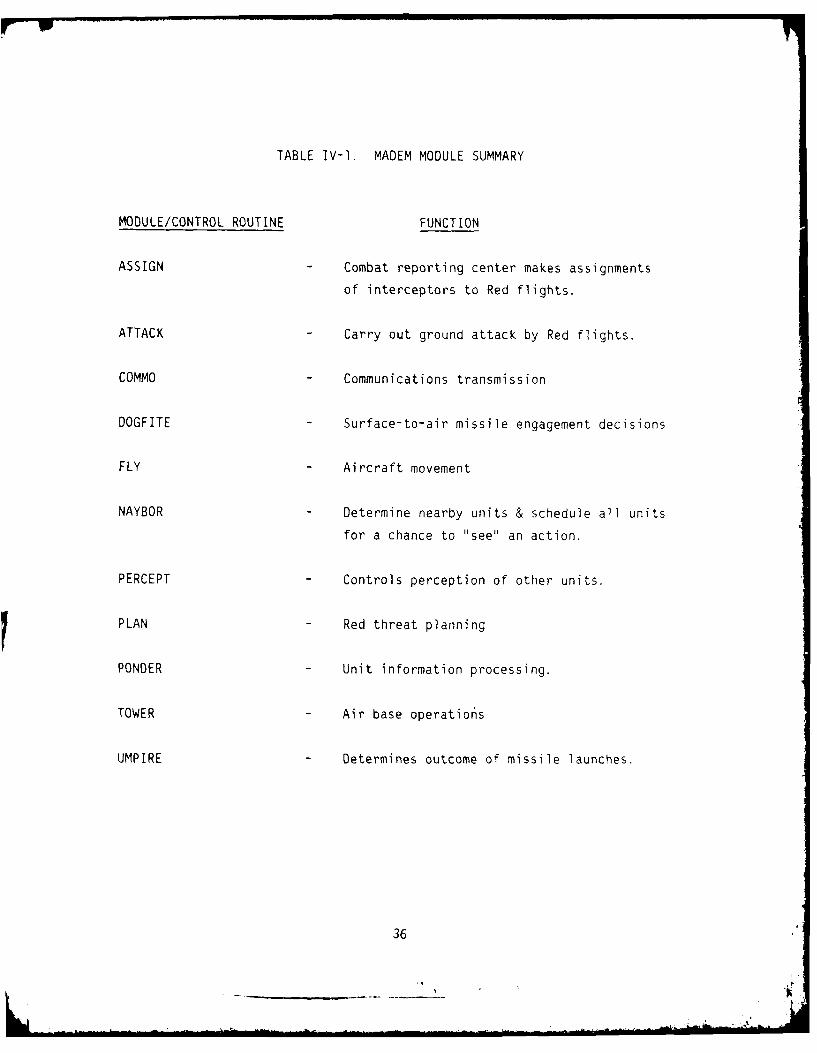
TABLE IV-I. MADEM MODULE SUMMARY
MODULE/CONTROL ROUTINE FUNCTION
ASSIGN - Combat reporting center makes assignments
of interceptors to Red flights.
ATTACK - Carry out ground attack by Red flights.
COMMO - Communications transmission
DOGFITE - Surface-to-air missile engagement decisions
FLY - Aircraft movement
NAYBOR - Determine nearby units & schedule all units
for a chance to "see" an action.
PERCEPT - Controls perception of other units.
PLAN - Red threat planning
PONDER - Unit information processing.
TOWER - Air base operatio6s
UMPIRE - Determines outcome of missile launches.
36

2. Discrete Events
MADEM is a player centered, discrete event simulation. The
simulation is made up of three fundamental components - entities, actions
and processes. Entities are the units which actually participate in battle
as active players. These player units may take actions which affect their
environment including other units. The processes simulated in MADEM are,
in fact, composed of many discrete actions taken by entities interacting
with each other in the battle area over time. Units take actions in
response to their perception of the environment. When an action is taken
the unit schedules an event or series of events which corresponds to the
action to occur some time in the future of the battle. The time between
the decision to take an action and the scheduled time of the event reflects
the time lag inherent in the action being taken.
Each player must schedule many events in the course of the simu-
lation. As a result, the number of events that must be managed by the
simulation in a typical scenario is quite large. For example, an average
MADEM historical tale contains over 240 events for each second of battle.
The interaction for these events is controlled by the Simulation Control
Software (SCS). The SCS sorts all scheduled events to insure a logical
progression of events. It also interprets the events as they occur in the
sequence of battle and activates the appropriate software module to simu-
late the desired processes. When a player unit is destroyed or incapa-
citated to the point where its future events cannot be expected to occur,
the SCS withdraws the unit's future events from the schedule.
3. Action Cycle
Model processes, as represented by the software modules listed in
secrtion 1I-B-1, are driven by a three phase, player centered, action cycle.
Figure IV-] illustrates this cycle. The cycle is initiated by an action
taken by a player unit. The initiating action is usually a movement.
However, other actions including attacks, deaths and messages may also
initiate the cycle. These initiation actions are then perceived by player
units through their respective acquisition and communications devices. The
nature and status of the units acquisition and communications devices will
37

ACTIONS
MOVEMENTSATTACKSDEATHSMESSAGES
4368/79W
Figure IV-l. MADEM Action Cycle
38
determine the extent to which perceptual data is distorted. For example,
it is possible for interceptors to incorrectly identify a Blue flight as a
Red flight.
Perceptual data is then pondered to determine the appropriate
action for the perceiving unit to take. The ponder phase of the cycle is
analogous to a units consideration of actions to be taken in response to
external events. The time a unit requires to ponder and react to percep-
tions varies with the unit type and the complexity of the action perceived.
Actions resulting from the ponder phase reinitiate a new cycle.
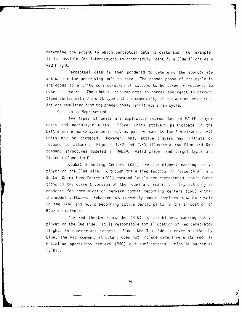
4. Units Represented
Two types of units are explicitly represented in MADEM player
units and non-player units. Player units actively participate in the
battle while non-player units act as passive targets for Red attacks. All
units may be targeted. However, only active players may initiate or
respond to attacks. Figures IV-2 and IV-3. illustrate the Blue and Red
command structures modeled in MADEM. Valid player and target types are
listed in Appendix E.
Combat Reporting Centers (CRC) are the highest ranking active
player on the Blue side. Although the Allied Tactical Airforce (ATAF) and
Sector Operations Center (SOC) command levels are represented, their func-
tions in the current version of the model are implic!i. They act only as
conducts for communication between combat reporting centers (CRC) within
the model software. Enhancements currently under development would result
in the ATAF and SOC's becomming active participants in the allocation of
Blue air defenses.
The Red Theater Commander (RTC) is the highest ranking active
player on the Red side. It is responsible for allocation of Red penetrator
flights to appropriate targets. Since the Red side is never attacked by
Blue, the Red command structure does not include defensive units such as
battalion operations centers (BOC) and surface-to-air missile batteries
(BTRY).
39

ATAF
SOC
*NOTE: TEMPORARILY LAUNCHEDFROM A. B. EVENTUALLY
TR RETURNS TO A.B.
4368,/79W
Figure IV-2. Blue Command/Control Structure
40

ERT I
FIT FITNOTE: TEMPORARILY LAUNCHED
4368'/9W
Figure IV-3. Red Command/Control Structure
41
j6t

C. DEFINITIONS OF PLAYERS
1. Combat Reporting Centers (CRC)
The combat reporting centers are the highest ranking active
player on the Blue side. CRC's control the actions of all subordinates
which are capable of communication with the CRC. The CRC's are responsible
for acquisition and identification of threat aircraft within their zones of
control. They are also responsible for allocation of defense units to
incoming Red penetrators.
In the course of fulfilling these responsibilities the CRC units
perform the following functions:
(1) Acceptance of early warning information
(2) Determination of type of subordinate to engage threats
(3) Request of interceptor launch by air bases
(4) Assignment of threats to specific subordinates
(5) Receipt and processing of engagement status information from
subordinates
(6) Vectoring of interceptors to assigned threats
2. Red Theater Commander (RTC)
The Red theater commander (RTC) is the highest ranking active
player on the Red side. The RTC is the core of the Red Threat planning
process. It interprets general attack specifications input by the user and
converts them to a set of specific flight plans which are used to carry out
the attacks. The RTC controls execution of waves and raids as well as the
channeling of penetrator flights through appropriate corridors. In
addition, the RTC chooses specific targets to be attacked based on target
location, damage level and available aircraft types.
In the course of fulfilling these responsibilities the RTC per-
forms the following functions:
(1) Interprets user input attack specifications
(2) Perceives location and damage level of potential targets. (Red
perceptions may differ from reality)
42

(3) Constructs general resource limits for each wave and raid.
(4) Defines sppciic formation components
(5) Determines takeoff times for flights which make up the formations
(6) Sets flight plans (incluJing rendezvous points) for each flight.
(7) Allocates flights to specific targets
3. Air Bases (AB)
Air bases are the on'y player unit type used by both the Red and
Blue sides. Both Blue and Red air bases are capable of keeping track of
the number and type of aircraft on the air base as well as the status of
eac. aircraft type in terms of launch capability.
Air bases perform the following functions:
(1) Accept launch requests from CRC or RTC.
(2) Launch available aircraft on request
(3) H.ld returning aircraft for refueling, rearming, etc.
(4) Antonomous launching of aircraft to CAP orbit when not under
control of a CRC. (Blue only)
4. Battalion Operations Centers (BOC)
Battalion operations centers (BOC) exist only on the Blue side.
BOC's report to CRC's and comma- 1 surface-to-air batteries. BOC's are
responsible for coordinating assignment of incoming Red targets to SAM
batteries under their command. They are also responsible for monitoring
engagements and reporting results to the CRC. Three types of BOC are
currently simulated: HAWK, NIKE-HERCULES and PATRIOT.
In the course of fulfilling these responsibilities the BOC's
perform the following functions:
(1) Acquisition/IFF of threat aircraft
(2) Acceptance and passage of early warning information to the CRC.
(3) Providing engagement status reports to the CRC.
(4) Acceptance of penetrator assignments from the CRC
(5) Digestion of information on assigned threats and scheduling o"
subordinates' engagements.
(6) Prioritization of threats
43

(7) Assignment of threats to particular batteries
(8) Receipt and prccessing of engagement and battery status reports
from subordinate:,
(9) Antonomous selection of threats for engagement, when not under
control of CRC
5. Batteries (BTRY)
Surface-to-Air batteries (BTRY) exist only on the Blue side.
BTRY's report to BOC's and are composed of multiple time units. BTRY's are
the lowest ranking active player on the Blue side. BRTY's perform the
following functions:
(1) Acquisition/IFF of threat aircraft
(2) Passage of early warning information to BOC
(3) Acceptance of assignments from BOC
(4) Providing engagement and battery status reports to BOC
(5) Digestion of information on assigned threats
(6) Allocation of fire units to engage threats
(7) Reloading and request for resupply
(8) Autonomous operation when not under control of BOC.
6. Aircraft Flights (FLT)
Flights (FLT) are the basic maneuver unit in MADEM. They exist
on both the Blue and Red sides. Flights consist of one or more aircraft of
the same type launched from the same air base. jhts are unique in that
they are temporary entities. In response to an order from a CRC or RTC an
air base constructs a flioht of the requested type from the available
aircraft on base. Upon launch a new flight entity is created. This entity
acts as a player unit in the battle until it is either destroyed or returns
to base. While the flight is airborne it reports directly to the CRC that
commands its originating air base. When the flight returns to base it
ceases to exist as a separate player entity and its component aircraft are
returned to the air base's pool. While airborne, flights perform the
following functions:
(1) Move on a 9.45 km hexagonal coordinate system.
44

(2) Fly a sequence of straight-line segments
(3) Rendezvous with other flights to form formations which proceed
against assigned targets
(4) Perform maneuvers at checkpoints between flight-path segments,
possible maneuvers include:
* change direction
* change velocity
* initiate altitude change
(5) Check fuel on each move and head home when supply is low.
(6) Each movement of a flight results in a new opportunity for other
players to acquire and identify it.
D. NON-PLAYERS
In addition to the player units described in the previous section,
MADEM also contains a variety of non-player units. These Blue units are
non-players in the sense that they act only as targets for Red attacks.
These passive target units may be used to represent a wide variety of
significant penetrator targets which have no active air defense capability.
A complete listing of non-player unit types is contained in Appendix E.
E. DETAILED PROCESSES
1. Red Threat Planning
a. Planning Process Overview
1) Red Attack Structure
The Red Attack is carried out in a series of raids each
of which is made up of a number of waves. Raid and wave start times are
generally sequential and result in an attack structure similar to Figure
IV-4. Each raid and its component waves are planned by matching formation
and targeting requirements with air base and corridor locations. Subse-
quent raids are based upon Red aircraft attrition, new targeting require-
ments, and perceptions of damage caused by previous raids. Figure IV-5
illustrates a simple MADEM scenario.
45
L ... F

RAID 1 '1 I RAID 2
WAVE 1- - WAVE 1
-- WAVE 2 --- WAVE 2--H
BLUE TIME/DISTANCE RED
SIDE SIDE
4368"79W
Figure N1-4. Red Attack Structure
46

IILI
0+<
4 47

The basic maneuver unit in MAQEM is the "Flight". Each
flight consists of aircraft of the same type scheduled against a specific
target. Flight types consisting of specified numbers of aircraft are
assigned to formation types by the user. (Figure IV-6). Individual air-
craft are not tracked. However, they are accounted for when the flight is
attacked and aircraft kills result.
Flights are assembled from aircraft located on the air
bases. Each air base keeps track of the number and type of aircraft on the
base. All bases have user specified recovery to launch delay times asso-
ciated with aircraft types which determine the rate at which flights can be
launched. Only complete flights may be launched. If there are insuf-
ficient aircraft on the base to assemble a desired flight type, the flight
is not launched and the aircraft remain on the base as surplus for the next
raid.
Flights launched from the air bases rendezvous to form
formations. Formation types are assigned to attack various target types by
the user. Individual formations are assigned to attack individual targets
by the PLAN module. Formations launched during the same specified time
period constitute a wave.
Waves pass through user specified attack corridors and
attack scheduled targets within bounds prescribed by the user (e.g.,
maximum and minimum ranges, type targets, corridor "spread angles" and
"boundaries"). Figure IV-7 illustrates a typical corridor. Normally these
corridors will be cleared of Blue SAM batteries by the first Red flights
entering the corridor. Flights change course to negotiate passage through
corridors and thereafter follow a piecewise linear course to their target
and return to home base. Flights also change altitude during their
missions in accordance with user input mission profiles. If a flight fails
to detect its assigned target, there is no opportunity to search for other
targets and the flight returns to home base without inflicting damage.
Flights report percieved target damage which is used for subsequent strike
scheduling. Figure IV-8 illustrates a typical mission profile.
48
_ _.i .. m - .... . . - NeiwliI oll . ..
AIRCRAFT
4 I. FLIGHT
4 FORMATION
WAVE
44

MAX RANGE
PERCEIVED50% DAMAGE - - -
SAM BUFFER ZONE
CORRIDOR
SAM BUFFER ZONE
MIN RANGE
ACTUAL 30% D3AMAGEPERCEIVED 40% DAMAGE FEBA
Figure IV-7. Corridor Configuration
50
L ..-*

0~ zU. uw u
cc-
51 -

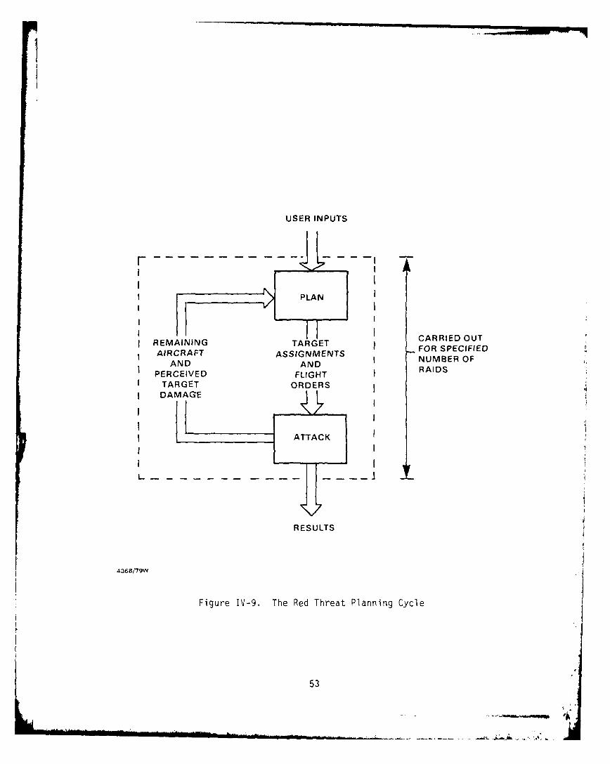
2) The Planning Cycle
The cyclical threat planning process used by MAOEM is
illustrated in Figure IV-9. At the beginning of a run the user inputs the
specifications for each raid (listed in section C.l.b). Target assignments
and corresponding flight orders are then generated by the PLAN module
subject to aircraft resource constraints. After the initial raid has been
carried out, the surviving Red aircraft return to their bases and report
percieved target damage levels to the PLAN module. If subsequent raids
have been specified by the user, the PLAN module adjusts target priorities
based on its remaining aircraft resources and generates new target assign-
ments and flight orders for the next raid. Once the process has been
initiated by user inputs the planning and attack process is self contained.
All subsequent raids will be carried out without user intervention.
3) Planning Stages
Red threat planning is carried out in four major stages
which may be summarized as follows:
(1) Corridor Boundary Specification - Attack corridors must be.
respecified for each raid.
(2) Overall Resource Allocation - User specified formation to target
type assignments are compared to available formations by type.
Assignments are proportionally adjusted to account for descrep-
ancies between user specified requirements and available
resources for each raid.
(3) Target Assignment - Individual formations are assigned to
specific targets based on formation, availability and specific
target selection criteria for each wave.
(4) Flight Scheduling - Orders for specific flights to join forma-
tions and attack specific targets are generated for each wave.
These orders include launch times and mission profiles.
Each of these stages is composed of a number of steps. The detailed
operation of each stage is discussed in the following sections - C.l.d,
C.l.e, C.l.f, and C.l.g.
52
1
USER INPUTS
I II
I PLANI I
I II
I ECARRIED OUTE GTARGET FOR SPECIFIED
AIRCRAFT ASSIGNMENTSAND AND NUMBER OF
PERCEIVED FLIGHT RAIDS
TARGET ORDERS, DAMAGE /,
1I
I ATTACK
1 I
RESULTS
A368i7gw
Figure IV-9. The Red Threat Planning Cycle
53

b. Corridor Boundary Specifications
Attack corridors must be specified by the user for each
raid. Required inputs for each corridor include the corridor limit loca-
tions, corridor heading, spread angle, and buffer zone width. The rela-
tionship of these inputs to a hypothetical attack corridor is illustrated
in Figure IV-lO.
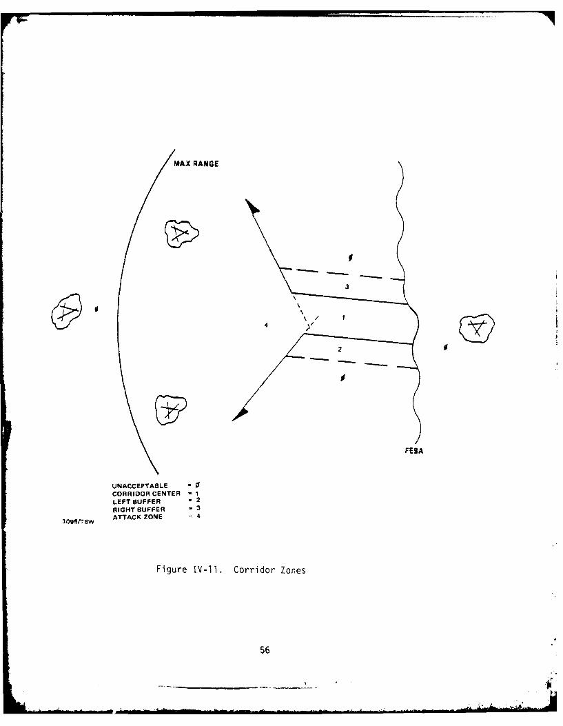
Processing of these corridor specifications by the plan
module results in creation of a set of geographic zones for each corridor.
These zones, which are illustrated in Figure IV-ll, are used in the target
assignment stage of planning to determine the geographic suitability of
specific targets. All targets in zones 1 and 4 are acceptable, while
targets in zone 0 are unacceptable. HAWK batteries located in zones 2 and
3 are acceptable. However, all other targets in zones 2 and 3 are
unacceptable. The purpose of this target classification scheme is to
insure that the corridor and its buffer zones are cleared of Blue units
which can shoot into the corridor center.
c' Overall Resource Allocation
The total available aircraft resources are allocated to user
specified target types for each raid. This process attempts to reconcile
any descrepancies between the attack resource assignments for each target
type input by the user with actual resources available. This stage of the
planning process is carried out in the following three steps:
(1) Determine for each wave the number of aircraft, flights and
formations required to attack all of the target types specified
by the user.
(2) Match each air base to the closest attack corridor and calculate
the number of aircraft (by type) available on each base.
Determine the total number of aircraft available to assemble
flights and formations.
(3) If the potential target is acceptable, an available formation is
assigned to attack it in the current wave. If it is not accept-
able, step (1) is repeated and a new potential target is examined
for geographic suitability.
54

MAX RANGE
SAM BUFFER ZONE BUFFER WIDTH
G ~ADN LIMITS
SPREAD---
SAM UFFE ~ ABUFFER WIDTH
FESA
095flSw
Figure IV-1O. Corridor Specifications
55
MAXRANGE
300
4
2 0
FEBA
UNACCEPTABLE =
CORRIDOR CENTER = 1LEFT BUFFER - 2RIGHT BUFFER - 3
3 095/1w ATTACK ZONE - 4
Figure IV-l1. Corridor Zones
56

Execution of these three steps for all available formations results in a
list of formation to target assignments, each formation is then assembled
from flights launched from the airbases. Although all of the flights in a
formation are assigned to attack the same target, their individual mission
profiles may vary considerably. This variation is particularly pronounced
for flights originating at different airbases which must rendevous to form
a formation. The process of flights and their corresponding mission pro-
files is carried out in the Flight Scheduling Stage.
d. Flight Scheduling
Flight scheduling is the last stage in the Red Threat
Planning Process. It is performed for each wave in the current raid and
consists of generating a series of orders for each flight required to make
up the formations specified in the target assignment stage. Flight
scheduling is a two step process which may be summarized as follows:
(1) Determine the rendevous point for each formation. The rendezvous
point is calculated as the center of gravity of the air bases
weighted by the number of aircraft in the flights to be launched
from each base.
(2) Construct a series of orders for each flight which instruct it on
the actions to be carried out at specified locations. These
orders cause the flight to climb to its rendezvous point, wait
for other flights in the formation, proceed to the target through
the corridor, carry out the attack and return to base. A flight
profile of this type is shown in Figure IV-8. Altitudes at
various phases in the mission are specified by the user in the
flight data base.
(3) If a discrepancy exists between the required and available air-
craft, the allocation of formation types to target types is
proportionally adjusted accross target types until the actual
number of formations assigned equals the number available.
Execution of these three steps results in a set of maximum aircraft
allocations for each formation and target type. These maximum allocations
are then used to guide the Target Assignment Stage.
57
LM"

e. Target Assignment
An assignment of formations to specific targets is made for
each wave in the current raid. Assignments are made subject to the maximum
allocation constraints which were calculated in the Overall Resource Allo-
cation Stage. Target assignments are made in a three step process which
considers formation type availability and target selection criteria. This
process may be summarized as follows:
(1) For each available formation examine the perceived damage level
of potential Blue targets. Potential targets are stratified by
types which are matched to formation types specified by the user.
The number of formations available by type has already been
determined in the resource allocation stage. Only targets of the
proper type are examined.
(2) Select the least damaged potential target and determine its
geographic suitability. Suitability is determined relative to
the closest attack corridor and the Red air bases to which the
corridor has been matched in the resource allocation stage. In
order to be acceptable, a potential target must be within minimum
and maximum range and be located within the corridor zones set in
the corridor boundary specification stage. (see figure C-8).
Execution of these steps for each formation which has an assigned target
completes the four stage planning process. All flights now have their
orders and are ready to carry out the raid without further intervention
from the plan module.
2. Aircraft Movement
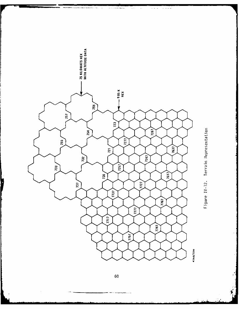
a. Terrain Representation
The aircraft movement process in MADEM is the principal
driver of simulation events; once an attack is set in motion, the dynamic
parallel/serial reactions of defenders are scheduled based primarily on
events related to the position and movement of penetrating aircraft.
Terrain in MADEM is represented on a discrete, two dimensional geographic
coordinate system whose points represent centers of hexagonal regions. The
lowest level (smallest) hexes currently represented in MADEM are 9.45 km
58
h ,. " ll

from center to center; this is the basic resolution or level of uncertainty
in the actual position of aircraft. Appendix A discusses the hex coordi-
nate system in more detail. Aircraft altitude in MADEM is represented on a
continous coordinate defined from local terrain altitude; local terrain
altitude is currently defined for second level hexes, which are 25 km from
center to center. The choice of terrain resolution has to date been
dictated by the objectives of minimizing memory requirements for model
execution while retaining the capability to represent the entire central
region of NATO's European theater. Figure IV-12 depicts the hex rela-
tionships of terrain representation and coordinates in MADEM.
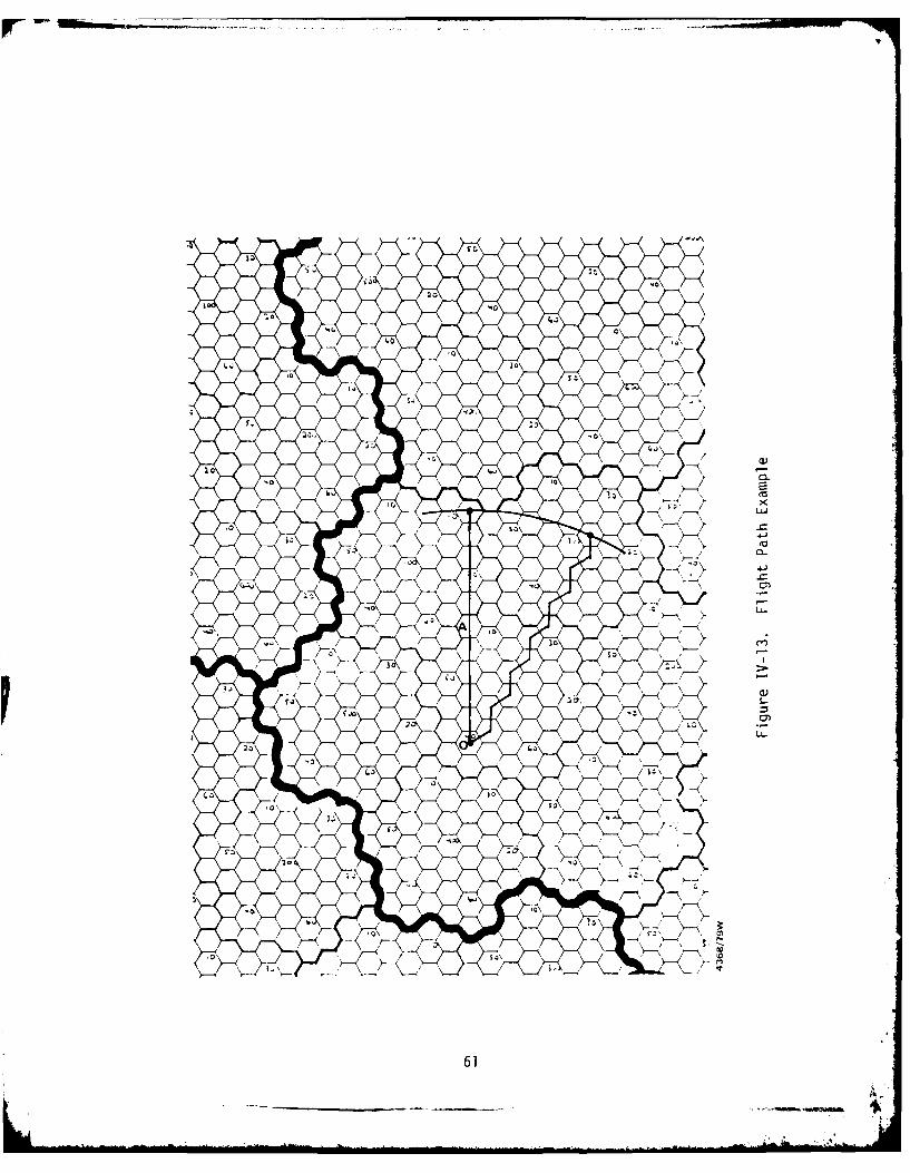
b. Movement Mechanics
Aircraft movement takes place with 3 degrees of freedom;
however, there is no representation of aerodynamic constraints on aircraft
motion. Flight paths consist of straignt line segments from hex center to
hex center; aircraft altitude changes are linear with respect to hexes
traversed. Aircraft move at two nominal speeds in MADEM, "cruise" and "air
combat"; both speeds are effective ground speeds and are user input for
each flight type. Because of anisotropism introduced by hex topology, path
lengths in the hex system are not necessarily equivalent to cartesion
distances. Figure IV-13 shows an example; flight path A begins from the
origin 0 and traverses 10 hexes, or 94.5 km in the hex coordinate system.
Flight path B also terminates 94.5 km from the origin 0; however, flight
path R traverses 12 hexes, or 113.4 km in the hex coordinate system. In
order to deal with this problem, "hex" velocity for a flight of aircraft is
increased by an amount directly proportional to the additional distance (if
any) traveled in the hex coordinate system. For the example case in the
figure, the nominal "cartesian" speed along flight path B is increased by
(113.4/94.5) or a factor of 1.20.
c. Formation Structure
Aircraft movement in MADEM occurs for "formations" and
"flights" of aircraft; formations can consist of multiple flights which in
turn consist of one or more aircraft of a generic class. Four generic
classes are represented: interceptors, (i.e., defensive air-air systems);
59
4r
0 O4C
040
LA
M 6
MD)
I.
61L

penetrating fighters with air-air capabilities; penetrating fighter-bombers
with air-ground and optional air-air capabilities; and penetrating bombers
with air-ground capabilities only. Up to twenty separate types of aircraft
can be represented in each generic class.
Characteristics of aircraft movement processes differ some-
what between interceptors and offensive aircraft flights. Interceptor
flight paths are based on orders from a CRC to a flight assigning either an
orbit station near the CRC or a hostile flight to be engaged. Actual
calculation of intercept points is treated in the discussion of air-air
engagements; however, interceptor flights proceed from their present posi-
tion to the calculated intercept point or orbit station by the most direct
route from their present position. Interceptor flights do not form larger
formations or maneuver in attacking an assigned target; for example, 2
flights assigned to the same target move independently to the calculated
intercept point, as shown in Figure IV-14. Figure IV-14 also indicates the
segments each flight would traverse in moving towards its objective.
d. Interceptor Characteristics
When interceptor flights are airborne but are not actively
engaging hostile aircraft, they occupy orbit stations positioned nea-
either their commanding CRC or their home air base. While interceptor
aircraft are orbiting, they are assumed to remain in the designated orbit
hex at a fixed altitude. Multiple flights are assumed to be able to occupy
the same orbit station. CRC's position orbiting interceptor flights
randomly within hexes adjacent to their location; air bases, when auto-
nomous, orbit interceptors over their location.
e. Penetrator Characteristics
Penetrating fighters, fighter-bombers and bombers flight
paths are all determined in the planning module. The planner generates a
flight path consisting of a series of straight line "legs". Changes in
heading and altitude are arbitrary between legs, allowing operationally
realistic penetration profiles to be developed. Penetrator flights move on
linear segments between hex centers in the same fashion as interceptors;
however, the hex centers are chosen to minimize deviation from the flight
62
______ ___ oi

63
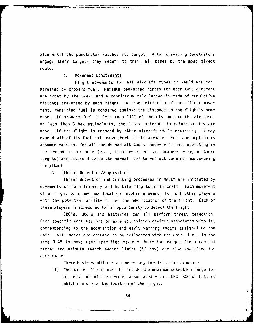
plan until the penetrator reaches its target. After surviving penetrators
engage their targets they return to their air bases by the most direct
route.
f. Movement Constraints
Flight movements for all aircraft types in MADEM are con-
strained by onboard fuel. Maximum operating ranges for each type aircraft
are input by the user, and a continuous calculation is made of cumulative
distance traversed by each flight. At the initiation of each flight move-
ment, remaining fuel is compared against the distance to the flight's home
base. If onboard fuel is less than 110% of the distance to the air base,
or less than 3 hex equivalents, the flight attempts to return to its air
base. If the flight is engaged by other aircraft while returning, it may
expend all of its fuel and crash short of its airbase. Fuel consumption is
assumed constant for all speeds and altitudes; however flights operating in
the ground attack mode (e.g., fighter-bombers and bombers engaging their
targets) are assessed twice the normal fuel to reflect terminal maneuvering
for attack.
3. Threat Detection/Acquisition
Threat detection and tracking processes in MADEM are initiated by
movements of both friendly and hostile flights of aircraft. Each movement
of a flight to a new hex location invokes a search for all other players
with the potential ability to see the new location of the flight. Each of
these players is scheduled for an opportunity to detect the flight.
CRC's, BOC's and batteries can all perform threat detection.
Each specific unit has one or more acquisition devices associated with it,
corresponding to the acquisition and early warning radars assigned to the
unit. All radars are assumed to be collocated with the unit, i.e., in the
same 9.45 km hex; user specified maximum detection ranges for a nominal
target and azimuth search sector limits (if any) are also specified for
each radar.
Three basic conditions are necessary for detection to occur:
(1) The target flight must be inside the maximum detection range for
at least one of the devices associated with a CRC, BOC or battery
which can see to the location of the flight;
64

(2) The flight must be within the azimuthal scan sector for the
device;
(3) Radar line-of-sight must exist from the acquisition device to the
target.
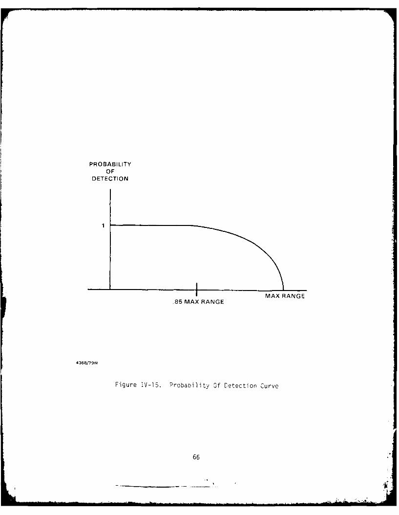
In the event that a target flight and an acquisition unit occupy
the same hex, immediate acquisition is assumed. Otherwise the maximum
detection range for any device associated with the unit is considered.
Figure IV-15 shows the probability of detection curve assumed for all
devices in MADEM; for the region of the curve where detection is effec-
tively a stochastic event (i.e., between 85% and 100% of the maximum
detection range) a single replication MONTE CARLO process is modeled. For
targets which are successfully detected, a test is made on azimuthal scan
limits and detection events are nullified unless the target is located in
the scan sector.
For cases where detection can occur given the above conditions,
terrain masking to the acquisition unit is tested. The line of sight
calculation assumes a curved earth and utilizes a value of 4/3 earth radius
to account for radar propagation effects. Terrain masking angles are
calculated for 25 km hexes along the line uf sight from the detection radar
site to the target; these are compared to the line of sight angle to
determine whether masking exists. For units located in the same 25 km hex,
line of sight is assumed to exist. Figure IV-16 shows a schematic example
of the line of sight calculation.
Detection events in MADEM are essentially instantaneous and are
scheduled to occur at the same time that a flight reaches the hex location
initiating the detection event. In the nonautonomous (CRC) mode of
operation, detections made by BOC's and batteries are passed instan-
taneously to the commanding CRC; BOC's operating autonomously conduct
detection independently and also receive track information instantly from
their subordinate batteries. In fully autonomous operation, all detections
occur at the battery level.
In the CRC mode of control, IFF processing is assumed to occur at
the CRC. For detections made by the CRC, perfect IFF is assumed. Detec-
tions made by the BOC's and batteries are passed to the CRC as hostiles;
65
PRO BA B ILITYOF
DETECTION
1
MAX RANGE85 MAX RANGE
4368/79W
Figure IV-15. Probability Of Detection Curve
66

TARGET
ACQUISITION%-jeOfUNIT
LOCAL PSTO
4%3 MEANEARTH
RADIUS
4368179VV
Figure IV-16. Line-Of-Sight Determination
67

the CRC then detects IFF errors of the type where hostile aircraft have
oeen declared friendly with 90% probability. When operating autonomously,
BOC's and batteries determine the identity of a flight based on a single
replication MONTE CARLO process, with probability of correct identification
equal to 97%. The identity of a flight is determined once for each con-
tinuous engagement of that flight; only flights identified as hostile are
engaged.
4. Threat Allocation
a. CRC Threat Allocation
The CRC threat allocation processes may be triggered by any
of the following events:
(1) CRC detection of a flight movement
(2) CRC detection of a flight death
(3) CRC receipt of a message from a BOC regarding a flight movement
(4) CRC receipt of a message from a BOC regarding a flight death
(5) CRC receipt of a message from an interceptor regarding the death
of a red flight
(6) CRC receipt of a message from an interceptor regarding the avail-
ability of the interceptor.
The CRC first determines the direction of the Red flight. If the Red
flight is returning home, it is marked nonavailable and no further attempts
are made to assign either interceptors or SAM BOC's. If the Red flight is
incoming, the CRC first attempts to assign the enemy flight to one of its
airborne interceptors. If no interceptors are currently airborne, the air
bases under the CRC's command are asked to scramble their available air-
craft. If no aircraft are available the CRC attempts to assign a SAM
battery. If an interception flight is airborne and not already assigned to
a Red penetrator its ability (in terms of operational range) to intercept
the enemy flight is determined. If it can intercept the enemy it is
assigned to do so and the assignment process is terminated. If it cannot
intercept the enemy and no other interceptor flights are airborne, the CRC
attempts to assign a SAM BOC to the penetrator.
68

In attempting to assign a BOC to an incoming Red penetrator,
the CRC considers the distance of the penetrator from the BOC, the altitude
of the penetrator and the saturation limit of the BOC. The CRC checks all
available BOC's to determine their distance from the penetrator. BOC's
greater than 1000 km from the penetrator are dropped from consideration.
The CRC then checks the saturation levels of the remaining candidate BOC's.
BOC's with more than 30 enemy flights already assigned are dropped from
further consideration. The altitude of the penetrator is then considered
to determine the appropriate type of BOC for assignment. Penetrators
flying above 3000 meters are assigned to the first available NIKE-HERCULES
or PATRIOT BOC. Penetrators flying at or below 3000 meters are assigned to
the first available HAWK or PATRIOT BOC. The assigned BOC then initiates
its own penetrator assignment process to determine which of its subordinate
batteries will be assigned to fire on the penetrators. If no BOC assign-
ment can be made, the incoming penetrator is ignored until defensive assets
become available.
b. BOC
Three types of battalion operations centers (BOC) are
treated in MADEM -- Hawk, Nike Hercules, and Patriot. All types are
treated in basically the same way. MADEM modeling for the threat alloca-
tion processes of a BOC is discussed below in terms of the treatment of the
digestion of threat data, the tracking of the status of subordinate bat-
teries, and the decision processes by which particular subordinates are
selected to engage particular threats.
1) Digestion of Threat Data
The threat digestion process for a BOC involves all
processing of threat data relevant to the unit's allocation decisions.
Digestion of threat data is represented in MADEM in terms of cyclical
attention to each member of a particular set of threats (or potential
threats).
a) Basic Representation of Digestion Process
Associated with each BOC is a data structure
called an Active Digested Information List (ADIL). The ADIL includes one
69
element for each threat currently in the set of threats under active con-
sideration. The ADIL is basically a circular list of threats, and a
pointer i:ito the list indicates, at any time, the particular threat for
which information is to be digested next -- i.e., the next threat to which
the BOC is to pay explicit attention. It is upon the occurrence of a
PONDER(DIGEST) event that data on the next threat to be considered is
actually digested. The model assumes that each DIGEST event requires a
certin minimum amount of time (MINTIMEDIGEST). Thus, successive DIGEST
events for a particular BOC must be separated by at least this interval.
The time required to digest information on all threats in the ADIL is then
equal to the product of the number of threats in the ADIL and the minimum
digest time. To prevent this cycle time from getting arbitrarily long, a
limit (MAXNUMDIGESF) is imposed on the number of threats allowed in the
ADIL at any particular time. Once the ADIL is full, additional threats
which would otherwise be considered must be ignored until one of the
threats currently in the ADIL is dropped for some reason. When the ADIL is
not full, the time between successive DIGEST events may be greater than the
minimum referenced above. In general, the model attempts to keep the
digest cycle time at a specified value (MINCYCLEDIGEST). Subject to the
limit imposed by the minimum digest time.
b) Inclusion of Threats in Digestion Cycle
Initially, a particular threat will be inserted
into the ADIL for one of two reasons. If a BOC is under the command of a
CRC, then only threats assigned to the BOC by the CRC will go into the
ADIL. In this case, a threat inserted may not even be initially detectable
by the BOC. The fact that the threat is in the ADIL will, however, enhance
the chances of its detection when such detection becomes possible. For an
assigned threat, the probability that the threat is detected, given it is
potentially detectable, is 1.0. If a BOC is operating autonomously (i.e.,
not under the control of a CRC), then any detection of a threat, or
potential threat, which is not already in the ADIL will result in immediate
insertion of that threat. provided that the ADIL is not full.
70

For a BOC operating under CRC control, it is
possible that more threats may be assigned than can be accommodated simult-
aneously in the ADIL. Threats assigned when the ADIL is full gn into a
Force Out Queue (FOQ) to await the opening of space in the ADIL. When such
an opening arises, the top item on the FOQ is inserted.
A final way in which threats are inserted into the
ADIL involves transfer from another list called the Passive Digested
Information List (PDIL). A threat is moved from the ADIL to the PDIL when
the BOC has allocated the desired level of coverage against it by assigning
it to one or more subordinate batteries. The BOC pays no explicit
attention to threats on the POIL, since responsibility for these threats
has been transferred to subordinates. Should one of these subordinates
report a significant change in the threat, or should one or more of them
report inability to engage the threat, then a resumption of consideration
of the threat by the BOC is indicated. In such a case, an attempt is made
to return the threat from POIL to ADIL. If the ADIL is not full, there is
no problem. If it is full, then the considered threat may go temporarily
to the FOQ, or some low-priority threat currently in the ADIL may be
transferred to the FOQ to make room.
c) Elimination of Threats from Digestion Cycle
A particular threat may be eleminated from the
ADIL for any of a number of reasons, some already referred to. If an
assigned threat is inserted into the ADIL before it is actually detectable
by the BOC (or its subordinates), it will remain there only 120 seconds if
not detected. When an assigned threat is ejected in this fashion, a
message is sent to the CRC rejecting the assignment.
A threat may also be ejected from the ADIL as the
result of a determination that it is not projected to be engageable by any
of the BOC's subordinates. Such ejection by a nonautonomous BOC is again
accompanied by an assignment rejection message to the CRC. A threat so
ejected by an autonomous BOC might well reenter the ADIL upon its next
movement (assuming detection), but in the meantime the ADIL space would be
available for the entry of other possible engageable threats.
71
_______ _____-

A threat once detected but then lost to sight may
also be ejected from the ADIL if not redetected sufficiently soon. At each
DIGEST event, the time of the latest detected information on the considered
threat is compared to the time of the last-digested data. If the two times
differ, then new data is available for digestion; if not, then either the
old data will be retained and the threat checked again on the next digest
cycle, or the threat will be ejected from the ADIL. Ejection is indicated
if the last digested information is older than a specified threshold
(LOSTTIME).
Since an autonomous BOC will insert any detectable
flight into the ADIL if there is room, both RED and BLUE flights may appear
in the list. If digestion of data on a particular threat leads to a con-
clusion that the considered flight is BLUE, then that flight will be con-
sidered non-threatening and will be ejected from the ADIL.
d) Nature of Basic Information Digested
As noted in a previous section, calculations to
determine the detectability of a particular flight are carried out in
connection with PERCEPT events coinciding in time with FLY events for the
flight. The results of each such determination are then assumed to hold
until the time of the flight's next FLY event. Thus, when a particular
flight is considered in a DIGEST event, the outcome of that event depends
on the results of the most recent PERCEPT events involving the flight and
the BOC and its subordinate batteries. When the subject flight of the
DIGEST is detectable, three types of data may be obtained regarding the
flight--its nature as friend or foe, its course, and its size. In the case
of a nonautonomous BOC, all considered flights are assumed to be RED. The
BOC simply goes along with the CRC's prior assessment of the flight as foe.
A BOC operating autonomously, however, must make its own determination.
This determination is not made on every digest event, but only on those
which involve the initial digestion of data on a new ADIL entry. So long
as a flight remains in the ADIL, it retains its original characterization.
Each time a particular threat reenters the ADIL after ejection, its
identity as friend or foe is determined anew. On each such determination,
72

the model assumes a 0.03 probability that an error will occur. Thus, it is
possible that certain BLUE flights may be assigned for engagement, while
certain RED flights are erroneously rejected as targets.
Digested data on the course of a considered flight
reflects the hex position of the flight at the time of its last FLY event,
along with the flight's current heading and speed. Due to the fact that
the flight's movement on the MADEM hex grid only approximate the actual
assumed straight-line flight path legs, the actual projected course
resulting from a digest event may vary somewhat from the actual assumed
course. Any error present, however, appears only as a displacement of the
calculated course from that assumed in a direction perpendicular to the
flight heading. The maximum such displacement is half of a 9.45 km hex
diameter, which is the same as the uncertainty for the ground unit loca-
tions.
The size-of-flight data derived from a DIGEST
event reflects the actual current number of aircraft in the flight.
e) Processing of Basic Digested Information
Since the real purpose of the digestion process is
to support the BOC's allocation decision processes, the basic data on
threat course and size discussed above is transformed into direct inputs
for these processes. These inputs are of three types -- projected
engagement windows, threat priorities, and desired coverage levels.
1. Engagement Windows
During the course of the simulation, lists of
projected engagement windows are maintained for each BOC. Each BOC has an
individual list associated with each flight under consideration, as well as
an individual list associated with each surviving subordinate battery.
Such lists may be created, updated, and destroyed as part of the overall
digestion process. Whenever new threat heading or speed data is digested
for a particular threat, the set of engagement windows implied by this
course data is also determined, and this data goes into a new list of
windows for the considered threat. The data is also used to update window
73
- : q - o

lists for the individual batteries. Any engagement windows based on pre-
vious (now superseded) course data for the considered threat are elimi-
nated.
Individual engagement windows are generated
by calculating times of entry into and exit from the engagement areas of
individual subordinates. For Hawk and Nike Hercules systems, engagement
areas are assumed to be circular. The area for a particular battery is
centered at the battery location and has a specified radius (MISSILERANGE).
For Patriot batteries (firing sections), the engagement area has the shape
of a circular wedge, with the tip of the wedge at the battery location.
The total shape of the wedge is determined by a specified radius (MISSILE-
RANGE), a specified center line (primary target line) orientation, and the
angular width ( 0) of the wedge. In the actual windows opening and
closing calculations, allowance is made for the lead time in firing
required to achieve intercept at the points of entry into and exit from the
engagement area. Thus, the window's limits generated are limits on firing
time, rather than on intercept time. In making the firing time calcula-
tions, the nominal flyout speed of the missile (MISSILERANGE/TIMEFLIGHT) is
employed. A projected window of less than a specified time length
(ENGAGEWINDOW) is treated as no window at all.
The calculation of projected engagement
windows involves no consideration of the altitude of the considered flight.
The CRC considers threat altitude in assigning targets, and the battery
units consider altitude after achieving track on threats, but the BOC does
not consider threat altitude at all.
2. Threat Priority
A BOC assigns priorities to considered
threats on the basis of their headings and the times of the latest pro-
jected opportunities to engage them. The prime determinant is heading.
Three priority categories are defined as follows:
Category 1 - threats with headings 450 or less off
of due west
74

Category 2 threats with headings between 450 and
900 oft due west
Category 3 - all other (eastbound) threats
Within each category, threats are ranked in order of the times of last
engagement opportunity. Those threats for which the opportunity to engage
will pass most quickly are given highest priority.
3. Desired Coverage
On the basis of the number of aircraft
included in a particular flight, a BOC determines the level of coverage
appropriate. Level of coverage is measured in terms of the number of
simultaneous independent engagements to be carried on against the member
aircraft of the flight. Included in the MADEM data base for each BOC type
are desired coverage levels for flights of one (COVONONE), of "few"
(COVONFEW), and of "many" (COVONMANY) aircraft. Also included is the
specified dividing line (FEW) between "few" and "many".
2) Tracking of Subordinate StatusIn situations in which a BOC has the option of
assigning a given threat to any of a number of subordinate batteries, the
decision as to which battery in particular should receive the assignment is
based on the current levels of readiness of the individual batteries and on
the load already imposed on each. A BOC's perception of the status of a
particular battery is based on an initial knowledge of its status, updated
during the course of the simulation on the basis of assignments made to and
messages received from the battery.
a) Initial Status Data
At the outset of the simul "r, ROC knows the
(constant) location of each battery, the total ,umber of rounds of
ammunition, and the maximum number of independent concurrent engagements
which the battery can carry on. While the total number of rounds is known
for each battery, the breakdown of this ammunition by type (conventional,
75

low-yield nuclear, high-yield nuclear) is not known for those system types
where a mix of types is allowed.
b) Updating of Status Data
During the course of the simulation a battery may
send a variety of messages to its superior BOC. Some types carry specific
status information on the battery itself, while others carry information on
the status of a current assignment of the battery.
At the time of each missile firing, a battery
sends a message which indicates the number of rounds expended, and also
indicates any reduction in the number of independent concurrent engagements
the battery can support. For example, if a firing exhausted the ammunition
for one of the two fire units of a Hawk battery, the firing report would
indicate a reduction of one in the engagement capacity of the battery. A
message is also sent to the BOC when new ammunition becomes available to
the battery in connection with a RESUPPLY/RELOAD event. This message is
effectively the inverse of the firing report, in that it indicates rounds
added and engagement capacity added, if any.
With regard to a particular assigned target, a
battery may send messages indicating the effective end of the assignment.
Such messages may indicate either a successful termination, due to
destruction of the target, or an unsuccessful one, due to closing of the
engagement window. In either case, such messages report a lightening of
the current assignment load on the battery. Batteries also report the
destruction of individual aircraft within flights, so that BOC's may
reassess the coverage level appropriate for the diminished flight.
A battery may also send a message to its commander
the effect of which is to cause the BOC to check on a particular target to
determine if its assignment to the reporting battery is still justified.
Such a message is sent when an assigned target is not sighted as expected,
or when it is initially detected but subsequently lost to sight. When an
assigned target is observed to deviate significantly from the course
indicated by the BOC in the original target assignment order, a similar
message is sent. In this case, however, the message is intended more to
76
make the BOC aware of the possibility of new engagement opportunities for
other batteries than to indicate any important change in the status of the
reporting battery itself. In an instance in which the course change was so
dramatic as to preclude the battery from engaging the target, the battery
would simply report a closing of the engagement window.
3) Assignment of threats to batteries
The basic goal of each BOC player in the MADEM simu-
lation is to see that an appropriate level of coverage is maintained on
each considered threat at all times. A BOC achieves this coverage by
assigning the threat to one or more subordinate batteries. Decisions as to
which threats will be assigned to which subordinates, and when, are made on
the basis of the digested threat data and subordinate status information
discussed above. There are three basic situations in which a BOC in MADEM
may make a threat assignment. One of these involves the consideration of a
particular threat which is not sufficiently covered. Another involves the
consideration of a particular subordinate with currently idle engagement
capacity. The third involves the opening of an engagement window involving
a particular threat and battery combination. The nature of the assignment
decision in each situation will be discussed in turn, and instances in
which a battery may be ordered to reduce its coverage of a threat will then
be discussed.
a) Selection of Battery(s) to Cover a Threat
There are a number of circumstances under which a
BOC in MADEM will seek a particular battery, or batteries, to which a
particular considered threat can be assigned. Some of these circumstances
arise in the threat data digestion process, while others arise from the
processing of reports from subordinates.
When a particular threat is initially considered
in the digestion process, and engagement windows are projected as a result,
the BOC will make its initial attempt to cover (assign) the threat. Also,
when digestion of new information on a previously considered threat
indicates a course change resulting in new engagement opportunities, an
attempt to assign new coverage may occur.
77

The above circumstances under which there may be
an attempt to assign a threat relate basically to the realization of new
engagement opportunities. Attempts to assign may also arise out of the
realization of the ends of previously projected opportunities. In such a
case, the spur to the assignment attempt will be a report from some sub-
ordinate to which the considered threat was previously assigned. A sub-
ordinate might, for example, report the closing of its engagement window
against an assigned threat. In such a case, another subordinate must be
sought to replace the lost coverage on the particular threat considered.
Alternatively, a battery might report its total disablement by air-to-
ground attack. In tnis case, alternative coverage must be sought for all
of the threats currently assigned to the disabled subordinate. A battery
might also report a decrease in engagement capacity due to ammunition
expenditure. Such a decrease would imply a decrease in the maximum
allowable load for the battery. In a situation in which the battery's
current load exceeds the new allowable maximum, the load is reduced by
cancelling .one or more of the current assignments. There is then a need to
seek other batteries to which assignments can be made to compensate for the
lost coverage.
A particular battery, or set of batteries, is
selected to engage a considered threat on the basis of the following:
(1) timing of projected engagement windows
(2) current engagement capacities of batteries
(3) current loads on batteries
(4) current ammunition stocks of batteries.
Only batteries for which a projected engagement window against the threat
is currently open, or will open within two minutes, are considered as can-
didates for assignment to the considered threat. Also, only batteries
which do not already have a full assignment load are considered. These
batteries, if any, which satisfy the above criteria are divided among the
following three perference categores:
(1) batteries for which there is adequate response time, and for
which the current engagement capacity exceeds the current
engagement load
78

(2) batteries for which there is adequate response time, but for
which current engagement capacity does not exceed the current
engagemenL load
(3) batteries for which there is minimal time to respond, and for
which the current engagement capacity exceeds the current
engagement load
Response time adequacy is determined by the closing time of the relevant
engagement window. If the time between the assignment decision and the
projected closing of the window does not exceed a specified threshold
(LOWRESPTIME), the likelihood that the battery involved could successfully
respond to an assignment order is assumed to be low. Thus, preference is
given to assignments where the projected time to respond is adequate. A
secondary preference is given to batteries which can immediately undertake
engagement could be supported concurrently with those against any already
assigned targets. It may be noted that the above listed preference
categories do not cover all assignment candidates as defined above. Those
for which there is minimal response time and for which the battery could
not support another independent engagement immediately are eliminated from
consideration.
Within each of the three general preference categories
defined above, individual batteries are ranked in order of ammunition
available minus engagement load. Batteries are selected for assignment in
accordance with the indicated preference order until the desired level of
coverage has been achieved against the considered threat, or until all
currently possible assignments of the threat have been made. A particular
battery selected to engage the threat may be assigned to provide more than
one unit of coverage (independent engagement) on the threat. Such coverage
will be ordered if called for by the size of the threat and made possible
by the engagement capacity of the battery.
b) Selection of Threat(s) to be Covered by a Battery
A perceived change in the status of a particular sub-
ordinate may give a BOC reason to seek some new assignment(s) for that
subordinate. For example, a report from a battery indicating the activa-
tion of new engagement capacity due to ammunition resupply will occasion
79

such a search. Similarly, a reduction of the load on a battery may be
reason to seek new assignments to make maximal use of the battery. Such a
load reduction may result from the end of a previous engagement, or from a
reduction in the assigned coverage level against some threat.
When assignments are to be sought for a particular
threat, only those threats which are in the BOC's active digested infor-
mation list and which do not have the desired level of coverage assigned
are considered. Such threats for which the considered battery has open, or
soon to open, projected engagement windows are split between two preference
categories:
(1) threats for which the battery has adequate projected response
time
(2) threats for which the battery has minimal projected response
time.
Again, response time adequacy is based on the time to the projected window
closing for the threat; if this time exceeds a threshold (LOWRESPTIME),
there is assumed to be adequate time for the battery to respond to an
engagement order. Within each category, individual threats are ranked in
order of their assigned priorities. Tracks are selected for assignment to
the battery, in accordance with the discussed preference order, until the
battery is fully loaded, or until all allowed assignments have Deen made.
If a threat is selected for which the ci~rrent coverage shortfall is greater
than one, then the battery may be assigned more than one unit of coverage
on the threat, assuming that it is capable of simultaneous, independent
engagement of members of the threat flight.
c) Consideration of Projected Window Openings
As indicated previously, a BOC in MADEM will not
assign a threat to ittery more than two minutes in advance of the pro-
jected opening of the relevant engagement window. Thus, some projected
engagement windows cannot be used as bases for assignment decisions until
some time has passed after their generation by the process of threat aata
digestion. When a window i5 projected which cannot be used immediately, an
event is scheduled to occur in the simulation at the time at which the BOC
80

could first make an assignment decision on the basis of the projection.
The occurrence of this event (called an OPPORTUNITY KNOCKS event) causes
the BOC to consider assigning the threat involved to the battery involved.
Such an assignment will occur if the threat is not already fully covered,
and the battery is not already fully loaded.
d) Reduction in Battery Assignments
A BOC may decide to reduce the assignment load of
a battery for either of two basic reasons. The first of these reasons is a
decrease in perceived size of an assigned threat. A BOC may become aware
of attrition of a flight either through its own digestion process or
through reports from its subordinates. When a change is noted which
implies a change in the level of coverage appropriate for the threat (i.e.,
a change from "many" to "few" or a change from "few" to one), the BOC can
reduce the coverage by cancelling an assignment, or by reducing the
coverage level associated with a particular assignment. When a choice is
to be made regarding which battery should have its load reduced in con-
nection with a coverage reduction, the candidate with the least ammunition
surplus (ammunition stock minus load) is selected.
The second reason for reducing the assignment load
on a battery is a decrease in the engagement capacity of the battery.
Since the maximum allowable load for a battery is calculated as a multiple
(MAXASSIGN) of the current engagement capacity, a decrease in this capacity
may leave the battery overloaded. In such an instance, the BOC relieves
the battery of some of its assignments. Assignments are cancelled, as
necessary, in reverse order of the priorities of the threats involved.
c. Battery
Three types of SAM batteries are treated in MADEM -- Hawk,
Nike Hercules, and Patriot. Many aspects of the modeling of threat allo-
cation processes in MADEM are common for all three battery types. The
major differences among modeling for the three relates to the treatment of
engagement capacity for a battery. A Hawk battery is treated as two
distinct fire units. Each fire unit has its own ammunition supply, and the
two fire units can engage separate targets independently. When a fire unit
81

runs out of ammunition, the engagement capacity of the battery is decreased
by one. A Nike Hercules battery is treated as a single fire unit; thus,
the engagement capacity of such a unit is always one, so long as ammunition
remains. A Patriot battery player, which actually more nearly represents a
Patriot firing section, is treated as a single unit with a capacity for
multiple simultaneous independent engagements, all of which draw upon the
common ammunition supply associated with the unit. The maximum number of
simultaneous engagements allowed to such a unit is subject to the con-
straint that there must be at least one missile committed to each engage-
ment in progress at any given time.
The discussion of the threat allocation process for
batteries which follows will be similar in form to the previous discussion
of such processes for BOC's. Digestion of threat data will be treated
first. The tracking of fire unit (engagement capacity) status will then be
touched upon. Finally, the decision processes by which particular threats
are selected for engagement by particular fire units will be discussed.
The threat digestion process for a battery in MADEM involves
all processing of threat data relevant to the unit's engagement decisions.
The basic nature of the digestion process is identical to that discussed
earlier in connection with BOC's.
The battery maintains an Active Digested Information List
(ADIL) equivalent to that maintained by a BOC. For a nonautonomous
battery, only threats assigned by the commanding BOC are entered in the
ADIL for processing. For an autonomous battery, all detectable threats go
into the ADIL, so long as the ADIL is not filled to capacity. Each battery
also has a Force Out Queue (FOQ) which serves the same function as for a
BOGC. A battery does not have a Passive Digested Information List (PDIL),
since a battery has no subordinates to which it can pass off threats. Each
battery does, however have a corresponding structure called the tracked
list. Threats are moved to this list from the ADIL when tracking of the
threat is initiated as part of an actual engagement. Threats on the
tracked list are effectively under continuous scrutiny. New information is
digested on such a threat immediately each time it moves; there is no wait
for the threat to be reached in the normal cycle through the ADIL.
82

A significant difference between ADIL entries for BOC's and
batteries is that assigned threats have associated course data when
initially added to the ADIL by batteries. This data is passed to the
battery by the BOC. No such data is passed from CRC to BOC. After a bat-
tery initially digests data on an assigned threat, it can detect any course
change which has taken place since the BOC's last digestion of data on the
threat prior to its decision to assign. This allows the battery to report
such changes to the BOC, so that the BOC might reassess its previous deci-
sions.
The particular threat data digested by batteries -- flight"side", course, and size -- is identical to that for BOC's. Like BOC's,
batteries assume assigned threats to be RED. Confusion of the loyality of
unassigned threats is handled similarly.
For an autonomous battery, the basic outputs of the diges-
tion process are the same as for BOC's -- engagement windows, threat
priorities, and desired coverage levels. For a battery under command of a
BOC, however, the desired coverage level for each threat is specified by
the assignment order. This level can be changed only by further orders
from the BOC.
A battery calculates engagement windows for itself in the
same manner as a BOC does for each of its subordinates. Should a battery's
window determination indicate that no window for an assigned threat --
perhaps due to course change, or to insufficient response time -- the
battery will report a window closing to its BOC and give up on the assign-
ment.
A non-autonomous battery assigns priorities to threats in
the same manner as does a BOC, on the basis of heading and last opportunity
(of the considered battery only) to engage. Priority assignment by
autonomous batteries is basically similar, but differs in the precise
manner in which threat heading is treated. Instead of assigning highest
priority to threats whose headings are within 450 of due west, an auto-
nomous battery gives top priority to threats with headings within 45o of a
direction specified for the individual unit. Each battery has a Primary
83

Target Line (PTL) defined in terms of a heading from the units position.
Flights approaching from the direction of the primary target line are given
top priority. Second and third priority categories are defined as before,
but with the role of due-west being taken by the heading PTL+I800.
For autonomous batteries, the determination of the coverage
level appropriate for a threat is carried out just as for a BOC. The
coverage levels appropriate for one, few, and many may be different, how-
ever, from those accessed by the BOC, since the data used by the battery is
accessed from a battery type data base instead of from the BOC type data
base. The battery type data base should not indicate, for any size flight,
a desired coverage greater than the maximum engagement capacity of the
battery.
The basic goal of each battery player in the MADEM simula-
tion is to see that an appropriate level of coverage is maintained on each
considered threat at all times. A battery seeks to achiove this goal by
allocating appropriate firepower against each threat. In the case of a
Nike Hercules battery, there is not question of which firepower should be
allocated, since there is only one fire unit available. The case of a
Patriot battery is basically similar, in that all firepower is assumed to
be allocated from a single common pool. In the case of a Hawk battery,
however, two fire units are represented as distinct entities. A separate
ammunition stock is tracked for each, and there is, thus, a basis for
selecting a particular fire unit for a given engagement.
Decisions resulting in the allocation of firepower to par-
ticular threats are made in two basic situations. One of these involves
the consideration of a particular threat which is not adequately covered.
The other involves the consideration of newly idle firepower.
A battery may decide to allocate firepower against a threat
at the time at which the threat is initially considered in the digestion
process. This will happen if an engagement window of significant length is
projected and idle firepower is available. Also, firepower may be
allocated against a threat as the result of new window projections
generated during subsequent treatments of the threat in the digestion
84

process. Firepower is to be allocated in order of available ammunition, in
order to keep both fire units operational for as long as possible.
Whenever new firepower becomes available, a battery will
seek a threat (or threats) to occupy that firepower. New firepower may
become available as the result of an engagement ending, or as the result of
a RESUPPLY/RELOAD event for the battery. Threats for engagement are chosen
from among those with currently projected engagement windows, in accordance
with threat priority.
Just as BOC's may decide that subordinate batteries should
reduce coverage levels on certain threats, so also may autonomous batteries
decide to reduce coverage. Thus, for example, an autonomous Hawk battery
might start out engaging a flight of "few" aircraft with both fire units,
but continue the engagement with just one fire unit when the target had
been attrited to just one aircraft. When a Hawk battery does engage a
single flight with both fire units, it will cease fire first with the fire
unit with less ammunition.
d. Interceptors
Interceptors are normally vectored to intercept incoming
penetrator flights by their commanding CRC. However, interceptors will
also engage penetrators which pass within one hex (9.45 km) of their flight
paths. After each engagement, surviving interceptor flights request orders
from their CRC. If the CRC is still alive and able to communicate, inter-
ceptors with sufficient fuel remaining will be assigned to new target
penetrators. Interceptors with insufficient fuel will return to their
respective airbases.
When an interceptor's commanding CRC has been destroyed or
cannot communicate, the interceptor returns to its airbase and assumes a
CAP orbit until it must land for refueling. Any penetrators encountered on
the return flight will be engaged by the interceptor if its fuel level
allows. If it has insufficient fuel it will attempt to disengage and
retreat to its air base.
85
e. Air Bases
Under normal conditions blue airbases launch interceptors
only in response to orders from their commanding CRC. However, if their
CRC is destroyed air bases will launch interceptors to fly defensive CAP
orbits. These interceptors will defend the air bases by engaging any
penetrators which close to within on hex (9.45 km) of the base.
5. Engagements
a. Air-Air Engagement
Air-air engagements in MADEM are treated in terms of salvo
exchanges of user defined ordnance packages between flights of aircraft
located in the same or adjacent hexes. Interceptors, fighters or fighter-
bombers with a designated air-air capability all can engage airborne tar-
gets; up to 10 separate air-air ordnance types can be allocated to each
generic air-air flight.
Target acquisition for air-air combat can occur in three
ways. First, a hostile flight may move into the same hex or a hex adjacent
to the one currently occupied by a flight. Second, a flight may move into
a hex and perceive a hostile flight in the same or an adjacent hex.
(Identification/ Friend or Foe is assumed to be perfect for airborne
systems, i.e., visual identification before engagement is assumed.)
Finally a flight may perceive that it is under attack by a hostile air-
craft. After acquiring a hostile flight, an evaluation is made of the
capability to carry out a successful attack.
Assuming that a flight is not actively engaging a target, it
will engage any hostile flights encountered as long as air-air ordnance of
any type and fuel remain ava~lable. An 11 second "reaction time" delay
occurs between detection of a hostile flight and launching of ordnance.
During this period, the attacking flight goes to aircombat speed; if the
flight is an interceptor flight and if the detected hostile flight is not
the target originally assigned by the CRC, a message is sent to the CRC
indicating that a target of opportunity is being attacked. If the flight
initiating the attack is a fighter-bomber flight, all air-ground ordnance
is jettisoned before launching air-air ordnance.
86

The actual engagement process model for air-air combat
consists of choosing an ordnance package from the remaining air-air
ordnance remaining for the attacking flight; launching a salvo; and damage
assessment. Ordnance packages are user defined weapons groupings to be
launched simultaneously by each aircraft, e.g., 1 AIM-7 missile, 2 AIM-9
missiles, half second air-air gun bursts, etc. Ordnance packages are
developed independently for each aircraft type, and thus are intended to
reflect the ordnance compatibility of alternate aircraft, as well as
expected tactics and firing doctrine. Ordnance packages are chosen based
on a fixed priority developed for each aircraft type; lower priority
packages are not employed until all higher priority packages have been
expended.
After the applicable ordnance package has been chosen, each
aircraft in the attacking flight fires its ordnance package; total salvo
size is thus dependent on tht attacking flight size, as shown in the
figure. Available ordnance for the flight is updated to reflect the
expenditure of salvos independently for each flight.
All ordnance in a salvo is assumed to be launched simul-
taneously; attrition is based on a sequential, independent MONTE CARLO
process employing user developed probability of kill (Pk) values for each
ordnance package against a single aircraft. Currently, Pk values do not
reflect alternate vulnerabilities for different aircraft types, dynamic
degradation of weapon effectiveness of ECM, or changes in Pk as a function
of differences in target vs. firing flight range and altitude. One MONTE
CARLO replication is made for each ordnance package launched in a salvo,
due to the large number of total engagements expected for typical model
cases.
The primary result of the assumptions discussed above is
that attacking aircraft do not engage target flights independently but
sequentially, with the exception that an entire salvo is always expended,
even if no targets remain for the final ordnance packages. For example, if
a flight of four interceptors engages a flight composed of a single
fighter, four ordnance packages are always launched, even for cases where
87
.._ _1- -

the nominal first, second, or third packages kill the aircraft. Damage
assessment and kill removal is immediate in the model; no partial damage is
considered. In the event that an interceptor entirely destroys its target
flight, it sends a message to its commanding CRC (if the CRC is alive)
indicating target destruction and availability for assignment to a new
target. Penetrating flights which destroy their targets continue to their
assigned targets from their present position unless they have expended all
of their air-air munitions. Any flight which has expended all of its
air-air munitions or has exhausted its combat fuel returns to its home
air base.
After a salvo has been launched and the damage assessed,
available ordnance for the attacking flight is updated. Three seconds
after ordnance is launched, the flight under attack perceives that it has
been attacked; survivors of the salvo have an opportunity to react.
Flights with an air-air capability, remaining air-air ordnance and
remaining fuel for air combat will respond to an attack by scheduling a
counter attack, after an 11 second delay. Fighter-bombers without air-air
capability, bombers, and any aircraft flight returning to its home airbase
because of fuel or air-air ammunition depletion do not react to air
attacks.
Once an air-air engagement is initiated, it continues until
one of the following events occurs:
(1) The targeted flight evades the attacker;
(2) The targeted flight is destroyed;
(3) The attacking flight is destroyed;
(4) The attacking flight depletes its fuel or air-air ordnance and
breaks off.
The major driver is a continuing engagement in movement of
the flights. Scheduling of movement is based on flight speed and is
independent of scheduling for aircombat events; thus, for example, a faster
aircraft flight can rapidly evade a slower attacking flight. However,
scheduling of aircombat events is coupled to movement; an attacking flight
can fire only one salvo at a target flight unless it moves or fires a
88

retaliatory salvo. This feature is intended to prevent unconstrained
firing of multiple salvos at low speed flights. In the event that an
interceptor flight destroys its target or expends all of its fuel/air-air
ordnance, it sends a status message to its commanding CRC. In the event
the interceptor flight is destroyed, the CRC is immediately aware of the
loss.
Offensive fighters and fighter-bomber flights engage only
Qir-air targets of opportunity (i.e., interceptor flights) encountered
while ingressing or egressing from their assigned targets. No attempt is
made to portray offensive, hostile air superiority missions by the threat.
Interceptor flights operate under two modes of control, the
CRC mode and autonomous mode. In the CRC mode, specific target flights
are identified by the CRC, an attempt is made to assign airborne inter-
ceptor flights to these targets. The unassigned interceptor flight which
is closest to the targct and which has an intercept capability is assigned
to the target. Only one interceptor flight is assigned against each target
flight; no consideration is given to actual size of either interceptor or
target flights. Since CRC's have imperfect IFF, the target flight may turn
out to be friendly; in this event, the interceptor flight sends a message
to the CRC indicating a friendly intercept/non-engagement, as discussed
previously.
In the event that interceptors cannot be assigned (either
because all airborne interceptors are assigned or because unassigned
airborne interceptor flights cannot achieve or intercept) then an attempt
will be made to assign ground-air assets against the target. A concurrent
request will be made by the CRC to its subordinate air bases to launch
available interceptors. Currently, CRC's hold their subordinate inter-
ceptor assets autonomously.
Intercept calculations are based on the low of cosines,
assuminq that the CRC has instantaneous heading and velocity (track)
information at the time an intercept assignment is made, and also assuming
that the target flight will maintain its heading and speed. The required
condition is that the time to intercept equal the flight time of the target
89

to the intercept point; this results in the equation derived in the figure.
Once an interceptor flight has been assigned to a target by the CRC, a
continuous recalculation is made of the intercept point, and the inter-
ceptor flies to the intercept point continuously. The intercept assignment
is dropped if intercept fails to remain feasible.
Interceptors may engage targets of opportunity whenever they
are encountered, either in the course of an intercept assignment before the
intercept is made or while on orbit. In the autonomous mode, i.e., when
the CRC is destroyed, all air-air engagements are against targets of
opportunity which encounter interceptors on air patrol orbits near air
bases.
b. Surface to Air Engagements
After an initial 30 second sighting delay for a new track, a
CRC attempts to assign either interceptors or ground-air assets against the
track. Details of the interceptor assignment process are discussed in the
paragraph on air-air processes. When interceptors are not available for
assignment, all BOC's with a nominal capability to see the current location
of the target flight are searched. lhe primary criteria for assignment of
a BOC to a track are:
(1) availability of the BOC to accept the assignment;
(2) range of the BOC to the target -- the closest available BOC is
assigned;
(3) availability to the BOC's of batteries with an engagement cap-
ability at the altitude of the targets, i.e., only NIKE HERCULES
BOC's are assigned to high altitude targets, and only HAWK BOC's
are assigned to low altitude targets.
If a BOC is currently processing less than 30 tracks and is
able to accept an assignment, the BOC processes the track; otherwise a
message is sent to the CRC indicating that the BOC is not ready. In the
event that actual line of sight does not exist to the target (due to
stochastic detection events or terrain masking) the track is tagged as
early warning information and an expected detection event is scheduled.
90

Tracking events are driven by flight movements in much t~ie
same way as detections. CRC's continue to track flights as it perceive"
each flight movement. Track data available to the CRC includes l3tes*
track update time; true flight heading in cartesion coordinates (i.e., -ut
between low level hexes); true flight velocity and true flight altituut
At each track update, the CRC reviews the track assignment status. K'
targets which are viable (i.e., not east bound) and which are assigneI V
interceptors, new interception projections are made and messages sent tC
the assigned interceptor flight. There are no limitations to the track
processing capacity of the CRC.
For tracks detected and perceived to be hostile by an auto-
nomous BOC, or assigned by a CRC to a subordinate BOC, the BOC calculates 3
projected engagement window for each of its subordinate batteries against
the track. Those batteries where an engagement window exists are put on a
list for possible assignment against the track, and a priority is cal-
culated for the track by the BOC. The track is then entered into a
prioritized list of active tracks being processed by the BOC.
As each track is taken from the prioritized list, the list
of batteries with a potential engagement window against. the track is
surveyed to determine which battery has the latest engagement opportunity,
in order to determine when the last chance for engagement of the track by
the BOC occurs. Batteries are assigned against the track in decreasing
order of their associated ready ammunition until a user specified desired
coverage level against the track has been met; the number of batteries
required is in turn based on the actual number of ready fire units and
available ammunition for each battery.
Currently only immediate (i.e., instantaneous) processing is
played in MADEM; however the option exists of representing BOC and battery
processing in terms of a single server queue with user specified processing
times. This option has not been exercised to date. In the autonomous
mode, the BOC assigns all of its resources to the highest priority tracks;
if additional tracks are present, they penetrate without being engaged by
the BOC.
91

For tracks detected by an autonomous battery, or assigned to
a subordinate battery by a commanding BOC, the battery calculates an
engagement window for the track. If an engagement window exists and it
does not exceed a user specified threshold response time (i.e. , a minimum
required engagement window) the track is dropped. Otherwise, the battery
places the track in a prioritized list of all active tracks which it is
considering. It then assesses whether the assigned target can be tracked,
considering existence of line of sight, and maximum tracking range for the
battery, if any. For cases where tracking cannot occur, the target is
dropped; otherwise the battery attempts to assign ready, available fire
units against the track. For NIKE HERCULES and HAWK units, with capabilty
for engagement of a single track at a time, fire units are allocated until
user specified desired coverage against the track is achieved or until all
resources are assigned. For systems such as Patriot, with capability for
multiple simultaneous engagements, a running total of simultaneous
engagement assignments is kept for the battery; engagements are assigned
against a track until user specified desired coverage for the track is
achieved or until all engagement capability is in use.
The basic processes discussed above proceed in parallel at
the CRC, BOC and battery level as tracking of a target continues. As the
target moves and changes direction, allocation of assets is shifted to
reflect the changing conditions as a function of all of the other tracks in
the region.
At each step of the tracking process - i.e., every time a
target flight moves -- batteries tracking the target evaluate their
engagement opportunity.
In considerinn an engagement attempt against a track, a
battery evaluates the current target altitude, which is assumed to be
available as part of the track data (i.e., height finding processes are not
modeled). If the target altitude is not within user specified engagement
limits, the engagement attempt is halted.
For cases where an engagement is possible, warhead types are
chosen to be launched. Three generic systems are currently considered in
92

MADEM, representing HAWK, NIKE HERCULES and Patriot. HAWK fires only
conventional ordnance; thus the only requirement is availability of ready
ammunition. Nikf Hercules is assumed to be able to utilize both "large"
and "small" yield nuclear warheads and conventional warheads. The decision
tree for munition choice is shown in figures IV-17 and IV-18. The user
controls the total pool of munitions to be considered -- i.e., for a con-
ventional only case, no nuclear munitions are specified in the initiali-
zation data. Patriot is assumed to have a capability to utilize both
conventional and "small" yield nuclear warheads; the figure shows the
decision tree for munition use by Patriot units. In the event that no
appropriate munition is available, engagement is terminated.
Where engagement processing continues, the feasibility of an
intercept is calculated. This involves calculating the projected intercept
point, if one exists, and insuring that all engagements take place within
the azimuth and range limits of the engagement envelope of the generic
system. Where intercept is feasible, an intercept time is calculated and
battery firing processes are scheduled.
Two fire doctrines are considered, shoot-look-shoot and
shoot-shoot look. Currently, Nike Hercules and Patriot utilize shoot-
look-shoot doctrines against all targets; HAWK units utilize shoot-shoot-
look doctrine until the fire unit engaging the target has less than 2 ready
missiles or the battery as a whole has less than 9 missles. HAWK then
transitions to the shoot-look-shoot doctrine. Total ammunition status is
updated at both the fire unit and battery level after each firing.
Attrition processes are based on a single replication Monte
Carlo process, using user specified P k functions parameterized on range
from battery to target for each of the ordnance/system type combinations.
Each missile launch is assumed to be independent and one aircraft kill per
missile at most is assumed, i.e., no multiple hit/kill per burst phenomena
are considered. Instantaneous kill removal occurs in MADEM; i.e., Pk data
are assumed to be for K=KILL criteria.
For cases where nuclear warheads are utilized, prompt com-
munications blackout effects are treated. Communications are cut off or
93

AD-AI07 915 SDM CORP MCLEAN VA F/B 15/3MODULAR AIR DEFENSE FFCTIVENESS MODEL, PROGRAM DOCUMENTATION --ETC(U)JAN 80 M FILTEAU, B MACALEER, J T HAWKINS DNAO01"?9-C-0203
UNCLASSIFIED BOM/W-79-646-TR-VOL-1 DNA-5594F-I ML3EllEEEEEEI
llflflflflflflflflflfllEEIIIEIIEEIIEE*lllulumlullluEEEEEEIIIIIIIEEEEEEEllEElhlEEhEEEEEEEuiumnI

LARGE YIELDAVAILABLE USELDRGE
TGT FLIGHT
>5AC
LARGE YIELD USE SMALLNOT AVAILABLE YIELD
/ \ SMALL YIELD
TGT ALTITUDE AVAILABLE USE SMALL
> 600 M GT FIGHTYIELD
L ' VYIELD I , USESMAL YIEL UCONVENTIONAL
NOT AVAILABLE IF AVAILABLETGT ALTITUDE / SMALL YIELD USSML
> 1800 MUSE SMALLAVAILABLE YIELD
/ .......... TGT FLIGHT/ G ALTITUDEy: > s AC ...,- _ USE< 00 MSMALL YIELD CONVENTIONAL
NUCLEAR NOT AVAILABLE IF AVAILABLE
AVAILABLE CONVENTIONAL USET G T
ALFUDE USEICONVIENTIONAL TGTF TAVAILABLE CONVENTIONAL
CONVENTIONAL USE SMALLNOT AVAILABLE YIELD IFNOT AVAVAILABLE
NUCLEAR
MISSILES NOT USE CONVENTIONALAVAILABLE IF AVAILABLE
4368179w
Figure IV-17. NIKE-HERCULES Ordnance Selection
94

USE NUCLEARMISSILETARGET FLIGHTMISL
TARGET ALTITUDE
5 TARGET FLT USE CONVENTIONAL
MISSILE IF AVAILABLE
NUCLEAR MISSILE
AVAILABLETGT ALTITUDE USE CONVENTIONAL
< 1800M MISSILE IF AVAILABLE
NUCLEARMISSILE
NOT AVAILABLE USE CONVENTIONAL
MISSILE IF AVAILABLE
4368179W
Figure IV-18. PATRIOT Ordnance Selection Decision Tree
95

all players located in the same 9.45 km hex as a nuclear burst or inadjacent hexes. For CRC's which are affected, all subordinates (BOC's,
interceptors and air bases) go autonomous. For affected BOC's subordinate
batteries go autonomous. All interceptors in the affected region go auto-
nomous. Currently no reconstitution capability exists for C3 processes,
i.e., units which go autonomous remain autonomous thereafter. No other
degradation of unit effectiveness due to nuclear effects are considered,
and no unintentional fasticide of friendly flights is played.
HAWK, Nike Hercules and Patriot units all assess engagement
outcomes immediately. The engagement will continue until the battery has
expended all of its ammunition, the battery has been killed, the target
flight is completely destroyed, or the target flight is out of range.
Coverage against the track, however, may be altered to reflect attrition as
well as changes in the track priority.
Attrition of flights due to ground based defenses is also
exacted by short range air defenses (SHORADS). However, SHORAD players are
aggregated in MADEM, rather than being explicitly represented, and attri-
tion processes are coupled to flight movement. As each flight moves across
a hex in friendly territory, a Pk for SHORAD systems is determined as a
function of the flight's altitude, i.e.,
Pk = [.Ol/Ln (Altitude)].
A single replication Monte Carlo process is then utilized to
model a single, independent shot by SHORADS systems against each of the
aircraft in the flight. IFF processes are also considered for SHORADS,
since friendly aircraft are effectively recognized as friendly 90% of the
time. However, hostile aircraft are not identified as friendly. Removal
of kills is immediate, and flights may be totally destroyed by SHORADS as
fo,- other weapon systems.
c. Air-Surface Processes
Air-surface processes in MADEM consist of execution of
attacks by flights of hostile fighter bombers and bombers against all
friendly surface players and entities. Surface based, friendly players,
96

N
00
3150lox 10 6 PRIORITY 8x 10⁶
10 X
106450
PRIORITY 5 x 10⁶
2700 90,
10 x 106
PRIORITY 5 x 10⁶ -TLAST
2250 1lx 10, PR 10R ITY
8 x 10Q6
1800
4368p79W
Figure IV-19. Directional Engagement Priorities
97

including CRC's, BOC's and batteries, are all at risk of being killed by
hostile attacks; however, damage from multiple attacks is not accumulated
for these players. Damage is accumlated for friendly air bases; however,
no degradation of airbase operations due to damage is considered. All
other entities in MADEM act as sinks for hostile attacks, with alternative
priorities for the Red Planner; damage is accumulated for these targets
based on the number of attacks made against them and the ordnance loads of
the attacking flights.
As part of the attack planning process, each flight of
hostile fighter bombers and bombers is provided with a planned route to its
target and the hex location of its target. Flights which successfully
reach the target hex attempt to acquire their target. Detection is prob-
abilistic based on a single replication Monte Carlo process for each air-
craft in the flight, using input probability of detection values for the
target. In the event that the target is not detected, the attack is
aborted and the flight returns to its air base. No unassigned surface
targets of opportunity are detected or attacked. If the target is
successfully detected, an attack is scheduled; no delay times from
detection to attack are considered.
The attack process considers attrition due to terminal area
short range defenses using the same algorithm as discussed in the section
on surface-air processors. Surviving aircraft deliver all of their
ordnance on the target; up to 11 alternate types of ordnance can be
treated, including 10 alternate conventional types of ordnance and 1
nuclear type of ordnance.
98

SECTION V
MADEM OPERATION
A. INTRODUCTION
The purpose of this chapter is to explain the operation of MADEM.
Additional information on MADEM operations, including job control language
files, may be found in Appendices D and E of this manual and in Appendix A
of the MADEM Programmer Manual.
MADEM is currently configured for operation on the Air Force Weapons
Laboratory (AFWL) computer system. Since many aspects of MADEM operation
(including the three processor configuration discussed in the following
section) are direct results of AFWL system requirements, the user should
pay particular attention to Appendix D before attempting to run MADEM. The
user should also be aware that MADEM can be reconfigured to run on other
CDC systems with minimal modification.
8. SOFTWARE COMPONENTS
MADEM has three major software components -- a preprocessor, a main
processor, and a postprocessor. The overall configuration of these pro-
cessors and their input and output files is illustrated in FigureV-l.
The preprocessor (sometimes referred to as INITBIN) reads user inputs,
which include the data base and Red Threat planning specifications, and
carries out che Red Threat planning process. The resulting Red Attack plan
is then saved on a "HOLD FILE" for subsequent use by the main processor.
In addition to the "HOLD FILES" the preprocessor also outputs a printed
summary of the Red Attack plar. and a "HISTORY FILE". The HISTORY FILE
contains a record of unit creation events which can be used by the post-
processor to construct summary tables of the types of units created.
The main processor (sometimes referred to as RUNBIN) is used to simu-
late the actual combat processes which result frcn the Red attack. The
main processor is run in a cyclical fashioni. The initial main processor
99

REEEATEOPTIOOR ASANMANY
PREUAE PROCSSO
Y II
43H8/79W
FigureV-i. ADEM rocesor Cofgrto
DATA BSE FI0

run is made using the Red Attack Plan HOLD FILE as input. Combat processes
are then carried out for approximately one hour of game time after which
execution is terminated and HOLD FILES are created containing the status of
all units at the end of the hour. This HOLD FILE then becomes the input
for the next main processor cycle. Each of these main processor cycles is
referred to as a volume. As many volumes can be run as are required to
simulate the desired duration of conflict. The main processor also outputs
an event trace and a history file. The event trace records all of combat
events which occurred during the volume. The HISTORY FILE contains a
record of key events which can be used by the postprocessor to summarize
the battle.
The postprocessor (sometimes refered to as HISTBIN) reads HISTORY
FILES output by the preprocessor and main processor and outputs a variety
of tabular summaries of the battle. These outputs include the following:
e Red aircraft acquired by Blue defense units
a Red aircraft engaged by Blue defense units
* Red aircraft damaged by Blue defense units
* Blue units damaged by Red aircraft
0 Weapon system expenditures by unit type
0 Number of Red aircraft to reach targets
* Number of units created by type.
C. PREPROCESSOR (INITBIN)
MADEM's preprocessor (INITBIN) requires three primary inputs to carry
out Red threat planning: a set of Run Parameter Cards, a Data Base File
and a User Input Language File. Each of these required inputs is described
in detail in the following sections.
1. Run Parameter Cards
The Run Parameter Cards control the preprocessor run. There are
two card types. The first is mandatory. The second is optional. The
formats of these cards are listed below:
101

CARD 1: (UNFORMATTED, MANDATORY)
PARM 1 - Must be Integer 1 for INITBIN
PARM 2 - INTEGER, SIZE OF ISPACE (MAX) during INITBIN (50000)
PARM 3 - Max number of players on either side
PARM 4 - Dummy Value (25)
PARM 5 - Dummy value (999999)
PARM 6 - Dummy value (1)
CARD 2 TO THE LAST CARD:
The second set of options are all optional. Each of these parameters
must begin in column 1. There may be only 1 Parm Per card, with
as many cards, as are necessary. It is recommended that these
options be used only when debugging.
PARMS:
DEBUG=ON' Turns on full debug mode
'DUMP=ON' Will dump ISPACE at end of run.
'DATFLE=ON' - Turns on display Qf QATFILE data structure.
'STOP=ODAT' - Stop INITBIN after DATFILE
'STOP=UOIL' - Stops INITBIN after SEMANT (UOIL)
'STOP=DEL' Stop INITBIN after DELADD, before executing
plan event.
'RECOVR=OFF' - Turns off system recovery routine
EXAMPLE:
1,500000,600,25, 999999, 1
DEBUG=ON
DUMP=ON
DATFILE=ON
STOP=ODAT
2. Data Base File (DATFILE)
The Data Base File contains basic specifications for all of the
player units in MADEM as well as probability of kill and probability of
detection tables. It consists of a scenario title card and a series of
102

data class code cards along with their associated specification cards. The
number and format of the specification cards will vary with class code.
The first card in the Data Base File must be a Scenario Title
Card. This card may contain an up to 70 character description of the
scenario to which the data base applies. This description will become the
header for the preprocessor printed output.
The Title Card is followed by a series of 13 classes cf data.
Each class consists of a Class Code Card followed by a series of Specifi-
cation Cards. The data classes must be inserted in the following order:
CLASS CODE DESCRIPTION
(1) 6026 Air Defense Site Data Base
(2) 6006 Unit acquisition range information
(3) 6004 Payload data base
(4) 6003 Aircraft data base
(5) 6005 Flight profiles
(6) 6002 Flight specifications
(7) 6001 Formation specifications
(8) 6007 Air base queue specifications
(9) 6008 Initial assignment of aircraft to
air bases.
(10) 6101 Air to air probability of kill
(11) 6102 Air to ground probability of kill
(12) 6103 SAM probability of kill
(13) 6201 Air-to-air probability of death
Each class of data will be shown separately to define the varying
input formats for each. Basically, all classes will consist of one class
code card followed by specification cards that are unique to each class.
The forma,. for each card is defined below. On all cards, each field is
separated by a comma. Fields which are labeled model value are non-user
specified but are required for proper operation of the model.
103

CLASS 6026
Air Defense Site Data Base
Class Code Card
Field Title Description
I CARDS Number of items in class
2 CLASS Class number, must be 6026
Specification Cards
For each item in this class, three cards are required and follow the
format of cards A, B, and C described below. Typically, there are six
items in this class, each requiring three cards for a total of eighteen
specification cards.
Card A Format:
Field Title Description
1 TYPE Unit type number
150 = HAWK BOC
155 = Patriot BOC
160 = Herc BOC
170 = HAWK Battery
175 = Patriot Battery
180 =Herc Battery
2 MODVAL 1 Model value = 1
3 MAXIMUMOIGEST Maximum number of flights on which
unit can be digesting information
at any one time. Applies to BOC
and BTRY.
4 MAXTIMEDIGEST Desired interval between digestion of
information on a particular track in
seconds. Applies to BOC and BTRY.
5 MINTIMEDIGEST Minimum time between consecutive
digests in seconds. Applies to BOC
and BTRY.
104

6 LOSTTIME Time after which a track not seen is
assumed permanently lost in seconds.
Applies to BOC and BTRY.
7 LASTCHANCE Time considered short for a subordinate
to respond tu a target in seconds
(time from now until his last chance
to shoot) for BOC. For battery this
is Model Value = O
8 ENGAGEWINDOW Minimum length of subordinates engage-
ment window for a significant engage-
ment opportunity in seconds. Applies
to BOC and PTRY.
9 MODVAL 2 Model Value = 0
10 MODVAL 3 Model Value = 0.
Card B Format:
Field Title Description
COVONONE Desired number of fire units coverage
for one aircraft. Applies to BOC and
BTRY.
2 ONE Model Value = 1
3 COVONFEW Desired number of fire units coverage
for few aircraft. Applies to BOC and
BTRY.
4 FEW Model Value = 5
5 COVONMANY Desired number of fire units coverage
for many aircraft. Applies to BOC
and BTRY.
6 MANY Model Value - 1000000
7 TIMEFLIGHT Maximum time of flight for missile
in seconds. Applies to BOC and BTRY.
8 MISSILERANGE Maximum range for missile in meters.
Applies to BOC and BTRY.
105

Card B Format: (Continued)
Field Title Description
9 MAXASSIGN Maximum number of targets per ready
fire unit to be assigned at one time
for BOC. For BTRY Model Value = 0
10 MODVAL 4 For BOC, Model Value = 8
For BTRY, Model Value = 11
11 MODVAL 5 Model Value = 0.
12 MAXTRACKRANGE For BTRY, maximum tracking range in
meters for BOC, Model Value = 0.
13 LOCKONTIME For STRY, assumed time to achieve
lockon in seconds. For BOC, Model
Value = 0.
Card C Format:
Field Title Description
I MODVAL 6 Model Value = 0.
2 MODVAL 7 Model value = 0.
3 CONVLOAD Number of missiles with conventional
warheads.
- IF HAWK, number of missiles with
conventional warheads per fire unit
(half the number per battery)
-If NIKE HERCULES, number of missiles
with conventional warheads per fire
unit (per battery)
-IF PATRIOT, number of missiles with
conventional warheads per battery.
4 SNUKELOAD Number of missiles with nuclear
warheads.
- IF HAWK must be 0
- IF NIKE HERCULES, number of missiles
with small nuclear warheads
- IF PATRIOT number per battery
1 06

Card C Format: (Continued)
Field Title Description
5 LNUKELOAD Number of missiles with large nuclear
warheads
- If HAWK must be 0
- IF NIKE HERCULES, number with large
nuclear warheads
- IF PATRIOT, must be 0.
6 CVRESUPPLYFREQ Time between resupply of conventional
ammo in seconds for battery.
IF BOC, Model Value = 0.
7 RESUPPLYCV Number of missiles per resupply
for conventional ammo for battery.
IF BOC, Model Value = 0.
8 SNRESUPPLYFREQ Time between resupply of small nuke
ammo in seconds for battery.
- IF BOC, Model Value = 0.10 LNRESUPPLYFREQ Time between resupply of large nukes
in seconds for battery.
If BOC, Model Value = 0.
11 RESUPPLYLN Number of missiles per resupply for
large nukes if battery
EXAMPLE:
2, 6026 (Class Code Card)
160, 1, 3, 30, 15, 75., 37., 10., 0., 0. (Card A)
1, 1, 2, 5, 3, 1000000, 90., 150000., 1, 8, 5, 5., 5. (Card B)
0., 0., 0, 0, 0, 0, 0, 0, 0, 0, 0 (Card C)
180, 1, 3, 30, 15, 75., 0., 10., 0., 0. (Card A)
1, 1, 2, 5, 3, 1000000, 90., 150000, 0., 11, 0, 180000.,15.(Card B)
0., 0., 14, 0, 0, 21600, 2, 0, 0, 0, 0 (Card C)
107
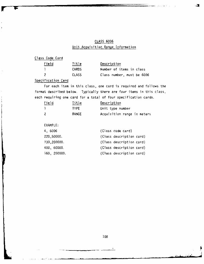
CLASS 6006
Unit Acquisition Range Information
Class Code Card
Field Title Description
I CARDS Number of items in class
2 CLASS Class number, must be 6006
Specification Card
For each item in this class, one card is required and follows the
format described below. Typically there are four items in this class,
each requiring one card for a total of four specification cards.
Field Title Description
1 TYPE Unit type number
2 RANGE Acquisition range in meters
EXAMPLE:
4, 6006 (Class code card)
220,50000. (Class description card)
130,200000. (Class description card)
400, 60000. (Class description card)
160, 200000. (Class description card)
108
..............................-

CLASS 6004
Payload Data Base
Class Code Card
Field Title Description
I CARDS Number of payload types in this class
2 CLASS Class number, must be 6004
Specification Cards
For each item in this class, two cards are required and follow the
format of cards A and B described below. There must be an A card for each
item and as many B cards as designated in field number 2 of card A.
Card A Format:
Field Title Description
1 ICLASS Payload type identification number
Must be 3 for air to ground
Must be 4 for air to air
2 INUM Number of items of this type to
follow
Card B Format:
Field Title Description
I INDEX Identification number, must be unique
identifier within this payload
type.
EXAMPLE:
2, 6004 (Class code card)
3, 3 (Card A)
I (Card B)
2 (Card B)
3 (Card B)
4, 1 (Card A)
I (Card B)
109 -_ _ "

CLASS 6003
Aircraft Data Base
Class Code Card
Field Title Description
1 CARDS Number of items in the class
2 CLASS Class number - must be 6003
Specification Cards
For each item in this class, two cards are required and follow the
format of cards A and B described below. There is one item in this class
for each aircraft type.
Card A Format:
Field Title Description
I TYPE Aircraft type number
401-419 BLUE interceptors
420-439 RED fighters440-459 RED fighter/bombers
460-479 RED bombers2 MAXSPEED Maximum speed in meters/seconds
3 CRUISESPEED Cruising speed in meters/seconds
4 MAXALTITUDE Maximum altitude in meters
5 MINALTITUDE Minimum altitude in meters
6 MAXCLIMBDIVE Maximum climb/dive rate in meters/
seconds
Card B Format:
Field Title Description
I FUELCONSUME Fuel consumption rate hex/second
2 ACQRANGE Acquisition range in meters
3 RADARCS Radar ARC
4 ATTACKRADIUS Attack radius in meters
5 MAXFUEL Maximum fuel load
EXAMPLE:
1, 6003 (Class Code Card)460, 420, 280., 15000., 100., 1500. (Card A)
1., 60000., 10., 800000., 200. (Card B)
110

CLASS 6005
Flight Prufiles
Class Code Card
Field Title Description
1 CARDS Number of items in class
2 CLASS Class number, must be 6005
Specificaton Cards
For each item in this class, one card is required and follows the
format described below. Typically there are four items in this class, each
requiring one card for a total of four specification cards.
Field Title Description
1 TYPE Profile identication number
2 ALTCREN Altitude of first leg in meters
3 ALTOTGT Altitude of second leg in meters
4 ALTOAB Altitude of third leg in meters
EXAMPLE:
2, 6005 (Class code card)
1, 10000., 10000., 10000. (Class description card)
5000., 500., 5000. (Class description card)
IIl

CLASS 6002
Flight Specifications
Class Code Card
Field Title Description
I CARDS Number of items in this class
2 CLASS Class number, must be 6002
Specification Cards
For each item in this class, two cards are required and follow the
format of cards A and B described below. There must be one A card for each
flight type and as many B cards as designated in Field number 9 of card A.
Card A Format:
Field Title Description
1 TYPE Flight specification number
2 IACTYPE Aircraft type number (400 series)
must match a number in class 6003,
card A, field I
3 MAXNOAC Maximum number of aircraft in flight
4 MINOAC Minimum number of aircraft in flight
5 MULTAC Multiples of aircraft required for
flight
6 PROFILE Profile identification number for
this flight. Must match an ID
number in field one of a class
6005 specification card.
7 SPFLTC Flight cruising speed in meters/seconds
8 DISTSEP Flight separation distance in meters
9 NOPAYS Number of payloads
Card B Format:
Field Title Description
I IPAYTYP Payload type identification number
(3 or 4)
2 MAXAMT Maximum number of loads of this payload
3 MINAMT Minimum number of loads of this payload
112

4 IPAYID Identification number of particular
payload within type. Must match a
number in field one of card 8,
class 6004.
EXAMPLE:
1, 6002 (Class Code Card)
7, 401, 4, 2, 2, 4, 350., 500., 3 (Card A)
4, 2, 2, 1 (Card 8)
4, 2, 2, 2 (Card B)
4, 4, 4, 3 (Card B)
113
'S -'',

CLASS 6001
Formation Specifications
Class Code Card
Field Title Description
1 CARDS Number of items in this class
2 CLASS Class number, must be 6001
Specification Cards
For each item in this class, at least two cards are required and
follow the format of cards A and B described below. There must be one card
A for each formation type and as many B cards as designated in field number
3 of card A.
Card A Format:
Field Title Description
I TYPE Formation type number
2 SPFORMC Formation cruise speed in mett;'-/
seconds
3 NOFLTS Number of flights in formation
Card B Format:
Field Title Description
1 IDFLITE Flight specification number must
match a number in class 6002,
card A, Field 1
EXAMPLE:
1, 6001 (Class Code Card)
4, 350., 3 (Card A)
7 (Card B)
5 (Card B)
2 (Card B)
114

CLASS 6007
Air Base Queue Specifications
Class Code Card
This class code is not implemented at this time, all values are MODEL
VALUES.
EXAMPLE:
1, 6007 (Class Code Card)
1, .005, 0., .2 (Class description card)
115

CLASS 6008
Initial Assignment of Aircraft to Air Bases
Class Code Card
Field Title Description
1 CARD Number of items in this class
2 CLASS Class number, must be 6008
Specification Cards
For each item in this class, two cards are required and follow the
format of cards A and B described below. There must be an A card for each
item and as many B cards as designated in field number 2 of card A.
Card A Format:
Field Title Description
1 IDAB Air Base number
2 NDACTYPES Number of aircraft types on air base
note: Limit of 1 for Blue air bases
(multiple air bases may be collocated)
Card B Format:
Field Title Description
1 ACTYPE Aircraft type number (400 series)
2 NUMACRFT Number of aircraft
3 FORMTYPE Formation type number
- required for blue air bases, and
must match class 6001, card A,
field 1.
- equals zero for red air bases
EXAMPLE:
2, 6008 (Class Code Card)
19, 2 (Card A)
460, 34, 0 (Card B)
440, 17, 0 (Card B)
15, 1 (Card A)
401, 11, 4 (Card B)
116
'A.
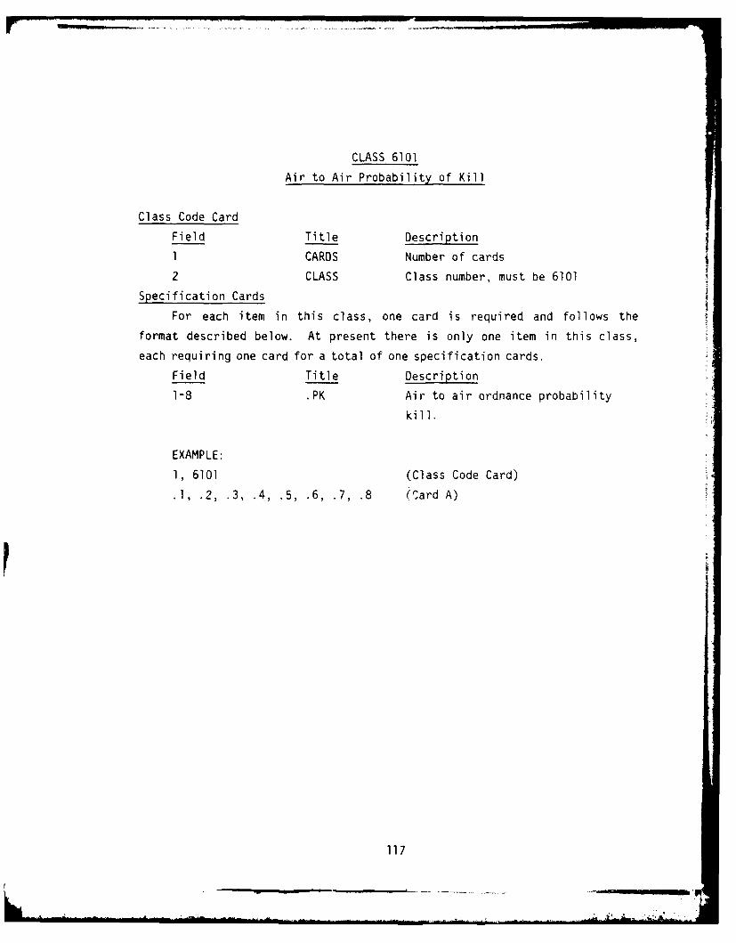
CLASS 6101
Air to Air Probability of Kill
Class Code Card
Field Title Description
1 CARDS Number of cards
2 CLASS Class number, must be 6101
Specification Cards
For each item in this class, one card is required and follows the
format described below. At present there is only one item in this class,
each requiring one card for a total of one specification cards.
Field Title Description
1-8 .PK Air to air ordnance probability
kill.
EXAMPLE:
1, 6101 (Class Code Card)
.1, .2, .3, .4, .5, .6, .7, .8 (Card A)
117

CLASS 6102
Air to Ground Probability of Kill
Class Code Card
Field Title Description
I CARDS Number of cards
2 CLASS Class number, must be 6102
Specitcation Cards
For each item in this class, one card is required and follows the
format described below. At present there are 26 items, and each card
naving 11 fields forms a 26 X 11 array.
Field Title Description
1-11 PK Probability of kill tables
EXAMPLE:
26, 6102 (Class Code Card)
0., 0., .2, .l, .9, .04, .02, .26, .31, .33, .4 (Class description card)
0., 0., 0., 0., .21, .33, .01, .12, .2, .35 (Class description card)
0., 0., 0., 0., .21, .33, .0l, .12, .2, .35
0., 0., 0., 0., 0., 0., 0., 0., 0., 0., 0., 0.
118

CLASS 6103
Surface-to-Air Probability of Kill
Class Code Card
Field Title Description
1 CARDS Must Equal 9
2 CLASS Class Number, must be 6103
Specification Cards
The equation to derive the probability of kill (PK) for surface to air
missiles (SAM) is: PK = A+B(R). The coeffeicients in the equation A and B
are used as inputs in the datfile. They are values that are derived from
the combination of 3 missile types and 3 ordinance types.
Field Title Description
I SAMPKA For a missile type and ordinance type
2 SAMPKB For the same missile type and ordinance
type
EXAMPLE:
9, 6103 (Class Code Card)
.447, -.OIE-5 A, B for Missile Type 1, Ordnance Type 1
.536, -4.0685E-6 A, B for Missile Type 2, Ordnance Type 1
.310, -1.6636E-6 A, B for Missile Type 3, Ordnance Type 1
.00, 0.0 A, B for Missile Type 1, Ordnance Type 2
.96, -1.004787E-6 A, B for Missile Type 2, Ordnance Type 2
.80, 0.0 A, B for Missile Type 3, Ordnance Type 2
.00,0.0 A, B for Missile Type 1, Ordnance Type 3
.00, 0.0 A, B for Missile Type 2, Ordnance Type 3
.90, 0.0 A, B for Missile Type 3, Ordnance Type 3
119

CLASS 6201
Air-to-Ground Probability of Death
Class Code Card
Field Title Description
I CARDS Number of cards
2 CLASS Class number, must be 6201
Specification Cards
For each item in this class, one card is required and follows the
format described below. At present a maximum of ten cards are allowed.
Field Title Description
1-8 PD Air to ground probability of death.
EXAMPLE:
10, 6201 (Class Code Card)
.68,0, 0., 0., .84, 1., 68, .68 (Class Description Card)
1., .68, 0., 0., 0., 0., .68, 0. (Class Description Card)
0., 0., .68, 0., .68, 0., 0., 1. (Class Description Card)
0., 0., 0., 0., 0., 0., 0., 0. (Class Description Card)
120
L •~

3. User Input Language File
The User Oriented Input Language File (UOIL) specifies the
scenario to be played. This specification consists of a list of commands
(stated in the user oriented input language described below) which indi-
cates the positions of various units, the command/control relationships of
the units and the structure of the Red Threat Plan. Allowable commands,
along with their proper syntax, are listed below. Each sentence is com-
posed of two types of words: constants and variables. Some constants and
variables have optional plurals and abbreviations that are shown below.
The variable options are listed below each sentence by words in all capital
letters. For a complete example of an input language file see the test
case in Chapter V of this manual.
. NUMBER UNITTYPE commands NUMBER UNITTYPE.
Where NUMBER = An integer NUMBER
Where UNITTYPE = HAWKBTRY
HERCBTRY
PATBTRY
HAWKBOC
HERCBOC
PATBOC
CRC
AIRBASE
TAB
AWACS
LANCE
HJ
BRIDGE
DEPOS
PERSHING
POL
SASP
121
... ... - ---- -- -- _-.- --- -- _--- - - It

ASP
RESERVES
TRAINS
C LVBTRY
VIIIBTRY
CORPBTRY
COR PC P
oIVCP
SOC
ATA F
Optional Plurals: HAWKBTRY =HAWKBTRYS
HERCBTRY = HERCBTRYS
AIRBASE =AIRBASES
SASP = SASPS
ASP = ASPS
RESERVE = RESERVES
TRAIN = TRAINS
CLVBTRY =CLVBTRYS
VIIIBTRY =VIIIBTRYS
CORPCP =CORPUPS
DIVCP = IVCPS
Optional Abbreviations: CRC =CRP
CRC = GP
CRC = GRDUP
CRC = MCC
AIRBASE =AB
commands cmds
commands c
122

Example:
99 ATAF commands 1 CRC.
1 CRC cmds 4 HAWKBOC.
3 HAWKBOC cmds 28 HAWKBTRY.
Hex NUMBER has altitude NUMBER LUNIT.
Where NUMBER An integer NUMBER
Where LUNIT = FEET
METERS
Optional Abbreviations: altitude = alt
feet = ft
meters = m
Example:
Hex 7752352 has altitude 300 feet.
Hex 7753413 has alt 400 m.
* Buffer zone width is NUMBER km.
Where NUMBER = An integer NUMBER
Example:
Buffer zone width is 40 km.
* Random seed is NUMBER.
Where NUMBER = An integer NUMBER
123
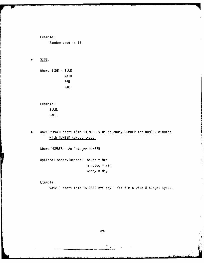
Example:
Random seed is 16.
0 SIDE.
Where SIDE = BLUE
NATO
RED
PACT
Example:
BLUE.
PACT.
0 Wave NUMBER start time is NUMBER hours onday NUMBER for NUMBER minutes
with NUMBER target types.
Where NUMBER = An integer NUMBER
Optional Abbreviations: hours = hrs
minutes = min
onday = day
Example:
Wave 1 start time is 0630 hrs day 1 for 5 min with 5 target types.
124
.: i . .. '

Target type unittype NUMBER formation NUMBER NUMBER km range limits.
Where UNIT TYPE = HAWKBTRY
HERCBTRY
PATBTRY
HAWKBOC
HERCBOC
PATBOC
CRC
AIRBASE
TAB
AWACS
LANCE
HJ
BRIDGE
DEPOS
PERSHING
POL
SASP
ASP
RESERVES
TRAINS
CLVBTRY
VIIBTRY
CORPBTRY
CORPCP
DIVCP
SOC
ATAF
Where NUMBER = An integer NUMBER
Optional Plurals: HAWKBTRY = HAWKBTRYS
HERCBTRY = HERCBTRYS
125
-. "'.

AIRBASE = AIRBASES
SASP = SASPS
ASP = ASPS
RESERVE = RESERVES
TRAIN = TRAINS
CLVBTRY = CLVBTRYS
VIIIBTRY = VIIIBTRYS
CORPCP CORPCPS
DIVCP = DIVCPS
formation = formations
Optional Abbreviations: CRC = CRP
CRC = GP
CRC = GRDUP
CRC = MCC
AIRBASE = AB
Example:
Target type HAWKBTRYS, 1 formation 90, 0 km range limits.
Target type PERSHING, 1 formation 200, 50 km range limits.
Target NUMBER1 unittype is at NUMBER2 latitude NUMBER2
longitude.
Where NUMBERI = An interger target ID number
Where NUMBER2 = A real decimal degree
Where UNITTYPE = HAWKBTRY
HERCBTRY
PATBTRY
HAWKBOC
HERCBOC
PATBOC
126

CRCAIRBASE
TAB
A WAGCS
LANCE
HJ
BRIDGE
D EP0 S
PERSHINGP0 L
SAS P
ASP
RESERVES
TRAINS
C LVBTRY
VIIIBTRY
CORPBTRY
CO RPC P
DIVCP
SOCATAF
Optional Plurals: HAWKBTRY = HAWKBTRYS
HERCBTRY = HERCBTRYS
AIRBASE =AIRBASES
SASP =SASPS
ASP =ASPS
RESERVE = RESERVES
TRAIN = TRAINS
CLVBTRY =CLVBTRY
VIIIBTRY =VIIIBTRYS
CORPCP = CORPCPS
127

DIVCP = DIVCPS
latitude = latitudes
longitude = longitudes
Optional Abbreviations: CRC = CRP
CRC = GP
CRC = GROUP
CRC = MCC
AIRBASE = AB
latitude = lat
longitude = long
Example:
Target, 23 SASP is at 50.0 lat, 8.4 long.
Target, 27 TRAIN is at 48.9 lat, 10.8 long.
* Target NUMBER UNITTYPE is at hex NUMBER.
Where NUMBER = An integer NUMBER
Where UNITTYPE HAWKBTRY
HERCBTRY
PATBTRY
HAWKBOC
HERCBOC
PATBOC
CRC
AIRBASE
TAB
AWACS
LANCE
HJ
128

BRIDGEOEPOS
PERSHING
POL
SASP
ASP
RESERVES
TRAINS
CLVBTRY
VIIIBTRY
CORPBTRY
CORPCP
DIVCP
SOC
ATAF
Optional Plurals: HAWKBTRY = HAWKBTRYS
HERCBTRY = HERCBTRYS
AIRBASE = AIRBASES
SASP = SASPS
ASP ASPS
RESERVE = RESERVES
TRAIN = TRAINS
CLVBTRY = CLVBTRYS
VIIISTRY = VIIIBTRYS
CORPCP = CORPCPS
Optional Abbreviations: CRC CRP
CRC GP
CRC GROUP
CRC = MCC
AIRBASE = AB
129
-- ~ ~ - I ~L. A -

Example:
Target 13 ATAF is at HEX 7752352.
* Raid NUMBER has NUMBER wave thru NUMBER corridor.
Where NUMBER = A real NUMBER
Optional Plurals: raid = raids
wave = waves
corridor = corridors
Example:
Raid 23 has 3 wave thru 2 corridor.
* Raid NUMBER.
Where NUMBER = An integer NUMBER
Optional Plurals: raid = raids
Example:
Raid 4.
o Red theater operations.
Optional Plurals: theater - theaters
Example:
Red theater operations.
130
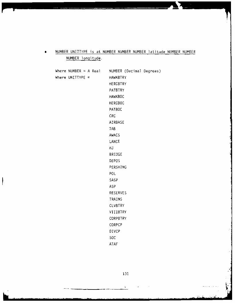
NUMBER UNITTYPE is at NUMBER NUMBER NUMBER latitude NUMBER NUMBER
NUMBER longitude.
Where NUMBER = A Real NUMBER (Decimal Degrees)
Where UNITTYPE = HAWKBTRY
HERCBTRY
PATBTRY
HAWKBOC
HERCBOC
PATBOC
CRC
AIRBASE
TAB
AWACS
LANCE
HJ
BRIDGE
DEPOS
PERSHING
POL
SASP
ASP
RESERVES
TRAINS
CLVBTRY
VIIIBTRY
CORPBTRY
CORPCP
DIVCP
SOC
ATAF
131

Optional Plurals: HAWKBTRY = HAWKBTRYS
HERCBTRY = HERCBTRYS
AIRBASE = AIRBASES
SASP - SASPS
ASP = ASPS
RESERVE = RESERVES
TRAIN = TRAINS
CLVBTRY = CLVBTRYS
VIIIBTRY = VIIIBTRYS
CORPCP = CORPCPS
DIVCP = DIVCPS
latitude = latitudes
longitudes = longitudes
Optional Abbreviations: CRC = CRP
CRC = GP
CRC = GRDUP
CRC = MCC
AIRBASE = AB
latitude = lat
longitude = long
Example:
4 HAWKBOC is at 49.0 lat 11.9 long.
15 AIRBASE is at 50.2 lat 8.0 long.
14 HERCBTRY is at 48.3 lat 11.4 long.
Label.
Example:
Label.
MADEM TEST RUN
Label.
FINAL TEST RUN
132

* Game starts at NUMBER hours on day NUMBER.
Where NUMBER = An integer NUMBER
Optional Abbreviations: HOURS = HRS
Example:
Game starts at 1100 hours on day 1.
Corridor NUMBER limits are NUMBER latitude NUMBER longitude
NUMBER latitude NUMBER longitude.
Where NUMBER = A real NUMBER (Decimal Degress)
Optional Plurals: latitude = latitudes
longitude = longitudes
Optional Abbreviations: latitude = lat
longitude = long
Example:
Corridor 1 limits are 50.25 lat, 12.0 long, 50.33 lat, 11.64 long.
Corridor NUMBER limits are NUMBER NUMBER NUMBER latitude NUMBER NUMBER
NUMBER longitude.
Where NUMBER = An integer NUMBER
Optional Plurals: latitude = latitudes
longitude = longitudes
Optional Abbreviations: latitude = lat
longitude = long
133

Example:
Corridor 4 limits are 48.6 latitude 10.3 longitude.
Corridor NUMBER depth is NUMBER km heading NUMBER degree spread angle
NUMBER degree.
Where NUMBER = An integer NUMBER
Optional Plurals: degree = degrees
Optional Abbreviations: degree = deg
Example:
Corridor 1 depth is 70 km. heading 245 deg. spread angle 60 deg.
NUMBER type NUMBER formation.
Where NUMBER = An integer NUMBER
Optional Plurals: formation formations
Example:
6 type 3 formations.
* NUMBER UNITTYPE is at hex NUMBER.
Where NUMBER = An integer NUMBER
Where UNITTYPE HAWKBTRY
HERCBTRY
PATBTRY
HAWKBOC
134
... ....

HERCBOC
PATBOC
CRC
AIRBASE
TAB
A WAC S
LANCE
HJ
BRIDGE
DEPOS
PERSHING
P0 L
SAS P
ASP
RESERVES
TRAINS
CLVBTRY
VIIIBTRY
CORPBTRY
CO RPC P
DIVCP
SOC
ATA F
Optional Plurals: HAWKBTRY = HAWKBTRYS
HERCBTRY =HERCBTRYS
AIRBASE =AIRBASES
SASP =SASPS
ASP =ASPS
RESERVE = RESERVES
TRAIN = TRAINS
CLVBTRY = CLVBTYS
135

VIIIBTRY = VIIIBTRYS
CORPCP = CORPCPS
DIVCP = DIVCPS
Optional Abbreviations: CRC = CRP
CRC = GP
CRC = GRDUP
CRC = MCC
AIRBASE = AB
Example:
10 HAWKBTRY is at HEX 774225.
12 PATBTRY is at HEX 7777526.
D. MAIN PROCESSOR (RUNBIN)
MADEM's main processor (RUNBIN) requires two primary inputs: a set of
Run Parameter Cards and a set of two Hold Files. Each of these required
inputs is described below.
1. Run Parameter Cards
The Run Parameter Cards control the main processor run. There
are two card types. The first is mandatory. The second is optional. The
formats of these cards are listed below:
CARD 1:
PARM 1 - Must be integer '2' for RUNBIN
PARM 2 - Integer, max size of ISPACE. (100000)
PARM 3 - Integer, max number of payers on either side.
PARM 4 - Real, max CPU time of volume (in seconds)
PARM 5 - Real, max game time of this volume.
PARM 6 - Integer, max number of events for this volume.
136

CARD 2 TO THE LAST CARD:
The second set of options are all optional. Each of these
PARMS must begin in column 11. There may be only I Parm
Per card, with as many cards as are necessary. It is
recommended that these options be used only when debugging
PARMS:
'DEBUG=ON' - Turns on full debug mode
'DUMP=ON' - Will dump ISPACE at end of volume.
'RECOR=OFF' - Turn off system recovery routine
EXAMPLE:
2,100000,600,250,999999,20000
DEBUG=ON
DUMP=ON
2. Hold Files
The two Hold Files that are used as input to the MADEM main
processor are created by the preprocessor. These files need not concern
the user because they are automatically saved and accessed by the current
Job Control Language (JCL). This will allow the entire data base to be
saved for restarts of the main processor.
E. POSTPROCESSOR (HISTBIN)
MADEM's postprocessor (HISTBIN) provides printed summaries of a
variety of MADEM events. It requires two inputs: a set of Run Parameter
Cards and History Files. Each of these required inputs is described below.
1. Run Parameter Cards
The Run Parameter Cards control the main processor run. There
are two card types. The formats of these cards are listed below:
CARD 1:
Up to 70 character description of the scenario.
137
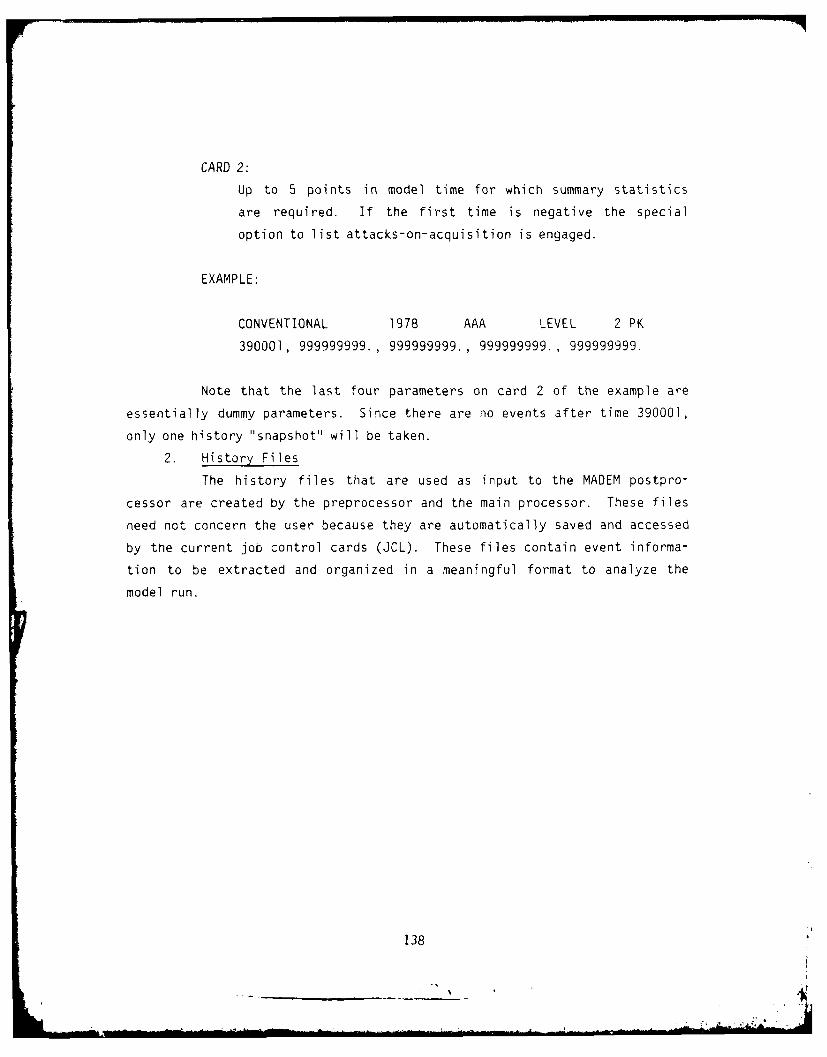
CARD 2:
Up to 5 points in model time for which summary statistics
are required. If the first time is negative the special
option to list attacks-on-acquisition is engaged.
EXAMPLE:
CONVENTIONAL 1978 AAA LEVEL 2 PK
390001, 999999999., 999999999., 999999999., 999999999.
Note that the last four parameters on card 2 of the example are
essentially dummy parameters. Since there are no events after time 390001,
only one history "snapshot" will be taken.
2. History Files
The history files that are used as input to the MADEM postpro-
cessor are created by the preprocessor and the main processor. These files
need not concern the user because they are automatically saved and accessed
by the current job control cards (JCL). These files contain event informa-
tion to be extracted and organized in a meaningful format to analyze the
model run.
138

SECTION VI
EXAMPLE CASE
A. INTRODUCTION
The purpose of this chapter is to describe all of the required inputs
and resulting outputs Fssociated with a simple MADEM scenario. The
scenario used in this example case is a variant of the basic test data set
which was used to develop and debug the current version of MADEM. Section
B describes the basic elements of the scenario while sections C and D
describe the required inputs and resulting outputs.
B. SCFNARIO SPECIFICATION
1. General Description
The scenario used in this example represents a considerable
simplification of typical MADEM analysis run. While the overall configura-
tion of units is realistic, the total unit density in the simulated battle
area is much lower than the actual unit density in the 2 ard 4 ATAF area
represented in the scenario. This lower unit density was used to simplify
the scenario for explanatory purposes and to reduce the run time and
storage requirements for testing.
2. Unit Locations and C2 Relationshios
Figure VI-I shows the locations of all units in the scenario and
their command/control relationships. Figure Vi-2 shows the LAT/LONG over-
lay used to input unit locations in the user input language file. The Red
theater commander, located to the right of the border line, commands four
Red airbases. Each of the two combat reporting centers on the blue side
commands two airbases, and two battalion operations centers. Each HAWK BOC
in turn commands three HAWK batteries, while each Nike-Hercules BOC com-
mands two Nike-Hercules batteries. In addition, a number of passive tar-
gets have been included on the Blue side to draw additional red attacks.
It should be noted that these passive targets are not connected to the C2
tree and do not play an active role in the battle.
139

o
0
4368179W
Figure 111-1. Locations andC 2 Relationships
140

o
60 7 80 9 0 00 0 10 10 14 150 16 17
53
I ~I~52o
51
4368179W
Figure VI-2. Latitude and Longitude Overlay
141

3. Blue Air Defense Specification
The Blue side's defensive assets include the aircraft on the four
blue airbases and the ten SAM batteries. Each of the Blue airbases has
been assigned 12 interceptor aircraft. rhese interceptors must fly in
flights of 2 to 4 aircraft. Each HAWK battery has been supplied with 18
conventional missiles. Nike-Hercules batteries have been supplied with 14
conventional missiles each. All blue SAM batteries will be resuppiied with
2 missiles every 6 hours. Missile fire ranges for all batteries are
indicated in Figure VI-3. Further details of the Blue defenses can be
found in the sample data base file in figure VI-6 in section C.1 of this
chapter.
4. Red Attack Specification
The aircraft on the red airbases constitute the Red side's pri-
mary offensive assets. Assignments of aircraft to the four red airbases
are as follows:
AIRBASE BOMBERS FIGHTER/BOMBERS FIGHTERS
19 34 15 11
20 32 24 9
21 32 23 17
22 36 24 16
In contrast to the simple flight assignment used on the Blue side, a more
complex assignment of aircraft to flight and formation types has been used
on the Red side. Specified flight assignments for the Red side include the
following:
FLIGHT TYPE NUMBER OP AIRCRAFT
6 2 - 4 FIGHTERS
5 2 - 6 FIGHTERS
4 2 - 4 FIGHTER/BOMBERS
3 3 - 6 FIGHTER/BOMBERS
2 8 - 72 BOMBERS
1 4 - 16 BOMBERS
142

r38nV
~~143

It should be noted that each of the above flight types carries a different
user defined weapons package.
These Red flights must be further grouped into formation types
for assignment to Blue targets. Specified formation types are as follows:
FORMATION TYPE FLIGHT TYPES IN THE FORMATION
3 2 - 4 FIGHTER/BOMBERS - Type 4
2 3 - 6 FIGHTER/BOMBERS - Type 3
2 - 6 FIGHTERS - Type 5
8 - 12 BOMBERS - Type 2
4 - 16 BOMBERS - Type 1
2 - 4 FIGHTERS - Type 6
In this scenario these formation types have been used to specify a two wave
raid on the Blue side. The specification parameters for each wave in the
raid are discussed below. The Red attack plans, which the model generates
from these specifications, are discussed in section 0.1 of this chapter.
a. First Wave - Corridor Clearing
The first wave attack specifications for this scenario are
illustrated in Figure VI-4. The purpose of this wave is to clear the
attack corridors of SAM batteries. The specifications for this wave are
input in the user input language file listed in section C.l of this
chapter. They specify two attack corridors with 40 km buffer zones. Up to
6 type 3 formations may be assigned by the red theater planner to attack
HAWK batteries within 90 km of the corridor exits. Up to 2 type 1 forma-
tions may be assigned by the red theater planner to attack Nike-Hercules
batteries within 190 km of the corridor exits. It should be noted that
these are the maximum allocations input by the user. They act as con-
straints upon the actions of the model which may assign fewer formations
than specified due to lack of aircraft.
b. Second Wave - Deep Penetration
Figure VI-5 illustrates the second wave attack specifica-
tions for this scenario. The same two corridors have been specified for
144

0
114

4368(79W
Figure VI-5. Second W~ave Attack Specifications
146

use in this wave as in the first wave. Corridors should have been cleared
of SAM batteries in the first wave. The primary purpose of this wave is to
penetrate deep into Blue air-space to attack airbases and passive targets.
If further corridor clearing is required up to 4 type 3 formations may be
assigned to attack HAWK batteries within 150 km of the corridor exit.
Airbases may be attacked with up to 4 type 2 formations. The two types of
passive targets (SASPS and HJ's) may be attacked with up to 2 type 1 plus 2
type 2 and 2 type 1 formations respectively.
C. REQUIRED INPUTS
A MADEM simulation is run in three stages: the preprocessor, the main
processor, and the post processor. The main processor can run in several
volumes, generally between six and twelve volumes. MADEM runs at the AFWL
computer center on either of the two CDC Cyber 176 computers (MFY or MFX).
MADEM cannot run the Cyber 166, referred to as MF 'B.
This section includes all the required inputs to run an example MADEM
simulation, including Job Control Language (JCL) to run all three stages of
MADEM as well as the Data Base File and User Oriented Input Language File
(UOIL) necessary to run the preprocessor. In the sample JCL streams, the
second card, the account card, will have to be altered to provide a valid
account number and password. See Appendix D for explanations of the first
two JCL cards and the end-of-record and end-of-information cards.
1. Preprocessor Input
To run the preprocessor for our example case the following perm-
anent files must reside on the AFWL system:
MADEMINITBIN - Executable preprocessor program
DATFILEEXAMPLE - Example data base.
UOILEXAMPLE - Example User Input Language File.
See figures VI-6 and VI-7 respectively, for the sample Data Base File and
the sample User Oriented Input Language File.
147

DATFILE TEST CASE I -- CONVENTIONAL 4 DEC 19796026180,1,3,30,15,75.,0.,10.,0.,0.1,1 ,2,5,3,1000000,90.,150000.,9,11,0.,180000.,15.0.,0.,14,0,0,21600,2,O,0,0,0175,1,12,30,15,75.,0.,10.,0.,0.1,1,2,5,3,1000000,60.,90000.,0,11,0.,100000.,15.0 ,0.,20,0,0,21600,2,0,0,0,07!,1,3,30,15,75. ,0. ,10. ,0. ,0.' .2, 5,3,1000000,45.,50000.,0,11,0.,100000.,15.
0.,0.,18,0,0,21600,2,0,0,0,0160,1,3,30,15,75. ,37. ,10. ,0. ,0.1,1,2,5,3,100000,90.,150000.,1,8,5.,5.,5.0.,0.,0,0,0,0,0,0,0,0,0155,1,15,30,15,75.,37.,30.,0.,0.1,1,2,5,3,1000000,60.,90000.,1,8,5.,5.,5.0.,0.,0,0,0,0,0,0,0,0,0150,1,3,30,15,75.,37.,10.,0.,0.1,1,2,5,3,1000000,45.,50000.,1,8,5.,5.,5.0.,0. .,0 0,0,0 ,0,0,0 , 0,7,6006220,50000.130,200000.400,60000.160,200000.150,200000.130,300000.170,100000.2,60043,61234564,31234,6003460,420,280.,15000.,10,j.,1500.1.,60000.,10.,800000.,200.440,435.,290.,17000.,50.,1500.1.,60000.,4.,800000.,200.420,480.,320.,20000.,50.,1500.1.,60000.,2.,800000.,200.
Figure VI-6. Sample Data Base File
148

401 ,525. ,350. ,20000.,150. ,1500.1. ,60000. ,3. ,800000. ,200.4,60054,10000. ,10000. ,10000.8,5000. ,5000. ,5000.2,500. ,500. ,5000.1,5000. ,500. ,5000.7,60027,401 ,4,2,2,4,350,500. ,3
2,2,14,2,2,24,4,4,36,420,4,2,1 ,3,320. ,500. ,24,3,3,14)4,4,25,420,6,2,1,2,320. ,500. ,24,4,4,14,2,2,24 ,440,4,2,1,1 ,290. ,500. ,34 ,2,2,23,4,4,43,4,4,63,440,6,3,1,2,290. ,500. ,34,3,3,13,8,8,43,2,2,62,460,12,8,2,3,280. ,500. ,l3,6,6,51,460,16,4,2,3,280. ,500. ,23,4,4,53,2,2,64,600 14,350. ,l7
290. ,l42,280. ,33521,280. ,2
61 ,60071 ,.005,0. ,.28,600819,3460,34,0440,15,0
Figure VI-6. Sample Data Base rile (Continued)
149

420,11,020,3460,32,0440,24,0420,9,021,3460,32,0440,23,0420,17,022,360,36,0
440,24,0420,16,015,1401 ,12,416,1401,12,4
7,1401,12,418,1401,12,41,6101.25,.24,.26,.25,.02,.26,.25,.02,.0,.026,6102.0 .0 ,.0 ,.0 ,.0013: .0 ,.0403,. 1624,.0 .0 ,.0
.0 .0 ,.0 ,.0 ,.0013,.0 ,.0403,.0 ,.0 ,.0 ,.0
.0 0 ,. 3687,.9567,.0 .0988,.0 .0 ,.0 ,.0 ,.0
.0 0 ,.3014,.0 .0 .0 ,.0 .0 ,.0 ,.0 ,.0
.0 .0 ,.3014,.0 .0 .0 ,.0 .0 ,.0 .0 ,.0
.0 ,.0287,.0316,.0 .0322,.0 ,.0 .0 ,.0 ,.0 ,.0
.0 .0305,.0 ,.0 .0 .0 ,.0 .0 ,.0 .0 ,.0
.0 .0646,.0 ,.0 .0 .0 ,.0 .0 ,.0 ,.0 , 00 1456,.0 ,.0 .0 0 ,.0 .0 ,.0 ,.0 ,.0
.0 .5236,.0 .3638,.0 0 ,.0 .0 .0 ,.0 ,.0
.0 ,.0 ,.0 .0 .0626,.0 ,.0 .0 .0 ,.0 ,.0
.2435,,0800,.0 ,.0 .0 .1663,.2493,.0 .0 ,.0 ,.0
.4986,.0 ,.0 .0 .0 .0 ,.2500,.0 .0 ,.0 ,.0
.4950,.2240,.0 .0 .0 ,0 ,.2430, .0 .0 .0 ,.0
.0 .0020,.0 .0044,.0 .0 .O .0 .0 ,0 ,.0
.0 .0 .1840,.0 ,0 .0 ,.0 .0 .0 .0 .0
.0 .0 .1840,.0 .0 .0 ,,0 .0 .0 .0 ,.0
.0 .0 .1840,.0 .0 .0 ,.0 ,0 .0 ,.0 ,.0
.0 .0 .0 .0 .7664,.0 ,.0 .0 .0 .0 ,.0
.0 .0 .1840,.0 .0 ,.0 .0 .0 .0 .0 ,.0
.0 .0 .0 .0 2250,-0 .5030, .0 .0 .0 ''0
.0 ,0 .0700,.0 .0 , 0 .0 .0 ,0 .0 ,.0
.0 -0158-0 .0593,.0 ,.0 .0 .0 .0 ,.0 .0
.0 -0306-0 .0 .0 ,.0 ,0 0 .0 ,.0 .0
.0 .0 .0 .0 .0 ,.0 .u ,.0 .0 .0 ,.0
.0 ,.0 .0 ,.0 .0 ,.0 ,.0 .0 _0 ,.0 ,.0Figure VI-6. Sample Data Base File (Continued)
150

9,6103.447, -1.01E-5.536, -4.0685E-6.310, -1.6636E-6
.00, 0.0
.96, -1.004787E-6
.80, 0.0
.00, 0.0
.00, 0.0
.90, 0.010,6201.68,0. ,0. ,0.1,.84,1. ,. 68, .681. ,.68,0. ,0. ,0. ,0. ,.67,0.0. ,0. ,.68,0. ,.68,0. ,0. ,1..68,0.,0.,1.,0.,0.,.68,0.0. ,0. ,0. ,0. ,0. ,0. ,.84,0.
0. ,.67,0. ,0. ,0. ,0. ,.68,0.0. ,0. ,0. ,.84,1. ,0. ,.68,0.0. ,0.,0. ,0.,0. ,0.,0. ,0.0.,0. ,0.,0. ,0. ,0. ,0,0o.
Figure VI-6. Sample Data Base File (Continued)
151

LABEL.MADEM TEST RUN b MAY 1977LABEL.FINAL TEST RUN WITH INPUT AND PLANBLUE.99 ATAF COMMANDS 1 CRC.1 CRC IS AT 49.7 LAT 10.0 LONG.99 ATAF COMMANDS 2 CRC.2 CRC IS AT 49.2 LAT 9.7 LONG.1 CRC COMMANDS 3 HAWKBOC.3 HAWKBOC IS AT 49.5 LAT 11.1 LONG.1 CRC COMMANDS 4 HAWKBOC.4 HAWKBOC IS AT 49.0 LAT 11.9 LONG.2 CRC COMMANDS 5 HERCBOC.5 HERCBOC IS AT 49.8 LAT 9.1 LONG.2 CRC COMMANDS 6 HERCBOC.6 HERCBOC IS AT 48.6 LAT 10.3 LONG.3 HAWKBOC COMMANDS 7 HAWKBTRY.7 HAWKBTRY IS AT 50.1 LAT 10.8 LONG.3 HAWKBOC COMMANDS 8 HAWKBTRY.8 HAWKBTRY IS AT 49.9 LAT 11.5 LONG.3 HAWKBOC COMMANDS 28 HAWKBTRY.28 HAWKBTRY IS AT 49.58 LAT 12.02 LONG.4 HAWKBOC COMMANDS 9 HAWKBTRY.9 HAWKBTRY IS AT 49.3 LAT 12.3 LONG.
HAWKBOC COMMANDS 10 HAWKBTRY.10 HAWKBTRY IS AT 49.0 LAT 12.1 LONG.4 HAWKBOC COMMANDS 29 HAWKBTRY.29 HAWKBTRY IS AT 49.1 LAT 12.7 LONG.5 HERCBOC COMMANDS 11 HERCBTRY.11 HERCBTRY IS AT 50.1 LAT 9.7 LONG.5 HERCBOC COMM1ANDS 12 HERCBTRY.12 HERCBTRY IS AT 49.4 LAT 11.2 LONG.6 HERCBOC COMMANDS 13 HERCBTRY.13 HERCBTRY IS AT 49.1 LAT 10.8 LONG.6 HERCBOC COMV'A:DS 14 HERCBTRY.14 HERCBTRY IS AT 48.3 LAT 11.4 LONG.1 CRC COMMANDS 15 AIRBASE.15 AIRBASE IS AT 50.2 LAT 8.0 LONG.1 CRC COMMANDS 16 AIRBASE.16 AIRBASE IS AT 49.4 LAT 8.4 LONG.2 CRC COMMANDS 17 AIRBASE.17 AIRBASE IS AT 48.8 LAT 8.2 LONG.2 CRC COMMANDS 18 AIRBASE.18 AIRBASE IS AT 48.2 LAT 8.8 LONG.TARGET, 23 SASP IS AT 50.0 LAT, 8.4 LONG.TARGET, 24 SASP IS AT 49.2 LAT, 7.8 LONG.TARGET, 25 SASP IS AT 49.1 LAT, 10.2 LONG.
Figure VI-7. User Oriented Input Language File
152

TARGET, 26 SASP IS AT 48.0 LAT, 8.6 LONG.TARGET, 27 HJ IS AT 48.9 LAT, 10.8 LONG.RED.30 WP COMMANDS 19 AIRBASE.30 WP IS AT 51.5 LAT, 13.8 LONG.19 AIRBASE IS AT 51.4 LAT, 11.4 LONG.30 WP COMMANDS 20 AIRBASE.20 AIRBASE IS AT 51.1 LAT, 12.4 LONG.30 WP COMMANDS 21 AIRBASE.21 AIRBASE IS AT 50.35 LAT 14.08 LONG.30 WP COMMANDS 22 AIRBASE.22 AIRBASE IS AT 50.1 LAT, 14.2 LONG.RED THEATER OPERATIONS.RAID ICORRIDOR I LIMITS ARE 50.25 LAT, 12.0 LONG, 50.33 LAT, 11.64 LONG.CORRIDOR 1 DEPTH IS 70 KM, HEADING 245 DEG, SPREAD ANGLE 60 DEG.BUFFER ZONE WIDTH IS 40 KM.CORRIDOR 2 LIMITS ARE 49.5 LAT, 12.9 LONG, 49.63 LAT, 12.72 LONG.CORRIDOR 2 DEPTH IS 60 KM, HEADING 230 DEG, SPREAD ANGLE 60 DEG.BUFFER ZONE WIDTH IS 40 KM.WAVE I START TIME IS 0630 HRS DAY 1 FOR 5 MIN.TARGET TYPE HAWKBTRYS, 1 FORMATION 90,0 KM RANGE LIMITS.6 TYPE 3 FORMATIONS.TARGET TYPE HERCBTRYS, I FORMATION, 190,20 KM RANGE LIMITS.2 TYPE 1 FORMATIONS.WAVE 2 START TIME 15 0645 HRS DAY 1 FOR 10 MIN.TARGET TYPE HAWKBTRYS, 1 FORMATION, 150,0 KM RANGE LIMITS.
TYPE 3 FORMATIONS.TARGET TYPE AIRBASES, I FORMATION,400,150 KM RANGE LIMITS.4 TYPE 2 FORMATIONS.TARGET TYPE SASPS, 2 FORMATIONS, 440, 60 KM RANGE LIMITS.2 TYPE I FORMATIONS.2 TYPE 2 FORMATIONS.TARGET TYPE HJ, I FORMATION, 200,50 KM RANGE LIMITS.2 TYPE 1 FORMATIONS.
Figure VI-7. User Oriented Input Language File (Continued)
153

a. Preprocessor Job Control Language
The preprocessor job control stream in figure VI-8 will
execute the MADEM example preprocessor. The COMMENT cards are for your
information only, and may be omitted. The three REQUEST cards allocate
permanent file space for the History File (TAPE4) and the two Hold Files.
The ATTACH cards access the necessary permanent files listed above. After
executing INITBIN, the History File and the two Hold Files are saved as
permanent files, and the planner output in TAPE14 is sent to the printer.
Everything after the EXIT card is only executed if the system abnormally
aborts the job stream. In this case debug information will be sent to theprinter.
b. Preprocessor Run Parameters
The next to last card in the job stream is the Run Para-
meters card. In includes six parameters:
(1) a one for INITBIN.
(2) size of ispace (50,000)
(3) maximum number of players on either side (600)
(4) dummy value (25)
(5) dummy value (999999)
(6) dummy value (I)
2. Main Processor Inputs
A full production run is generally run in volumes, but may be
accomplished in one run. If it is run in volumes, the simulation's memory,
contained in an array called ISPACE, is saved on Hold Files to be used in
starting the next volumes. The length of a volume is controlled by the
fourth, fifth, and sixth run parameters (see Section (b) below). A large
production run will use about 2,000 (3,720 octal) CP seconds and about 120
(170 octal) I/0 seconds, thus running at prinrity P10. Volumes of about
30,000 events each will use about 200 (310 octal) CP seconds and 10 I'C
seconds, thus running at priority P60. A large run could take between
eight and twelve of these volumes. For an explanation of these job card
parimeters, 3ee Appendix 0 or an AFWL SYSBULL.
154
r'

MADEM,ST176,T30,IO50,P66,EC150. MADEM PREPROCESSOR (EXAMPLE)ACCOUNT MADEM,**A****-ZZZ,BDM,703-821-4223. B MACALEERCOMMENT.**A***A**A****A**COMMENT. *COMMENT. * MADEM PREPROCESSOR (EXAMPLE):COMMENT. PLANS RED RAID *
COMMENT. * READS DATFILE, UOIL INPUTCOMMENT. * GENERATES ISPACECOMMENT. * SAVES ISPACE ON HOLD FILESCOMMENT.COMMENT. FILES:COMMENT. TAPE4 - HISTORY FILE A
ZOMMENT. TAPE7 - UOIL INPUTCOMMENT. TAPE8 - DATFILE INPUTCOMMENT. TAPE1O - FIRST HOLD FILECOMMENT. TAPEll - SECOND HOLD FILE *
COMMENT. TAPE14 - PRINTED PLANNER OUTPUT *COMMENT. A
COMMENT. AAAAA*A*AAA***A**A*
REQUEST,TAPE4,*PF.REQUEST,TAPEIO,APF.REQUEST,TAPEII,*PF.ATTACH,TAPE7,UOILEXAMPLE,ID=WDNA14V6.ATTACH,TAPE8,DATFILEEXAMPLE,ID=WDNA14V6.ATTACH,INITBIN,MADEMINITBIN,ID=WDNA14V6.LDSET.PRESET=ZERO.LOAD,INITBIN.EXECUTE.REWIND,TAPE4,TAPE1O,TAPEII,TAPE]4.COMMENT. *A*** ** AAAAA******AAACOMMENT. * SAVE HISTORY FILE AND HOLD FILESCOMMENT. A*AAAAA*AAAAAAAAAA*AA*AA*AAAA*ACATALOG,TAPE4,EXAMPLEHISTPLAN,ID=WDNAI4V6,RP=999.CATALOG,TAPE1O,EXAMPLEPLAN1,ID=WDNA14V6,RP=999.CATALOG,TAPE11,EXAMPLEPLAN2,ID=WDNA14V6,RP=999.COMMENT. ****A ******A*A***AAAAA** A*ACOMMENT. A GET PRINTED OUTPUT A
COMMENT. ****A *A ** **AA**AAAACOPYBF,TAPE14,OUTPUT.COMMENT. ****A******AA***** A***A*AAAACOMMENT. FIRST INPUT CARD IS MANDATORY AND *COMMENT. * HOLDS 6 PARAMETERS: A
COMMENT. * 2. MUST BE 1 FOR PREPROCESSORCOMMENT. 2. SIZE OF ISPACE (50000) *
COMMENT. 3. MAX NO. PLAYERS ON ONE SIDECOMMENT. 4. DUMMY VALUE (25) A
COMMENT. 5. DUMMY VALUE (999999)COMMENT. 6. DUMMY VALUE (1)COMMENT. AAAAAAA*AAAA*** AAAA*AAAAAAAAAEXIT.
Figure VI-8. Preprocessor Job Control Language
155

COMMENT. ,COMMENT. * WE HAVE BOMBED, GET OUTPUT ANYWAY *COMMENT. ***************************************OMP,1O0,7200.DMPECS,O,1000REWIND,TAPE14,TAPE6.COPYBF,TAPE14,OUTPUT.COPYBF,TAPE6,OUTPUT.& EOR
1,50000,600,25,999999,1# EOI
Figure VI-8. Preprocessor Job Control Language (Continued)
156

rI
To run the main processor for our example case, the following
permanent files must reside on the AFWL system:
MADEMRUNBIN - Executable main processor program
EXAMPLEPLAN1 - First Hold File, created by the pre-processor
EXAMPLEPLAN2 - Second Hold File, created by the pre-
processor
The last two files should be taken care of by the preprocessor, and norm-
ally should not concern the user.
a. Main Processor Job Control Language
The production run job control stream in figure VI-9 will
execute the MADEM main processor. The COMMENT cards are for your informa-
tion only and may be omitted. The three REQUEST cards allocate permanent
file space for the History File (TAPE4) and the Hold Files. The ATTACH
cards access the permanent files listed above. After executing RUNBIN, the
History File and Hold Files are saved permanently. The event trace
messages in TAPE6 are sent to the printer. If more than one raid was
called for, TAPE14 will have plan output to be sent to the printer as well.
Everything after the EXIT card is only executed if the system abnormally
aborts the job stream. In this case debug information will be sent to the
printer.
If the main processor is run in more than one volume, use the
volume cards listed in figure VI-IO. There are eight sets of volume cards
listed, the first of which is already in the JCL. To run volume 2, just
replace the volume 1 cards in the job stream with the respective volume 2
cards. This process can be continued for as many volumes as is necessary
to complete the run. Just continue to replace volume cards with the next
volume cards.
b. Main Processor Run Parameters
The next to the last card in the job control stream is the
Run Parameters Card. It includes six parameters:
(1) a two for RUNBIN
157ai

MADEM,ST176,T300,IOIOO,P60,EC305. MADEM PRODUCTION RUN (EXAMPLE)ACCOUNT MADEM,******-ZZZ,BDM,703-821-4223. B MACALEERCOMMENT.COMMENT. *COMMENT. * MADEM PRODUCTION RUN (EXAMPLE) *
COMMENT. * *
COMMENT. * FILES: *
COMMENT. * TAPE4 - HISTORY FILECOMMENT. * TAPE6 - PRINTED EVENT TRACECOMMENT. * TAPElO - FIRST HOLD FILE *
COMMENT. * TAPE11 - SECOND HOLD FILE A
COMMENT. * TAPE14 - PLAN OUTPUT (IF ANY)COMMENT. A A
COMMENT.REQ'JEST,TAPE4,*PF.REQUEST,TAPEIO,*PF.REQUEST,TAPE11,*PF.COMMENT.COMMENT. * VOLUME 1, RUN TYPE EXAMPLECOMMENT.ATTACH,TAPE1S,EXAMPLEPLAN1,ID=WDNA14V6.ATTACH,TAPE16,EXAMPLEPLAN2,lD=WDNA14V6.ATTACH,RUNBIN,MADEMRUNBIN,ID=WDNAI4V6.LDSET,PRESET=ZERO.LOAD,RUNBIN.EXECUTE,,PL=20000.REWIND,TAPE4,TAPE6,TAPEIO,TAPEII,TAPE14.COMMENT.COMMENT. A SAVE HISTORY FILE AND HOLD FILESCOMMENT.CATALOG,TAPE4,EXAMPLEHISTVOLIiID=WDNA14V6,RP=999.CATALOG,TAPEIO,EXAMPLEVOLIA,ID=WDNA14V6,RP=999.CATALOG,TAPE11,EXAMPLEVOLIB,ID=WDNA14V6,RP=999.COMMENT.COMMENT. A GET PRINTED OUTPUTCOMMENT.COPYBFTAPE14,OUTPUT.COPYBF,TAPE6,OUTPUT.COMMENT.COMMENT. A FIRST INPUT CARD IS MANDATORY AND A
COMMENT. A HOLDS 6 PARAMETERS:COMMENT. 1 I. MUST BE 2 FOR RUNBINCOMMENT. A 2. SIZE OF ISPACE (100000)COMMENT. * 3. MAX NO. PLAYERS ON ONE SIDE A
COMMENT. A 4. MAX CPU TIME OF THIS VOLUME *COMMENT. * 5. MAX GAME TIME OF THIS VOLUMECOMMENT. A 6. MAX NO OF EVENTS FOR THIS VOLCOMMENT.EXIT.
Figure VI-9. Main Processor Job Control Languaqe
158

COMMENT.COMMENT. * WE HAVE BOMBED, GET OUTPUT ANYWAY *COMMENT. *DMP,IO0,7200.DMPECS,O,1000.REWIND,TAPE14,TAPE6.COPYBF,TAPE14,OUTPUT.COPYBF,TAPE6,OUTPUT.& EOR2,100000,600,235,00000,20000# EOI
Figure 'JI-9. 'lain Processor Job Control Language (Continued)
159

COMMENT.COMMENT. *VOLUME 1 , RUN TYPE EXAMPLECOMMENT.ATTACH,TAPE15,EXAMPLEPLAN1 ,ID=WDNA14V6.ATTACH,TAPE16,EXAMPLEPLAN2,ID=WDNA14V6.CATALOG,TAPE4',EXAMPLEHISTVOL1 ,ID=WONA14V6,RP=999.CATALOG,TAPE10,FXAMPLEVOLlA,ID=WONA14V6,RP=999.CATALOG,TAPE11 ,EXAMPLEVOLIB,ID=WIJNA14V6,RP=999.
COMMENT. *******************
COMMENT. * VOLUME 2, RUN TYPE EXAMPLECOMMENT. ******** ********** *
ATTACH, TAPE15,EXAMPLEVOLlA,ID=WONA14V6.ATTACH,TAPE16,EXAMPLEVOL1B,ID=WDNA14V6.CATALOG,TAPE4,EXAMPLEHISTVOL2,ID=WONAI4V6,RP=999.CATALOG, TAPE10, EXAMPLEVOL2A, ID=WONA1 4V6 ,RP=999.CATALOG,TAPE1 1,EXAMPLEVOL2B,ID=WDNA14V6,RP=999.
COMMENT. ********************
COMMENT. VOLUME 3, RUN TYPE EXAMPLE*COMMENT. *******************
ATTACH, TAPE] 5, EXAMPLEVOL2A, ID=WONA1 4V6.ATTACH,TAPE16,EXAMPLEVOL2B, ID=WONA14V6.CATfALOG,TAPE4,EXAMPLEHISTVOL3, ID=WDNA)4V6,RP=999.CATALOG,TAPE10,EXAMPLEVOL3A,ID=WONA14V6,RP=999.CATALOG,TAPE11 ,EXAMPLEVOL3B,ID=WDNA14V6,RP=999.
COMMENT. *******************
COMMENT. * VOLUME 4, RUN TYPE EXAMPLECOMMENT. ********************
ATTACH ,TAPE] 5, EXAMPLEVOL3A, ID=WONA1 4V6.ATTACH ,TAPE1 6, EXAMPLEVOL3 , ID=WDNA14V6.CATALOG, TAPE4 ,EXAMPLEHISTVOL4, IO=WDNA1 4V6 ,RP=999.CATALOG,TAPE10,EXAMPLEVOL4A,ID=WDNA14V6,RP=999.CATALOG,TAPE11 ,EXAMPLEVOL4B,ID=WSNA14V6. RP=999.
Figure VI-lO. Volume Cards
160

(2) size of ISPACE (100,000)
(3) maximum number of players on either side (600)
(4) maximum CPU time (in decimal seconds) of this volume (235)
(5) maximum game time (in decimal seconds) of this volume (999999)
(6) maximum number of events for this volume (20,000)
This particular run is set to run to 20,000 EVENTS, since game time and CPU
time are set high. To get even volumes, it is best to base the length of
the volumes on number of events or CPU time rather than game time. To use
only one of these three volume length control parameters, set the other two
unusually high so that the desired parameter will stop the volume first.
3. Post Processor Input
After all volumes of the main processor have run, the post pro-
cessor may be run to summarize the results of the simulation. The pre-
processor and each volume of the main processor saved a history file.
These history files are used by the post processor. To run the post pro-
cessor for our four volume example the following permanent files must
reside on the AFWL system:
MADEMHISTBIN - post processor executable program.
EXAMPLEHISTPLAN - preprocessor history file
EXAMPLEHISTVOL1 - volume 1 history file
EXAMPLEHISTVOL2 - volume 2 history file
EXAMPLEHISTVOL3 - volume 3 history file
EXAMPLEHISTVOL4 - volume 4 history file
If the preprocessor and the main processor were run correctly, then all the
history files should be there.
a. Post Processor Job Control Language
The post processor job control stream in figure VI-1l will
produce the MADEM post processor summary. The COMMENT cards are for your
information only and may be omitted. The ATTACH cards access the permanent
files listed above. Only use ATTACH cards for the files needed. That is,
161
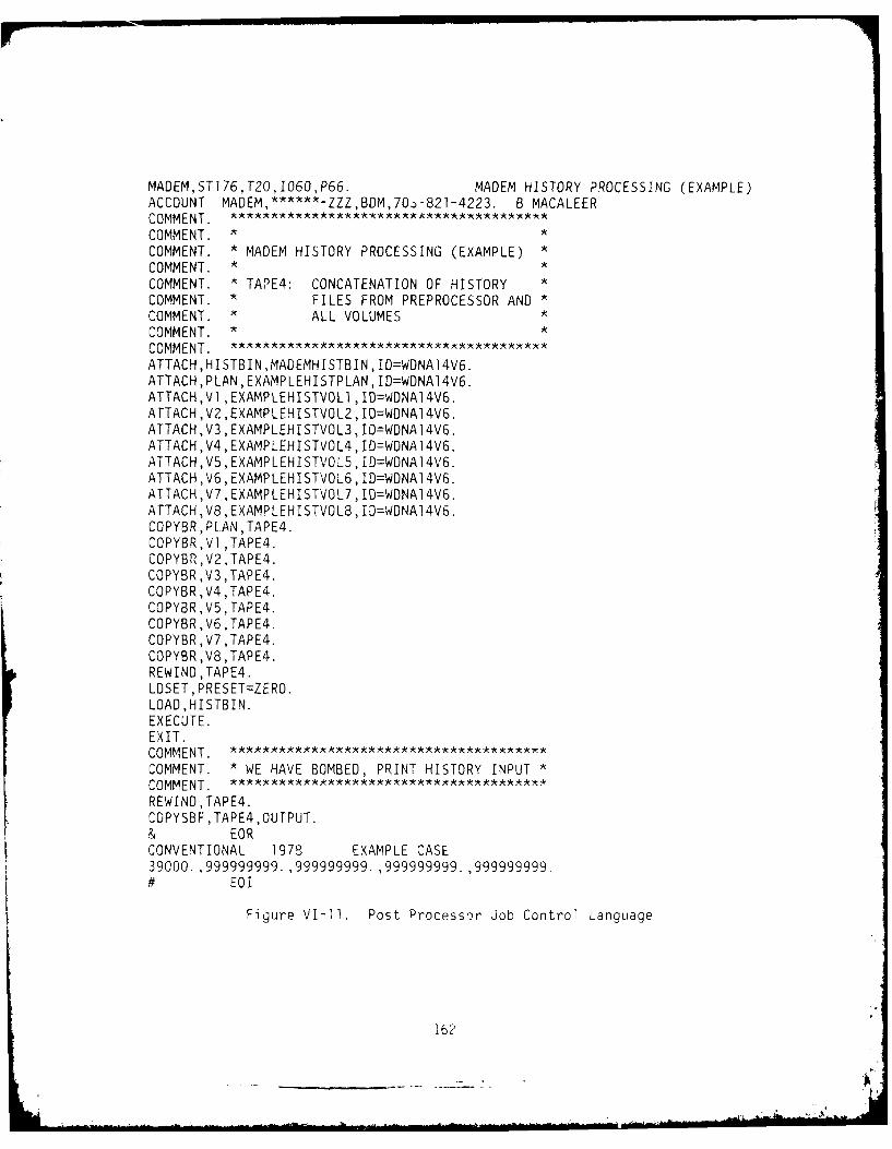
MADEM,ST]76,T20,1060,P66. MADEM HISTORY PROCESSING (EXAMPLE)ACCOUNT MADEM,******-ZZZ,BDM,7.-)-821-4223. B MACALEERCOMMENT.COMMENT.*COMMENT. *MADEM HISTORY PROCESSING (EXAMPLE)COMMENT.**COMMENT. TAPE4: CONCATENATION OF HISTORYCOMMENT. FILES FROM PREPROCESSOR ANDCOMMENT. ' ~ ALL VOLUMES*COMMENT.*COMMENT.ATTACH,HISTBIN ,MADEMHISTBIN, ID=WDNA14V6.ATTACH,PLAN,EXAMPLEHISTPLAN,ID=WDNA14V6.ATTACH,V1 ,EXAMPLEHISTVOL1 ,ID=WDNA14V6.ATTACH ,V2 ,EXAMPLEHISTVOL2, ID=WDNA14V6.ATTACH,V3 ,EXAMPLEHISTVOL3, ID=WDNA]4V6.ATTACH,V4,EXAMPLEHISTVOL4, ID=WDNA14V6.ATTACH,V5,EXAMPLEHISTVOL5,ID=WDNA14V6.ATTACH, V6 ,EXAMPLEHI STVOLS, ID=WDNA1 4V6.ATTACH,V7,EXAMPLEHISTVOL7,ID=WDNA14V6.ATTACH,V8,EXAMPLEHISTVOL8,ID=WDNA14V6.COPYBR ,PL.AN, TAPE4.COPYBR,V1 ,TAPE4.COPYBR ,V2 ,TAPE4.COPYBR ,V3 ,TAPE4.COPYBR,V4,TAPE4.COPYBR ,V5 ,TAPE4.COPYBR,V6 ,TAPE4.COPYBR ,V7 ,TAPE4.COPYBR,V8,TAPE4.REWIND ,TAPE4.LOSET, PRESET=ZERO.LOAD ,HISTBIN.EXECUTE.EXIT.COMMENT.COMMENT. *WE HAVE BOMBED, PRINT HISTORY INPUT*COMMENT.REWIND, APE4.COPYSBF ,TAPE4,OUTPUT.& EORCONVENTIONAL 1978 EXAMPLE CASE39000.,.999999999.,.999999999. .999999999. ,999999999-# EOI
Figure VI-11. Post Processor Job Control Language
162

if only four volumes of the main processor were run, then delete the ATTACH
cards for volumes five thru eight. Once all files are attached, the COPYBR
cards concatenate all the history files into one local file called TAPE4.
Everything after the EXIT card is only executed if the system abnormally
aborts the job stream. In this case, the input (TAPE4) is printed to use
as a debugging tool.
When a run is complete through the post processor, there
will be some permanent files left on the AFWL system that are no longer
needed. These files should be purged using the job control stream that is
listed in Figure VI-12. Again, use only the purge cards corresponding to
the number of volumes that were run.
b. Post Processor Run Parameters
The two cards before the last card are Run Parameter Cards.
The first parameter card is an up to 70 character header that will appear
on the output summary. The second parameter card holds five parameters.
Each of these five parameters represents a time in the simulation when
summary statistics are required. The time is a real number and is in
seconds. In this example we are requesting only one set of summary sta-
tistics, at game time 10.8 hours (39000.0 seconds) which is after the end
of the simulation. Therefore, we will only get final results with no
intermediary statistics. When more than one "snapshot" is requested, the
snapshots are not cumulative; each snapshot covers all events since the
previous snapshot. Up to five snapshots are allowed. If less than five
are needed, it is recommended that dummy values be used (999999999) to
suppress further processing, as was done in this example.
D. OUTPUTS
Each stage of the MADEM simulation produces some useable output. The
preprocessor produces the Red raid plans, the main processor produces an
event trace, and the post processor produces a summary of the events of the
simu1l ation.
163
-- - ---.----.. _________.___ --- ]

MADEM,ST176,T40,104O,P66. PURGE HOLD AND HISTORY FILES (EXAMPLE)ACCOUNT MADEM, ,BDM,703-821-4223. B MACALEERCOMMENT. *****************A*
COMMENT. * PURGE HOLD FILES FOR EXAMPLE RUN *
COMMENT.PURGE,PL1 ,EXAMPLEPLAN1 ,ID=WDNA14V6,LC1l.PURGE,PL2,EXAMPLEPLAN2,ID=WDNA14V6,LC=1.PURGE,VlA,EXAMPLEVOLlA,ID=WDNA14V6,LC=1.PURGE,VlB,EXAMPLEVOLIB,ID=WDNA14V6,LC=1.PURGE,V2A,EXAMPLEVOL2A, ID=WDNA14V6,LC=1.PURGE,V2B,EXAMPLEVOL2B, ID=WONA14V6, LC1l.PURGE,V3A,EXAMPLEVOL3A,ID=WDNA14V6,LC=1.PURGE ,V3B ,EXAMPLEVOL3B, ID=WDNA1 4V6 ,LC=1.PURGE,V4A,EXAMPLEVOL4A,ID=WDNA14V6,LC=1.PURGE,V4B,EXAMPLEVOL4B,ID=WDNA14V6,LC=1.PURGE,V5A,EXAMPLEVOL5A,ID=WDNA14V6,LC=1.PURGE,V5B,EXAMPLEVOL5B,ID=WDNA14V6,LC=1.PURGE,V6A,EXAMPLEVOL6A, ID=WDNA14V6, LC=1.PURGE,V6B,EXAMPLEVOL6B,ID=WDNA14V6,LC=1.PURGE, V7A, EXAMPLE VOL7A, ID=WDNAJ 4V6, LC=1.PURGE,V7B,EXAMPLEVOL7B,ID=WDNA14V6,LC~1.PURGE, V8A ,EXAMPLEVOL8A, ID=WDNA1 4V6, LC1.-PURGE,V8B,EXAMPLEVOL8B,ID=WDNA14V6,LC=1.
COMMENT.COMMENT. * PURGE HISTORY FILES FOR EXAMPLE RUN*COMMENT.PURGE,HP,EXAMPLEHISTPLAN,ID=WONA14V6,LC=1.PURGE,H1 ,EXAMPLEHISTVOL1 ,ID=WDNA14V6,LC1I.PURGE, H2 ,EXAMPLEHISTVOL2, ID=WDNA1 4'6 ,LC=1.PURGE,H3,EXAMPLEHISTVOL3,ID=WDNA14V6,LC=1.PURGE,H4,EXAMPLEHISTVOL4,ID=WDNA14V6,LC=1.PURGE,H5,EXAMPLEHISTVOL5,ID=WONA14V6,LC=1.PURGE,H6,EXAMPLEHISTVOL6,ID=WDNA14V6,LC=1.PURGE,H7,EXAMPLEHISTVOL7,ID=WDNA14V6,LC=l.PURGE,H8,EXAMPLEHISTVOL8,ID=WDNA14V6,LC=1.# EOI
Figure VI'-12. Post Run Purging JCL
164

1. Preprocessor Output
The preprocessor produces three types of printed output: an echo
of the Data Base File, an echo of the User Input Lanaguage File, and a
description of the Red attack plan for raid one. In our example case, the
Red attack consisted of one raid, two waves, as determined by the UOIL
File.
The first part of the red planner output is a list of flight
action codes with their respective descriptions. These codes are used in
the remainder of the output to indicate the movements and actions of each
flight in the wave. These Flight Action Codes are also listed below:
FLIGHT ACTION CODES:
1 JAMMER ON
2 JAMMER OFF
3. PROFILE CHANGE POINT
4. ECM ORBIT
5. INTERCEPT ORBIT
6. RENDEVU POINT
7. GROUND ATTACK ORBIT
8. ASM LAUNCH
9. STOP ORBIT, NEWCOURSE
10. LAND
11. CHANGE COURSE
These actions may be taken at the end of each leg of a flight path.
The rest of the planner output consists of detailed descriptions
of each wave in raid one, beginning with the last wave. For each target of
the Red attack, its hex location is given with a description of the flight
plans for each formation assigned to the target. There is one line of
output for each action taken by each flight. There are twelve fields on
each line of output (repetition is implied with blank fields). These
fields are described below:
(1) Target Type - Numeric code indicating the type of
target. See Appendix E for an expla-
nation of the codes.
165
,6,1'

(2) Target Unit Number Unit number of a specific target. These
unit numbers are derived from the UOIL
File. If the unit number is negative,
that means the target is passive.
(3) Target Location - Hex location of the target.
(4) Formation Type - Type of formation assigned to the tar-
get. These formation types are defined
by the data base file.
(5) Flight Unit Number - Unit number of a flight in the forma-
tion. These unit numbers are created by
the simulation.
(6) Flight Type - Indicates the type of flight as defined
by the Data Base File.
(7) Number of Aircraft - Indicates how many aircraft are in the
flight.
(8) Aircraft Type - Numeric code indicating the type of
aircraft in the flight. All fli-ghts are
homogeneous. See Appendix E for an
explanation of the codes.
(9) Airbase Unit Number - Unit number of the airbase that the
flight originated from. This number
comes from the UOIL File.
(10) Airbase Location - Hex location of the airbase that the
flight originated from.
(11) Action Hex - Hex location at which the action des-
cribed in the next field is to take
place.
(12) Action Code - Action codes, described in the first
page of planner output, that describes
flight movements at the given hex loca-
tions.
166

a. First Wave Attack Plan
The first wave attack plan which results from the first wave
attack specification input by the user is summarized and output by thepreprocessor. The first wave plan for this scenario output by the pre-
processor is shown in figure VI-13. The assignment of flights from various
airbases to formations and subsequently to blue targets is output along
with the flight plans for each flight.
The first wave attack plan shown in figure VI-13 is illus-
trated in figure VI-14. Figure VI-14 shows the courses to target planned
for the first wave. These courses indicate planned attacks on HAWK andNike-Hercules batteries in the attack corridors.
b. Second Wave Attack Plan
A partial listing of the second wave attack plan output isshown in figure VI-15. The same plan is illustrated in figure VI-16. Both
figures indicate planned attacks on HAWK batteries near the attack cor-
ridors and upon airbases and passive targets deep in blue airspace.
Several large. formation rendevous points are also indicated within red
airspace.
2. Main Processor Output
The main processor produces a printed event trace while the
simulation is in progress. Only pertinent events produce an event trace.
Since about ninety percent of the simulation events are trival (but
necessary) only about one event in ten produces a printed trace.
The event trace messages are explained in Appendix B. To theleft of each event message is the game time, in seconds, at which the event
occurred. See figure VI-17 for a sample event trace.
3. Post Processor Output
The MADEM postprocessor outputs a variety of information designed
to aid analysts in computing measures of air defense effectiveness. These
outputs are in the form of tables which contain the following information:
(1) Units created by type
(2) Red attacks on Blue players by aircraft type
167
,ai

lU ~ ~ ~ ~ ~ ~ ~ ~ ~ ~ ~ ~ ~ ~ ~ ~ ~ ~ ~ ~ . ..0 .....~0'0~ -~ 0'0~T-~l0'0~I ~l0'0C'! 0'0' -(
r- Z
a- 74-.
.0 enc c
-ena -w n C
0l Lncl
a) coc
(Za a. 4cJ
10168

'Ao
4368179
FigreVI-4. Firt aveAtac PlSOan t
1695

-C
<z -- - - - -
<' ('4 044 -
XC - w0c-T NO~ ('4 (' N
CC
CL)n
C1 0

o ~"-'w I
7 R
ofa :0C
2 SS-tAQ
4 3 68/179WVFgr 6 eodWv takPa
171

3L - L. __j
Tr Cr) Cr) 0l LA- 0L (= - 04CY C1 C, C) -4 0 -: .V - b-j LL. 0L 7 )=C)=C4L- a
o0 4.- 0(0 ( 0DC)" C 4aI-j CV -4- -i -= cm m m
U-- -j =~ U-) U- = LL
U- CI 0)1 CZ Z(JU -O)-D C C .-- 4~~ OC'. 0C\JLAU L-
L. LL- U- C) LL LU r LL. - 1- La- 1L-q= r U- -0 = ( U aia)
CY LU 14 -4U-n U- = M~ --
LL en M >- 0 >->->
00 C) C= CC CC~ 0x C 000CCLL. LU. (D) LA-> ) - C ) L -LL A
00 =- C) 0 ) C) 000 =- =
4 UA- -r.U- - 4-L-- J 0" UAC) - A- U- U- U-U- -j
(A (.0 en C Z'V)C (-)( C) 4L AAA() 0(
L-' 0L L U .AJ O O4 -. oL -0k0W
CZ C- >L.)U-IA> (AIO LZ 0L L >~ A AC- LU ) ta)a
CD 0 - M- -(=I- Im 1LULULUU1- M 1- 0-LU Ln >--. L -0 LO L- LA >-LO0 -L -(.-nL L
0~ F- - L L uuLUJ kD a C) LO ==0 0 ar)"
CD - 1- -
()~a LA L.C
~J, ~)C) CD)
Zn 4?) ff) 0C) C C) ll m-L
"i (.J (-4 m-4 f) c.J U
u LA u A V C-)LALA < - <- -T-
0n 1.0 00 LAcA
LA ( Lr C-) C-) (NN)L
172

(3) Red attacks on Blue passive targets by aircraft type
(4) Acquisitions of Red flights by blue units
(5) Red flights engaged by Blue defense units
(6) Red aircraft killed by Blue defense units
(7) Missiles fired by unit type
These table are displayed in three formats. The first format is used only
for units created and is illustrated in Figure VI-18. The second format
type is used for Red attacks on Blue players, Red attacks on Blue passive
targets, and Red aircraft killed by Blue defense units. This format is
illustrated in figure VI-17. The "231" in the uper left hand corner of the
output matrix in Figure VI-19 is an internal matrix code number. It can be
ignored in the analysis of MADEM output. Column I and Row I of the matrix
in Figure VI-19 indicate the unit code numbers of attacking red flights and
defending Blue units respectively.
Figure VI-20 illustrates the format used to display acquisitions
of Red flights by Blue units, Red flights engaged by Blue units,and
missiles fired. This format is identical to figure VI-19 except for the
addition of row and column totals indicated by a 9999 in Row 1 and Column
1.
173

TYPE NUMBER34 1130 2150 2160 2170 6180 4210 4220 8401 12420 11440 16460 11
NOTE: SEE APPENDIX E FOR UNIT CODE DEFINITIONS
Figure VI-18. Number Of Units Created By Type
174
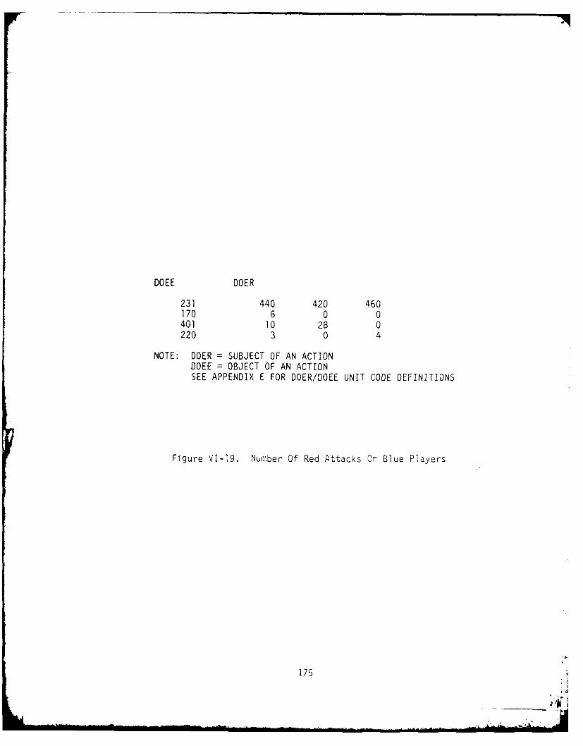
DOEE DOER
231 440 420 460170 6 0 0401 10 28 0220 3 0 4
NOTE: DOER = SUBJECT OF AN ACTIONDOEE = OBJECT OF AN ACTIONSEE APPENDIX E FOR DOER/DOEE UNIT CODE DEFINITIONS
Figure VI-19. Number Of Red Attacks On Blue Players
175
-A -- ,!

en - - -)(
Q4)
oc
-p-
LUAcm4
U.1 C
-UaZL
C)~
cc wiLL
C\J
(7% ~ .~ LDL A p U- 0 3:a) m LL LA- C:
C)~ ~ C -) cm --cm ~ - an = C
i C) L~iU
W LLa
C) C)W Ua
LLU
176

APPENDIX A
USER GUIDE TO HEXAGONAL COORDINATE SYSTEM
A. INTRODUCTION
The purpose of this appendix is to give a brief explanation of the
Hexagonal Coordinate System (HECS) used in MADEM. For a more detailed
discussion, including the rationale for using this coordinate system, the
reader is referred to the draft technical report, "An Integrated Coordinate
System for Combat Modeling", BDM/W-78-297-TR, 19 May 1978.
B. STRUCTURE OF HECS
The Hexagonal Coordinate System is based upon the concept of tiling
the plane with a grid of regular hexagons and aggregating them into suc-
cessivel, larger clusters of 7. A single regular hexagon in the grid is
called a level 0 hex. A cluster of 7 level 0 hexes, one regular hexagon
together with its 6 neighboring hexagons, is called a level 1 hex. This
process of aggregation can be iterated, and in general a cluster of 6 level
n hexes surrounding a central level n hex forms a level n + 1 hex.
The higher level hexes are not true regular hexagons, but they remain
approximately hexagonal in shape. Hexes at any level mesh together to tile
the plane.
C. MADEM AIRSPACE
The MADEM airspace is represented by a single level 12 hex. This hex
contains 7 level 11 hexes, each of which contains 7 level 10 hexes, and so
on down to the level 0 hexes, which are regular hexagons. The grid is
oriented so that the level 0 hexes have a pair of opposite edges running
west to east. The lowest level Hex used in MADEM is a level 6 Hex which
measures 9.45km from face to face. Each unit (including Flights) is
located in a level 6 Hex.
177 !

HEX LEVEL NO. OF HEX DIAMETER HEX AREA
DEC OCT HEX DIGITS (KM) D2 \fTT13 15 0 8575. 63,700,000
12 14 1 3240. 9,100,000
11 13 2 1225. 1,300,000
10 12 3 463. 185,600
9 11 4 175. 26,500
8 10 5 66.1 3,790
7 7 6 25. 541
6 6 7 9.45 77
Figure A-i. Hex Specifications
178

D. HEX ADDRESSES
A hex address is a string of one to twelve digits which identifies a
specific hex. It is a way of encoding both the location and the level of a
hex. Each digit in a hex address is from 1 through 7 inclusive. The
leftmost digit identifies which of the 7 level 11 hexes contains this hex.
If there are no further digits, then the hex address corresponds to this
level 11 hex. The next digit identifies which of the 7 level 10 hexes
comprising the level 11 hex contains the hex in question. This classifi-
cation procedure continues all the way down to the level of the specificed
hex. The hex address of a level 0 hex will have 12 digits, and in general
the following equation is satisfied:
L + D =12
where L is the level of the hex and D is the number of digits in its hex
address.
The numbering scheme for a level 7 cluster of 7 level 6 hexes is shown
in Figure A-2. Note that 7 indicates the center hex and 1 indicates the
hex directly north of center. The rest of the numbering scheme is chosen
for computational convenience. The numbering scheme for a level 8 cluster
of 7 level 7 hexes is shown in A-3. The scheme is essentially the same
except that there has been a slight counterclockwise rotation of the posi-
tions of the hexes numbered 1 through 6. For clusters of higher and higher
level hexes, the same numbering scheme is used, but the relative positions
of the outer hexes rotate approximately 19 degrees counterclockwise for
each increase in level.
Figure A-4 illustrates the combined numbering scheme for level 6 hexe-
within a level 8 hex. The two digits shown would be the last 2 digits in
the hex addresses for these level 6 hexes. Note that the shaded level 6
hex is numbered 35 because it is in the 5 position within the number 3
level 7 hex in the level 8 cluster. Figure A-5 shows a few sample hex
179
.. . . .. .. . . . . . .. ... .. . .. ..... .. . .. . . .. . . ....,£ , S,,, 4-
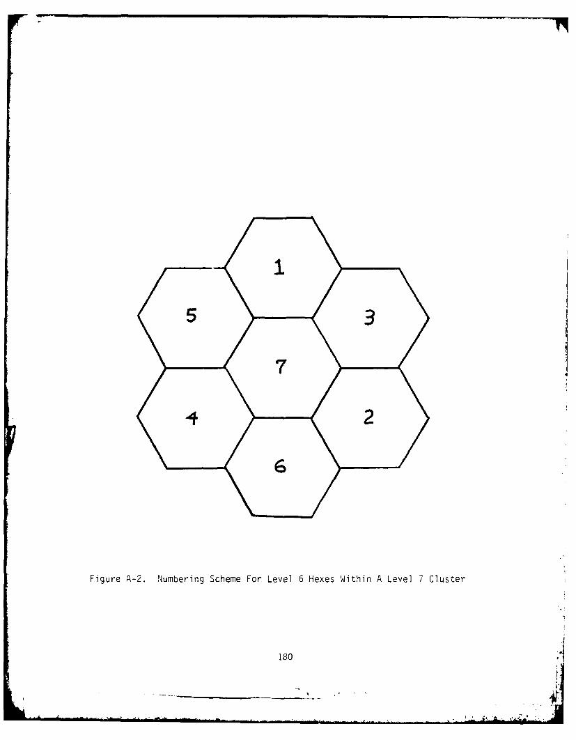
wI
Figure A-2. Numbering Scheme For Level 6 Hexes Within A Level 7 Cluster
180A

Figure A-3. Numbering Scheme For Level 1 Hexes Within A Level 2 Cluster
181

Figure A-4. Combined Numbering Scheme For Level 6 Hexes
Within A Level 8 Cluster
S182

7 Y3
Figure A-5. Sample Hex Addresses Within a Level 9 Cluster
1 83
- -. ".

addresses in a level 9 cluster. Actually each address would be preceded by
a digit identifying the particular level 9 hex illustrated.
E. HEX DIRECTIONS
Movement is always in the direction of one of the six surrounding
hexes of the same level. The directions are identified by the same
numbering scheme as used for creating hex addresses. Thus, at each level,
the hex direction 7 represents a null direction signifying no movement, and
there are 6 equally spaced hex directions numbered I through 6. A level 0,
hex direction I corresponds to north, but it undergoes a counterclockwise
rotation of about 19 degrees for each higher level. Figures A-6 and A-7
illustrate the hex directions at levels 6 and 7.
184

NNNW NNE
NW NE
WNW .. ,ENE
2
6W \ E
WSW/ "E SE
ww SE
SSW SSES
Figure A-6. Hex Directions At Level 6
185
- - -_ _ _ ...._ - :-. S

N
NW N
W E
SSW SSES
Figure A-7. Hex Directions At Level 7
186

APPENDIX B
MADEM DISPLAYED EVENTS
As events occur in the model a message will be printed to symbolize
what is happening in the model. These event messages originate out of the
subroutines. The variable numbers that are printed out in the message are
denoted here by *NO.
The following is a list of the event messages and the subroutines
associated with it. In the list below, the Source column shows the
initiator of the event and is the key to the format of the event message
print out. The events are printed in three columns: the first column is
the Red, the second is the CRC/AB and the third is the BOC/BTRY.
Subroutine Source Message
AB2CRC CRC/AB CRC *NO ACKS LAUNCH OF INT *NO
CRC/AB CRC *NO ACKS LANDING OF INT *NO
ABSEE CRC/AB A/B *NO ACKS LANDING REQUEST FROM INT *NO
CRC/AB A/B *NO ACKS REQUEST FOR INTERCEPTORS BY *NO
ACCEPT BOC/BTRY UNIT *NO PLACES FLIGHT *NO ON FOQ
BOC/BTRY UNIT *NO RECEIVES ORDER TO ENGAGE FLIGHT*NO WITH *NO FIRE UNITS
AIRTHNK RED FLT *NO TYPE * NO ENGAGES *NO
CRC/AB INT *NO ENGAGE *NO RELEASING *NO
ALLOBAT BOC/BTRY BTN *NO ASSIGNING BATTERY ANO *NO ("NO)
UNITS OF COVERAGE ON FLIGHT *NO
BOC/BTRY BTN *NO PLACES FLIGHT *NO ON PDIL
187
- : A .

Subroutine Source Message
ALLOFU BOC/BTRY FIRE UNIT *NO OF BTRY *NO ASSIGNED TO FLIGHT*NO
ALLOPAT BOC/BTRY BTRY *NO TAKES ENG *NO (*NO) AGAINST FLT*NO
AMMOCHK BOC/BTRY BATTERY *NO: FIREUNIT *NO EMPTY
ATKASES RED FLT *NO DESTROYS TGT *NO TYPE *NO
RED FLT *NO REPORTS *NO TYPE AND HAS *NO DAMAGE
RED FLT *NO WILL BE SHOT FOR MISSING *NO TYPE
*NO
BNCONHD BOC/BTRY BTN *NO PONDERS HEADING CHANGE BY FLIGHT*NO
BNCONTC BOC/BTRY BTN *NO PLACES FLIGHT *NO ON PDIL
BNNOTRD BOC/BTRY BTN *NO NOW IMPOTENT
BNPONBB BOC/STRY BTN *NO WELCOMES ABOARD BTRY
BNPONBD BOC/BTRY BTN *NO MOURNS THE UNTIMELY DEATH OF BATTERY
(*NO)
BNPONFA BOC/BTRY BTN *NO SAVORS THE DEATH OF *NO A/C IN FLIGHT*NO
BNPONFD BOC/BTRY BTN *NO CELEBRATES TOTAL ANNIHILATION OF
FLIGHT *NO
188 t.

Subroutine Source Message
BOCTINK BOC/BTRY BTN *NO GIVES UP ON FLIGHT *NO
BTNASIN CRC/AB CRC *NO ASSIGNS *NO TO BTN *NO
BTN2CRC CRC/AB CRC *NO ACKS RLSE OF TGT *NO BY BTN *NO
CRC/AB CRC *NO ACKS DEATH APT ON *NO BY BTN *NO
CRC/AB CRC *NO ACKS LOSS OF TGT TRK *NO BY BTN *NO
BTRYTNK BOC/BTRY BATTERY *NO GIVES UP ON FLIGHT *NO
BOC/BTRY BTRY *NO LOSES TRACK *NO (MASK = *NO)
BYALCOV BOC/BTRY BTRY *NO NOW TO COVER FLIGHT *NO WITH *NO
FIRE UNITS
BYCMDPR BOC/BTRY BTRY *NO RELEIVES CEASE ORDER FOR FLIGHT *NO
BYCONHD BOC/BTRY BATTERY *NO PONDERS HEAnING CHANGE BY FLIGHT*NO
BYNOTRD BOC/BTRY BATTERY *NO AWAITING RELOAD
BYPONRL BOC/BTRY BTRY *NO: FIRE UNIT *NO LOADED *NO TYPE *NO
MISSILES
BYPONRS BOC/BTRY BTRY *NO RESUPPLIED -- *NO MISSLES
BYPONTM BOC/BTRY FLIGHT *NO TRACKED BY BATTERY *NO
CANCALO BOC/BTRY FIRE UNIT *NO OF BTRY *NO CEASES FIRE ON
FLIGHT *NO
BOC/BTRY BTRY *NO CEASES ONE ENGAGEMENT OF PL7 *NC
(*NO)
189
AD-AL07 915 SON CORP MCLEAN VA F/6 15/3MODULAR A IR DEFENSE EFFECTIVENESS MODEL, PROBRAM DOCUMENTATION -ETC(U)JAN 80 M FILTEAU, B MACALEER, J T HAWKINS DNAOO-79C-0203
UNCLASSIFIED BDM/W-79-646-TR-VOL-1 DNA-SSSAF- 1 L

Subroutine Source Message
CHKCOV RED POSSIBILITY --- *NO
COMMAND RED FLT *NO TYPE *NO DIVES TO *NO METERS
RED FLT *NO TYPE *NO CLIMBS TO *NO METERS
RED FLT *NO TYPE *NO AT RENDEZVOUS POINT
RED FLT *NO TYPE *NO STRT GND ATK ORB IN *NO
RED FLT *NO TYPE *NO REQUEST LANDING AT *NO
RED FLT *NO TYPE *NO HEADS FOR HEX *NO
CRC21NT CRC/AB INT *NO ACKS RTN TO A/B ORDR FRM CRC *NO
CRC/AB INT *NO ACCEPTS TARGET *NO
CRC/AB INT *NO REJECTS ASSIGNMENT OF TARGET *NO BY
CRC *NO
CRC/AB INT *NO ACKS NEW INTERCEPT VECTOR
CRC/AB INT *NO ACKS BREAKOFF MSG FOR TARGET *NO
CRCKIL CRC/AB CRC *NO PONDERS DEATH OF *NO
CRC/AB CRC *NO PONDERS DEATH OF INT *NO
CRC/AB CRC *NO MARKS TGT *NO UNASSIGNED
CRCEVNT CRC/AB CRC *NO DETECTS DEATH OF *NO
CRC/AB CRC *NO ACQUIRES FLT *NO
CRC/AB CRC *NO LOSES FLT *NO
CRCTRAK CRC/AB CRC *NO SCRAMBLES INTERCEPTORS AT ALL A/B
CRC/AB CRC *NO CORRECTS MISID OF *NO
DECRALO BOC/BTRY BTN *NO ORDERS BTRY *NO TO REDUCE
DESTROY RED XXXXXXXXXXXXXXXXXX UNIT *NO IS DEAD
XXXXXXXXXXXXX
190
_ _ _ _ _ _ _
'4 -.
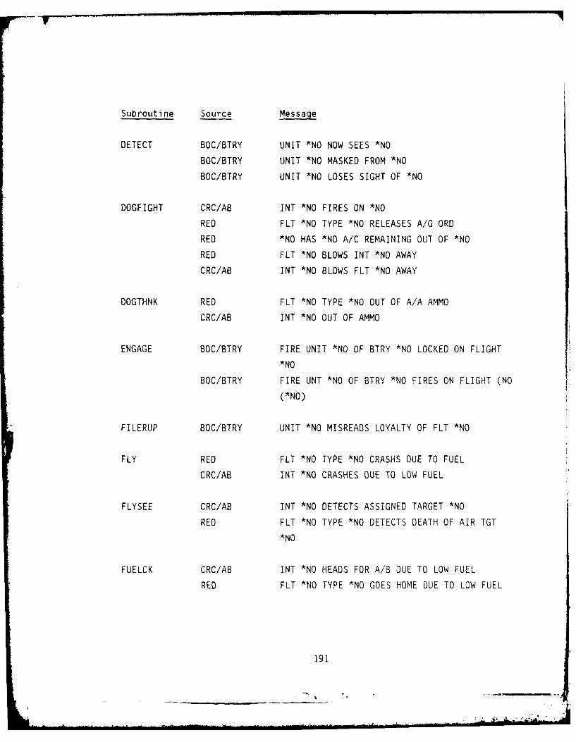
Subroutine Source Message
DETECT BOC/BTRY UNIT *NO NOW SEES *NO
BOC/BTRY UNIT *NO MASKED FROM *NO
BOC/BTRY UNIT *NO LOSES SIGHT OF *NO
DOGFIGHT CRC/AB INT *NO FIRES ON *NO
RED FLT *NO TYPE *NO RELEASES A/G ORD
RED *NO HAS *NO A/C REMAINING OUT OF *NO
RED FLT *NO BLOWS INT *NO AWAY
CRC/AB INT *NO BLOWS FLT *NO AWAY
DOGTHNK RED FLT *NO TYPE *NO OUT OF A/A AMMO
CRC/AB INT *NO OUT OF AMMO
ENGAGE BOC/BTRY FIRE UNIT *NO OF BTRY *NO LOCKED ON FLIGHT
*NO
BOC/BTRY FIRE UNT *NO OF BTRY *NO FIRES ON FLIGHT (NO
(*NO)
FILERUP BOC/BTRY UNIT *NO MISREADS LOYALTY OF FLT *NO
FLY RED FLT *NO TYPE *NO CRASHS DUE TO FUEL
CRC/AB INT *NO CRASHES DUE TO LOW FUEL
FLYSEE CRC/AB INT *NO DETECTS ASSIGNED TARGET *NO
RED FLT *NO TYPE *NO DETECTS DEATH OF AIR TGT
*NO
FUELCK CRC/AB INT *NO HEADS FOR A/B DUE TO LOW FUEL
RED FLT *NO TYPE *NO GOES HOME DUE TO LOW FUEL
191

Subroutine Source Message
GNDLOOK RED FLT *NO DETECTS GND TGT *NO
RED FLT *NO OVERLOOKS GND TGT *NO IN *NO
RED FLT *NO DISCOVERS TGT *NO NOT IN *NO
RED FLT *NO TYPE *NO ABORTS GROUND ATTACK
GOGETEM CRC/AB A/B *NO LAUNCHS INTRCPTR *NO
INT2CRC CRC/AB CRC *NO ACKS INT *NO AVAIL - DEAD TARGET *NO
CRC/AB CRC *NO ACKS INT *NO AWATTING ORDERS
CRC/AB CRC *NO ACKS ACQUISITION BY INT *NO OF TARGET
*NO
CRC/AB CRC *NO ACKS NONAVAIL MSG FRM INT *NO
CRC/AB CRC *NO ACKS MISID OF TGT *NO
CRC/AB CRC *NO ACKS REFUSAL OF TGT *NO BY INT *NO
INTASIN CRC/AB CRC *NO ASSIGNS *NO AGAINST *NO
CRC/AB CRC *NO SCRAMBLES INTERCEPTRS AT A/B *NO
INTFIND RED FLIGHT *NO DETECTS ASSIGNED TGT *NO AT TIME
*NO
INTRFLY CRC/AB INT *NO REQUESTS LANDING FROM A/B *NO
CRC/AB INT *NO RETURNS TO A/B *NO FOR CAP
NEWMOVE CRC/AB CRC *NO MISTAKES IFF OF *NO SIDE *NO
NUKBLND RED ++++++.+.+++. + UNIT *NO COMMO IS DEAD +++.+
READIL BOC/BTRY BTN *NO RETURNING FLIGHT *NO TO ADIL
192
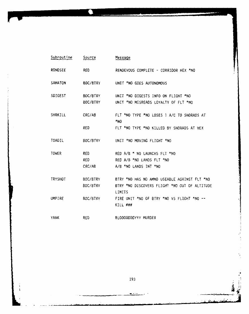
Subroutine Source Message
RONDSEE RED RENDEVOUS COMPLETE - CORRIDOR HEX *NO
SAMATON BOC/BTRY UNIT *NO GOES AUTONOMOUS
SOIGEST BOC/BTRY UNIT *NO DIGESTS INFO ON FLIGHT *NO
BOC/BTRY UNIT *NO MISREADS LOYALTY OF FLT *NO
SHRKILL CRC/AB FLT *NO TYPE *NO LOSES I A/C TO SHORADS AT
*NO
RED FLT *NO TYPE *NO KILLED BY SHORADS AT HEX
TOADIL BOC/BTRY UNIT *NO MOVING FLIGHT *NO
TOWER RED RED A/B * NO LAUNCHS FLT *NO
RED RED A/B *NO LANDS FLT *NO
CRC/AB A/B *NO LANDS INT *NO
TRYSHOT BOC/BTRY BTRY *NO HAS NO AMMO USEABLE AGAINST FLT *NO
BOC/BTRY BTRY *NO DISCOVERS FLIGHT *NO OUT OF ALTITUDE
LIMITS
UMPIRE BOC/BTRY FIRE UNIT *NO OF BTRY *NO VS FLIGHT *NO
KILL ###
YANK RED BLOOOODDDYYY MURDER
193
- *41

APPENDIX C
COMMAND AND CONTROL MESSAGE LIST
Communication events are the sending of messages from one player to
another. These messages originate in the subroutines. There is a code
number associated with each message type.
The following is a list of the messages and the subroutines they occur
in. The message is not printed out in this form, it is the interpretation
of it. For a list of the event messages printed as output see Appendix B.
Event No. Code Subroutine Message
25650001 1320 AIRTHNK Schedule msg. to live CRC of availability
25690001 1320 AIRTHNK Report from interceptor to CRC that
interceptor is goint to engage a target
of opportunity
25690001 2831 ALLOBAT Order from BOC to BTRY to attempt to
engage a particular flight
25690001 2834 ALLOBAT Order from BOC to BTRY increasing
assigned coverage leve; against a
particular flight
25340001 2751 AMMOCK Report from BTRY to BOC that assigned
flight can no longer be engaged due to
lack of appropriate type of ammo
25690001 1500 BADMOVE Schedule breakoff message to interceptor
PMWIN PAMX BLAW-gOT FIOA
t195
L .f..

Event No. Code Subroutine Message
256900C 1520 BADMOVE Update from CRC to interceptor on course
of assigned flight
25690001 2635 BNCONHD Update from BOC to BTRY on course of
assigned flight
25690001 1600 BNCONLS Report from BOC to CRC that assigned
flight has been lost to sight
25690001 1600 BNCMDPR Report from BOC to CRC indicating
assignment cannot be accepted because
no assets ready for action
25690001 2761 BNLALLE Report from BOC to CRC, or from BTRY
to BOC, indicating no projected oppor-
tunity to engage assigned flight
25690001 2832 BNPONEP Order to BTRY to cease fire on a partic-
ular flight
25690001 1600 BOCTINK Report from BOC to CRC that assigned
flight was not sighted
25120001 2731 BTNASIN Order from CRC to BOC to attempt to
engage a particular flight
25690001 2762 BTRYTNK Report from BTRY to BOC that assigned
flight was not sighted as expected
196

Event No. Code Subroutine Message
25690001 2762 BYCONLS Report from BTRY to BOC that assigned
flight has been lost to sight
25690001 2762 BYCONTL Report from BTRY to BOC that assigned
flight has changed course
25690001 2761 BYHEDUP Report from BTRY to BOC that BTRY no
longer has a projected opportunity to
engage an assigned flight
25690001 2762 BYNWTRK Report from BTRY to BOC that assigned
flight was changed course
25690001 2780 BYPONER Report from BTRY to BOC on attrition of
assigned flight
25690001 2790 BYPONFD Report from BTRY to BOC on total destruc-
tion of flight
25690001 2752 BYPONRL Report from BTRY to BOC on ammo reload
25390001 1984 COMMAND Landing request from aircraft to airbase
25690001 1310 CRC2INT Report from interceptor to CRC that
interceptor is available for assignment
25650001 1330 CRC2INT Schedule msg to CRC can't accept
assignment
25650001 1312 CRCTRAK Order from CRC to airbase to scramble
interceptors
197
* L II I--
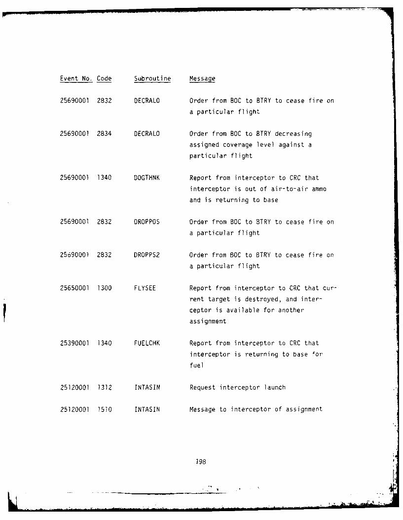
Event No. Code Subroutine Message
25690001 2832 DECRALO Order from BOC to BTRY to cease fire on
a particular flight
25690001 2834 DECRALO Order from BOC to BTRY decreasing
assigned coverage level against a
particular flight
25690001 1340 DOGTHNK Report from interceptor to CRC that
interceptor is out of air-to-air ammo
and is returning to base
25690001 2832 DROPPOS Order from BOC to BTRY to cease fire on
a particular flight
25690001 2832 DROPPS2 Order from BOC to BTRY to cease fire on
a particular flight
25650001 1300 FLYSEE Report from interceptor to CRC that cur-
rent target is destroyed, and inter-
ceptor is available for another
assignment
25390001 1340 FUELCHK Report from interceptor to CRC that
interceptor is returning to base for
fuel
25120001 1312 INTASIN Request interceptor launch
25120001 1510 INTASIN Message to interceptor of assignment
198
1

Event No. Code Subroutine Message
25620001 1330 INTFIND Message to CRC reporting direction
25390001 1310 INTERFLY Request orders from CRC
25390001 1984 INTRFLY Landing request from interceptor to
airbase
199

APPENDIX D
THE AFWL SYSTEM
MADEM uses either of 2 computers at AFWL, the Y mainframe (MFY) or the
X mainframe (MFX). Both are CDC Cyber 176 machines. We generally run on
MFY since our remote terminal has a direct line there, but we can run on
either. It is possible to use a dial up terminal for either batch or
interactive service using the following phone numbers.
BAUD RATE MFY MFX
300 505-264-2082(3) 505-842-5162 (17)
300 -- 505-842-9980 (10)
300 -- 505-264-5875 (3)
300 -- 505-264-9861 (3)
1200 505-264-5840 (3) 505-264-5705 (3)
4800 505-264-7812 (3) --
4800 505-842-6392 (2) 505-842-6391 (4)
4800 -- 505-842-5711 (6)
The number in parenthesis is the number of lines on that rotary. MADEM
cannot run on MFB because of the extended core requirements of MADEM.
1. AFWL Operating System
AFWL runs on the NOS/BE 1.2 operating system. The correct manual
for this operating system is the CDC manual 60493800.
Intercom 4.1 is the operating system that interfaces remote
terminals (batch or interactive) with the mainframes. Ths manual for this
is the CDC manual 60494600.
2. Using AFWL from BDM - Washington
We have a data 100 remote batch terminal that has a direct line
(4800 BAUD) to AFWL's MFY. We can also dial up from another terminal, but
we generally use the Data 100.
201 , ]
- jX. 2-

a. Using the Data 100
To bring up the Data 100:
1. Load Emulator - Read in "DATA 100" cards by pressing
"HALT", then "LOAD". After cards have been read press
"RUN".
2. Press XMIT button - XMIT light on is for 029 keypunch.3. Wait for "DATA LINK" light.
4. Before entering each command, press Control-A.
5. Type "LOGIN, SGCBDM, WDNAI4V6, SUP"
6. Wait for "COMMAND" message.
7. Type "C".
To Enter Cards:
1. Load cards.
2. Press START
3. Type "R" when reader stops.
To turn on line printer type "ON,LP".
3. AFWL JCL Notes
a. AFWL Job Card
The first card in a JCL deck is a job card.
Example: MADEM, ST176, T40, 1037, P66.
MADEM - can be any name, first five characters used as
first five characters of seven character job name.
ST176 - Tells it to run on either Cyber 176 (MFY or MFX).
Can also use STMFX of STMFY to run on a particular
machine.
T40 - CPU time limit in octal seconds.
1037 - 10 time limit in octal seconds.
P66 - Request for 66 priority. The highest priority
allowed. The priority is dependent on 10 and CPU
time requested.
202

P66 I0+CPU is less than 100 octal
P60 IO+CPU is less than 400 octal
P50 IO+CPU is less than 1,000 octal
P40 none
P30 CP is less than 1000B
P20 CP is less than 2000B
PIO CP is less than 40008
b. AFWL Account Card
The second card in a JCL deck is the account card.
Example: ACCOUNT MADEM, XXXXXXXX-ZZZ, BDM,703-821-4223.
ACCOUNT - Card identifier
MADEM - means nothing, can be any name.
XXXXXXXX account ID
ZZZ - account password.
BDM - not needed, but it identifies us.
703-821-4223 - not needed, but enables us to be reached by
this phone number in case a problem occurs.
c. End-of-Record Cards
To separate the JCL from the INPUT File, or to separate two
INPUT Files, use an End-of-Record (EOR) card. The EOR card is a multi-
punch 7/8/9 in column one. When submitting jobs interactively, the system
will interpret *EOR as an EOR card. In some of our JCL examples in this
manual, an EOR card is represented by a '& in column one.
d. End-of-information Cards
At the end of an entire input stream (that is, JCL and any
INPUT Files) use an End-of-Information (EOI) card. The EOI card is a
multi-punch 6/7/8/9 in column one. When submitting jobs interactively, the
system will interpret *EOI as an EOI card. In some of the JCL examples in
this manual, the EOI card is represented by a # in column one.
4. Large Permanent Files at AFWL
Any permanent file larger than 35 RB's (1960 PRU's) will be
routinely purged at AFWL.
203

1 PRU = 64 words
1 RB = 56 PRU's (3,584 words)
35 RB's = 125,440 words
Theoretically, one can have a large perm file saved at AFWL if it is
approved by Airman Vickers. To have a perm file over 35 RB's saved at AFWL
write to:
Airman Richard Vickers
AFWL/ADPO
Kirtland AFB
New Mexico 87117
(505-264-7984)
With the following information:
1. Justification for the large file.
2. How long the file is to be saved.
3. The name of the file.
4. Your account ID.
5. The cycle numbers of that file to be protected.
204

APPENDIX E
VALID PLAYERS AND TARGETS
MADEM is a simulation that interacts with entities within the model.
These entities are in two catagories: active players and passive targets.
The valid players are the ones that can be acted upon or react. A passive
target can only be acted upon, such as targets that can not defend them-
selves. The following is a list of each category and the internal code
used to represent it in the model.
Active Players
Name Code
AIRBASE 220
ATAF 128
AWACS 132
CRC 130
HAWKBOC 150
HAWKBTRY 170
HERCBOC 160
HERCBTRY 180
PATBOC 155
PATBTRY 175
SOC 153
Aircraft Flights
Name Code
BLUE INTERCEPTORS 401-419
RED FIGHTERS 420-439
RED FIGHTER/BOMBER 440-459
RED BOMBERS 460-478
205

Passive Targets
Name Code
ASP 87
BRIDGE 39
CLVBTRY 94
CORPCP 95
0EPOS 40
DIVCP 92
HJ 34
LANCE 86
PERSHING 83
POL 84
RESERVES 88
SASP 210
TAB 158
TRAINS 89
VIIIBTRY 90
Special case
Name Code
SHORAD
COLUMN/ROW TOTAL 9999
206

DISTRIBUTION LIST
DEPARTMENT OF DEFENSE DEPARTMENT OF DEFENSE (Continued)
Armed Forces Staff College Joint Strat Tgt Planning StaffATTN: Reference & Technical Svcs Br ATTN: JL
ATTN: JLAAssistant Secretary of Defense ATTN: JPInternational Security Affairs 2 cy ATTN: JLTW-2
ATTN: European & NATO AffairsATTN: Policy Plans & NSC Affairs Director
NET AssessmentAssistant Secretary of Defense Office of the Secretary of DefenseComm, Cmd, Cont & Intell ATTN: Military Assistants
ATTN: Surveillance & Warning SysU.S. European Command
Assistant to the Secretary of Defense ATTN: J-2Atomic Energy ATTN: J-3
ATTN: Executive Assistant ATTN: J-LWATTN: J-5NPG
Commander-in-Chief, Atlantic ATTN: J-6ATTN: N-22 ATTN: J-2-LTD
Commander-in-Chief, Pacific U.S. National Military RepresentativeATTN: J-634 SHAPEATTN: J-54 ATTN: U.S. Documents OfficerATTN: J-32
Under Secretary of Defense for Rsch & EngrgDefense Intelligence Agency ATTN: Strategic & Space Sys (OS)
ATTN: DIA/VPA-2, Fed Res Div ATTN: Tactical Warfare ProgramsATTN: DB-6
5 cy ATTN: 0B-4 DEPARTMENT OF THE ARMY
Defense Nuclear Agency Deputy Chief of Staff for Ops & PlansATTN: STNA Department of the ArmyATTN: NATD ATTN: DAMO-ZXAATTN: NATA ATTN: DAMO-NC
4 cy ATTN: TITLHarry Diamond Laboratories
Defense Technical Information Center Department of the Army12 cy ATTN: DD ATTN: DELHD-N-P
Field Command U.S. Army Comd & General Staff CollegeDefense Nuclear Agency ATTN: ACQ, Library Div
ATTN: FCPRU,S. Army Concepts Analysis Agency
Field Command ATTN: CSSA-ADLDefense Nuclear AgencyLivermore Branch Commander-in-Chief
ATTN: FCPRL U.S. Army Europe and Seventh AnyATTN: AEAGC
Intelligence Center, Pacific ATTN: AEAGEATTN: COMIPAC
U.S. Army, Nuclear & Chemical AgencyInterservice Nuclear Weapons School ATTN: Library
ATTN: TTVU.S. Army TRADOC Sys Analysis Actvy
Joint Chiefs of Staff ATTN: ATAA-TACATTN: J-3ATTN: J-5, Strategy Division, W. McClain U.S. Army War CollegeATTN: J-5, Nuclear Division ATTN: LibraryATTN: J-3, Strategic Operations DivATTN: SAGA/SSD U.S. Military AcademyATTN: SAGA/SFD Department of the Army
ATTN: Document LibraryNational Defense University
ATTN: NWCLB-CRATTN: ICAF, Tech Lib
207
DEPARTMENT OF THE NAVY DEPARTMENT OF THE AIR FORCE (Continued)
Naval Postgraduate School Commander-in-ChiefATTN: Code 1424, Library U.S. Air Forces in Europe
ATTN: USAFE/DOTNaval Research Laboratory
ATTN: Code 1240 Commander-in-ChiefU.S. Ai Force in Europe
Naval Sea Systems Command ATTN: USAFE/INAATTN: SEA-09G53ATTN: SEA-643 Commander-in-Chief
U.S. Air Forces in EuropeNaval Surface Weapons Center ATTN: USAFE/INT
ATTN: Code F31Commander-in-Chief
Naval War College U.S. Air Forces in EuropeATTN: Document Control ATTN: USAFE/XPX
Nuclear Weapons Tng Group, Pacific, Dept of Navy USAF Tactical Fighter Weapons CenterATTN: Document Control ATTN: Commander
Nuclear Weapons Tng Group, Atlantic, Dept of Navy DEPARTMENT OF ENERGYATTN: Document Control
Department of EnergyOffice of Naval Research Albuquerque Operations Office
ATTN: Technical Info Services ATTN: CTID
DEPARTMENT OF THE AIR FORCE OTHER GOVERNMENT AGENCY
Air Force Systems Command Central Intelligence AgencyATTN: DL ATTN: OSWR/NEDATTN: XRATTN: SD DEPARTMENT OF ENERGY CONTRACTORS
Air Force Weapons Laboratory Lawrence Livermore National LabAir Force Systems Command ATTN: Tech Info Dept, Library
ATTN: SULLos Alamos National Lab
Air University Library ATTN: MS 364Department of the Air Force ATTN: M/$634, T. Dowler
ATTN: AUL-LSE
DEPARTMENT OF DEFENSE CONTRACTORSAssistant Chief of Staff
Intelligence Advanced International Studies InstituteDepartment of the Air Force ATTN: M. Harvey
ATTN: INAAerospace Corp
Deputy Chief of Staff ATTN: LibraryResearch, Development, & AcqDepartment of the Air Force BDM Corp
ATTN: AFRDQI ATTN: J. Braddock4 cy ATTN: M. Filteau
Foreign Technology Division 4 cy ATTN: T. HawkinsAir Force Systems Command 4 cy ATTN: L. Elfes
ATTN: CCN 4 cy ATTN: B. MacaleerATTN: TQTM 4 cy ATTN: J. PhillipsATTN: SDN
JAYCORStrategic Air Command ATTN: R. SullivanDepartment of the Air Force
ATTN: NR Kaman Sciences CorpATTN: ADWN ATTN: F. SheltonATTN: XPATTN: NRI, STINFO Library Kaman Sciences CorpATTN: DO ATTN: E. Daugs
U.S. Air Force, Pacific Kaman TempoATTN: XP ATTN: DASIAC
Commander-in-Chief Pacific-Sierra Research CorpU.S. Air Forces in Europe ATTN: G. Lang
ATTN: USAFE/DEX ATTN: H. Brode
208

DEPARTMENT OF DEFENSE CONTRACTORS (Continued) DEPARTMENT OF DEFENSE CONTRACTORS (Continued)
Pacific-Sierra Research Corp Science Applications, Inc
ATTN: D. Gormley ATTN: D. KaulATTN: L. Goure
R & D AssociatesATTN: R. Port System Planning Corp
ATTN: P. Haas ATTN: J. Douglas
2 cy ATTN: Document Control2 cy ATTN: S. Borjon Tetra Tech, Inc
ATTN: F. BothwellR & D Associates
ATTN: J. Thompson TRW Defense & Space Sys GroupATTN: N. Lipner
Science Applications, IncATTN: Document Control TRW Defense & Space Sys Group
ATTN: J. Warner ATTN P. Dai
ATTN: M. Drake
Science Applications, IncATTN: W. LaysonATTN: Document Control
209

210


![915 pankine[1]](https://static.fdocuments.in/doc/165x107/58a3b5c41a28ab62218b4c2d/915-pankine1.jpg)