AD-A284 - Defense Technical Information Center · ad-a284 447 i•.•eecterldtictlý feu jul05...
21
S" ]360'." ' ¶ .< B60 • .' paper no. •EAMERICAN SOCIETY OF - MECHANICAL ENGINEERS 00 29 WEST 39T H STREET * NEW " 0 R K 18, N. Y. AD-A284 447 DTIC i•.•EECTErl tLý FEU JUL05 1994COMPILATION OF RADIATION SHAPE F'ACTORSI JUL 0 1994.FOR CYLINDRICAL ASSEliBLIES H. Leuenberger Manager, Chemical Engineering & Design Group and R. A. PeP60on, Assoc. 'ifletrVb Aj/VM Development Engineer 4 .Electro Metallurgical Co., a Div. of Union Carbide & Carbon Corp., 137 - 47th Street 9419940 94 19 4 Niagara Falls, New York ii~E11' I'lIii l ilil l' -- I ll Il i B TIC QUIALIi- !1 ... 5" .. Contributed by the Heat Transfer Division for presentation at a joint session of the !!eat Transfer and Fuel3 Divisions, Research Committee on Furnace Performance Factors, and Research Committee on Heat Conduction Charts at the ASME Annual Meeting, New York, N. Y.. November 25-30, 1956. (Manuscript received at ASI Headquarters July 31, 3956.) Written discussion on this paper will be accepted up to January 10, 1957. (Copies will be available until October 1, 1957) This do-c-ft:4 I-Q - --- -PIv ict Pubhc1- 2-:' _-:l.; its I d~iltný,=%;tici r .- ;-:,... 3154-56 2it.~~cr . 2501 cil dl,.•c•usoi 0? "ir •ll-f9 of the 50(•.- ot of I. 1, U1\ '1 t 0 1- -. 'Of Pl,.,,i- In Deciiion on publication of this paper in an ASME journal hod Released for general a- not been taken when this parnphlei was prepared. Discussion cation___o ris printed only if tha paper is published in an ASME journal. fri.'eil in U.S. A./
Transcript of AD-A284 - Defense Technical Information Center · ad-a284 447 i•.•eecterldtictlý feu jul05...

S" ]360'." ' ¶ .<B60
• .' paper no.
•EAMERICAN SOCIETY OF
- MECHANICAL ENGINEERS
00 29 WEST 39T H STREET * NEW " 0 R K 18, N. Y.
AD-A284 447
DTICi•.•EECTErltLý FEUJUL05 1994COMPILATION OF RADIATION SHAPE F'ACTORSI
JUL 0 1994.FOR CYLINDRICAL ASSEliBLIES
H. LeuenbergerManager, Chemical Engineering & Design Group
and
R. A. PeP60on, Assoc. 'ifletrVb Aj/VM
Development Engineer
4 .Electro Metallurgical Co., a Div.of Union Carbide & Carbon Corp.,
137 - 47th Street941994094 19 4 Niagara Falls, New Yorkii~E11' I'lIii l ilil l' --I ll Il i B TIC QUIALIi- !1 ... 5" ..
Contributed by the Heat Transfer Division for presentation at a joint session of the
!!eat Transfer and Fuel3 Divisions, Research Committee on Furnace Performance Factors,and Research Committee on Heat Conduction Charts at the ASME Annual Meeting, New York,N. Y.. November 25-30, 1956. (Manuscript received at ASI Headquarters July 31, 3956.)
Written discussion on this paper will be accepted up to January 10, 1957.
(Copies will be available until October 1, 1957)
This do-c-ft:4 I-Q - --- -PIv
ict Pubhc1- 2-:' _-:l.; its Id~iltný,=%;tici r .- ;-:,...
3154-56 2it.~~cr . 2501cil dl,.•c•usoi 0? "ir •ll-f9 of the 50(•.- ot of I. 1, U1\ '1 t 0 1- -. 'Of Pl,.,,i- In
Deciiion on publication of this paper in an ASME journal hodReleased for general a- not been taken when this parnphlei was prepared. Discussion
cation___o ris printed only if tha paper is published in an ASME journal.
fri.'eil in U. S. A./

ABSTRACT
The design and evaluation of cylindrical furnaces, kilns, reactors, and
other devices in which radiant heat transfer is Important requires knowledge
of shape factors in order to assess the energy transfer by radiation. Analltical
expressions for the shape factors of various cylindrical assemblies, some hereto-
fore unavailable, have been obtained and tabulated.
FL

*I
COMPILATION OF RADIATION SHAPE FACTORSFOR CYLINDRICAL ASSEMBLIES
By H. Leuenberger and R. A. Person
Introduction
For the design and evaluation of furnaces, kilrns, reactors, driers, and
other process equipment of cylindrical shape, in which radiant heat interchange
can be significant, it is advantageous to have accurate and complete knowledge
of geometric shape factors to assess reliably the radiant heat interchange.
The technical literature contains values for a number of shape factors,
some in the form of analytical expressions and some as numerical approximations
or graphical solutions. A large proportion cf this information was obtained for
assemblies of semi-infinite or differential dimensions, which can be dealt with
fairly easily. The akialytical treatment of the technically important configur-
ations oi finite dimensions is more complicated, and recourse has usually been
had to approximations only.
knalytical and graphical presentations of shape factors for certain
elementary configurations were initially given by Hottea ,3X These factors or
their equivalents have since appeared in many heat transfer texts Q'4 and else-
where, together with numerous examples of their use. The recognised need for
reliable shape factor data for additional assemblies led the National Advisory
Comnittee for Aeronautics to sponsor further study(6). While the available
coverage of elementary configurations has been wide, few cylindrical astsemblies
have been treated, &nd the results are not. conveniently available. Again most Q
of this information is given in the form of numerical tabulations and graphs.
The present work or shape factors from the beginring aimed at the obtain-
ment of, if possible, exact analytical expressicns for shape factors of cylindrical .
1 Numbers in parentheses refer to the bibliography
bibliograp, ,A

assemblies of finite dimensions. This approach was motivated by the desire
to minimize the tedium attendant to the compiling of numerical tabulations and
to subsequent interpolations.
The field of shape factors covered in the present work somewhat overlaps
that treated by others. Their work is thus generalized as well as supplemented
by the compact analytical expressions of the present work, which have been
derived ind summarized for cylindrical assemblies of practical interest. The
present work also fulfills the objective of presenting these factors in one
compilat ion.
Ev&luation-of Shape Factors
The term "shape factor", or its synonyms, ",view factor", "configuration
factor", "form factor", "F factor", as related to radiant energy transfer between
two surfaces, is defined as the fraction of the total radiation leavirl the one
surface in all directions which is intercepted by the other surface. The shape
factor is a function of the shapes and relativ6 position of the two surfaces
under consideration. The above definition also covers the special case of the
shape factor of a surface itself.
The method of deriving a shape factor for a pair of surfaces, as explained
in detail in textbooks (4,%)starms by considering the radiation between differential
elements of each surface. From the differential form the shape factor c' finite
assembly is, in general, arrived at by a quadruple integration. In special cases
considerations of symmetry can limit the process to three integrations.
In setting up the differential form of a shape factor, the following laws
of geometrical optics are assumed to apply:
1. The ccosine law.
2. The inverse square law of radiation intensity.
Most engineering materials conform quite closely to these relations. Deviations
are discussed in the literature (5,8).

* K)
An important and useful consequence obtained from the definition of the
"shape factor is that the algebraic sum of all the shape factors from one surface
to other surfaces in the assembly is unity. Another useful relation is that the
product of the view factor from one surface to a second surface and the area of
the one surface must equal the product of the view factor from the secono to the
first surface and the area of the second. These relations imply that, after a
single shape factor between two surfaces of a configuration has been obtained by
integration, shape factors for other surfaces of the same or kindred configurations
can often be obtained by simple algebraic manipulations. This latter procedure has
been termed "flux algebra,, (6).
In addition to the above methods of evaluating shape factors, there are
available various techniques of descriptive geometry (9), optical ProJection (8),
and mechanical integration (2,6). However, the reported techniques evaluate the
shapc factor for cases wher6 one aresa is of differential eirnenslons.
Tabulation of Shape Factors
The tabulation on the following pages can be considered a dictionary of
shape factors for cylindrical assemblies. Each case deals with one configuration
exhaustively, i.e., all shape factors, including limiting values, pertaining to
it are given explicitly or can be arrived at by "flux algebra",.
The configurations tabulated are:
I Directly opposed parallel circular discs of unequal radii.
II Cylinder of finite length.
III Directly opposed parallel annuli of unequal radii.
IV Cylinder and annulus contained in top.
V Two concentric cylinders of equal radii, one above the other.
VI Two concentric cylinders of equal length, one contained within the other.
VII Cylinder and plane of equal length parallel to cylinder axis, plane outside
cylinder.

~.1
VIII Cylinder and plane of equal length parallel to cylinder axis, plane inside
cylinder.
TX Two concentric cylinders of unequal radii, one atop the other.
X Two concentric cylinders of unequal length, one enclosed by the other.
The integrated results for case I have been previously given in the literature (2).
The finite area view factors for cases II, III, IV, V and part of IX are directly
obtainable from I by "flux algebra". Cases II and V have been specifically
discussed in the literature (LO,U). Cases V1, VIII and part of IX required new
integrations, enalytical solutions for which apparently have not been obtained
heretofore. Selected values for case VI had been calculated previously by
approximate numerical methods (6). Case X follows directly from VI by "flux
algebra". The results reported in case VII are obtainable by application of the
cosine law to case VI.
In the tabulation the notation Fa.b is u3ed to denote the shape factor froml
surface "a" to surface "b". Surfaces and geometric parameters are identified
separately in each case. Values of inverse trigonometric functions are restricted
to the interval 0 to'¶V.
Expressions in closed form of the shape factors were obtained for all the
configurations except cases VII, VIII and certain geometric ratios of IX. For
illustration, selected numerical values for the shape factors of case VI are
included as graphs.
The expressions of the above excep~ions are included for completeness. They
contain one integral which may be conveniently approximated numerically by a
simple averaging procedure.
Expressions for the shape factor from a differential element of one
surface are also given so that the shape factor for an arbitrary portion of one
surface may be approximated by considering a sufficient number of differential elements
within the restricted domain. The shape factors from a differential surface may
also be used to numerically approximate factors for other assemblies than those

tabulated, e.g., shape factors for differential strips of cases VII and VIII may
be used to obtain shape factors for finite surfaces of non-concentric cylinders
of equal length, one within the other. The factors for differential elements
were obtained by integration, "flux algebra", or by d'fferentiation of shape
factors for finite areas.
BIBLIOM•APHY
1. Hottel, H.C., Trans. World Power Conf., 2nd Conf., 18, Sec. 32 (243) (1930),
2. Idem, Mech. Eng., L2, pp. 699-704 (1930).
3. Idem, Trans. A.S.M.E., FSPý.J, pp. 265-273 (1931).
4. Idem, in McAdams, W.H., "Heat Transmission", p. 63ff., 3rd ed., MGra•v-HM (1954).
5. .V.D.I. Warmeatlas"f, Chapter K, V.D.I., Dusseldorf (1954).
6. Hamilton, D.C., and Morgan, W.R., NACA TN 2836, Dec.,, 1952.
7. Walker, Lewis, McAdams, and Gilliland, "Principles of Chemical Engineering",
p. 152ff., 3rd ed., McGraw-Hill, 1937.
8. Eckert, E., "Technische Strahlungsaustauschrechnungen,, V.D.I. Verlag (1937).
9. Hooper, F.C., and Juhasz, I.S., Bulletin No. 196, Univ. of Toronto,
School of Engineering Research (1954).
2.0. Hottel, H.C., and Keller, J.D., Trans. A.S.MoE., IS ., pp. 1-11 (1933).
11. Hottel, H.C., "Geometrical Problems in Radiant Heat Transfert, KEPA-979-Ih-13,
NEPA project Heat Transfer Lectuzes, Vol. II, pp. 76-95, 1.E.C. (June 1, 1949).

6
I Directly Opposed Parallel Discs
1 upper disc2 lower discr radius of upper discR radius of lower discL distance between discsa differential sector of .b differential element of a
p distance between b and disc axis
-+ R + RI)a'%_ _ _ _ _ _ _ _ _ _ _ I
Fa _2 = FI__. 2 + R + + -+?
when R = r, F ._2 = 1 7 Ll-
Limiting values
L--0: FIl--),- R 4 rFI-.•• ir R Cr r
FjI-- 2 -0R-- 0O: FI--) -)
R : FI--,2 -1r -iFI- -R/(L2 + Rx)r -- ft: F 1 --. 2 --0
Equivalent to expression given by Hottel in McAdams, "Heat Transmission", 2nd ed.,
p.54,, McGraw-Hill, 1942.

I yI lnder
7-), 1 top of cylinder2 bottom -f cylinder3 curved surface of cylinder
b"R radius of cylinderL height, of cylindera differential vertical strip of 3b differential element of aSdistance between b and 2
2R. 2
2R - + 24Rx 2Rj
T -I- N
2 _1 2 R - -1 7
Fj_ F- /3 " +
Fa--,2 = F3 -- i_
Fa___3 = F3--*3L
Limiting values:
L o-- A FI--3 -1-0: Fb-.),2 "F'3 ..,3 -1 iL " + 2-R '
L-* 0: F1 -4.3 03 - . L+ 4RF3 -0 * -0
R - F 1.. +3 -0F 3 --_ ,3 - I)
R--.--- Ot F]_._43 - 1F3 -63 -
S . ... . i l I I1

III Directly Opposed Parallel Annuli
1 inner disc contained by top annuluB2 top annulus3 inner disc contained by bottom annulus
4 bottom annulusr inner radius of annulusR outer radius of annutlusL distance between annuliRZ R• > r
F2 ..,04 - -2- + r L*,--_ as + R- +-+ R , -(2rIR 0,, , (2r, r3
.A
When R2 - R4 R, and r, -r r
Limnit ing valuesr
LF2__c 0
F r, R
.-427 _

L : F24 r )-R:, or r R
R- r4. R R,> r3 r1
S1 R 4 >l and r,> rS
R • R R 4 and 1;r *
r + L - r,rX-A.
Ra-tre= 24+ (277%d A ,+ + Lx")L ~2R.7.1j
r, - & F 1 P w _ r Ir•-• :FI -L& + Rk tIL + r 'I
Cylinder andAnnulus Contained in Top
1disc cont~ainedi in r-v11nniar t,2 annulus in clyinder top3 bottom of cylinder4 curved surface of cylinderr inner radius of annulusR radius of cylinderL height of cylinder
F2--4 = L' - r3- - r1(1 LA- (2r)
iI [1LR-1 R + L7,• r• 2, -- -r
Limiting values:
-

10
V Two Concentric Cylinders of Equal Radii. One Above the Other
- -- • 1 I curved surface of top cylinder2 curved surface of bottom cylinder3 top of cylinder 14 4 bottom of cylinder 2R radius of cylindersLi height of top cylinder
-- Lz height of bottom cylinder
F .~, La).4 RL') L.-+ 2La . L
•.•. .• ,L , r Dý (L.• rL,ý, (L. LT- L- T* 1r--. LTTT "r Z;L"A- ý 77LR
when L, - L- L
F_..+, /4 + -2
Limiting values:LI-- 0 0 +F2R__LJ6
2Rýý. ÷ " 2R
2 LA ? ÷- 2R'

S Two Concentric Cylinders of E(ial Length-* One Contained Within the Other
41 curved exterior surface of inner cylinder2 curved in~erior surface of outer cylinder3 bottom annulus contained between 1 and 24] top annulus contain-d between . and 2R radius of outer cylinder
- r radius ,)f Wrier cylinder
dL height of cylindersa differential vertical strip of 1
"/ . b differential element of &
I' c dtfferentis.1 vertical strip of 2L ~d differential element ol a
W distance between b and 3W distance between d and 3
r2. o -IW -R r -+ -WF@-&R( 4 08 W _r *Cos(L- W)• R- r
S. _
- RL - r;%
+ . * tana + r-I . inw -e
r tP R", r• w- r* "( +*
+WW (R"-'
(I- _W) JL -. rL,.(R, - r') --"2 /, (1 - -L-- Wr)- (L - W)- •('-- + R1 J
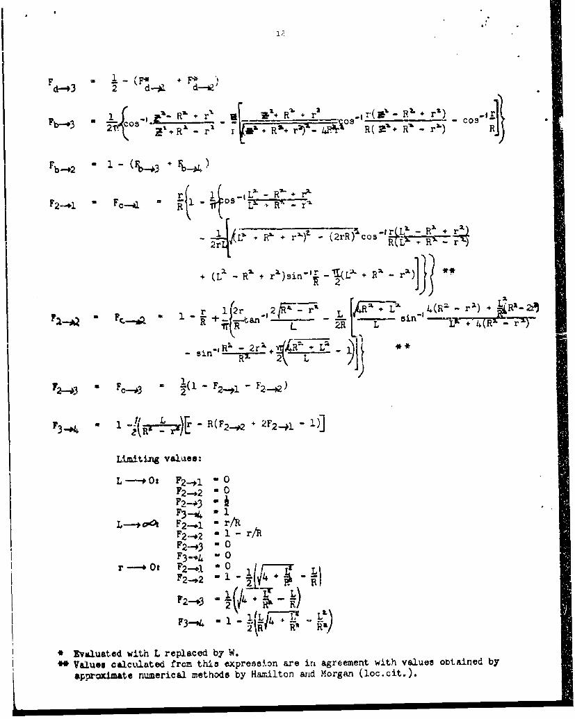
F ~ (F +d-43 2 d-*1. d-
e -+ R'+ + r( ~ Rý r 2Fb-# 140 z ' -r + R*'6+ 4R2 i .. R(etR-P r') R,
Fb-42 0 -("~ 3 +b--44
r 0 9 + -x
jL + R' + r' -~ (2, Co-o L I+.r
-
2M~
F20 Fc.... 3 u O.- F2 -.ý1 -
F3 -0 a - r-RF-# + 2F 2... ý1
Lim-ItIng valuaes:
L-*o0: F2- *l 0
F3 1 -- 1L-eOOk F2 ,.j r/R
F 3 -k 4 0
Fd2-.+ - ;L~j
*Evaluated with L replaced by W.
6*Values calculated trcm thise xpress~.on are in agreement with values otaapinred by
aPproximate numerical methods by Hamrilton arid Morgan (joc.cit.,).

13
OUTER CYLINDER TO ITSELF
OUTER CYLINDER TO INNER CYLfDER
0 - 094
06 06-
00.5 0.50
0.4- -O 4
0.3---0230.(0o.,2- 0o": -Ls-
0 01- 021. 002052809I
0 0.1 0.203 0.405 0.607 0.8 09 10 0 0.1 0.2 0.3 0.4 0.5 0.6 07 08 0.9 1.0
t,/ R t/
VI Concentric oylLndeis of equal length, one inside the cther
,r ---- Ri F2--o -• - - "0
F2-,3 - 0F3--+ 4 0
-r R'oL L + "+ r
or w -o, • . , - 1 " e• ' , L' + • " r;-+ z" " • R L R - *or -*O _ 1 L r + R' r r + R-' 2 r (L + R 2 -rn"%
orM-0: F...pa + +(2rt-an--1ý +777T-+ InR 2R 2RflI + 4iý 1r)(R L R R
2R" 4WR - r") + IL(Rm - r)sin)

14-
VII Cylinder and Plane of Equal Length Parallel to Cylinder Axis, Plane OutsideCylinder.
-•21 curved surface of cylinder
2 planeK > 3 one-half of planea' R radius of cylinder
L height of cylinder and planeS distance from cylinder axis to plane
Ire T length of planea vertical differential strip of 2b differential element of ax distance from a to center of 2y distance from bottom edge of plane to bsiR
Fl- -1 - t+ + b.--I- r
~x +' +RRS%-
L R+ .c 0 5I
SR
F•_• SR 1 os=1 : -S I -- -+ R
S-_ *S+ S + x - A + 4 - - ÷ •
).L>!L + S'+x~R ,e•]+ 4 .1),Rlcs..S.S•> X&+Rs+ei •
L+ S2 +
+ (L1 - S- + R') - ' -R -_ T + %+
F2 _ 1 -
0

Limiting value3:
or y --*L : F ---- j' C. Xs + x
-L [ +? S1 x + R .OS- R (L'-Sx'+x iO-)R L+ N + -X R"'f+ 4L'¶R ~(iL+ s',+ R- L)
-Cos
L *-A Fb RS
T T5
Fa.-,1 0
S -*o: Fh -u1 0
S-R: F0 INIZx cs-
__ 'L + X1 2R- 'Cs(, ~
R-y~l +2)x 4y:IR' R x( 2 + x2)I
+ w
+ 1+2eto'lXL

1w
S-MR: F R + - 4 - os
- �!4 7 ,2)'÷+ 4L o'"Cos-' R (Lt - •
+ R - + *2
L( - x ) sin TOR xa) 2
R -O: Fb. -1 0Fa-.#1 0F2 _-1 - 0
T -0: F2 " 1 '!-*I
* evaluated at x - 0
VIII Cylinder and Plane of Equal Length Parallel to Cylinder Axis. Plane inside Cylinder
I vertical inner burface of cylinder2 side of p2ane facing 13 one half of planeR radius of cylinderL height of cylinder and planeS aistance from cylinder axis to plane
(taken positive as shown)a vertical differential strip of 2x distance from a to center of plane

17
tL L 4 L (30 L5+-- - SS~~i~~
+ XLl , (p2. S2-_ X+ L' ______x
4 S:_, XI + I:, ZL(XI 33 .AýX
+~~~~~ coL-I R¾ +¾ i' 1 - j-i- e2-x.. .
+o-2R)ý 2(tR- S-"- x2-- LýJ + x(Rý+ S2+ xý'* -
(R -~ s -;ý ____S Xý
+ Cos'~ S2 - )a 2R'x' + x(R'- -S+ xcj - s
+ F B]
LimitiLM valuest
x -0: F&..*i 1 -+ -ý (ýL R S-)coS -'- wtL
iftan[-I R/~ + Ua-R- %xv
+ + L
x -i0and S---4R: FL -~--*ao F~i
4- 1

18 1
1X Two Concentric Cylinders of Different Radii. One Atop the Other
1- _rr s--
2 inner curved surface of bottom cylinder
, 3 top of cylinder 14 base of cylinder 2
R radius of 2r radius of 1L, height of 1Lx height of 2a differential vertical element of 2.b differential element of aB height of b fromr base of 1
A. Li -
(2 receives no direct radiation from 3)r1i R] , + + E ]
Ra + III 1"
F -t• 1 , -•r. ..
b F_0 + RrrV(2LO i. i 'e r 2r (+ L)4 (Vr VA2 R~ r1 4L, g r' r -A r a
B- - r)- 2L>r1(
/

. 1) 2
LL jF I + 4F-0 . F a _ W+4-- -
Limiting values:
Z---#o, Pb... "i an'- " I + r A -- (R - - Lo)Le ).r• R + r%-)2" - 4R'ar R(L" + - r")F---
-cos-I
•--. . _ + 2R _L2._and r-R•i Fb4 _--i -_.
r---R+ FI, R L ,*2.L =.- ~ "L\ L., /+ P+ L,+ 2L,_ ,'r+ R l---ý [4 R
SConcentric Cylinders of Uneaual Length. One Enclosed by tha Othm.
1 exterior surface of top inner cylinderS2 exterior surface of middle inne-r cylinder ---7 3 extorior surface of bottom inner cylinder _---
Sinterior surface of top outer cylinjer5 interior surface of middle outer cyllnder.6 interior surface of bottom outer cylinder7 annulus between tops of 1 and 48 annulus between bottoms of 3 and 6S9 ainulus between bottoms of 1 and 41 0 annulus between bottoms of 2 and 5R radius of outer cylindersSr radius of inner cylinders
SL, beight of top cylindersLz height of middle cylinders
L L3 height of bottom cylinders9 and 10 are used for calculation purposesonly and do not shield radiation betweenrcylinders.F2* +I 6-rzl2-FO
+ F8_--#
+ F5 [F--*I + 2 + 3 F-# - ~l-g, LFS_.&o - L! -F7-r: " FlOO _*__ -F- ,-=- R r-
F's on the right side of the above equations may be evaluat-d from VI (two Lehcentriccylinders of equal leng.h).