
AD-A231 730 - apps.dtic.mil · cold region test site characterization, exercise planning, and...
194
AD-A231 730 AN ASSESSMENT -F :MOT'LY IPERATE? IN THE ARCTIC ff UKMN a TIC EIT 1 DT!Ct~~ FE c TE EB ,01991i1 r
Transcript of AD-A231 730 - apps.dtic.mil · cold region test site characterization, exercise planning, and...
AD-A231 730
AN ASSESSMENT -F :MOT'LY IPERATE?
IN THE ARCTIC
ff UKMN a
TICEIT
1 DT!Ct~~
FE c T EEB ,01991i1 r

AN ASSESSMENT OF REMOTELY OPERATED
VEHICLES TO SUPPORT THE AEAS PROGRAMIN THE ARCTIC
Contracz N00014-84-C-Q i80
.~iiScience Appication), Ip'k-naviooro Coq~xyratpon
MTRM10N STXE~r
5Jpm-od for public r.Ilanug
Post O)tlcio Hox 7X() 1/10 Gooit'ikji Drive, Mit oan. Virqginia 22102, (A0U 821 3ik')
SAIC-86,1144
AN1 ASSESSMENT OF REMOTELY OPERATED
V7EHICLES TO SUPPORT THE AEAS PROGRAM
TN THE ARCTIC
Contract N00014-84-C-0180
SAIC Project 1-425-07-545
Precared by
A. B. Rechnitzer
W. W. Denner
E. C. Fstes
Science Applications international Corporation
205 Montecizo Avenue
Monterey, California q3940
TABLE OF CONTENTSPage
ACKNOWLEDGEMENTS.....................iii
EXECUTTVE SUMMARY.....................vii
1. INTRODUCTION....................1-11.1 Data Requirements..................1-21.2 The Arctic Operating Environment. ......... 1-61.3 ROV Technology Overview...............1-191.4 Objective of This- Study...............1-251.5 Definitions.....................1-25
2. ROV TECHNOLOGY HISTORY A~ND TRENDS ......... 2-12.1 Tethered Free-Swimminq Vehicles (ROVs'.......2-22.2 Towed ROV Systems..................2-92.3 Autonomous Underwater Vehicles............2-112.4 Bottom Crawling Vehicles...............2-21
3. ROV SYSTEM COMPONENTS............... 3-1I3.1 Materials and Luhricnts...............3-13.2 ROV Structure...................3-23.3 Remote and On-Board Power.............3-33.4 Small Self Contained Power Sources. ........ 3-63.5 Umbilical Tether Cable...............3-193.6 Acoustic Communication Links ............ 3-213.7 Television.....................3-223.8 Lights.......................3-233.9 Film and Video Camera Recording...........3-243.10 Manioulators/Tools..................3-243.11 ROV Propulsion/Maneuverability/Self Noise .... 3-273.12 Operating Depth Rating and Horizontal Range ... 3-273.13 Speed and Thrust..................3-283.14 Acoustic Subsystems.................3-293.15 Obstacle Avoidance/Search and SurvoV Sonars ... 3-333.16 Buoyancy......................3-373.17 Remote Control Station...............3-373.18 Deck Space.....................3-383.19 Launch/Retrieval..................3-393.2; --ersonne1 & Training................3-433.21 Operator Training..................3-453.22 Guidelines for Selecting ROV Systems for
Arctic Applications...............3-49

TABLE OF CONTENTS (Continued)
Page
4. THE ARCTIC ENVIRONMENT AND ROV OPERATIONS . . . . 4-14.1 Introduction..............................4-1
4.2 ROVs in the Arctic...................4-24.3 Through-Ice Launch/Retrieval Openings........4-5
4.4 ROV Loqistics Support in the Arctic........4-104.5 Launching/Recovery of ROVs and AUVs from
Arctic Pack Ice................ 4-11
5. SUMMARY AND flZ-COMMENDATIONS.............5-1References......................5-4
APPENDIX 1 List of ROV's Including Operating Depthand Dry Weight, January 1986 ......... A-1
APPENDIX 2 Directory of Active ROV Users .........- 2
APPENDIX 3 ROV Manufacturers and Operators........A-3
APPENDIX 4 Recent Pertinent Publications, 1982-1986. .A-4
AoCession For
NTIS -PA&TD-1 1 TA?,
'I ut t onA
i

ACKNOWLEDGEMENTS
Throughout the past 15 years a small cadre of indi-
viduals have dedicated much of their time and talent pulling
together information on remotely operated vehicle technology.
A substantial portion of the study material used to develop
this report has been derived from their information data bases
and personal communications. Specific ac-nowledgement and
recognition is therefore due the two most helpful individuals,
R. Frank Busby and Deam Given. Their assistarce and resources
significantly accelerated the start-up phase of this study.
Many individuals of the informal "ROV Community"
have shown interest in the study objectives and have shared
their time and knowledge to provide specific content to this
report. There was unanimity among them that ROVs have yet to
see their zenith as a useful tool for scientific research and
has had little opportunity to show its full potential for sup-
porting scientific research in the Arctic.
Our thanks are extended to our Canadian colleague,
Jim McFarland, President, International Submarine Engineering,
Ltd. for sharing his first-hand experience operating ROVs and
autonomous underwater vehicles (AUV) in the Arctic. His cor-
respondence has been prompt and embellished with photographs
of ROVs that have operated under the arctic ice. He shared
his future plans for systems that will be dedicated to arctic
operations. Dan Johnson (formerly of AMFPEK-Straza), and
George Clausen, Honeywell-Hydro Products, in addiLion to pro-
viding information and a tour of their manufacturing facili-
ties, offered to help underwrite the cost or publishing the
iii

proceedings of a planned industry, university, U.S. Navy work-
shop on the potential of ROVs to support scientific research
in the Arctic; their offer, and similar offers from others, is
deeply appreciated. The visionary engineer Graham Hawkes and
marine biologist Dr. Sylvia Earle, Deep Ocean Engineering,
Inc. provided their ROV PHANTOM 300 for e-ean testing by the
authors which was especially appreciated. Assessing the
potential of ROV technology through this hands-on experience
was invaluable to this assessment study. Poward Talkington
and Bob Wernli, Naval Ocean Systems Center provided historical
and current information on the Center's continuing development
of the U.S. Navy capability in ROV technology for which we
were most grateful. The MTS ROV Conference and Exhioition,
initiated and organized by Bob Wernli and his Marine Tecinol-
ogy Section team, is internationally recognized as the prcmier
annual event for those concerned with this technoloqy. When
we needed information on personnel and training we turned to a
rrost cooperative leader in diving and underwater vehicle
services, Andre Galerne, President, International Underwater
Contractors. He provided his personal philosophy and germain
information regarding the curriculum for a remotely operated
vehicle pilct/technicial training course that his company
created to meet a world-wide need.
The authors took advantage of the time and talent of
company spokesman present at the exhibit booths at the Off-
shore Technology Conference; the Marine Technology Society,
San Diego Section, ROV Conference; and the Marine Technology
Society and Institute of Electrical and Electronic Engineers!
Ocean Engineering Society. The booth-standers provided an
explanation of their respective products and how they might
iv

be applied in th? nrctic regions. Many of tne firrns visited
are identified in the Appendix "Directory". The Proceedinas
and Conference Records for these annual Pvents over the past 4
years are referenced frequently as they are the priatary in-
formation exchange avenues used by the "ROV Community".
Dr. Elliot Weinberg, Naval Postgraduate School,
Monterey, CA provided an extensive computer read-out of pub-
lished articles for which we are most grateful. Eleanor Estes
performed the yeoman's task of preparing the final version of
this manuscript.
m V I ] m m ]II
EXECUTIVE SUMMARY
The U.S. Navy requirement tc assess the performance
of acoustic systems destined to support naval operations in
the Arctic includes the nzed to collect environmental data for
cold region test site characterization, exercise planning, and
operational analyses. New techniques are being sought in the
interest of cost-effectiveness and improved data collection to
support the spectrum of acoustic systems presently employed
and under development
The Anti-Submarine Warfare Environmental Acoustics
Support (AEAS) program is responsible for the collection of
environmental data adequate for area characterization, exer-
cise planning, and field investigations related to the test
and evaluaLio' of a broad range of passive and active acoustic
sensors. Classical low-latitude environmental data collection
equipment and methods have inherent shortcomings when employed
in the Arctic. Accordingly, the AEAS program has a continuing
need to identify and acquire more cost-effective new technolo-
gy support to field assessments of acoustic systems perform-
ance in cold, high-latitude regions and to add significantly
to its arctic environmental information data base. This study
report is the result of an assessment of the support potential
that remotely operated vehicle technology offers to environ-
mental data collection and the performance evaluation of
acoustic systems under the arctic ice canopy and in the marg-
inal ice zone.
ROV technology research and development has been
underway within the U.S. Navy for more than 3 decades and its
technology base has served as the principal national resource
for the present state-of-the-art systems. It is fortuitous
that remotely operated vehicle technology has proven to be so
V i
cost effective in the commercial offshore oil and gas indus-
try. ROV technology has been applied cominercially in deep
water locations, such as the Gulf of Mexico and the North Sea,
where it has assumed many of the work functions of the human
diver. ROVs have successfully completed a broad range of
tasks, often under conditions that would be considered hazard-
ous to human divers. At present, tethered ROVs are fulfilling
a large proportion of the undersea support requirements for
real-time observation and manipulative functions. Autonomous
underwater vehicles are being investigated by university and
industrial R&D teams for missions requiring greater horizontal
mobility.
ROV technology now offers unique proven caoabilities
for positioning sensors and instruments in three dimensions
for either real-time or delayed data collection. The hori-
zontal and vertical mobility offered by the technology will
permit access to areas oeneath the arctic ice canopy in an
unprecedented way. Several military applications for this
technology exist and additional R&D is underway to create"smart vehicles"; the R&D includes investigations into arti-
ficial intelligence and robotics.
This study included the development of a world
in-entory of remotely operated vehicles (approximately 270
different designs) that included their physical characteris-
tics and principal functions. Many state-of-the-art environ-
mental sensors can easily be integrated into an ROV system to
provide both real-time and self-recording data sets.
vii
The study effort attempts to answer the followin-i
questions:
1. What are the capabilities of current ROV tech-nology to satisfy AEAS environmental supportrequirements?
2. What are the ROY technology shortfalls, if any,that need to be resolved o, further R&D In orderto fulfill AEAS requirements{
3. What are the ROV techr.oogy trends?
4. What is the status of '.S. and Canadiai. ROVexpertise and manufacturing capability?
5. What publihed information is available on ROVtechnology?
6. What actions should be taken by the AEAS programregardLng the applicaticn of ROV technology toAEAS raquirements?
Although this study purposely emphasized the remotely operated
vehicle technology support rotential to the AEAS program and
anti-submarine warfare requiremcnts, it is now recognized that
this technology area could immediately serve other warfare
areas. A similar assessment should b, made when operational
requirements are available for other warfa,-e areas.
v ii
AN ASSESSMENT OF ROV fECHNOLJGY FOR AEAS
1. INTRODUCTION
The , tisubm°.rine Warfare Environmental Acoustics
Support (AEAS) program is responsible for providing environ-
mental acoustics support for antisubmarine warfare system
oerformance analysis. AEAS re-ponsibilities can be divided
into the followirng:
* the development of system test and evaliation
plans,
* site selection of system performance analysi3,
* environmental characterization,
* exercise olanning,
* measurement, and
* performance modeling programs in support of ASW
systems.
%EAS is concerned with the full ranqe of ASW systems
(surveillance and tactical).
AEAS is confronted with a new ASW environment in
the Arctic. None of the existing operational ASW systems has
been designed to function under arctic conditions. New
systems are in the design or prototype stages and there are
many unanswered questions. In addition, the environmental
acoustic data is sparse for much of the Arctic and adjacent
seas.
ROV/AITV te;hnology can be applied in a variety of
ways to support the AEAS program responsibilities. Probably
the most significant contribution can be made in environ-
i-]

mental characterization and site selection. But ROV'AUV
systems may also be able to play an important role in exer-
cise and measurement programs.
1.1 Data Requirements
A variety of environmental data are required to
support the AEAS program. This might be categorized broadly
as data related to sea ice, oceanographic and sea floor con-
ditions. Since sea ice conditions (thickness, concentration,
roughness; movement) are largely forced by the atmosphere in
most regions, the meteorology becomes another important cate-
gory.
Recent studies (Thorndike and Colony, 1982) have
s-own that more tian 70% of the variance in ice movement in
t:e .-entral basin can be attributed to the wind. To further
stabish the imoortance of meteorology to AEAS interests we
note t hat the ambient noise field in the central Arctic is
dominated by sea ice fracturing due to wind stress and/or air
temperature changes (Dyer, 1984). The complex nature of the
iir-sea-ice interaction processes is shown in Figure 1.1.
Table 1.1 presents a comparison of relevant envi-
ronmental acoustics properties in the Arctic with mid-
latitude conditions. It shows that there are numerous system
related problems which are unique to the half-channel sound
velocity distribution and rough sea ice canopy. While sound
paths are very stable in the deep water basins in comparison
to oen ocean conditions, the upward refracted energy is
strongly scattered by the rough ice surface (Buck, 1958 and
Dyer, 1984). Near the ice margin the acoustic variability
increases significantly over the central basin.
1-2

x )
LZ <
I-rU
U)
U))UW <
-J cr -
a.
0w
-J _< IL
LL-J
0J
w <-
-*LJ
> LI
o HEcr30z 'a-
z LLJ
0LJ
0
LIZ L
j ):r _
uZ zWI W o 00
j W
4W 0A0 2
1-3C

C-C
< LI --- J, IeL
U C = L-
*()C C>
~x Z/ _j-n L-, * LO
--. = -J~ =.V -i-
LL-J
C<
c-I
3>
n7-- <. -j
3C < :r LnI Lfl -- Jj
0-- -j Ln jn Ln r_
_z
I L z I L J L
x. LLJZ >C -LL LlJJJ
> zC- - V) a. >
>1-

0L
X0"
-O >
> 0 LO
- E-
C CD
< z >
(U' ~ -U "<<
>>- Z'
<0 <
<~ < 00
z z
jj Ocr x uj
= o _
-LA Z 0-
n -0LO1< :
z -i 1-5
1.2 The Arctic OoeratiL y Environment
Figure 1.2.1 shows the Arctic Ocean and adjacent
seas. The Arctic Ocean covers an area of approximately
14x10 6 km 2 . There are two major deep basins -- the
Eurasian (approximately 4000 m) and the Amerasian (approxi-
mately 3800 m) which are separated by the Lomonozov Ridge
which has a sill depth of approximately 1600 m. About one-
third of the ocean is occupied by the adjacent seas -- East
Siberian, Laptev, Kara, and Barents -- with extensive conti-
nental shelves. The shelf areas play a significant role in
the oceanographic and ice conditions in the Arctic as well as
the performance of acoustic systems. The shelves in general
have a thin sediment cover, and are often underladen by perm-
afrost.
The central Arctic is covered by perennial pack
ice with an average thickness of 3 m. During the winter the
area covered by sea ice increases over the summer coverage as
is shown in Figure 1.2.2.
Sea ice is a highly heterogenesis and complex
engineering material. Grown from sea water it contains a
percentage of the salinity of the freezing fluid. Newly
formed ice may have a salinity of 20%, will be a dark gray
color, and spongey. The ice crystals are hexagonal, and are
formed of thin platelets and sea water is trapped between the
platelets in small brine cells. The brine is highly concen-
trated (150-250%) and is in equilibrium with the ambient
temperature. Any temperature change, therefore, results in a
change in the brine volume, and as a result, a change in the
mechanical, electrical and thermal properties of the
material.
1-6

Id
0 -
FRANr, !
L''ANO
5, -NA'
zANADIAN r
1-7-
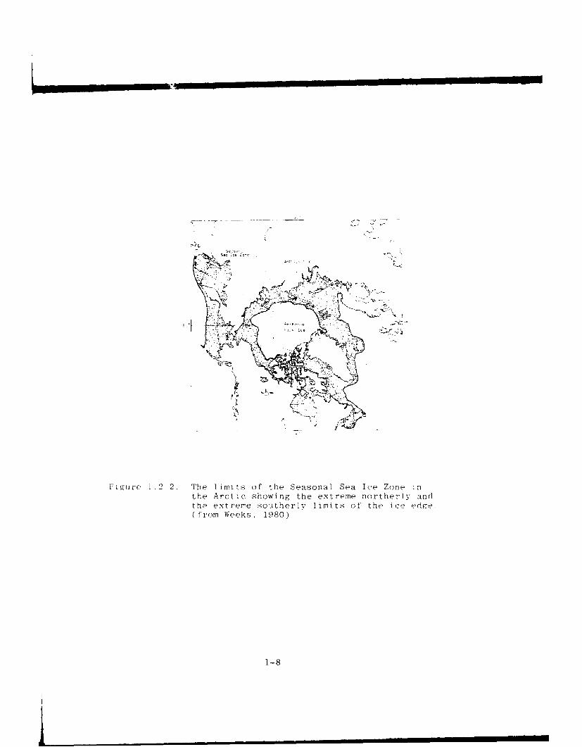
Fig-ure i.2r2. The limits of the Seasonal Sea Ice Zone inthe Arctic showing the extreme northerly andthe extreme southerly limits of the ice edg e.( from Weeks, 1980)I' 18
L~i'-i~t[ I I I I
As the freezing process proceeds the growth is
slowed, less salt is trapped in the ice, the crystals grow
larger, and become more organized. Since they are hexagonal
this means that ice is an anisotrophic material. As sea ice
ages the brine drains from the ice and as it becomes less
salty, it turns from gray, to gray white, to white, to ice
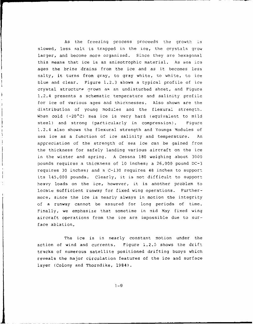
blue and clear. Figure 1.2.3 shows a typical profile of ice
crystal structure crown as an undisturbed sheet, and Figure
1.2.4 presents a schematic temperature and salinity profile
for ice of various ages and thicknesses. Also shown are the
distribution of young modules and the flexural strength.
When cold (-20 0 C) sea ice is very hard (equivalent to mild
steel) and strong (particularly in compression). Figure
1.2.4 also shows the flexural strength and Youngs Modules of
sea ice as a function of ice salinity and temperature. An
appreciation of the strength of sea ice can be gained from
the thickness for safely landing various aircraft on the ice
in the winter and spring. A Cessna 180 weighing about 3000
pounds requires a thickness of 10 inches; a 26,000 pound DC-3
requires 30 inches; and a C-130 requires 48 inches to support
its 145,000 pounds. Clearly, it is not difficult to support
heavy loads on the ice, however, it is another problem to
locate sufficient runway for fixed wing operations. Further-
more, since the ice is nearly always in motion the integrity
of a runway cannot be assured for long periods of time.
Finally, we emphasize that sometime in mid May fixed wing
aircraft operations from the ice are impossible due to sur-
face ablation,
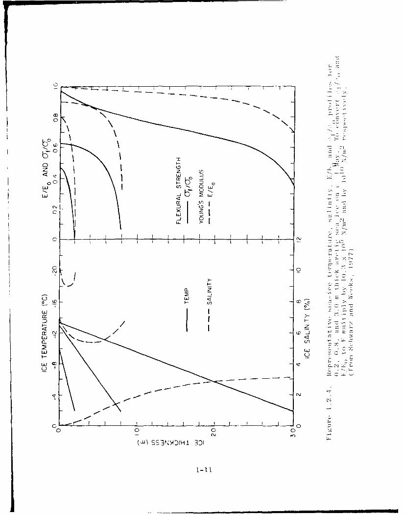
The ice is in nearly constant motion under the
action of wind and currents. Figure 1.2.5 shows the drift
tracks of numerous satellite positioned drifting buoys which
reveals the major circulation features of the ice and surface
layer (Colony and Thorndike, 1984).
1-9

THIN SECTION FABRIC
HC)RIZONTA_ VERTICAL D 1
INFILT ATED crr,
• :::. . .. "SNOA ICE
I . : I __T__T___
S.E QRANSIT ION
V TER
Figure 1.2.3. Schematic; drawing showing several aspects of the
structure of' first-rear ice (from Schwvarz andWeeks, 1977).
The labric diagram shows the degree of order in
the crystal orientation. The outer circle rep-resents the case of horizontal orientation in the
principal axis. The grouping of the points along
the outer circle renresents a preferred horizontalorien tat ion.
1-10
Lo 3 I
I I
z U
000wx
u cc
aK-0uif
u-J if
LUJ Ld
uLJ CZ
0) 0
- -~ f
(W)~ SS3NY)HI 3DI
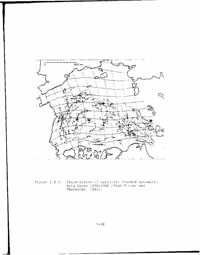
FIi £rr 1 .25. Trajectori os o F Iae i tc t rackod automat icdata buoys 1979-1982 (from C lony andThorndiko , 198.1) .
1-12
Under the stresses in the pack icz the ice breaks
and exposes the ocean. Young ice grows quickly (several
centimeters in 24 hours) during the winter. Figure 1.2.6
shows growth rate as a function of air temperature. As the
forces shift this young ice breaks up to form ridges of ice
which may become tens of meters from the top of the sail to
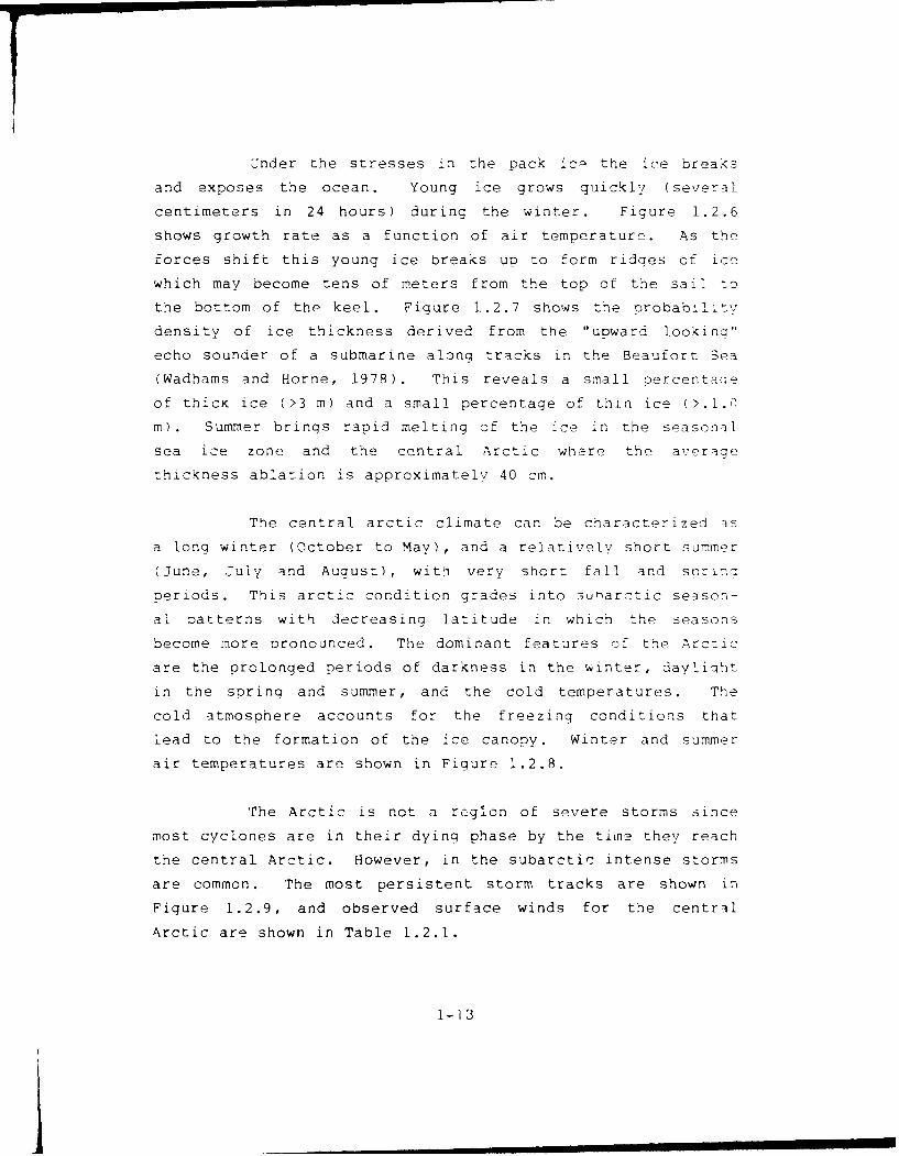
the bottom of the keel. Figure 1.2.7 shows the probability
density of ice thickness derived from the "upward looking"
echo sounder of a submarine along tracks in the Beaufort Sea
(Wadhams and Home, 1978). This reveals a small oercentase
of thicK ice (>3 m) and a small percentage of thin ice (>.i.0
m). Summer brings rapid melting of the ice in the seasonal
sea ice zone and the central Arctic where the average
thickness ablation is approximately 40 cm.
The central arctic climate can be characterized as
a long winter (October to May), and a relatively short summer
(June, July and August), with very short fall and snrino
periods. This arctic condition grades into s3uarctic season-
al patterns with decreasing latitude in which the seasons
become more pronounced. The dominant features off the Arctic
are the prolonged periods of darkness in the winter, dayliqht
in the spring and summer, and the cold temperatures. The
cold atmosphere accounts for the freezing conditions that
lead to the formation of the ice canopy. Winter and summer
air temperatures are shown in Figure 1.2.8.
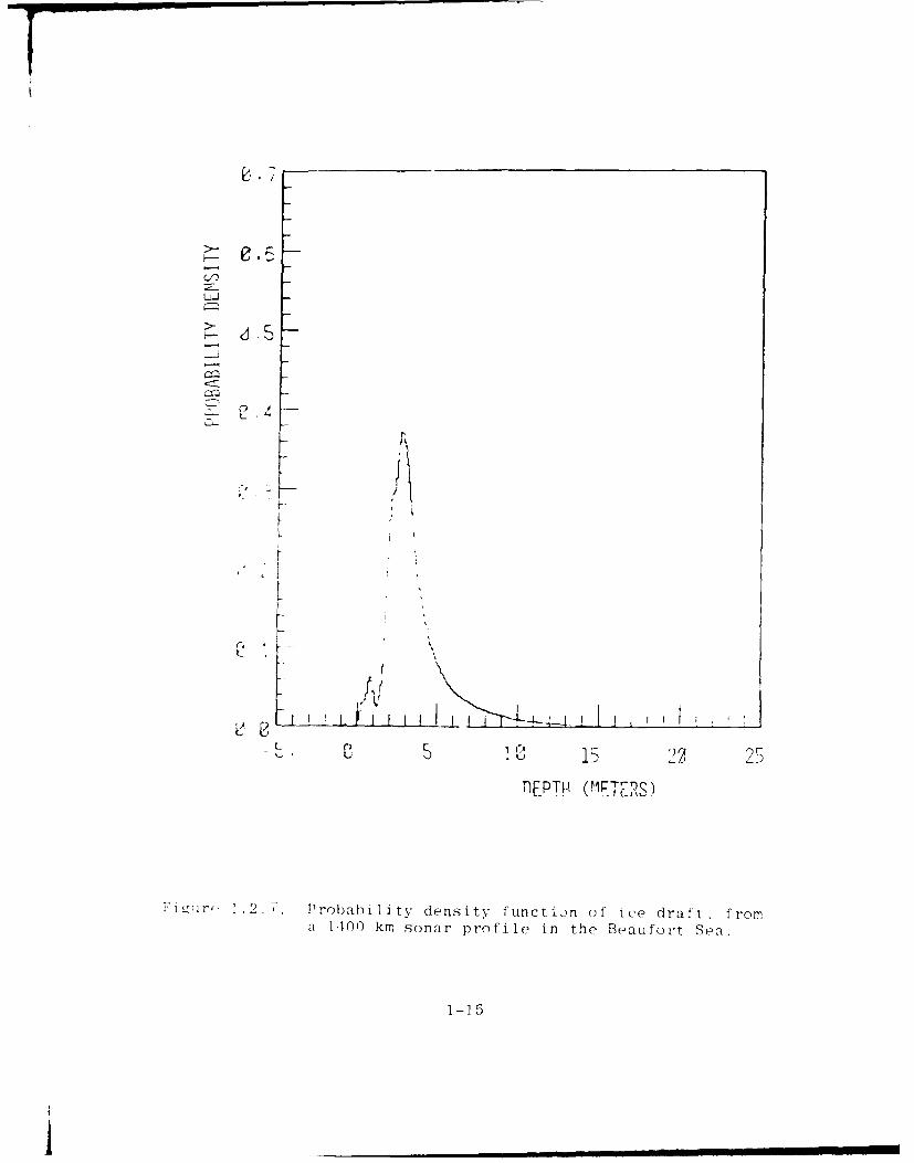
The Arctic is not a regilon of severe storms since
most cyclones are in their dying phase by the time they reach
the central Arctic. However, in the subarctic intense storms
are common. The most persistent storm tracks are shown in
Figure 1.2.9, and observed surface winds for the central
Arctic are shown in Table 1.2.1.
1-13

E 6C-,
0-40
2-2
010 20 4C 60 80 100
ICE THICKNESS (cm)
*., t- . .6 DeopE ,ndz-nce nt' :r )%th rato - in vounl-r seoa ic, ,n i ft hi (kflesS- fripr ai r topir eratur(.s- ()f - 2 - mld-If n f rom Mav yku t I1P8 1
uJ
_J
FL -4,. I
,. 5 15 25,lEPTI- (M TRS)
-i~r, 1 .2.7. Probability density function of' ice draft, froma .100 km sonar profile in the Beaufort Sea.
1-15
ii

(r a
I,-
_c
(L.
op
% %
1-1

0 'IT M L n a r 01) m 0 In Ifl r- r
Z 4- In In In -z - o D In U-) In .o -O0
nj0- 0 -4 (N (Nj (N '-4
z
0 1 LO In (Y) N- co "C N - :
-4 -
* ILz 10 In In Ln N. D' ON M Ln r- i
-4-
zoE--
= (N in) un Ln In Lo c in in (N in) c,
co rn N (N N- k. rn t in -4 P N 11C N-4 -4 N r -4 -4 -4 - 4 - -4 r- -
zCO i
C) 0 ) 00 Inn ICo U) (,j - C~ N
CY- 4 - 1 --4 -4 -4 -4 - 4
-4 r-4 -4
U)
41-1

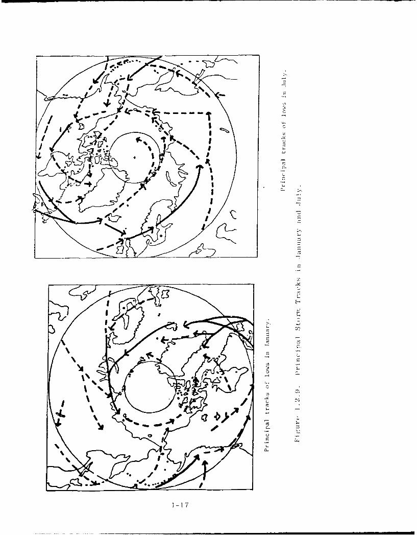
The Arctic is characterized by low precipitation
(mostly in the form of snow) as shown in Figure 1.2.10. but
high incidence of cloud cover particularly as one moves into
the subarctic regions (Figure 1.2.11).
These factors combine to create a challenging oper-
ating environment for men and equipment. Since the early
part of the century the United States and other arctic ;itr
nations have built up a substantial amount it operating
experience. The Soviets not only have the largest arctic
research and development program (by far), but also the
greatest amount of exper4ence in arctic operations (Denner
and Sides, 1985). Tnis effort has been driven by the im-
portance of the Northern Sea Route to their economy, northern
develoor-nt, and strategic concerns.
The three major operating factors in the Arctic are
the temperature, visibility (darkness, cloud cover or blowing
snow) and the sea ice. Taken together these factors pose
some significant operating challenges. From the point of
view of ROV operations in the Arctic the ice is the primary
factor. Temperature and visibility may pose some initial
logistical constraints. However, once a deployment platform
is in place (ship, submarine, ice camp) ROV operations under
the ice should be relatively straightforward. The pack ice
provides an extremely stable platform.
1.3 ROV Technology Overview
This report presents an overview of Remotely Oper-
ated Vehicle (ROV) technology, its proven capabilities,
associated systems and issues for the purpose of assessing
the support potential of this technology for acoustic scien-
1-19
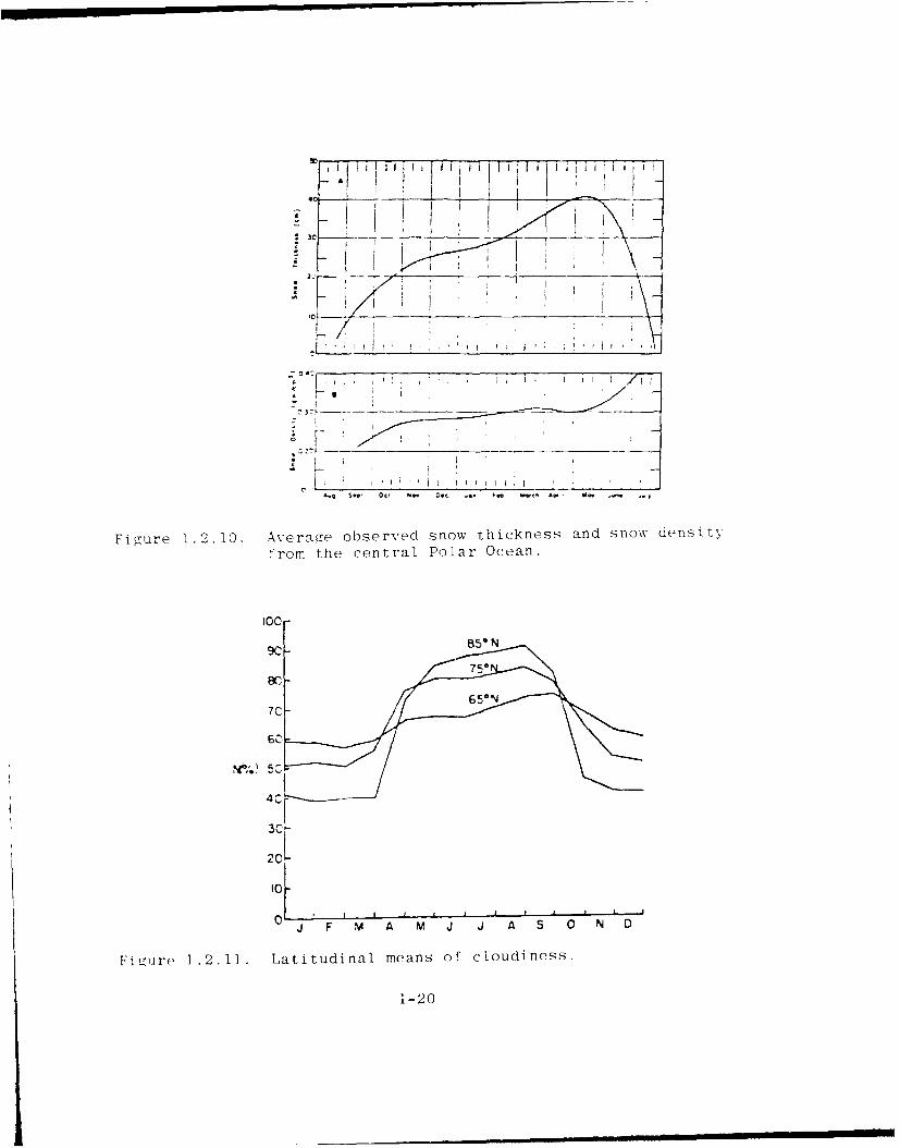
Fi(gure 1.2.10. Averagte observed snow thickness and snow density
from the central Polar Ocean.
100-
41-2
tific research in arctic regions. In the last 10 years this
technology has attained a proven state-of-the-art capability
to perform and carry out functions formerly relegated to the
human diver. ROVs have also become a commercially cost-
effective option for accomplishing a broad range of undewater
tasks involved in each offshore oil and gaz e s
-- exploration, development, and production.
For the purpose of this report we will consider all
types of remotely operated vehicles (autonomous, towed,
tethered, and bottom crawlers) under the broad category of
ROV. Towed systems have been included in this report as
remotely operated vehicles because of the interactive commun-
ication links with the vehicle platform and hybrid systems
that are being developed. A combination towed vehicle with a
tethered free-swimming vehicle carried on-board the towed
vehicle is being developed by the Woods Hole Oceanographic
Institution (WHOI) and is called the ARGO-JASON. In the sum-
mer of 1985 a dramatic feat, the discovery and documentation
of the TITANIC at a depth of 12,500 feet showed the versatil-
ity of the ARGO-JASON system.
The U.S. Navy Supervisor of Salvage and Submarine
Development Group One possesses the principal Navy manned and
unmanned assets for search, recovery, and rescue. This in-
house experience and capability is under continuous up-grade
and represents a valible resource of knowledge. To date,
these organizations have not operated extensively in the
Arctic. The discussion herein emphasizes proven ROV capabil-
ities, potential ROV scientific support applications, and
illustrations of how t-hat technology might be extended from
temperate climates to the Arctic.
1-21
I mmmm m•mmmmmmm
ROV vehicles have accumulated a history of signifi-
cant accomplishments. Since the 1966 nuclear weapon recovery
operations off Palomares, Spain, a number of search and re-
covery tasks have been successfully completed applying stead-
ily improving equipment and procedures. The rescue of the
men in the PISCES III from a depth of 1,500 feet by the U.S.
Navy CURV IiT in 1974 was tollowed by the recovery of the
then high technology F-14 aircraft and its SPARROW missiles
from the North Atlantic. The ROV SCARAB located and retriev-
ed the flight recorders from the crashed Air-India jumbo jet
6,700 feet beneath the Atlantic. Expeditious location and
recovery of the space shuttle CHALLENGER debris involved
several ROVs: DEEP DRONE, GEMINI, CORD, SPRINT 101, RECON IV,
SCORPIO and ORION. These achievements involved a coordinated
effort between manned and unmanned vehicles. The list of
recoveries has grown rapidly.
Despite some spectacular scientific accomplishments
using ROVs in the U.S. only a few researchers have adopted
this technology to their requirements for data acquisition to
support their research. Too, there is only limited effort
dedicated to the design and development of ROVs specifically
for scientific purposes. Nevertheless, germane R&D is under-
way that will provide improved ROV capabilities, some of
which will be applicable to under-ice scientific investiga-
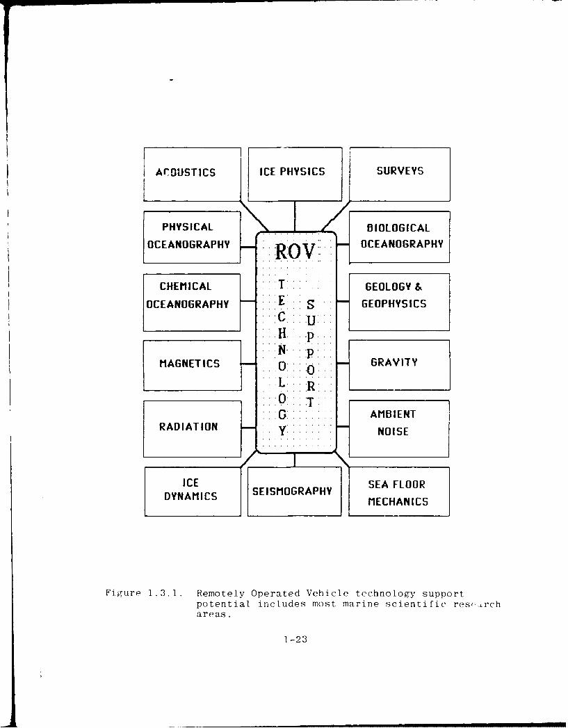
tions. Figure 1.3.1 Remotely Operated Vehicle Technology
Support Potential, includes most marine scientific research
areas. However, ROV technology has neither been extensively
tested nor used in arctic regions.
Recent industrial experience with a variety of ROV
systems shows that the technology can be successfully applied
to a broad spectrum of underwater tasks. It is fortuitous
that industrial needs catalyzed the creation of a familw of
1-22
fACOUSTICS ICE PHYSICS SURVEYS
PHYSICALBIOLOGICALOCEANORAPHYOCEANOGRAPHY
CHEMICALGEOLOGY &
OCEANOGRAPHY E SGEOPHYSICS
MiAGNETICS o GRAVITY
...... AMBIENTRADIATION NOISE
DYAICS SEISMOGRAPHY SEFLODYNAICSMECHANI CS
Figure 1.3.1. Remotely Operated Vehicle technology supportpotential includes most marine scientific res-,rchareas.
1-23
ROVs with capabilities that are diverse and suitable--without
major change--for supporting scientific research activities
in polar regions.
Self-contained scientific sensors and instrumenta-
tion developed for autonomous lon9 endurance oceanographic
buoy installations are readily available from commercial
sources. The spectrum of scientific sensors and instruments
constitutes a ready supply of data acquisition add-ons to an
ROV vehicle. Underwater and atmospheric navigation and posi-
tioning systems have been developed and perfected to meet
virtually every conceivable type of operation.
Reliability is good, but technician support is
required to ensure maximum availability. Surface control
stations have been designed, tested, and refined to provide
"user friendly" operating and to achieve optimum performance
and reliability. Nevertheless, to expedite operator pro-
ficiency development, formal training programs are available
to prepare personnel to operate and provide technical sup-
port. Effort continues to design and develop systems that
will provide full replacement for the now required human ROV
operator. The primary approach to achieving this objective is
through the application of artificial intelligence (a rela-
tively new technology) and robotics.
This report establishes that the technology is at
hand to carry out scientific tasks that until recently could
only have been accomplished by divers or manned vehicles.
These tasks are accomplished for less cost and with no risk
to human life. The ROV has the potential to be every bit as
effective as a corresponding manned vehicle. Indeed, it
could be argued that as a reconnaissance platform the ROV
provides superior data since it can be operated for longer
1-24

continuous periods. The ROV is also cost effective. Acqui-
sition and operating cost per system are less than manned
platforms used for the same purpose.
1.4 Objective of This Study
The objective of this study and report is to:
9 Conduct an assessment of ROV and related technolo-gies that have potential for supporting AEASresearch in arctic regions.
Prepare a document that provides information thatcan be used to acquire appropriate ROV technologyand ROV compatible sensors and instruments to sup-port AEAS research in the Arctic.
1.5 Definitions
The term "remotely operated vehicle" has been used
to describe a wide variety of undersea equipment and system
types. There is no generally accepted definition for the
term "remotely operated vehicle". However, the tethered
free-swimming type is the vehicle type most recognized as an
"ROV". There are ROV system variations that include: towed
vehicles, bottom-crawling vehicles, autonomous vehicles, and
those vehicles that are heavily dependent on contact with the
seafloor or some man-made structure. In general, the term
refers to any class of unmanned vehicle that derives its
guidance from a remote piloting station or from navigation
instructions contained within the vehicle's guidance and con-
trol equipment. This last class of vehicle is more appropri-
ately described as autonomous self-piloted vehicles. ,In this
report the term remotely operated vehicle (ROV) will beused
for tethered free-swimming vehicles and autonomous operated
vehicles (AUV). Clarification will be made when any other
1-25
class of vehicle is mentioned, e.g., towed and bottom
crawling.
For the purposes of this report and to provide some
distinction for the reader the generic term "ROV" applies to
the following four classes of remotely operable vehicles.
(Some authors have sub-divided the classes even further.)
1) Tethered Swimming Vehicles. A remotely operat-
ed vehicle system that is cable powered and controlled via an
umbilical tether cable. Propulsion is integral with a mobile
platform equipped with a variety of sensors and manipulators
to conduct useful underwater work. The vehicles can be
operated in three-dimensions. This type of vehicle is uni-
versally known as an RC'I.
2) Autonomous Underwater Vehicles. An untethered
swimming vehicle system that operates in three-dimensions
free of an umbilical cable. Power, propulsion, maneuvering,
control, and other features are basically under the pre-
programmed control of on-board computer programs. Inter-
active control and data telemetry is via acoustic link. This
type of vehicle is generally recognized and is called AUV
(Autonomous Underwater Vehicle) in this report.
3) Towed Vehicles. A remotely operated vehicle
system propelled and maneuvered, primarily in two-dimensions,
by a surface tow vessel. Vertical maneuvering is achieved by
winch lowering and lifting. Acoustic, magnetic, and optical
sensors acquire information that is displayed at a surface
located console. No generally accepted acronym exists for
this vehicle type.
1-26
4) Bottom-Crawling Vehicles. A remotely operated
vehicle that operates via a tether umbilical cable and in
two-dimensions on the seafloor. The vehicle receives power
and control from a surface support platform. These vehicles
have a substantial payload capacity for sensors, manipu-
lators, tools, and other equipment useful for seafloor mea-
surements, installations (including trenching and burial of
pipe and cables), maintenance and repair. No generally
acceptable acronym exists for this vehicle type.
There are a number of major components common to a
complete ROV system:
1) A remote control station.
2) A remote power source (using either the mainpower supply of the surface ship or an ROVdedicated power plant).
3) An umbilical tether cable. (The autonomousvehicle is an exception.) The umbilical cableusually provides power, a communications link,data telemetry, and serves as the strength mem-ber for launch/retrieval. Communications anddata telemetry to and from an AUV is accomp-lished via an acoustic link.
4) A launch/retrieval system (crane/boom, tractionwinch, storage winch, and in some instances, adeployment cage.
5) An underwater vehicle.
6) Tools, sensors and instruments to conduct spe-cific missions.
This report contains information (Appendix 1) on
more than 268 different types of ROV (the world-wide total
fleet of vehicles numbers somewhere near 700). Appendix 2
provides a directory of suppliers, and Appendix 3 provides a
comprehensive breakdown of specifications. Appendix 4 pro-
vides a list of recent relevant publications.
1-27

2. RuV TECHNOLOGY HISTORY AND TRENDS
The history of modern ROVs spans just over three
decades. The pioneer vehicle in this class was created by
Dimitri Rebikoff in 1953 who converted his normally manned
operated diver transport vehicle PEGASUS into a tethered
cable controlled vehicle. At that time he field demonstrated
the vehicle for both military and academic scientific
researchers but, despite their declared interest in applying
this technology, the marine community did not make a buy.
Little progress in commercial ROV development took olace
until 1975. Industrial demand for an alternative to human
diver services stimulated the market opportunities for both
domestic and foreign sales. Since 1975 the world fleet of
ROVs has grown dramatically. Military applications and pro
curements of ROVs and AUVs will spur the development of addi-
tional units in the coming decade. Already mine neutraliza-
tion vehicles are being developed and produced in substantial
quantities--particularly by France. The majority of no-
military vehicles have been custom designs to meet unioue
functional requirements of offshore oil and gas companies.
Only a few manufacturers have enjoyed multiple sales anc a
production run of a given model.
The introduction of the tethered swimming ROV with
a television camera gave the technic&l personnel, responsible
for offshore drilling and production, their first opportunity
to see what was happening hundreds of feet h iow the surface.
The surface-bound engineer could monitor the operations cor-
tinuously. Communication with the diver while observing the
situation provides a valuable tool for the responsible engi-
neer. The "flying eyeball" is perhaps the key feature of
2-1
ROVs applied in the offshore oil industry. Along with a good
view cf the work site, other innovations have been added to
the ROV, particularly manipulators and tools that they can
operate. There has been a progressive development of ROV
systems -- sensors for expanding the view area, non-destruc-
tive testing devices, documentation systems, and acoustic
navigation and location systems. Many diving operations ar?
now routinely observed and support-d by an ROV. Vehicle
systems can handle all drilling support in deep water and a
great part of it in shallower depths.
Commercial AUV applications have been limited. The
relatively new technology "artificial intelligence and ro-
botics" is being explored for underwater applications, par-
ticularly in AUVs. The level of a tomation research and
development to meet the industrial manufacturing requirements
far exceeds that available for underwater applications. How-
ever, technology transfer from the manufacturing field to
underwater AUV will likely occur. Several experimental AUVs
are under development that incorporate artificial intelli-
gence. These are dubbed "smart fish" to reflect the on-board
environmental assessment and decision-making that will take
ulace in a., on-board compu-er. After analyzing a given situ-
3tion th, AUV will take action on its findings.
2.1 Tethered Free-Swimming Vehicles (ROVs)
During the last decade substantial improvements,
largely driven by thL offshore oil industry, have taken olace
in the design, development and practical application of un-
manned tethered free-swimming vehicles. However, the indus-
2-2
try need to conduct cost-effective exploration, field devel-
opment and, finally, production was satisfied, in part, in
the remotely operated vehicle technology base established by
the Navy.
From 1957 to the present the U.S. Navy has
conducted in-house ROV research and development. The Navy
has also funded university ROV and AUV developments. Most of
the vehicles have been developed as working test beds that
incorporate a broad range of technologies considered
potentially valuable to military operations. The longest
continuous record of RO.'/AUV developments has been at the
Naval Ocean Systems Center (NOSC), San Diego. The Center
draws a significant historical experience base from
developments at the Naval Ordnance Test Station (NOTS),
Pasadena/China Lake, CA. Although NOSC is the current lead
laboratory for ROV/AUV developments much of the early history
credit appropriately belongs to NOTS. The initial Navy
requirement for ROV technology was the need to recover
valuable high technology experimental torpedoes and other new
Navy ordnance that sank during field trials on the test
ranges operated by the NOTS and the Naval Torpedo Station,
Keyport, WA.
The following paragraphs describe some of tie
systems that have been built:
. MERMUTT III. In 1957 the Navy took delivery ofits first torpedo recovery ROV, MERMUTT III, manufactured byVARE Industries, Inc. MERMUTT III was designed to be asearch and recovery vehicle with a depth capability of 1,200feet. The vehicle was 18 feet long, 4 feet 8 inches wide, 3feet 9 inches high, weighed 1,000 pounds in air, had a posi-tive buoyancy of 30 pounds, a submerged speed of 3 knots
2-3
and a hovering capability in a 1 1/2 kt current. It wasequipped with a television. This system became the propertyof NOTS and appears to have been the precutzu. of the pro-gressive in-house upgrades of this design that became CURV(Cable-controlled Underwater Vehicle).
0 SOLARIS. The SOLARIS (Submerged Locatinq andRetrievinq/Identification System) was similar to MERMUTT IIIand was developed for the same purpose to depths of 650 feet.It was an open frame structure fitted with television,lights, an echosounder, and either a toggle-action claw torecover torpedoes, a general purpose claw, a cable claw (forcable repairs), or an explosive magazine, and a stud gun.The vehicle was designed and fabricated for the Naval TorpedoStation, Keyport, by the Vitro Laboratories. Although thevehicle successfully located and retrieved a dummy targetfrom 650 feet it did not pass the established performancespecifications test.
0 SORD. The SORD (Submerged Object RecoveryDevice) was built by the Naval Undersea Warfare EngineeringStation, Keyport, in 1965 for weapon systems recovery fromits underwater test ranges. The system has an open metalframe that supports a television camera, flood lights, direc-tional hydrophone, magnetometer, a mechanical latching devicefor ordnance or object retrieval, and a washout pump that canremove six meters of sediment overburden to expose the objectto be recovered.
* SPURV. The SPURV (Self-Propelled ResearchVehicle), an AUV, was desiqned and developed by the AppliedPhysics Laboratory, University of Washington. It underwentits initial testing in the Dabob Bay, 3-d acoustic test rangeon 25 November 1959. It was designed to cruise under its ownpower to depths of 10,000 feet, at a speed of 6 knots, for 5to 10 hours depending on the type of battery used. Its pri-mary payload was oceanographic instrumentation--100 to 200pounds. The function of the research vehicle was to obtaininformation on ocean bottom topography, and to record oceano-graphic and geophysical data at great depths and over longdistances. Its development was sponsored by the Office ofNaval Research.
* TORTUGA. In the sixties several experimentaltestbed ROVs were conceived at NOSC and fabricated by a com-mercial firm (Hydro Products, San Diego). Among the first
2-4
was TORTUGA. It was purposely sized small to improve testimproved maneuverability ideas and to allow close observa-tional access to spaces inaccessible by the larger designs.Several versions of TORTUGA were fabricated and evaluated.An carly AeiQ- n ,1'nq water jet propulsion Lost out to moreeffective propellers.
0 ANTHRO. The ANTHRO took its name from itsanthropomorphic features and was build by Hydro Products fol-lowinq NOSC specifications. It was developed to evaluate aconcept wherein the vehicle would mimic the motions of ahuman head attempting to scan and interpret an unfamiliarscene. The technique was termed "head coupled" televisionand involved slaving the vehicle (with its included televioncamera) to the operator's head that was covered by a mastercontrol helmet. Binaural audio inputs were included todetermine if such augmentation would improve the operator'sability to locate and identify a target. In addition, theoperator's control station chair was instrumented to matchthe roll, pitch, and azimuth chanqes in synchrony with thevehicle. Vehicle depth was controlled by servo-controlledvertical thrusters that automatically maintained a desireddepth.
* SCAT. The SCAT (Submersible Cable-ActuatedTeleoperator), as oriqinally configured, was built to serveas a testbed for evaluating head-coupled television. It wassubsequently .odified to serve as a light-duty inspection/work vehicle capable of operating to a depth of 3,000 feet.
0 SNOOPY. SNOOPY is the smallest in a series otNOSC developed light-weight, portable ROVs. It carries atelevision camera with a 250 watt mercury vapor light source.Its primary function is optical viewing to a depth of 100feet.
* NAVFAC SNOOPY. The NAVFAC SNOOPY (NavyFacilities Command SNOOPY) is a small ROV designed for oceanconstruction support. Its primary uses are optical survey ofproposed seafloor construction or implantment sites, monitor-ing and documentation of diver operations, and general under-sea inspection and documentation.
0 LARP. The LARP (Launch and Reco-7ery Platform),another NOSC design, is a unique ROV that is normally operat-ed by scuba divers to a depth of 130 feet. From 130 feet to200 feet the system is cable controlled from the surface.
2-5

Its function is for the sub-surface launch and recovery ofmanned submersibles.
e STSS. The STSS (Surface Towed Search System) isa towed ROV designed for search depths to 20,000 feet.Employing television and side looking sonar, its u.aLput isread and interpreted at a surface located console. It wasfabricated by the Westinghouse Corporation and is operated bySubmarine Development Group One, San Diego.
o CURV. The CURV (Cable-controlled Underwater Re-covery Vehicle) has undergone an almost uninterrupted seriesof upgrades from CURV I to CURV III. Each design has beenthe traditional rectangular open frame equipped with syn-tactic foam buoyancy and ample space for a number of sensorsand instruments. The sensors included are active/passivesonars, television cameras and supporting lights, stillcamera(s) with strobe light(s) and manipulators. CURV III iscapable of working to 7,000 feet and has been modified foremergencies for operation to 10,000 feet. It has a submergedspeed of 4 knots. Two horizontal propulsion motors are usedto steer the vehicle and one vertical motor serves for closevertical control.
* RUWS. The RUWS (Remote Unmanned Work System)was developed by NOSC as a testbed for a variety of usefulwork missions such as recovery, repair, implantment, survey,documentation, and oceanogaraphic data gathering. Work isperformed by a two-arm manipulator system -- one a relativelysimple four-function, rate controlled grabber, and the othera seven-function position-controlled, highly articulatedmanipulator for which special tools were developed.
* MNS. The MNS (Mine Neutralization System) wasdeveloped and tested by NOSC. It is a tethered swimming ROVdesigned to be deployed from a fleet minesweeper. Its func-tion is to classify and neutralize mines that have beenlocated by other means. The system contains its own highresolution scanning sonar and television viewing system forrelocation and classification of mine and mine-like targets.NOSC is NAVSEA's Technical Agent for the commtercial produc-tion run which started in 1985. NOSC is also developing thefirst unit of a new low magnetic signature version of theMNS.
2-6
The commercial application of remotely operated
vehicles (ROVs) has expanded rapidly since 1975. The world
fleet has grown to over ICC in the last decade. Their utili-
ty and reliability has made them almost an obligatory support
service system on each major offshore platform. The offshore
oil industry, in most instances, has nurtured the commercial
development of ROVs with the intent of eliminating or marked-
ly reducing the requirement for the human diver. Ironicily
it is the dexterity and capabilities of man that have been
used as a performance target for ROV designers and develop-
ers. Many tasks and functions formerly assigned to the human
diver are now accomplished by the ROY. These include inspec-
tion of subsea systems, search and recovery. ROV technology
has not been extensively used or even tested in arctic re-
gions. In 1983 the ROV MiniROVER was used to explore and
photograph the remains of the 140 year old British bark, the
Breadalbane, under the arctic ice. The oil industry has used
a small ROV to inspect the ice keels of multi-year pressure
ridges.
A combination of a towed vehicle with a tethered
free-swimming vehicle carried on-board the towed vehicle is
being developed by the Woods Hole Oceanographic Institution.
In the summer of 1985 a dramatic feat showed the versatility
of the towed ARGO system as a means to achieve fine-grain
surveys of the deep sea floor, but also tc locate sunken
ships, as it did when it found the TITANIC at 13,000 feet.
2-7

The towed ARGO will carry a small, remotely operat-
ed vehicle (JASON) in a "garage" located at the stern of the
towed body. Operating as deep as 20,000 feet, JASON will
transmit data on its tether to ARGO which in turn will relay
information via the umbilical cable to the surface shin.
Since the system can remain submerged for weP~s at a time, it
is expected to significantly increase the amount of informa-
tion collected during research cruises. The prototype JASON
is a Benthos RPV-430 with a Deep Ocean Engineering manipu-
lator arm.
In July 1986 Woods Hole personnel returned to the
TITANIC and were able to probe some of the interior of the
ship using the video robot JASON JR, operated from ALVIN.
The cable controlled free-swimming vehicle has
evolved co be the dominanL ROV vehicle class and is the most
recognized ROV type. The ROV SCARAB, for example, located
and retrieved the flight recorders from the crashed Air-India
jumbo jet 6,700 feet beneath the Atlantic. In addition, it
recovered a substantial portion of the aircraft bit by bit.
Such achievements have significance to the scientific
community when one realizes that this operation required
accurate geodetic position fixes for each piece of debris.
Navigational fixes are now accomplished as routinely as
surface navigation.
2-8
.I l N I I I I

In March 1986 the space shuttle CHALLENGER was
destroyed by a rocket booster explosion. The debris field
was extensive and recovery operations continued into May.
Recovery operations inlcuded the use of ROVs SPRINT 101,
RECON IV, DEEP DRONE, GEMINI, CORD, SCORPIO and ORION.
2.2 Towed ROV Systems
Many of the sensors and research capabilities in-
corporated into the design of towed vehicles have potential
application aboard tethered free-swimming and autonomous
underwater vehicles. In addition, some hybrid systems are
being developed that involve both a towed vehicle with a
tethered free-swimming vehicle carried on-board the towed
fish. Hence, the following vehicle descriptions are included
in this assessment.
A representative towed ROV is the SEA MARC CL which
is one of the newest towed sea floor mapping systems on the
market. Incorporated in the towed fish is a 150 kHz side
looking sonar system with a very wide operational envelope.
The system can image swaths from 50 m to 1 km wide and create
real-time, digitally processed, slant range and speed cor-
rected acoustic images of the bottom. The system maintains a
good grey scale across the image over the entire range of
swaths, tow speeds, and towfish attitudes. The quality of an
acoustic image of the seafloor is critically dependent upon
platform stability. SEA MARC CL uses a passively stabilized
sensor platform with optimized towing speeds from one to six
knots.
2-9
Its light weight and small size makes it readily
portable and easy to deploy from ships of opportunity. A
light weight winch and a one centimeter contrahelically
armored coastal cable is required for survey towing. The
system has a depth capability greater than 1500 m. Its over-
all weight is 100 kg, and it is 2 m long, 0.4 m wide and 0.4
m hiqh.
Unprocessed acoustic data and corrected data can be
recorded in real time on standard audio tape for backup and
post processing. All telemetry communications between the
tow fish and the surface console can also be recorded on
audio tape. All data from sensors such as compass, magnetom-
eter, temperature sensor, and pressure/depth gauge are
digitized for communications to the surface or on-board data
storage. As a towed system the SEA MARC CL uses a hiqhly
flexible multiplex telemetry link to the surface. This link
has sufficient unused capacity to accommodate additional
sensors or systems aboard the towed fish. SEA MARC can also
support a very high accuracy super short baseline tow fish
positioning system to increase survey scope by avoiding the
use of bottom mounted acoustic references.
Operating these towed systems is inherently diffi-
cult because the lonq length of cable involved constrains
maneuverability. Towed vehicles are also constrained by high
winds and sea conditions. These constraints might be par-
tially overcome by using autonomous vehicles.
2-10

2.3 Autonomous Underwater Vehicles
Autonomous ROVs have been used by the Navy since
the early 1960s but their numbers were small. More recently,
due in large part to the advent of the microprocessor, R&D
investment in this type vehicle has seen a greater emphasis
by the military. Since the autonomous vehicle is, by nature,
designed to operate at distances beyond visible range of itssupport craft or station, it can conduct a mission covertly
and free of a surface tether. The capability is particularly
pertinent to this study.
Some 23 development programs in this area can be
identified from the open press. Of these, 14 are supported
by the military. At present most autonomous vehicles are
primarily developmental. The R&D vehicles are being develop-
ed primarily for identifying problems and technology that
must be advanced to make this type of vehicle practical and
an effective alternative to cable-connected vehicles. Al-
though the world inventory of AUVs is less than 30 the number
of vehicles in this class is expected to increase in the next
decade. The operational characteristics inherent to autono-
mous vehicles suggest that this class will have a number of
under-ice applications.
Two general AUV classes are currently under devel-
opment. One is of an open frame design, much like tethered
free-swimming ROVs, and the other is torpedo-shaped which
offers lower drag for long-range traverses.
Tne developmental program of Gaseby Dynamics of the
U.K. illustrates a few of the potential applications for this
technology. That firm is currently developing an intelligent
decoy and has prototype systems under test. Mounted in maga-
2-11
zines on a surface vessel, as many as six of these vehicles
can be deployed into the water if the presence of acoustic
torpedoes is suspected. Against a passive seeker it would
automatically begin a seduction or distraction program, while
against an active seeker it would store the sonic transmis-
sion then retransmit it with added dopler and time difference
to attract the torpedo. (Military Technology, Vol. IX, No.
11, 1985). Such decoys could also be launched from sub-
marines or aircraft.
The European-based Scicon Company's SPUR (Scicon's
Patrolling Underwater Robot) is an advanced concept in the
design phase (Busby, 1986). The full-scale vehicle would be
between 10 and 11 meters long with a 1.8 meter cross-section.
Normal propulsion would be by an oxygen/hydrogen fuel cell
and higher attack speeds of up to 50 knots may be obtained
from either a closed-cycle engine or batteries. At cruising
speed the vehicle would have an action radius of 1850 kilom-
eters, an endurance of two months and, for certain applica-
tions, be capable of diving to 6000 meters. SPUR would be
under shore control and artificial intelligence would be used
to assist functions which SPUR would need to perform autono-
mously, especially in the fields of tactical decision-making
(e.g., route planning, target classification, attack maneu-
vers, and communications routines). Scicon foresees such
roles as mine counter-measures (using manipulators), vessel
destruction via torpedoes, wrap-around wire system deployment
directed against a ship's- propellors, and, as a last resort,
an intelligent mobile mine. The company further envisions
"wolf packs" of SPURs deployed in a patrol line to create
barriers up to 370 kilometers long.
2-12
The French built (IFREMER) AUV EPAULARD is a survey
vehicle designed for photographic sorties in deep water (6000
M). It can take 5,000 photographs in one dive and has been
found to be highly effective in the following field investi-
gations:
* surveys of manganese nodules in the Pacific,
* sediment slumping observations in a canyon offthe coast of Nice, France.
* search for saliage and cables, and
* trials on the Gorda Ridge, off the coast ofOregon.
150 dives have been completed. The EPAULARD maintains con-
stant altitude off the seafloor through the use of a weighted
drag rope, combined with a forward-looking obstacle avoidance
sonar which is used automatically to interrupt propulsion in
the event of any collision situation.
An acoustic image-transmission link to the surface
is being developed to operate at 25 kHz and thus transmit a
picture at intervals of 5-40 seconds. The acoustic imaging
capability is intended to improve mission control and search
strategy, not to replace the on-board still cameras. The
vehicle can cover 15 km during a dive of 6 hours. Service
time on deck is 1 hour to recharge batteries and re-load
cameras.
Also under development by IFREMER is a smaller
vehicle system ELIT designed for shallower water inspection
tasks associated with the offshore oil and gas industry. It
2-13

will be much more intelligent than the EPAULARD with the cap-
ability of maintaining station near the ocean bottom and
transmitting video data, through an acoustic telemetry link,
to an operator. System tests are planned for 1986.
The AUN PLA II is an experimental vehicle designed
to carry out research into the feasibility of collecting
manganese nodules from a depth of 6000 m. The development
effort is supported by the French atomic energy research
authorities. The broad principle of the system is that the
vehicle descends under its own weight, with buoyancy and trim
control, so that a soft landing is made on the bottom. The
vehicle then covers a distance of about 600 m on the sea bed,
uses a dredging device to lift nodules into the hopper which
can hold 3 cubic meters of nodules. Ballast is then dropped
so that the vehicle ascends using fixed buoyancy, and is re-
covered on the surface. After processing of the nodules on
board the support factory ship, the waste rock is loaded into
submersible vehicles to act as ballast in subsequent trips.
Additional ballast, for fine trim, would be in the form of
iron shot.
Technomare of Italy is developing an AUV work sys-
tem with remote operator control via an acoustic communica-
tions link and with multiple arms. Some arms are used for
vehicle position keeping and torque reaction, while the other
arms serve as manipulator operating tools. Video information
will also be provided via an acoustic telemetry link to pro-
vide the operator with on-scene information.
At the Heriot-Watt University of Edinburgh,
Scotland, development is underway on a small AUV (ROVER) that
2-14

will transmit video data via an acoustic telemetry link to a
tethered free-swimming ROV operating near the AUV work area
for relay to the surface control station. This approach to
gaining a short acoust'c transmsision path hopefully will
reduce some of the problems that plague long distance acous-
tic transmission of video data.
The U.S. Department of the Interior, Minerals
Management Service, is sponsoring robotics (AUV) engineeering
R&D in an attempt to provide more effective means to conduc-
tion inspection of seafloor pipelines and the inspection of
underwater structures. This AUV technology development pro-
gram, called the Experimental Autonomous Vehicle (EAVE) Pro-
gram, has progressed to a point where both the NOSC and the
Universi-y of New Hampshire (UNH) experimental vehicles
have been tested in water to perform certain fundamental
maneuvers. The vehicles are known as EAVE-WEST (NOSC) and
EAVE-EAST (UNH). Neither of these vehicles is planned to be
a prototype for a specific function, but, as indicated, both
are test beds for new technology and techniques. This tech-
nology development program is a collaborative effort between
the Naval Ocean Systems Center (NOSC) and the University of
New Hampshire (UNH). Germane to this stidy, EAVE-EAST
includes a computer routine entitled "The Arctic Inspection
Mission System Sonar Acquisition Routine".
At NOSC, an open-frame torpedo-like submersible
(EAVE-WEST) has been constructed to study magnetic navication
and optical fiber communications. This vehicle is powered by
lead-acid batteries, which, together with electronics, are
located in the four canisters within the vertical frame.
Twin propellers located aft, and a vertical propeller amid-
2-15
ships, between syntactic foam buoyancy blocks, provide pro-
pulsion for the vehicle.
The AUSS (Advanced Unmanned Search System) is a
current NOSC AUV development. The objective of the develop-
ment is to create an autonomous system for search using
acoustic command, control, and telemetry links in addition to
a significant amount of artificial intelligence te:hnology.
AUS:% will serve as a testbed for overall evaluation of the
system and its subsystems. A secondary objective is to have
a derivative of the AUSS replace the Surface Towed Search
System (STSS). The UFSS (Unmanned Free-Swimming Submersible)
was designed and built at the Naval Research Laboratory in
order to demonstrate and evaluate advanced technolngies as
applied to underwater vehicles.
International Submarine E-ngineering, Ltd., Canada,
built the torDedo-shaped ARCS to perform surveys under the
arctic ice canooy. It is now operated by ifs owner the
Bedford Oceanographic Institute, Halifax, Nova Scotia. 4RCS
has seen limited use in the Arctic and is being prepared for
additional trials in 1986.
The Applied Physics Laboratoiy, University of
Washington, pioneered in the development of AtV technology.
The Unmanned Arctic Research System (UARS) was designed with
under-ice operations in mind and was tested successfully in
the Arctic in 1972. As part of a DARPA-ONR soonsored arctic
technology program at the University of Washington, the AUV
was developed and successfully deployed. The UARS is a com-
pact, torpedo shaped vehicle that weighs 410 kg in air and
has a length of approximately 3 meters and a diameter of 75
2-16
cm. It can operate to depths of 457 meters and can cruise for
10 hours at 3.7 knots. Its payload of acoustic instrumenta-
tion provides for measuring physical phenomena and communica-
tions both to and from the AUV. The vehicle is launched in a
horizontal attitude after being lowered through a 4x12 ft ice
hole. The position of the UARS is known at all times from
information derived from an acoustic tracking system. The
UARS is recovered by ensnaring it in a net. The capture net
contains an acoustic beacon which the UARS homing system
3eeks. In the event that command ccmmunicati-n with the UARS
is lost for a preset period of time, the homing system will
automatically activate and UARS will began a search for the
beacon. The field tests were conducted from Fletcher's Ice
Island (T-3) when iu was at approximately 850 N Lat. and 85"W
Long, about 150 miles north of Ellesmere Island during May
1972. Pressure ridge keels to a depth of 23 m were observed.
Included in the instrumentation suite of UARS was an ice pro-
filer system which measures the relief of the under-ice sur-
face on each of three separate, narrow, upward looking beams,
to provide an overall elevation accuracy of 9 cm.
As a part of the development of UARS, a 10,000 baud
underwater acoustic link was designed and developed. This
phase-shift-keyed (PSK) data link was used both to control
the UAF. and to receive real time data from the vehicle.
Observations of the under-ice profile were made
using the (UARS) system which was develope& as part of an
ARPA-sponsored arctic technology program. Briefly, the
s -e- consists of an acoustic telemetry-controlled, torpedo-
like vehicle that can operate under the arctic ice while
carrying acoustic and other research instrumentation (Figure
2-17
2.1). An acoustic tracking system determines the position of
a tracking projector mounted on the UARS at 2-second inter-
vals. Within a typical 4-km diameter operating area, the
standard error of the position measurement is about 15 cm
relative to an established reference baseline. The vehicle
dynamic controls play an important role in the measurement
process. The vehicle controls its depth within 7 cm, and
Ditch and roll are controlled within 0.50 with 30-sec periods
for all three functions. During turns, slightly larger
errors are incurred, but these damp out very rapidly when
straight running is resumed.
The multi-beam, upward-looking acoustic lens that
is used to measure the under-ice profile is mounted directly
over the tracking transducer (Figure 2.1).
The UARS has been inactive for several years. Dr.
John Harlett, University of Washington, Applied Physics
Laboratory (personal communication) indicates that the UARS
could be placed back in operation by four men with six months
of effort.
Current AUV development effort at the University of
Washington Applied Physics Laboratory is the modification of
an Mk 38 vehicle to do acoustic assessment of krill under the
antarctic ice shelf and pack. The AUV will ne pre-programmed
and will return to the launch platform using acoustic homing;
a technique utilized by the UARS. In this application, there
are no plans to track the vehicle. This is a relatively low-
cost vehicle and is a modified version of the Mk 38 Mod 5
Flect Sonar Training Target which is 204 cm long, 14 cm in
diameter, weighs 7.3 kg in air, has a speed of 3.5 knots for
2-18

- -p
- ~
= ---
o - - --- 4 '-
~ oo --S
____c2~ -~
~ ir ~ L
-t
S3 'S
~ -- *- I.~
- S~ __ 5-: w ~*1~ ~ -
V -~ -S. I 4
3 -~
f
I. 0 p3
*
j ;~ -
5~w
*~i !~
3V *--' -~
gV.-
S
2 9
4 hours, and a depth rating of 152 meters. The current con-
tract calls for a unit cost of $1500.
A capability vital to the ultimate success of un-
tethered vehicles is the ability to acoustically transmit
reliable images in real time. Hence, it is deemed necessary
to develop technologies that support reliable image transmis-
sion. Imaging in near real-time from an untethered vehicle
is possible because of certain data reduction techniques that
can be used. Even at the very low resolution of 100xl00
pixels, digitized to four bits, there is still a significant
amount of redundant information present. Using a special
redundancy removal algorithm (Micro Adaptive Picture Sequenc-
ing) much of the excess data can be removed while important
scene features are maintained.
An image of 100x100 pixels (40,000 bits) would
require about 4 seconds to transmit an acoustic telemetry
link (9600 bps). By using data reduction techniques, it is
possible to transmit the same scene in 0.5 seconds. In or,.,r
to test the usefulness of the data reduction algorithm, an
EAVE compatible imaging test bench was built. On this system
images were sensed, digitized, compressed and transmitted and
reconstructed for a remote ooerator with acceptable image
fidelity and image Lransmission time. If many frames per
second are necessary to control the vehicle through a diffi-
cult maneuver, the compression ratio can he increased and the
transmission time decreased.
There are some drawbacks attendant with autonomy.
All power for the entire mission must be carried on-board.
2-20

This limits the amount of work that can be accomplished --
power must be shared on each mission between propulsion and
the tools/sensors used to carry out a meaningful mission.
Many untethered missions will involve only inspection and
information gathering with no requirements for high energy
for sensors or tools. Real-time viewing at a manned control
center is limited due to the transmission capabilities of an
acoustic communication link. However, without direct human
intervention, the system must incorporate substantial
intelligence onboard which involves extensive computational
capability. Accordingly, the following areas are being
emphasized in AUV technology R&D:
o improvement of sensors and expanding sensoroptions.
0 improvement of guidance systems and artificialintelligence.
0 use of enhanced acoustic communication usingadvanced bandwidth compression.
2.4 Bottom Crawling Vehicles
ROVs in this category are limited in number and
each has been developed for a specific mission. Most of
these systems are designed to conduct pipeline or cable lay-
ing missions. However, the University of California, Scripps
Institution of Oceanography, Marine Physical Laboratory bot-
tom crawling vehicle, RUM III, the latest in the RUM develop-
ment series, is designed to perform research in the deep
ocean and on the seafloor.
2-21
3. ROV SYSTEM COMPONENTS
3.1 Materials and Lubricants
Materials and lubricants used in ROV systems must
be selected and designed to operate effectively under arctic
conditions. Several factors must be considered:
(l) the mechanical properties of the materials
used at cold temperatures,
(2) seals and water tight integrity,
(3) lubricant viscosity,
(4) ice formation on the tether, and
(5) the impact of large and sudden temperature
changes.
Many arctic researchers have learned the "hard way" that
special preparations and precautions are necessary when oper-
ating systems under arctic conditions. Low temperatures
change the strength, elasticity, and hardness of metals and
generally reduce their impact resistance. Leather, fabrics,
and rubber lose their pliability and tensile strength. Rub-
ber, during extreme cold, becomes stiff and flexing may cause
it to break. Rubber, rubber compound seals, and O-rings can
warp. Plastic, ceramics, and other synthetic materials are
less ductile. Items composed of moving parts and of dif-
ferent materials can experience changes in tolerances thus
operate with reduced efficiency. Glass may crack if it is
exposed to sudden change in temperature.
3-1

Lubricants destined for use in ROV systems that are
not specifically developed for cold weather use may congeal
and retard the motion of moving parts if exposed to freezing
arctic air temperatures. Low temperature lubricants (oils
and greases) developed expressly for the winterizing of
equipment may be suitable, but should be evaluated before
going into the Arctic. Lubricants must have a low rate of
viscosity change, a freedom from corrosive actions, and low
volubility. Cold weather lubricants must be capable of dif-
fusion over all surfaces requiring lubrication, and permea-
tion of the pores and surface cracks of metal. Cold weather
lubricants will evaporate at a more rapid rate than do regu-
lar lubricants at low temperatures. Their tendency to dry
out requires frequent checking of lubricated surfaces and
repeated replenishment. Oils, at cold temperatures, become
more viscous and difficult to pump to places where lubrica-
tion is needed. Higher viscosity oils, until they become
hot, increase the drag on engines and moving parts. Grease,
which is a semisolid, also becomes more viscous and loses
some of its lubrication properties. Lubricants are difficult
to apply at cold temperature, fittings may be frozen and
brittle, so that lubrication should be done in heated
spaces.
3.2 ROV Structure
The fundamental structure for larger versions of
tethered swimming and towed ROVs is an open rectangular
frame. The framework serves the function of enclosing, sup-
porting, and protecting the vehicle components (thrusters,
junction boxes, television, lights, etc.). The frame size in
most designs represents the outside dimensions of the ROV.
3-2

Small ROVs and AUVs are usually fully covered with a shroud
over selected portions to improve hydrodynamic performance.
Hydrodynamic considerations are more important to a small
tethered swimming ROV than desired flexibility of access to
the subsystems in larger systems. Vehicle size varies widely
and ranges from the size of a beach ball, e.g., Hydro
Products RCV-225 (0.17 cu. m.) to the automobile size of ERIC
II (27 cu. m.).
Manipulators and mechanical "grippers" (for sta-
bilizing the ROV during work functions) may extend well
beyond the protective framework. In some instances grippers
and manipulators are folded so as to retract within the pro-
tection of the frame. Some tethered swimming ROVs are oper-
ated from a deployment cage. The deployment cage provides
protection during launch and retrieval; the time when an ROV
is particularly vulnerable to damage from contact with other
structures. Deployment cages are also open rectangular metal
frame structures and may house a substantial portion of the
umbilical tether cable.
3.3 Remote and On-Board Power
7-V -qr*r 'n rq; -nts vary by design. Most
common are 50/60 Hz and 220/440 VAC. ROV instrumentation
and power requirements can be accommodated, in part or total-
ly, by most surface support platforms. The basic portability
of an ROV system may generate the impression that the systems
can function from any suitable platform. However, experience
has shown that ROV dependency on ships power may be neither
adequate nor reliable. Dedicated AC power sources are con-
sidered desirable and are required in those instances where
3-3
surface support platform power is either unavailable or unre-
liable. Electrical interference in the custom designed ROV
power/communications cable is negligible in most systems.
Battery power is a convenient portable energy
source and has many applications. ROV auxiliaries are often
equipped with a self-contained battery power sc,'rce to
obviate the need for utilizing a portion of the power supply
provided through the umbilical or limited hotel load of an
autonomous vehicle.
The extreme atmospheric cold that can be encounter-
ed in arctic regions requires a special awareness of mainte-
nance and use of battery power. Three environments have to
be considered -- a warm heated shelter, ambient air tempera-
ture exposure and water temperature exposure. In the Arctic,
buildings are often overheated (25-30 0 C), the air temperature
may be -50*C or colder, and the water temperature will never
be colder than -2°C. Batteries, in general, sustain a loss
of output capacity as the temperature decreases. Lead-acid
batteries should be transported to the Arctic without elec-
trolyte in the cells. The concentrated electrolyte should be
properly diluted before being added to the cells for use. If
they freeze, the expanded solution will crack the battery
cases. Batteries, should be operated and stored in insulat-
ed containers and should be warm before taken outdoors to be
used in subzero temperatures. Care and -)rotection should be
given to batteries with a low charge because the acid content
of the electrolyte is lower and the solutions freeeze at
higher temperature. Batteries used at low temperatures
should be maintained at full charge.
3-4
Guidance for the selection and use of batteries in
polar regions:
1. Dry cell batteries used for cold weather opera-tions should be of the high energy type. Asthe temperature of a battery falls its amperageoutput is reduced. For example, at -40 0 C, agood flashlight battery is inoperative.
2. At -20 0 C, the carbon-zinc battery is usuallyinoperative unless special low temperatureelectrolytes are used.
3. Wet cell storage batteries are dependable forcold weather operation when they are specif-ically serviced and protected. However, theyare generally too heavy for providing power forROV auxiliary instruments and sensors.
4. Lightweight, high energy, wet cells operatewell at -30 0 C and can be clustered to supplynecessary operating power to auxiliary equip-ment.
5. There are wet cells designed to operate at-70 0 C such as the Yardney Silver-Zinc battery.
6. Alkaline-manganese primary batteries are goodat low temperatures.
7. Nickel-cadmium cells experience a relativelysmall change of output capacity over a widerange of operating temperatures.
8. In the past, mercury batteries have not per-formed well at low temperatures, however,recent developments have produced several popu-lar cell sizes that do.
9. Inorganic lithium cell power sources offer highvolumetric and weight efficiencies.
10. Silver oxide batteries are used in expendablesound velocimeters because of their long shelf-life and good low temperature performance.
3-5

11. Since a battery does not reach ambient tempera-ture immediately, insulation is helpful intransition from very cold air temperatures(-10"C and lower) to water temperatures(-1.8 0 C).
Despite recent progress to achieve reliable, small, high
energy density, long endurance power supplies suitable to
support arctic deployments of data buoys, oceanographic
instruments, small manned stations, and autonomous vehicles,
it is a problem that has not been completely solved.
3.4 Small Self Contained Power Sources
Unmanned untethered underwater vehicles require self
contained power sources to operate life support, propulsion,
controls and sensor systems. The type of the power source
depends on the application. Broadly, the available powe-
systems can be divided into the following categoriest
0 Nuclear
* Gas Turbine
" Gas Engine
* Diesel Engine
* Liquid Propellent
" Solid Propellent
* Fuel Cell
* Battery
Torpedoes used closed cycle gas and diesel engines and
more recently solid propellents to achieve their high speed,
short endurance mission. These power systems are unsuited for
the long endurance mission requirements or autonomous
vehicles. Liquid propellants fall into the same high power
3-6

low endurance category. For both solid and liquid oropellent
power sources the burn rate is very difficult to control.
According to the Manual for Manned Submersibles:
Design, Operation, Safety and Instrumentation (CNO, 1984)
there were one hundred seventy-four operational submersibles
at the time of publication, seventy-nine untethered, and all
but one are powered by the lead acid batteries. The twenty-
five ton Italian prototype diver lock-out vehicle, the PH
1350, is the only submersible using & closed-cycle engine.
Regardless of the power system, all current vehicles are elec-
tric motors and conventional propellors for propulsion. These
units are chosen for efficiency and reliability. Additional-
ly, their performance is easily predicted with established
theory. Lead acid batteries are chosen must often because
these vehicles are designed almost exclusively for missions
where duration is less than 24 hours. None of the power
systems listed in the Manual meet the design requirements for
autonomous long endurance missions.
A recent review of battery technology has been pub-
lished by Smith (1985). In this review he summarizes the
types, applications, properties, construction, and performance
characteristics of batteries. Table 3.1 is taken from this
reference and shows battery characteristics for various types
of chemical batteries. The table provides information on the
"practical" energy and power densities. It shows how chemical
composition affects cell voltage, and the increase in energy
and power densities for batteries containing lighter elements
such as lithium. However, even for lithium batteries, which
have a power density of about an order of magnitude higher
than lead-acid batteries, it would require a large mass to
3-7
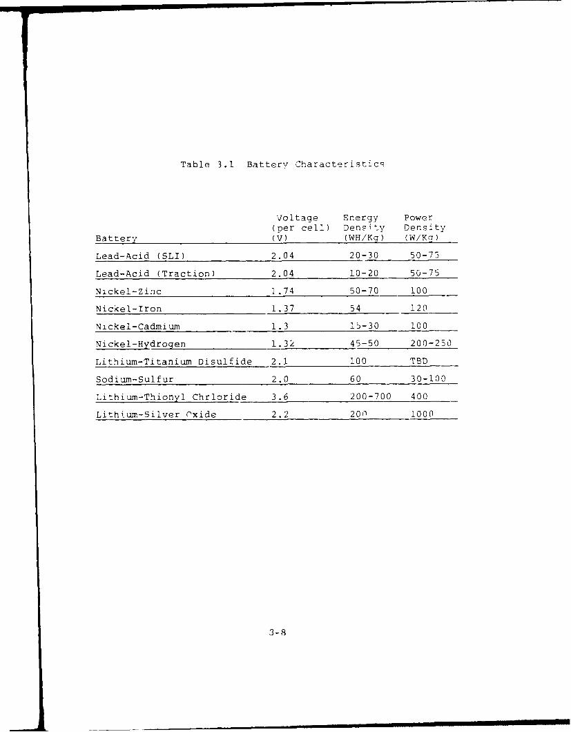
Table 3.1 Battery Characteristics
Voltage Energy Power(per cell) Density Density
Battery V) (WH/Kg) (W/Kg)
Lead-Acid (SLI) 2.04 20-30 50-75
Lead-Acid (Traction) 2.04 10-20 50-75
Nickel-Zinc 1.74 50-70 100
Nickel-Iron 1.37 54 120
Nickel-Cadmium 1.3 15-30 100
Nickel-Hydrogen 1.32 45-50 200-250
Lithium-Titanium Disulfide 2.1 100 TBD
Sodium-Sulfur 2.0 60 30-100
Lithium-Thionyl Chrloride 3.6 200-700 400
Lithium-Silver Oxide 2.2 200 1000
3-8
achieve sustained high pcwer outputs. Batteries are best
suited for short to medium term low power applications. Other
aspects that must be considered in battery applications are
stc-age, shelf life, activation, and safety in undersea appli-
cation.
Figure 3.1 shows a comparison of power system weight
for five possible candidates (gas turbine, fuel cell, diesel
engine, gasoline engine, nuclear) as a function of the opera-
tion time for a 10 kw system (Smith et.al, 1986). Note the
exponential increase in weight as a function of endurance
(time) for closed cycle systems. Table 3.2 (page 3-13) shows
the power-to-weight ratio, nominal effrciency, normalized for
a 10 kw system. The 10 kw requirement is an arbitrary value
selected to make this comparison. The curves in Figare 3.1
are computed assuming a gas turbine fuel consumption of 120
percent, and diesel engine fuel consumption of 80 percent of
the gasoline engine with a 14:1 fuel to air ratio.
Small self contained power systems for autonomous
vehicles required to operate at depths to several thousand me-
ters for several months are limited to a few choices. Only
the nuclear and fuel cell technoloqy offers the capacity re-
quired for long endurance operational requirement. Figure 3.2
shows tne power delivered to the water required for low drag
hulli oZ various displacements and speed requirements (Boretz,
1984). A one ton vehicle operating at 10 knots, requires 2.5
kw and is marked in the figure. Figure 3.3 shows the power
system's weight as a function of mission duration for various
sources required to provide 2.5 kw. Clearly, for long dura-
tion missions only fuel cells and nuclear power sources can
mOet the endurance requirements for extended missions.
3-9

Figure .. SvS ere,, V0i-t as U iUnction of operation time withexponential growth of internal combustion engine aeight(from Smith et al, 19861
LEGEDa a GAS TURB&Co = rLL j
*-GASOLOC ENQ9 CK-PL- NUQ.L&R
II
)TOT
//-,,°, -/ ,________________
* -77
POWF R k E VE L 2 5ki#[
31 ~ i~ WYL E,,~N
")oE 100NT11MO0H' - --
. . M LIT41UM THIONYL HORf- " - T / m TBATFRY (166 W h, hl
RANIN r CYCLE hGINE I
H 2 ()2 f U 1E L C E t L' ISO 'LJRATI()%
;I .' ' WEEK I 6 M 'EA
,2 * * " MISSION [)URFATION ,hr,
F i Compirison w(, n w,and V:] ct -Ch(mlion]
' t orag(, S '\St(,m,
,w ] -; | r . { . . S u h m f r s i h ] , f m ) wv ( r f ' r ( m R o , t /., I , 1 9 ,S 4
d ,,1i ' ' ( to) W :it,, "
,m1mmmmm rm m m imsmm I, I -a a 0] •• m
However, closed cycie diesel systems may provide an option for
larger vehicles.
The nuclear power plant is an indirect energy con-
version system, while the fuel cell is a direct energy conver-
sion system which offers very high efficiency (Table 3.2).
Boretz (1984, 1985) describes a nuclear plant based
on the organic Rankine cycle electric power system (ORCEPS).
Figure 3.4 is a schematic representation of this system. The
isotope heat source provides thermal energy to the boiler
which supplies a superheated organic working fluid to the tur-
bine of a closed Rankine cycle system. Table 3.3 shows the
characteristics of some candidate isotopes, and Table 3.4
shows the design parameters for a .5 to 2.5 kw system. An
alternative design (Figure 3.5) replacing the thermoelectric
generator (TEG) with a samarium cobalt permanent magnet (PM)
alternator would provide for not only propulsion but also sen-
sor electrical power requirements. This design improves
efficiency resulting in reduced isotope inventory and reduces
materials cost as operating temperatures are reduced from
18000 F for the TEG to 8000 F.
There are two commercial nuclear systems in the
planning stage. The Canadian AMPS which is exnected to be
available in 1991 in the SAGA-N vessel. The second is the TRW
ORCEPS system described previously for which there is no pro-
duction schedule available. Both systems would be capable of
producing 10 kw of power for at least 1000 hours of operation.
Fuel cells were originaly developed for the National
Aeronautics and Space Administration as power supplies for
soace craft. Many types of fuel cells are available commerci-
3-11

y99
CI
z
0 S2
-- ~ ~~ 0' -- -2

Table 3.2. The impact of Power-to-Weight Ratio on InitialPower System Weight for a Ten Kilowatt Demand(from Smith, et al, 1986)
System Power-to-Weight Nominal Initial SystemPatio Efficiency Weight
(kW/kg) I(%) (kg)
Nuclear 0.60 40 16.67
Gas Turbine 3. 30 20 3.03
Diesel Engine 0.55 35 18.18
Gasoline Engine 0.82 25 12.20
Fuel Cell 0.91 90 11.00
Table 3.3. Characteristics of candidate isotooesfromn Baretz, 1985)
Fttt T..-1717 P-210 GdP. C...-42 C.-244 P-3(EF
HALF-LFE 17 DAYS 138.4 DAYS 136.4 DAYS 163 DAYS 18 1 YR. 37.3 YR.
MODE OF DECAY KTA ALPHA ALPHA ALPHA ALPHA IALPHA
SPIC PO%FR (ftM 13.6 144.0 144 0 1200 2B.4 0.56(WArTS/GM4.SOTOPE IsP~aFIC ACIATY 445 31 313 29 30(COSWAMf
SPONTANEOUS RSSION - . - 7.2..ir 1.4aiIT 4.%1101HA1.F.UFE (YEAR)
RtAL FORMA METAL METAL RARE EARTH C-20~3 C-03 N02POLONIDE
SHELDIN. NEOUED MODERATE MINOR MINOR MINOR AODIERAT .J NOR
spEOac Pwi 2.1 140 73 90 2-4 0.4(WATTS/GM-FIAL FORM)
sPnanc WEIGKT 1. 00 0.01577 -0.030 0. W45 0. 9M 5.512(LS-FLINL ROL'KWT)
MEAT SOURC! FlJGKI NONE SNAP-29 Sk&P-29 SNAP-1i NONE SNAP-3AAPPUCAnlO"S OR OTHER I 9A
-19
KI PS/81PS
3- 1 3
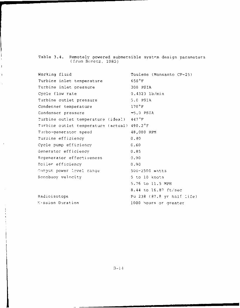
Table 3.4. Remotely powered submersible systcm design parameters(from Boretz, 1985)
Working fluid Toulene (Monsanto CP-25)
Turbine inlet temperature 650OF
Turbine inlet pressure 300 PSIA
Cycle flow rate 0.4323 lb/min
Turbine outlet pressure 5.0 PSIA
Condenser temperature 170°F
Condenser pressure -5.0 PSIA
Turbine outlet temperature (ideal) 447°F
Turbine outlet temperature (actual) 490.2 0 F
Turbo-generator speed 48,000 RPM
Turbine efficiency 0.80
Cycle pump efficiency 0.60
Generator efficiency 0.85
Regenerator effectiveness 0.90
Boiler efficiency 0.90
,)tput power level range 500-2500 Vtts
Sonobuoy velocity 5 to 10 knots
5.76 to 11.5 MPH
8.44 to 16.87 ft/sec
Radioisotope Pu 238 (87.8 yr half life)
'ssion Duration 1000 hours or greater
3-1 1
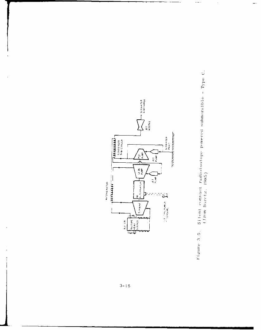
II
3-1 5
ally, the primary difference among them being the chemicals
used as oxidizers and reactants. Two examples of such cells
are the hydrogen-oxygen cell and the hydrazine-hydrogen
peroxide cell.
The ALSTHOM ten-kilowatt self-contained cell is a
hydrazine-hydrogen peroxide cell. It will produce full power
for a minimum of 500 hours, but weighs only eleven kilograms.
Designed specifically for use onboard submersibles, it was
tested onboard the vessel STAR 1. The major disadvantage of
this system is its excessive cost--hydrazine is approximately
$45.00 per liter, while a 50 percent solution of hydrogen
peroxide is $23.00 per liter. Thus, a hvdrazine-hydrogen
peroxide cell represents a substantial cost in both the con-
struction and life cycle use of the vehicle. Both chemicals
are considered to be hazardous. Hydrazine is toxic, flam-
mable, and highly reactive, requiring special procedures for
handling under any conditions. Hydrogen peroxide is a strong
oxidizer. It can irritate skin and eyes. It also requires
careful evaluation of its compatability for storage and hand-
ling when in the presence of other materials.
The second example of a fuel cell is the hydrogen-
oxygen system engineered for the DSRV-PCl5, but never install-
ed. This hydrogen-oxygen system will provide ten kilowatts
for seventy hours, but it weighs more than four tons. This
unacceptable weight addition is due primarily to the cryogenic
storage containers for both the hydrogen and the oxygen. In
addition, waste water produced by the system is stored onboard
the vessel. A similar system was installed onboard the vessel
Deep Quest, which completed nineteen dives with an energy pro-
duction of one-thousand kilowatt hours. Note that Deep Quest
3-16

is no longer listed as operational in the Manual of Manned
Submersibles.
Despite these problems, both the nuclear system and
the fuel cells are possible power sources for a submersible
with extended range requirements. An evaluation of these two
alternatives will help to determine which of these may be the
most appropriate.
Several factors need to be considered in comparing
nuclear and fuel cell power systems for autonomous vehicles of
the future. These are:
" Stage of development
" Complexity
* Size limitations
* Safety
* Reliability
" Life cycle costs
" Technology development risk
Fuel cells are a proven and established technology in compari-
son to nuclear systems. Furthermore, nuclear systems are reg-
ulated by international treaties, and their use as power
sources may not be possible for unattended ocean deployment.
The fuel cell is simple, relatively light, reliable and highly
efficient in energy conversion. Their life cycle costs would
be low compared to nuclear systems. However, the nuclear
system provides potentially greater endurance.
Energy Conversion Systems, Inc. (ECS), Canada,
specialists in small nuclear power zurce design, and the
3-17

International Submarine Engineering, Ltd. (ISE) have jointly
undertaken a program directed toward the development of a
proof-of-concept nuclear powered robotic vehicle.
The nuclear power source proposed for the subject
vehicle will use a fully developed and working reactor,
SLOWPOKE, which has been licensed in Canada for unattended
continuous full power operation. It is the only reactor in
the world so licensed.
SLOWPOKE consists of a non-pressurized convectively
cooled light water moderated, berylliur reflected reactor. The
core comprises the fuel cage and fuel elements with overall
dimensions of 8.9 inches high and 16.7 inches in diameter.
The reactor and energy conversion system to meet AUV power re-
quirements can easily be contained within the envelope the
size of a conventional torpedo. The original SLOWPOKE reactor
and its descendants have operated for approximately 36
trouble-free, full-power years. A complete SLOWPOKE system
sells for $650,000. An AUV equipped with such a power suoply
could make substantial underwater track sorties for environ-
mental and acoustic data acquisition.
A novel technique for the extraction of oxygen from
seawater is being investigated by Aquanautics, Inc. Mr. Steve
Carnavale (personal communication) indicated that the firm has
successfully extracted one-half liter of oxygen per minute
directly from seawater. Such an inexhaustible oxygen supply,
when combined with another fuel, can be used in a fuel cell or
combustion engine, to provide long-life power for military
marine applications. The company is currently working on
Phase II of a DARPA contract. This is the second step in
3-18
testing its technology which is ear-marked for propulsion of
an autonomous vehicle. This new technology will, if success-
ful, provide for longer-range endurance beyond that currently
available from batteries or stored oxygen and at a substan-
tially lower cost than nuclear power. The DARPA program
manager and point-of-contact is CDR Ralph Chatham.
3.5 Umbilical Tether Cable
A key tethered free-swimming ROV subsystem is the
umbilical cable that provides power to and communicaticns
with the ROV. Mission requirements strongly influence the
design and operational effectiveness of the ROV umbilical.
ROVs that tow the full cable at its operating depth requires
propulsion/power capabilities quite different from an ROV
system that uses a deployment cage. The ROV is then burdened
only with a tether extending from the cage out to its maximum
operational radius. There is little commonality in umbil-
icals, oarticularly for ROVs not of the same class or manu-
facturers production run.
Umbilical cable varies greatly from one vehicle to
another, some cables are positvely buoyant, while others are
negatively buoyant. Negatively buoyant cables may be made
less negative by the addition of flotation devices, but these
are cumbersome and add drag that must be overcome by the
ROV.
Most umbilical cables contain a strength member,
conductors for power, and communication conductors for con-
trol and data telemetry. They are all encased in a protec-
tive sheath of neoprene or polyurethane for insulation and
3-19
abrasion protection. Diameter of such unitized cables range
from 6.3 mm (0.24 in.) to 38 mm (1.5 in.). One to three
coaxial conductors are often used in addition to solid core
conductors. The longest umbilical in use is the U.S. Navy's
RUWS system cable. It is 6,858 m (22,500 feet) and transmits
all power, command and control functions, television and
sonar over a single coaxial cable through use of time sharing
and frequency multiplexing techniques.
Most conventional power cables are unsuitable for
use in temperatures below -10 0 C because of extreme brittle-
ness of synthetic rubber insulation. Either a low voltage,
natural rubber insulated cable especially manufactured for
low temperature or a validated substitute material suitable
for arctic extreme low temperature use and ice abrasion
resistance should be specified for any arctic ROV applica-
tions.
Fiber optic umbilical cables were first used for
ROV applications about 1982. This technology was incorporat-
ed into the umbilical cable for the Slingsby Engineering ROV
SOLO, in 1982. Fifty micron fibers with 125 micron cladding
allow for considerable data transmission expansion. An LED
system with frequency shift keying was adopted from other
commercial practices where it has proven to be very reliable.
Using fiber optic transmission, studio quality pictures can
be obtained.
Umbilical cables also serve as a lift member during
the launch and retrieval of an ROV. For large systems the
strength member is usually Kevlar, a high strength-to-weight
synthetic fiber. To reduce the size and weight of an umbil-
3 -20

ical, a separate lift line is substituted for the launch and
retrieval phase of an at-sea operation. Most cables are neg-
atively buoyant. Therefore, a length of broken umbilical may
exceed available ROV reserve buoyance, and carry it to the
bottom. To overcome a potential catastrophe a variety of
flotation devices are available for attachment to the umbil-
ical. Some of them also serve to reduce abrasion caused by a
cable catenary reaching the seafloor and to a degree it
reduces some of the bottom drag that must be overcome by ROV
propulsion thrust.
3.6 Acoustic Communication Links
Although untethered vehicle development is tending
toward full computer controlled autonomous operation, there
will remain periodic need for operator supervision of some
missions and communications between an operator and the
vehicle. However, acoustic communications using the Frequen-
cy Shift Key (FSK) method or other encoding techniques can
provide reliable means of two-way data communications between
the support platform and the AUV. Such a data link uses
advanced signal processing and error encoding techniques to
provide users with reliable telemetry at a data rate of 50
baud.
An acoustic telemetry system has been developed by
International Submarine Technology, Ltd., Redmond, WA, to
support the AUV ARCS for the severe multipath conditions that
it will encounter in the shallow-water underice arctic
environment. This system was developed for long-range,
medium-rate, full duplex digital data transmission in water
depths varying from 10 m, to 200 m. The system includes the
3-2 1
capability to overcome the Doppler shift generated by the
AUVs velocity. The system consists of a transmitter and a
receiver which may be used together for full duplex communi-
cations, or singly fcr one-way communications. A communica-
tions range of 4500 m is possible in the fcll duplex mode.
Greater range is achievable in the one-way mode. Communica-
tion was maintained at a distance of four miles ard at AUV
speeds up to 7 knots despite external noise and severe multi-
path interference at a non-arctic test sitc. The manu-actur-
er claims Doppler immunity to 8 kn'ts. Data race can be
varied to suit multipath conditicns. Available data rates
include 24, 50, 100 and 200 bits per second. From field
tests the system was found to provide a reliable 5) baud,
full duplex, synchronous link through water. Although acous-
tic systems lack the communication capacity achievable with
hard-wire or fiber optics it does offer a usef.l real-time
communications link with autonomous vehicles. This feature
permits data sampling to ensure that spnsor(s) are function-
ing and gives the operator an opportunity to make decisions
regarding vehicle maneuvers. Onboard data storage from add-
on sensors will have to be used to acnieve a greater data
set.
A vertical cone acoustic transmission system has
been developed for the AUV AUSS that can hrndle 4800 baud --
enough for good quality video signal transmission.
3.7 Television
The larger ROVs frequently have two or more televi-
sion cameras which are often mounted on pan-and-tilt units;
:3-22
this allows for increased viewing area, viewing different
scenes simultaneously, accommodation for a somewhat reduced
maneuverab4 lity in restricted environments, and redundancy.
Two cameras -re often employed as follows: one is fixed and
used by the pilot for navigation and maneuvering and the
second is mounted on a pan-and-tilt mechanism and dedicated
t- use by the customer (an engineer, scientist, etc.). Tele-
vision camera position cont:ol, as indicaed above, may be
accomplished by maneuvering the ROV. The position of
teievision cameras and irtificial illumination is important
to provide adequate viewing perspective and to reduce
illumination backscatter. Some manipulator systems include
an auxillary television located on the arm and close to the
work site; this serves to expedite manipulation of tools and
to partially overcome longer viewing under turbid water
situations. Manipulator operations are viewed and controlled
by a topside operator.
3.8 Lights
Light sources are independentiy housed ano are
available in power ranges from 45 to 1,000 watts. The rela-
tively high power requirements of lights must be accommodated
through the ur-ilical. Quartz iodide lights a-e most common-
ly used but mercury vapor, tungsten iodide and thallium
iodide lights are also used. The lights are usually located
to support both the operator's television and are located on
the bow of the ROV. To reduce the etfect of backscatter some
are mounted on extendaole or fixed booms or at off-center
locations. If still camera arrays are used for seafloor sur-
veys then the lightina may be directed down. Scrobo:;copic
3-23
light sources, usually in the 250 microwattsecond ranae, areuxsed withl a still camera.
3.9 Film and--Video Camera Recordinq
Documentation of underwater scenes and situationsis ofrten accomplished with a still camera (with strobe
,iehTtinq) Video camera recording can be accomplished on-boar~d Titn ' Ov (l-imited to one cassette) or at the- surf ace.Tt-e q'uilitiy of: video cameras and recordinq i S imorov4ing
atiivand will like-ly replace most film svsttems, r, cecI deoC svst-m's mr'-)v d e valued real-time v:-w in q and
-ffct ' e rformance ct ~sf U wor cv am n7
* - rnin em~et ioin tne ava iLability o4r imeF -r mrr5 --)-' '-i can ce -c)aced] .-nd operatel o% 9
a r- ~ i: oia rlwio T d iec
7cinS in,' ' - rm aoi. its ,umnrsion!- a's ,rm ' tors Prnmq ',velono -3: its bil it'. to OosItion
-4 , 3i ~ Co.) i soce.There ar t V'uoe
T"~~~ I~ cjirz : i ,,irrcntly used on ROV-
I 'l ~dLimite _d motions R0'"m) C nrit'r c, I ' t.h e ma i pL c la o rs _I ni
S nori -c'ompl 1 -,1h'2( *V~ togolei r -: ic-k T,, p c.i wcrK k ca ab i I
.3''-i. nd as -i r'-, ra im -i ev
-~ri r1o i ()n~ s dqr-q sftree-
~~~~ In '

joy stick. Typical work capability includes
debris removal, simple power tool/cleaningtasks. Task performances are relatively long.
3. Master/slave manipulator with force feedback.This type is also known as a spatial correspon-dent manipulator system since the master/slaveunits operate in synchrony and the two manipu-lators are geometrically similar. Master-slavemanipulator system technology has not beenwidely adopted. Typical work capabilityincludes complex tasks -- drill, tap, assemble,disassemble, non-destructive testing.
The soectrum of tasks that can be accomplished by a remotely
operated manipulator, for the most part, f; 1 in these
qeneric classes:
recovery of objects,
2. simple assembly and disassembly operations,
3. making and breakinq -onnections (hoses, cices,electrical lines), and
4. docking.
f tne above tasks, it is frequently possible to recover
...j..s, and in some cases to achieve dockinq with maniou-
lators, with less than six degrees of freedom, but the other
tasks require the full number of motions unless supplemented
nv vehicle mobility.
'.'s ion is the mos t important sensing support for
remoty located manipulator onerator. For example, ,t
s et imatfd that 70% of the iseul sens in caa bil ity for a
lore, fdback manipulator operator comes rom optical -Iw-
.rw. As a comprehensive explanation on viewinq is not pos-
sible here, it is important to stress that viewing is depen-
dent on viewing angle, water clarity and acceptable levels of
backscatter (particularly when artificial illumination is
used). The performance of some tasks makes it desirable to
have three active television cameras available:
* a fixed wide angle camera for an over-all viewfor the operator,
* a camera on a pan-and-tilt mount with a zoomlens for selective close viewing,
* a camera manipulator either hand held or fixedon the wrist or forearm.
The number of firms manufacturing manipulators for
underwater aoplications is adequate for the buyer to select
an off-the-shelf unit or to have one customized from avail-
able components.
Requirements for tools to be placed or operated by
the manipulator "hand" have been identified for most generic
functions. The "hand" or terminal device of most anthro-
pomorphic manipulators is usually capable of gripping and
rotating. Simple, light load tasks can be accomplished
with this terminal device. In many instances a specialized
tool is more appropriate and its power requirements are fre-
quently met by a dedicated power source <electric or
hydraulic). Accessory tools include water jets, various
Kinds (f cutters, impact wrenches, stud fastener auns and
attachmen<, devices.
3.11 ROV Propulsion/Maneuverability/Self Noise
There is a nearly universal use of electric driven
propellers for propulsion. Only a few systems have water
jets. Drive motors may be electric or hydraulic. The larger
vehicles normally use a shrouded Kort nozzle propeller. Thiq
provides both greater efficiency and protection against pro-
peller contact damage and ingestion of debris. The number of
propulsion units per vehicle is dependent on desired levels
of maneuverability and total thrust with three thrusters con-
sidered minimum.
Six degrees of motion are almost a standard
requirement for tethered swimming ROVs. Three are transla-
tional: thrust, heave and slide or sway; three are rotation:
yaw, pitch, and roll. Reversible electric motors provide
reversible thrust and the combined maneuvering forces allow
for three-dimensional movement without the forward motion
required by rudder controlled vehicles.
3.12 Operating Depth Rating and Horizontal Range
The majority of commercial ROVs have a design oper-
ating depth of less that 330 m. However, several Navy ROVs
developed as R&D vehicles have been influenced by anticipated
Navy missions And have opetating depth ratings to 6,000 m
(98% of the seafloor can be reached with this capability).
Several commercial ROVs could be immediately qualified for
deeper depths by the addition of a longer umbilical cable as
all other components aire compensated for full depth opera-
tions.
Horirontal range capability has not been a pnrticu-
larly important parameter for tethered free-swimming FOV
applications in the offshore oll and gas industry. In most
industry operational scenarios the ROV can be effectively
employed within a short horizontal excursion radius of the
site; either from the launching platform or from a deployment
cage. Under-ice mission scenarios are expected to require a
longer horizontal operating radius. Cable technology is not
expected to change significantly in the next decade to allow
for major growth in ROV horizontal operating range capabili-
ties of tethered free-swimming ROVs. Systems that can oper-
ate effectively on a self-contained power source and light
weight fiber optics cable for command/control/and data telem-
etry would be more suitable for scientific acoustic research
functions. The present maximum horizontal range is less than
500 meters.
3.13 Speed and Thrust
Tethered ROVs, as a class have speeds ranging from
0.5 to 4 knots with the average approximately 2.5 knots.
Te:hered free-swimming ROV propulsion dtiigns are dedicated
primarily to maneuvering fuinctions and to overcoming reason-
able ocean currents, not speed. The capability to reach and
stay at the work site in order to complete specific tasks
expeditiously is fundamental to commercial and military
applications.
Vehicle speed performance is a result of umbilical
size, length of free umbilical, ocean current profile,
vehicle hydrodynamics, thruster horsepower, rpm and propeller
characteristics. These parameters are interrelated. In
general, the system drag equation is umbilical doinated.
This factor influenced the design and adoption of a deploy-
1II8
ment cage for many systems. The primary cable length and
lift support are in the cable connection between the launch/
retrieval winch and the deployment cage. The ROV is thereby
relieved of all but the short and lighter design umbilical
tether between the ROV and to the deployment cage.
3.14 Acoustic Subsystems
Acoustic subsystems have come to provide capabili-
ties to support not only the operations of ROVs, but also
contribute significantly to their performance specifications.
The descriptions here are brief and are included to indicate
the range of subsystems that have been found useful to sup-
port ROV operations.
Navigation and Sub-Sea Positioning
ROV navigational requirements are vFried and the
number of commercial acoustic systems to meet them are many.
Most have emerged to meet specific ROV requirements. Re-
quirements for an ROV navigational system are directly tied
to the ROV operational effectiveness. 'ihe spectrum of opera-
tional requirements has widened greatly in the past decade,
creating the need for task oriented and dedicated ROV track-
ing and navigational systems.
The classical acoustic depth soundors are used to
determine vehicle altitude above the sea floor and distance
below the sea surface when mounted in an upward looking
direction.
3-29
The following characteristics are common to most
ROV field operations and are to be considered in the naviga-
tional equipment selection process.
1. The surface control station equipment must bedesigned to withstand the marine environment. Thisincludes the consideration of platform motion andvibration, exposure to salt and sea air and sub-stantial temperature and humidity variations (a
particular concern in polar regions),
2. The surface platform type may vary dramatically.Equipment, to be effective, must be readily trans-portable to different sites and used on differentplatforms; surface vessels, fixed platforms, icecanopy and ice islands, etc.). The equipment needsto be portable, easy to install and designed to beused from both small boats and large platforms.Mobilization and demobilization time and costrequirements should be minimized.
3. Availability and performance must be reliable andconsistent. The operator has to depend on avail-ability, repeatability and reliability in perform-ing to required standards. The equipment must alsobe designed to operate across the spectrum of oper-ational depths and geometries.
4. The system must be simple to use and maintain.Personnel turnover, commercial or military, andlack of experienced operators dictate the need forsimplified operator interface and maintenance.
5. Proper position display should give the operator aline of sight between the vehicle and another sub-sea point, reducing the time it takes to travelfrom point A to point B.
6. By using additional beacons to mark subsea loca-tions, the time it takes to relocat- a site can bereduced consideraoly, especially when visibility ispoor.
3-3o
7. For initial site location where there is no acous-tic marker, an alphanumeric and graphic readout inrectangular (X and Y) coordinates provides theinformation necessary to run an efficient gridsearch.
8. If the vehicle umbilical is severed, the system'sreal-time range and bearing information signifi-cantly reduces recovery time and improves the prob-ability of success.
Sub-sea positioning, navigation, tracking and relo-
cation of ROVs has evolved through long baseline, short base-
line, to ultra-short baseline. Each of these techniques is
applicable to arctic requirements and researchers will likely
find use for each of them at one time or another.
The earliest systems were known as long baseline
and involved the deployment of several transponders on the
seafloor, accurate relative calibration, then fixing by slant
range measurement by interrogation from a single transducer
mounted on a surface vessel hull. These systems required a
significant amount of subsea hardware, frequently lenqthy
calibration, and a highly trained operator -o achieve valiJ
data.
In the 1970s the short baseline technology was
adopted. This consisted of a subsea transponder beacon and an
array of at least 3 hydrophones mounted in an orthogonal
array on a vessel. ROV position was calculated on pulse
arrival angle and time.
In the mid-70s the ultra-short baseline system was
introduced and it has become the most widely used technoloqy
for ROV navigation. A single sub-sea transponder is requir-
:3-:31
ed. A transducer is used in conjunction with a multi-element
hydrophone mounted on the support vessel hull. Again, arriv-
al time and phase angle are measured for each element.
Phase differences in the horizontal and vertical planes re-
sult in measured azimuth and slant angle. Given a known
vertical separation from the beacon and the hydrophone, range
is automatically computed by triangulation. Angular measure-
ment accuracies in both instances are typically plus or minus
1 degree. Two inclinometers are included in these systems to
account for phase difference errors induced by ship move-
ment.
Transponders for acoustic markers and underwater
vehicle positioning are available with remote release, dual
command relay output, remote transducer and responder opera-
tion.
Sub-sea positioning, navigation, tracking and relo-
cation systems are available from several commercial sources
and custom systems can be acquired from most of these firms.
For example, 80 to 90% of today's ROV navigational require-
ments can be satisfied with a system such as HYDROSTAR, manu-
factured by Honeywell, Inc., Marine Systems Division
(Seattle, WA). The Honeywell RS/900 can handle more sophis-
ticated and demanding operations -- complex geophysical sur-
veys, deep-water facility installations, and deep-water ROV
operations. The RS/900 operates simultaneously in both long-
baseline and short-baseline modes which provides maximum
flexibility and optimal accuracy over full-ocean ranges.
Several other manufacturers offer navigation and sub-sea
positioning systems to meet a variety of ROV needs.
3- 32i
3.15 Obstacle Avoidance/Search and Survey Sonars
Obstacle avoidance/search/survey sonars are avail-
able for ROV applications. As these sonars involve different
principles of operation each is described.
Fixed Narrow Beam Sonar
Fixed narrow beam depth sonars have been used on
manned submersibles and submarines for many years. This
simple pulse sonar has been mounted on ROVs to detect near
field obstacles and/or to identify positioning clues. The
range requirements are modest, the physical size of the
transducer is small, and the operating frequency is normally
about 50 kHz. However, the fixed field of view, characteris-
tic of this approach, limits its usefulness.
Parametric Sonar
The parameteric sonar uses two transducers operat-
ing at a slightly different frequence to generate a differ-
ence frequency by wave interference. Though this process is
very inefficient (requiring typically 5 to 10 kW at two high-
er transmit frequencies) its main benefit is that the differ-
ence beam (at lower frequency) is essentially identical to
that o: the two high frequency beams. The beam can, there-
fore, be very small for a given transducer size. Longer range
is possible with this technique due to the lower adsorption
losses at low frequencies.
2-33
Narrow Beam Mechanical Scanning Sonar
To gain more forward acoustic viewing area a narrow
beam mechanical scanning sonar can be used. A wide vertical
beam (250 to 500) can be used to effectively decouple vehicle
motion in this plane; the horizontal beamwidth is normally
kept narrow (1.40 to 20) to provide azimuthal resolution.
At operating frequencies of 100 kHz to 500 kHz the transducer
size is smaller and target resolution good (88 to 213 mm).
This type of system can be used for obstacle avoidance,
search, and classification depending on the specific design
parameters. Slow coverage rate is its most serious drawback.
Each bearing must be sampled for the acoustic transit time
out to maximum range and back. The h igher the bear ing
resolution and/or acquisition range, the slower the data
rate. For example, two commercially available systems
advertise 58 seconds for a plus or minus 90' scan at a 400
meter range setting and 10 seconds for a plus or minus 900
scan at 100 meters, respectively. The outout data
displayed on a Plan Position Indicator (P.P.I.). It must be
recognized that the uncompensated vehicle motion during slow
scan can significantly distort the output. As
detection/classification is most often a process of relative
comparisons rather than absolutes, distortion can become a
significant liability. Additionally, in a generic sense
mechanical scanning systems are Qften unreliable.
Continous Transmission Frequency Modulation Sonar
Continuous transmission frequency modulation (CTFM)
sonars are a variation of mechanically scanning sonars. CTFM
converts range (time) to the frequency domain by transmittinq
a continuous sawtooth frequencl slide pulse. This type of
sonar has been effectively used on manned submersibles and
3-:3)
ROVs as an obstacle avoidance sonar because of its small size
and relatively good target detection capabilities.
Phase Comparison Sonar
Phase comparison type sonars process the phase
information inherent in a return to determine bearing. Time
of arrival, phase or correlation interval measurements are
made on two or more wide beam elements to determine bearing
of the return. Data rate is improved over simple mechanical
scan systems in that large bearing slices are processed in a
single, two-way acoustic travel time interval. However,
bearing resolution is proportional to the signal-to-noise-
ratio and the processor may become confused by numerous
simultaneous targets of comparable amplitude but different
phase typical of interface returns.
Side Scan Sonar
Side-scan sonar looks to the side and is very
effective for seafloor search and identification. It is
usually towed by a surface vessel. The system operates on
the concept of displaying interruption in reverberation
caused by the acoustic target shadow. The length of the
shadow can be used to estimate the vertical relief of the
target. The length of the tprget can be determined by the
along track shadow assuming vehicle speed is known and side-
lobe detection is precluded. The horizontal image build-up
requires vehicle motion, and one "fly by" may be inadequate
to determine geometries. Distortion will be experienced if
vehicle attidude and/or speed changes occur. ROV7/AUV speeds
:3-3 5

are in a range highly compatible with side look sonar per-
formance characteristics.
Multi-Beam Sonar
Multi-beam sonars operate on the principle that a
multi-element fixed array can be electronically steered in
bearing. Duplicate electronic steering networks generate a
number of adjacent preformed beams to cover a given arc.
Electronic scanning of these fixed beams, within the transmit
pulse width, achieve complete bearing coverage in the time
interval for sound to travel to maximum range and return. In
low resolution sonars with the beam widths that might be used
by ROVsAUVs for obstacle avoidance, electronic focusing is
not required and the spatial separation of the beams can be
accomplished by a circular array of transducer elements.
Although multi-beam sonars have not been applied to ROV plat-
forms the virtues of these systems are important to gaining
swath sweep survey capability. Even though there is a lot of
parallel channel redundanc;, its main disndvantage is tne
requirement for a fair amount of electronics. Recent and
projected advances in solid state electronic technology is
expected to reduce this disadvantage. The multi-beam
approach has been employed extensively by the U. S. Navy and
NOAA for bathymetric survey vessels. Multi-beam has tne
potential of being used both in the vertical and horizontal
to produce bottom survey data and obstacle avoidance for the
vehicle. Also in the vertical, an upward directed multi-beam
could orovide underice topography data.

F
Scanning Profiler Sonar
It is not unusual to have sevecely occ~uJd ootical
viewing conditions around a bottom-c awling ROV. zx high
resolution, high speed, scanning echo-sounde, has been
developed by Ulvertech, Ltd., Cumbria, England, that provides
real-time graphic or video displays aid diqit-l magnetic tape
recordings. This system (the Dual Scanning profil=r) shows
the position cf a pipeline or cable burial and any trench
erosion or scouring that has taken place. Phe acquired
information is a composite eisplay coF two scanning h ads.
Using a computer the data obtained can be prepared for plor-
ting cross-sections and depth presentations. Outlines of
pipelines, cables, dredged areas and the condition of -truc-
tures are features of this system. Depending on water con-
ditions, maximum range of the system is 50 m oer channel.
3. 1b Buoyancy
Most ROVs are desianed to have sliant -osi -ie
buoyancy at all times. Thi:< arangement provides serti7al
stability and assists a venicle's return to the sur n
the event of a oower loss. Svnta- '- foam is used most
instances to providE static buoyatncy at all oreratin< depths.
Syntactic foam can easily be formed (cast or machined)
conformal shapes to provide some hydrodynamic ciean nes.
For additional payflad capacity additional svntactic foa:r i;
be easily added to the vehicle.
3.17 Remote Control Station
A substarntial amount of support equipment is nee~i<<:
during ROV operations involving the larger vehicle svstms.
A typica' control/display station contains video disnl 'Vs,
A"231s 7269 fff : c To p,. aUJNCLASSIFIED I a -NtLi~
2r 2. 5r * L1.0V
video recorders, navigational displays and plotters, naviga-
tion and positioning equipment, communication links to the
launch/retrieval team, power supply and control. The con-
trol/display station provides information for both the opera--
tor and the user.
The control/display subsystem incorporates a spec-
trum of sensors, controllers, displays, and data recording.
The degree of complexity of the control/display system is
strongly influenced by the number and difficulty of functions
that must be within the capability of the ROV and the human
operator.
Computer driven navigation displays, in both black-
and-white and color, provide information on the relative
positions of the surface platform, the ROV, and various
targets or beacons. These displays offer the operator an
over-view of the whole scene. Consequently, maneuvering to
tne work site and to other locations within the radius of the
ROV is greatly simplified.
3.18 Deck Space
Surface support platforms normally do not include a
dedicated or full-time ROV in its inventory. To accommodate
the ROV system components that are to be located on a surface
support platform, portable vans are outfitted for a deck
installation. The vans also serve as transportation con-
tainers for the entire system. Several vans may be used to
keep the size and weight of each unit reasonable for a varie-
ty of logistics transport methods -- land, air and sea. The
vans allow for the manufacturer and operator to prepare the
3-38
system for field use before it goes to sea. At sea the vans
serve as the control/display center for the ROV operator;
other vans house power sources, spares, personnel housing,
and repair shop. There is a wide variety of van sizes and
area space/volume associated with the present family of
vehicles. Deck tie-down accommodations are available, or can
be readily installed, for the vans on most surface support
platforms. The vans are usually specially reinforced and
outfitted for deck loading.
3.19 Launch/Retrieval
The wide range of ROV vehicle weights (80 to 5,000
kg) results in a broad spectrum of launch/retrieval require-
ments. There are ROVs that can be launched and retrieved
by one person. The majority, however, are of a size and
volume that require mechanical assistance. Most are lowered
over the side of a support platform by a stiff-legged boom
crane. Most surface ships are equipped with a boom whose
length is equal to or greater than its freeboard. This
feature allows for a launch/retrieval that can be kept from
slamming into the ship's side during a severe roll. It is
quite effective when the ROV is close-hauled to the tip of
the boom. An alternative method is launch/retrieval by a
stern-mounted A-frame. A-frames are common to most oceano-
graphic research ships and serve to lower relatively large
loads over the side. However, tethered ROVs are vulnerable
to entanglement of the umbilical cable in the ship's
screw(s).
To improve safety most ship operators prefer to
have the ROV launched and retrieved alongside so that the
3-39
operation can be observed by the ship's Master. Because
operating ROVs from surface platforms is a relatively new
experience for most Masters it is important that the required
coordination be practiced extensively.
Many vehicles are both launched and retrieved using
a strength member other than the umbilical cable -- even
though the umbilical cable might be designed to have launch/
retrieval capability. Repeated use of an expensive umbilical
is usually avoided to gain extended umbilical service life by
relieving it, whenever possible, from the rigors of repeated
launch and recovery duty. The air-water interface can often
produce extraordinary stresses that can be tolerated better
by final lift strengih members. When launching, a quick
release hook is used tiat is tripped (released) by a lanyard
on deck. For retrieval some operators prefpr to zn.ever the
vehicle on the surface to a point where the lift line hook
can be attached from a long pole aboard the ship. The
vehicle is then quickly retrieved to this point where it is
±ocked to the crane boom and then swung aboard. In some
instances an auxillary lift line can be married to the umbil-
ical cable. When it reaches the deck winch the strength mem-
ber can be used to bring the vehicle aboard. This procedure
requires a second winch or windless for the lift line.
Most ROV systems use a drum to store the umbilical
cable. In some instances, the cable is laid out on deck or
within a suitable container. In other designs much of the
large umbilical cable is housed within a deployment cage.
The deployment cage serves then as a clump to carry the ROV
to depth. The ROV swims clear of the deployment cage towing
a much lighter weight cable to its maximum radius. Using
3-40

this method the deployment .age and attached ROV enter and
leave the water as an integral unit, thus obviating some of
the difficulties associated witL handling the more delicate
ROV alone.
Although a ship's launch/retrieval equipment can be
used it is usually more efficacious to have a launch/retrival
system designed specifically for each vehicle. Large ROVs
benefit from a special lift compensation system integrated
into tne design of a handling system. Such systems are of
benefit not only during the launch/retrieval events, but also
while the ROV is deployed. A compensation system provides a
marked reduction in vertical motion that significantly
relieves the operator of having to make frequent vertical
position adjustments. Nearly zero vertical motion control
can be achieved by hydro-pneumatic motion compensation
systems. A secondary boom angle signal can be incorporated
tnat serves for boom centering and active cushioning near the
stops.
A motion compensation launch/retrieval system was
developed for nandling the U. S. Navy RUWS. It is capable of
handing 7,010 m (23,000 ft) of umbilical cable. The launch,
tending and recovery of the RUWS lift package requires the
use of three separate modes of operation of the Motion Com-
pensation Deck Handling System (MCDHS).
1. Stiff boom mode - This mode permits operationof the boom as a conventional crane and is usedfor all deck handling work. This mode is alsoused for handling the vehicle/PCT package atthe surface of the water during launch/retriev-al operations when high boom tip speeds arerequired.
3-41
2. Passive mode - This mode is used after launchwhen the payload is submerged over 61m (200ft). It is used for motion compensation in SeaState 2 or Less and also serves as the powerfailure mode. In this mode, the boom is solelysupported by the hydro-pneumatic accumulatorsthat act as pneumatic springs.
3. Active mode - This is the mode generally usedwhen the payload is sub:merged over 61 m (200ft) in Sea State 3, or higher. In this modethe boom tip speed is minimized which reducesthe dynamic load on the primary umbilicalcable. The MCDHS permits worK operations inrather severe weather conditions and Sea State3 and Sea State 4.
It is the add-on sub-:ystems that provide much of
the work capability, operational effectiveness and versatili-
ty needed to meet specific requirements. Using state-of-the-
art sub-systems it is possible to configure an ROV to meet
many scientific research requirements. The following sub-
systems are now available from U. S. commercial sources:
Obstacle avoidance sonarGyrocompassDepth sensorAltitude sensorCurrent meterAcoustic velocimeterCable tracking systemsTransponder/interrogatorTransponder/responderSide scan sonarConductivity potential probeTransponder place/replacement toolHydraulic tool packageStill camerasVideo camerasFlood and strobe lightsFiber optics3-function grabber
3-42
7-function manipulatorsHigh pressure water jet (cavitation jet)Low pressure jet for silt removalAlignment measurement toolSpecialized lifting toolsHydraulic power packConductivity-temperature-depth sensorSound velocitypHRedoxOxygen sensorCorrosion potential monitorSpecific ion sensorsRadiographic instruments
Oceanographic instruments, available as off-the-
shelf units, can be installed aboard most ROVs as extra pay-
load. Buoyancy can be added to compensate for items that
exceed the normal ROV payload. It is fortuitous that many
newer versions of oceanographic instruments have built-in
recording capability for unattended use. Consequently these
systems can be mounted on an ROV quickly and without concern
for telemetry links or power connections. However, oceano-
graphic sensor telemetry requirements can be readily accommo-
dated by most ROV vehicle umbilical cables without modifica-
tion.
3.20 Personnel & Training
Personnel destined for operating an ROV in polar
regions need to be adequately prepared for the rigors of the
environment. Personal gear and a knowledge of the hazards to
surviving in the Arctic are covered here in direct relation-
ship with the special requirements of effectively operating
an ROV system. If the ROV crew expects to enter the water as
divers they should acquire a copy of "A Guide to Polar
3-43
Diving" 1974, by W. T. Jenkins, Naval Coastal qystems CeiLer,
Panama City, Florida.
ROV control stations vary from a unit the sizc 3f o
suitc.ase to a fully enclosed, temperature regulated van
designed for that purpose. However, all systems require some
human involvement for launch/recovery that will take them out
into the rigors of the weather and climate. Clothing design-
ed for protection against cold inherently means some bulk.
Bulky mittens markedly reduce manual dexterity when small
items require manipulation, e.g., knobs, switches, toqgles
and latches, etc. ROV systems destined for employment in
arctic regions should be appropriately equipoed to allow a
"well dressed" operator tD handle metal objects and to actu-
ate the full range of items necessary to operate an ROV
system.
Crew size and qualifications to operate ROVs varies
greatly according to the ROV system size, complexity and
operational requirements. Sustained on-site operations, such
as those associated with emergency search, recovery, and
rescue that involve 24 hour operations and rotating crews
require large well trained crews.
The level of stress varies greatly with mission and
function. "Flying and looking" is not considered stressful
and operator endurance is not severely taxed. In contrast, a
live boating survey that requires precision navigation over
long distances where almost constant support platform and ROV
maneuvering are involved causes fatigue to set in more rapid-
ly. A study by Busby found that the operators felt they
could effectively operate their ROVs between one to four
3-44
hours depending on the difficulty of the operation. inder
stressful conditions the average effectiveness time was about
one and one-half hours.
Operator training, until recently, was accomplished
by operating available systems and developing skills through
trial and error under the supervision of an experienced oper-
ator. Recently, International Underwater Contractors, Inc.
has established a formal course and a shore facility specif-
ically for training prospective ROV operators. This type of
training is expected t-) reduce the on-the-job training
methods that sometimes roquired six to twelve months. In
addition, the training facility is expected to alleviate the
personnel shortage that developed during the rapid build-up
of the world inventory of ROVs.
3.21 Operator Training
"Flvinc" an ROV in benign conditions (calm, clear
water where there are no hazards) is relatively easy and
satisfactory performance can be achieved by a neophyte in
less than an hour. When requirements for precision piloting
and accurate navigation are added then the time to develop
proficiency is markedly increased. Many scientists prefer
hands-on operation of their data acquisition systems and this
is feasible with the smaller ROVs. However, larger more com-
plex ROVs will require an experienced operator.
Formal, customized operator training is the most
expedient means to quickly gain maximum field proficiency
from ROV operator teams and for the safety of both personnel
and equipment. The field application of larger ROVs involves
.. J - | .2
a multiplicity of actions that must be accomplished simultan-
eously and requires experienced individuals for each.
Accordingly, a team of individuals is usually required to
support the operator, e.g. launch/retrieval deck operators,
navigation control, data monitoring, and vehicle operation.
The team approach is likely to be required for meaninaful
scientific investigations -- particularly under the artic ice
canopy.
Technician Training
Prudent planning for ROV/AUV operations in the
Arctic will include personnel trained tc maintain and repair
all ROV systems. Most available ROVs have been well tested
and reliable performance can be expected frum each sub-
system. However, field investigations are likely to be
jeopardized should any one of the sub-systems not be func-
tional, e.g., the navigation system. Technician assistance
'_knl q I -k- -- 'I h I - 'l-7 th- 1 --- 3rnd cther instru-
ments that are tc be carried by the vehicle.
Training Proqram
ROV and AUV operators and technicians should have
training in the following areas:
1. Vehicle design and performance characteristics.
2. Vehicle subsystems (structure, ballast, propul-sion, electrical/electronics and hydraulicsystems.
3-46

3. Tools, sensors, and scientific instrumentation(installation, operation and maintenance).
Examples: manipulators and their work toolpackage, video, pan and tilt, still camera,conductivity-temperature-density sensor, magne-tometer, water current, sunars, etc.
4. Controls and consoles. Pilot's console for"flying" the vehicle and manipulator operation,naviaation console, equipment status console,video and other real-time displays, communica-tion links.
5. Power distribution. Vehicle propulsion andsupport systems electrical/hydrauIic source(sand distribution. Power source(s), launch.retrieval systems, tether management system,connectors, slip rings, and power distributionconsoles.
6. Umbilical-tether cable(s). Internal design,repair, and maintenance of tethered vehiclesystems. Operational procedures, umbilicalmaintenance, waterproof field splicing of hard-wire and fiber optics, connectors, slip rinoassemblies, and performance characteristics.
7. Acoustic navigation. Operational applicationsfor shortbase, longbase and other acoustic nav-igation devices available for navigation andsurveying.
8. Handling systems. Instruction on controls andhydraulic functions of handling systems forlaunch and retrieval.
9. Team operations. Definition of functionsrequired to effectively operate a specificsystem. Indentification of organization andmethods involved in team operations.
10. Project definition and requirements. Specificindoctrination regarding project objective,data acquisition requirements, logistics sup-port needs, special team knowledge and organi-zation arrangements.
3-47
11. Operational considerations. Detailed instruc-tion in normal ROV procedures and methods. Forexample: mobilization, demobilization, ore-post dive system procedures, launch/recovervprocedures, platform support, ship support,navigation/'posistioninq communications network,data logging, spare parts, transporation anifield station logistics, preparations for colJweather operations.
12. Safety and emergency procedures. Protocols robe used to maintain maximum safety for person-nel and equipment. Emergency protocols to beused that include unique proc-idures for han-ling emergency situations unique to the ar-ti.iregions.
13. Pilot training. Hands-on traininq for oas>:POV piloting which is augmented with trainI7nfor soecific scientific arctic ooerations.
14. Scientific projects. Customizing in ROV nLar-form to support specific scientific nrojectsthat includes sensor and instrumentation add-ons, specific navigational requirements,"flignt" plans, data volume and recordino, ta-aprocessing and display, sensor and instrumen'ti-tion maintenance, logistics support platforms.
15. Legal requirements. Identification of permitrequirements and OSHAiU. S. Oov-rnment insprec-ion requirements, including authorization to
operate in foreign waters.
Formal RO Operator/Technican training is now
available year-round from commercial sources. The Interna-
tional Underwater Contractor's full-time standard ROV Pilot
Technician course involves 8 weeks to fulfill requirements
for entry level ROV positions. All fundamental and contribu-
ting skill relating to the planning and execution of commer-
cial ROV operations are covered in this course. Graduates
are qualified to work the entire spectrum of commercial ROV
3-18
operarions such as supcortinQ exploration, constuction,
inspection, maintenance, and salvage.
3.22 Guidelines for Selecting ROV Svstems for Arctic
Apolications
Anoendix 3 contains = detailed descrintion of most
ivaijable RCVs. For many arcric applications the smaller
jnits provide the necessary capabilities and keep the logis-
tic requirements within acceptable limits.
The following factors must be considered:
* Cost Effectiveness• Safety* Personnel Requirements* Task Requirements* MobilitySTminching Systems* Guidance Systems* Logistics SupportS"'ork Capability--operational reliability and wcrkability are the key
The smaller ROVs can be mobilized and transported
to the ice by available aircraft (e.g., Twin Otter). Theyca be moved by sled across the ice and do not require large
enclosed structures or ice entry holes. The oayload capacity
is satisfactory for many oceanogranhic and acoustic systems.
Multiple sensor/instrumentation array installations are
feasible. Self-contained oceanographic sensors can be added
and removed from the ROV to accommodate changes in data
acquisition needs and to serve more th-n one investigator
during a field operation period.
Some of the potential candidate PrV systems are
compared in Table 3.5
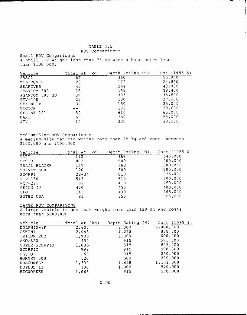
TABLE 3.5ROV Comparisons
Small ROV ComoarisonsA small ROV weighs less than 75 kg with a base price lessthan $100,000.
Vehicle Total Wt (kq) Depth Rating (M) Cost (1985 $)RASCL 67 360 55,000MINIROVER 23 122 24,850SEAROVER 40 244 40,000PHANTOM 500 28 152 28,400PHANTOM 500 HD 39 305 36,800RTV-100 25 100 27,000SEA WHIP 32 150 25,000VICTOR -- 183 28,600
SPRINT 101 52 610 65,000DART 67 360 95,000JTV 10 200 20,000
Medium-Size ROV ComparisonsA medium-size vehicle weighs more than 75 kg and costs between$100,000 and $500,000
Vehicle Total Wt (kq) Depth Rating (M) Cost (1985 ))ART 112 369 140,000HYSUB 802 900 200,000TRAIL BLAZER 135 360 500,000HORNET 500 120 500 200,000SCORPI 22-34 610 335,000RCV-150 545 610 200,000RCV-225 82 410 160,000RECON IV 410 450 400,000UFO 145 430 266,000SUTEC USA 85 350 165,000
LARGE ROV COMPARISONSA large vehicle is one that weighs more than 120 kg and costsmore than $500,000
Vehicle Total Wt (kg) Depth Rating (M) Cost (1985 $DOLPHIN-3K 2,600 3,300 5,000,000GEMINI 2,045 1,250 875,000TRITON 202 1,905 1,000 600,000ASD/620 454 915 591,000SUPER SCORPIO 1,635 915 805,000SCORPIO 998 915 590,000PLUTO 160 915 230,000HORNET 500 120 500 200,000DRAGONFLY 1,590 1,828 1,102,000DUPLUS II 300 1,000 520,000RIGWORKER 1,065 915 570,000
3-50
4. THE ARCTIC ENVIRONMENT AND ROV OPERATIONS
4.1 Introduction
The arctic remains a difficult geographic area for
survival for both personnel and equipment. Only a limited
number of arctic region ROV evaluation tests have been com-
pleted by industry and none recently by the Navy. Each of
the industrial tests was declared successful and more are
planned for both tethered, free-swimming and autonomous
vehicles. However, the agents and sponsors of these tests
are reluctant to release their proprietary information.
Polar conditions will affect the operation of ROV systems --
not prevent them. ROV field operations, similar to most
arctic operations, require advance planning and thoughtful
preparation of equipment and logistics support for a complete
system. Additional time is often required to conduct field
operations in polar regions so allowance must be made for
time-consuming tasks that are not present during operations
in more temperate areas.
This section briefly describes and assesses the
environmental parameters that can be expected to influence
both human and ROV equipment performance, as well as logis-
tics support functions whether over the ice (air or air-
cushion), on the ice, or under the ice.
Tasks that are probably generic to arctic region
ROV field operations are:
e Providing a supply route,
1- 1

" Staging of support equipment and personnel,
" Locating and establishing a suitable launch/retrieval site,
" Erecting shelters,
" Protecting support equipment from the environ-
ment,
" Preparing the entry hole,
" Maintaining the launch/retrieval site, entryhole(s), and supply routes,
" Recovering the system from the site when opera-tions are terminated.
If the ROV is submarine launched under the ice, or surface
launched from a ship outside the ice, then all these tasks
are carried out by the support platform.
4.2 ROVs in the Arctic
The arctic environment presents some unusual oper-
ating challenges for ROVs. These include:
" The presence of ice cover, restricting deploymentand recovery opportunities whether the ROV isoperated from a surface ship or an ice station.
" The limitations imposed by aerial deployment to anice station, for example, visibility, weather,size, shape, weight, handling facilities, powerrequirements and navigation.
" Logistics associated with arctic deployments can bevery costly and difficult.
* Field support for systems may be difficult.
4-2

* If the system is surface controlled then humanresource factors (isolation, cold, dark, etc.) mustbe considered.
" Special preparations are necessary to operateelectrical/mechanical systems in a cold environ-ment. (Cable becomes brittle, o-rings fail,plastic breaks, rime ice forms, etc.).
" Cable penetrations through the ice risk cable abra-sion on ice or between the ice and ship hulls.
These operating constraints can be overcome. ROV
field operations, as most arctic operations, require advance
planning and thoughtful preparation of personnel, equipment
and logistics. However, in some respects the Arctic provides
some unique advantages to ROV operations.
" The ice can provide an excellent platform for ROVoperations. Some effort is required to cut andmaintain a large hole in the ice, but the ice coveris extremely stable compared to a ship in openwater.
" Since the pack ice is rough, moving men and equip-ment across the ice may be difficult. The ROV canmove relatively freely under the ice.
" Using aircraft, a portable ROV system could bemoved quickly from one site to another.
" There are many tasks to be performed under the icewhich require mobility and under-ice diving bypersonnel can represent significant risk.
This latter point is very important. Serious questions have
to be objectively addressed when asking personnel to take
unnecessary risks in a harsh remote environment when the
required tasks can be accomplished by automated systems. In
addition, the logistics required to support a two-man diving
4-3
team are probably greater than those for a moderately capable
ROV with operator. Each man on the ice requires cold weather
gear, shelter, food, fuel, and support equipment. A diver
would have greater requirements than most research scientists
working at an ice camp.
ROVs can be deployed from the ice surface, ships
(ice breakers) and submarines. However, surface ships (even
ice breakers) are severely limited in the Arctic. Ice-
breakers generally limit their operating season to the late
spring (May) through the early fall (October). Some experi-
ence has been gained with the use of a small ROV off one of
the U.S. Coast Guard Polar Class icebreakers (Volker, 1985).
ihe system performed the task of surveying thie structure of
ice keels. Care to protect the tether had to be exercised,
but the icebreaker crew was able to keep the tether from be-
ing abraded between the ship and surrounding pack. It is
noted here that the Soviets have a research icebreaker (OTTO
SEMIDT) with a center well that could be used for deploying
an ROV or other equipment.
Deployment of ROVs from ice camps will require
either aircraft or icebreaker staging to set up an operations
base. Most ice camps have been set up by aircraft which
obviously poses some size and weight restrictions. Size and
weight restrictions are not significant factors in ship
deployment. Aircraft can operate safely from pack ice in the
Arctic from February through early May. Small, ski-equipped,
fixed wing aircraft and helicopters can land almost anywhere
in the central Arctic. However, their range and payload are
very limited (a few hundred miles and a few hundred pounds).
Large aircraft (C130 with a payload capacity of 35,000
4-4
pounds) can land on refrozen leads more than four feet thick.
However, the runway must be tested for thickness and prepared
for safe operations. Buck et al (1979) review many aspects
of arctic flying and field operations. Tables 4.1 and 4.2
show some of the pcrformance specifications for fixed wing
aircraft and helicopters. It is evident that a large ROV
could be transported on to the arctic pack and operated.
Several logistical factors must be considered -- size,
weight, shape, handling and support gear, power requirements,
sensors, navigation, etc.
Submarines have provided the most mobile all-
weather platform for data collection in the Arctic. Their
only restriction is the water depth required for safe opera-
tion under ice, and obvious security limitations. However,
they represent the most versatile platforms for ROVs or AUVs
in the underice environment.
4.3 Through-Ice Launch/Retrieval Openings
When the general location for the entry hole has
been chosen, a small test hole should be drilled through the
ice with a hand or powered auger. The ice thickness and the
water depth can be determined using the test hole. After the
site is selected for the entry hole, all the snow covering
the ice in the immediate vicinity should b- cleared away.
The cleared area should extend at least 3 to 4 feet beyond
the intended hole perimeter.
4-5
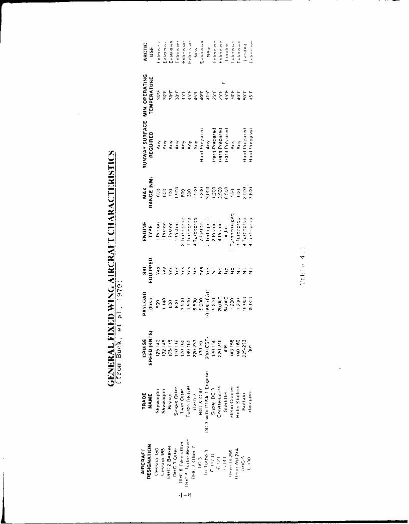
a U, L W W ~ U U -A
zw
cc-
4L t(( M m M
<fl < <>~ < . aC - < -a
cc ; ;;; -- 1
z T Im
zj z :
_n 2
4-j-
LE
V
' ft .C C
0J "2 L
> C CC <W'C CCI
U,,
40'C = :L
uj L)
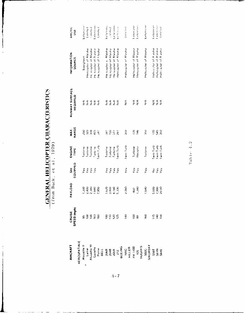
-3 ~ ' 7B '3 w3 '3v 7 7
CD'3B 10Z 'n 'D:n
4z X
LUJ
U
-,~ ~ E zz
Mzccx
~Zz fl ,Z;73333, 33333' 3
AW Z
LU- ~ . 4J~4,4 44,44, 1 ,4, 4~-~cc4
wO 333) 33 33 3~ 33
4-

The size of any entry hole will depend on several
factors including the size and shape of the ROV or AUV, and
launch and recovery techniques. Usually an entry hole will
require some routine chipping to remove new ice forming on
the surface and around the perimeter. A protective heated
cover (tent or hut) will normally be placed over the hole but
even this will not stop the formation of surface ice. Long
term projects should set up a system to keep the holes as ice
free as ossiLbie. Systems that have been used includ heat-
ing cables, lamps, ducts, and bubble generators.
The method of cutting the hole through the ice will
vary from one operation to another, the choice depending on
~r: f~ztcr_ i:cluding ice thickness and the availability
of equipment and energy.
Chipping an entrance hole by hand should be reserv-
ed for thin ice or if no other alternative is available.
This is not only time-consuming, but very fatiguing. Whether
chipping an entire hole or the final perimeter, care should
be taken to ensure that the breakthrough to the water is
delayed until the last moment; once the breakthrough occurs,
the hole quickly fills with water. Chippers are handy for
periodic cleariny of new ice formation from an entrance
hole.
A standard ice saw, such as used for years to cut
ice cakes commercially on freshwater rivers and lakes, can be
used if the surface temperature is not too low or the ice not
too thick. Entry holes are made by cutting the ice into
blocks after which they are broken free with a heavy-duty
4-8

chipper and removed with ice tongs. Care must be taken that
the cut of the ice is kept vertical and that the ice does not
freeze up again behind the blade. The teeth of the saw must
be set so as to produce a wide cut to reduce the chance of
such refreezing. Chain saws have also been used to cut large
ice holes in thick multi-year ice.
One of the most common methods currently used for
preparing an entrance hole through the ice is the powered ice
auger which can drill a hole through several feet of ice in
minutes. Bit sizes vary from small, 1 to 2 inches, to over 9
inches and with the use of extensions, they have drilled
through thick ice, even pressure ridges. The auger is norm-
ally used in combination with hand chippers and chain saws to
make large holes.
The thermal ice cutter uses warm water circulating
in a cutting tube in a controlled manner to cut a groove of
the desired shape. A delivery manifold of the desired"cookie cutter" shape delivers the water uniformly along the
manifold through a series of loosely spaced, small diameter,
downward directed orifices. Such a manifold is mounted
directly above the cutting manifold to pick up the mixed melt
and deliver the water for reheating at the heat source. When
penetration is completed, seawater floods the groove and the
core is left floating free. Holes of 28 inches can be cut at
5 feet per hour with a system delivering 80,000 Btu per hour
to the ice. Holes have been cut through 15-foot thick ice at
these rates. Multiple cuts can produce holes of large dimen-
sion; enough to accommodate most ROVs.
4-9
4.4 ROV Logistics Support in the Arctic
System logistics is probably the most important
factor in any arctic operation. Because arctic field inves-
tigations depend heavily on the logistics, careful planning
and organization are mandatory in transportinq an ROV system
to a work site and supporting it while in polar regions. The
success or failure of a mission can depend on the thorough-
uess that is devoted to logistics support planning.
It is extremely important that equipment be
prepared and tested for the arctic climate and weather prior
to deployment. Many items that have performed well in
laboratory engineering and user tests, including tests made
in cold chambers, have failed when used in polar regions.
General features of polar operations that affect
logistics support are:
1. Environmental factors, including blowing snow,low temperatures, and irregular terrain.
2. The general lack of facilities that can be usedfor support purposes.
3. The general lack of communications -- even nearpopulated areas.
4. The distances over which support must berendered.
5. Polar regions are sparsely populated and ameni-ties for every transportation mode is affectedby the lack of established roads, runways andother transportation support facilities.
The choice of a surface vehicle will depend on the
size, bulk, and weight of equipment to be moved and the type
4-10
of terrain to be negotiated. Vehicles that are commonly used
range from the small snowmobile to heavy duty specialized
tractors that may be equipped with wheels uL tracks. Speci-
fications of each should be considered when choosing the most
appropriate terrain vehicle.
1. Wheeled vehicles such as a crew cab truck, pro-vide an adequate and relatively inexpensivemeans of transportation when roads or clearedpaths across the ice are available. It is bestto use four-wheel drive vehicles.
2. Snowmobiles are excellent for local operationsas a personnel and small load carrier. Whencoupled with a small sled these venicles caneffectively support most local operations asthey are capable of operatina where larervehicles are not.
3. Tracked vehicles range in size from oversizedsnowmobiles with a cab to 16-ton vehicles thatcan pull a giant sled across the ic. LargerROV systems would require vehicles ofthisclass. In addition, these vehicles are usefuLfor supporting other facets of an ROV mission,e.g., clearina snow from a new site, towinglarge sleds of equipment, and assistinq in moy-ing and handling heavy equipment and sun-plies.
4.5 Launching/Recovery of ROVs and AUVs from Arctic
Pack Ice
Arctic deployments of ROVs and AUVs do not appear
to hold any major Qbctacles for small and medium sized
systems. Large systems would be hampered by the lack of
handling equipment. However, the ice does provide a strong
stable platform and we see no insurmountable logistics or
handling obstacles even for larger systems. The C130
4~1-1I
Hercules and even larger aircraft can land on refrozen leads.
The U.S. estabished an ice camp with as many as 40 individ-
uals, 30 buildings and over 500 tons of equipment during
AIDJEX.
Small ROVs can be deployed by hand from the ice
edge or through a suitable hole. Medium and heavy vehicles
can be ramp-launched and rccovered. Native Alaskans recover
whales using a block and tackle to hoist the dead animal onto
tne ice with the block anchored to an ice beam cut into the
ice. For heavy vehicles a launch and recovery frame with
electric motors may be more effective. The point is that ice
is very strong when col3, and can support large v-rtical
. a-s.
4I-12
5. SUMMARY AND RECOMMENDATIONS
This study included a review of the physical and
performance characteristics of the present world inventory of
remotely operated vehicles. During the last ten years sig-
nificant progress has been made in the design, development
and operational experience of commercial ROV systems. The
primary requirement for this technology has been the offshore
oil and gas industry. The present ROV industrial base has
been an outgrowth of developments by tne Navy. Within the
United States and Canada, as well as Japan and EuLope, there
are well-established manufacturing firms offering ROV systems
design and development services. ROV technology state-of-
the-aft systems have demonstrated commercial cost-effective-
ness and have successfully performed a broad range of F uinc-
t ions; many of the functions can be translated to mitsrv
application scenarios.
ROV technology exoerience in the Arctic has been
limited to field tests of autonomous underwater vehicles,
some trial visual investigations of icebergs u]sing tethered
free-swimming vehicles, and, at least one recent commercial
evaluazion of a low-cost tethered free-swimming vehicle
deployed from a Coast Guard ice-breaker.
From the ROV information data base developed for
this study an evaluation was made regarding the ROV technolo-
gy support potential to the AEAS ALi¢ Program. There is
ample evidence that significant benefits can be derived from
,military application of this technology to the key areas of
arctic site characterization, exercise support, and environ-
mental data collection.
5-1
,I

Performance characteristics determined to be avail-
able from this technology are:
* Three-dimensional mobility under the control ofan operator
* Under-ice operational limits are not set byweather
" One-time measurement support of temporal andtransient measurement support at selection loca-tion
" Long-term measurement support at one location
" Cost-effective for a variety of tasks
* Safety when accessing hazardous areas
• Platform for accommodating a variety of sensors,instruments, and tools
" Systems can be tailored for specific missions
* Covert
" Install data collection arrays
" Easy to transport and operate
" Candidate environmental data collection substi-tute for fleet submarines.
ROV technology research and development require-
ments do exist. An evaluation of anticipated military re-
quirements for site characterization, environmental data col-
lection, and exercise support reveal that technical solutions
are needed to overcome deficiences in:
o High energy, long endurance, on-board energysources for autonomous underwater vehicles.
5-2
" Quality and quantity of two-way through-watercommunications, both open and covert.
" On-board computer command and control utilizingartificial intelligence.
" Umbilical cables.
It is recommended that:
1. One small and one medium-size tethered free-swimming vehicle be instrumented and field eval-uated under the arctic ice canopy and in themarginal ice zone for site characterization,exercise support, and environmental data collec-tion.
2. One or more autonomous underwater vehicles beinstrumented and field evaluated under thearctic ice canopy and in the marginal ice zonefor site characterization, exercise support,environmental data collection and tacticaldevelopment.
3. An arctic ROV workshop should be convened inFY87 to establish requirements for ROV technolo-gy to support the AEAS program.
4. An ROV workshop should be convened in FY87 toestablish requirements for ROV technology tosupport all naval warfare areas.
5. A short course be developed and convened in FY87on the potential of ROV technology to supportU.S. Navy arctic and other military programs.
5-3


REFERENCES
Boretz, J.E. 1984. Unmanned Submersible Nuclear Propulsion
System. In: Remotely Operated Vehicles, Proceedings ofthe ROV '84 Conference. Marine Technology Society, San
Diego, pp 369-375.
Boretz, J.E. 1985. Tactical Remotely Piloted Submersibles.In: Remotely Operated Vehicles, Proceedings of the ROV
'85 Conference. Marine Technology Society, San Diego, pp
233-240.
Buck, B.M. 1968. Arctic Acoustic Transmission Loss andAmbient Noise. In: Arctic Drifting Stations. ArcticInstitute of North America. Washington, DC.
Buck et al, 1979. Arctic Flying. Polar Research Laboratory,Santa Barbara. 200 p.
Busby, R. 1986. Personal communication. Busby Associates.
Carnovale, S. 1986. Personal communication. Aquanautics,
Inc.
Coachman, L.K. and K. Aagaard, 1974. Physical Oceanography ofArctic and Subarctic Seas. In: Marine Geology and
Oceanography of the Arctic Seas. Springer-Verlag, New
York, pp 1-72.
Colony, R. and A.S. Thorndike, 1984. An Estimate of the MeanField of Sea Ice Motion. J. Geophys. Res., 69(C6),10623-10629.
CNO, 1984. Manual for Manned Submersibles: DesiGn, Opera-tion, Safety and Instrumentation.
Denner, W.W., D.R. Sides and M.W. Thompson, 1985. A Review ofArctic Environmental Data Bases. SAIC Final Report under
contract N62271-84-M-3728.
Dyer, I. 1984. "The Song of Sea Ice and Other Arctic OceanMelodies" In: Arctic Technology and Policy. McGraw Hill,New York. pp 11-37.
5-5
Francois, R.E. 1977. High Resolution Observations of Under-Ice Morphology. Applied Physics Laboratory, Universityof Washington, Seattle. Reoort No. APL-UW7712. 30 p.
Harlett, J. 1986. Personal communication. Applied PhysicsLaboratory.
Jenkins, W.T. 1974. A Guide to Polar Diving. Naval CoastalSystems Center, Panama City, FL.
Mayhut, G.A. and N. Untersteiner, 1971. Some Results from aTime Dependent Thermodynamic Model of Sea Ice. J.Geophys. Res., 76, pp 1550-1575.
Schwarz, J. and W. Weeks, 1977. Engineering Properties of SeaIce. J. Glaciol., 19(81). pp 499-530.
SCOR Working Group 58, 1979. The Arctic Ocean Heat Budget.Report 52 of the Scientific Committee on Ocean Research(SCOR), Geophysical Institute, University of Bergen,Bergen. 98 pp.
Smith, J.J. 1985. Battery Fundamentals: A Look Inside theContainer. In: Naval Research Reviews. Office of NavalResearch, Vol 37. pp 3-11.
Smith, D., T. Mellon, L.M. Sawyer, R. Yobs, 1986. A Feasi-bility Analysis of an Autonomous Underwater Vehicle forMapping the Arctic Seabed. Unpublished Report. NavalPostgraduate School. 26 p.
Thorndike, A.S. and R. Colony, 1982. Sea Ice Motion inResponse to Geostrophic Wind. J. Geophys. Res., 87(C8),5845-5852.
Weeks, W. 1980. Problems of the Seasonal Sea Ice Zone: AnOverview. Cold Regions Science and Technology. Vol 2.,pp 1-35.
Volker, R. 1985. Personal communication. ARCTEC Inc.
Wadhams, P. and R.J. Horne, 1978. Submarine Sonar Profilesfrom the Beaufort Sea. Report 78-1. Scott PolarInstitute. Cambridge, England, 65 p.
5-6
APPENDIX I
List of ROV's Including Operating Depth and Dry Weight
January 1986
A-I

coQ 0 >C
IN ~ 0 03~~
Z-~0 0r C14 m l 0%4340 4g V4) , 4.. Ul Pi 4
q6w4 V)0Zz z z ~ z 1 0 z
~~C>
r-C I TC 0I 0 C 3Co. C4 C0'4-< C> < < 0 C0 Lo 00 > 44
*'Tj ino 64mm zmmU)LO<>C m43 -oN U' 3
<>- 0NC0 3 r
0 U < Y%-0<
InJ
LU 0:
m C-
- Ui) C3 (DZ >4L CLL
03 0e .ZU 0 AZ-f
LL - IC',c
0 OC
0 Q Q aiiiD La

00C o g Co>cw Coy CoC00 0 >00 >tD0 QC >C
C>gCgg2Ogg C> <DgggWr .44 A m A <QQ
0fl 3%Q t 4 % (D - n r I ro' 3 a' Z w rzc0z 030CAN
0% tf - 0 y0%CDIT q3 y. MCflnU
C> C30 >C >0C >LO0 4<>0C
C>C . C $ C o2 0C : > C
00 0 40 n<r- a- ) 04% -: - 0 0<><>0t D( qa) 0C
'D -0 Z4 310L
(Dz~ ZI
>u1 U z nc at' -a
<j 2 z sj -~t~ S _ 0~J
CC L- .-S
I.- z 1-3 3
a a j a 0 a -,. G wm m w w w wata~: ak a x a a af aaaa aaaaooiu<uuu& Qu u u u u u u ouo
A A w Q La * & I 1 1 1 1 1 1 I I
888888888888888888888

W) %0 03 04( 04 0.Z004
W) ~ ~ ~ V M - mmC m!
zz
C> C> C
<: . N 0t 0) 0r 0 iC,)0NA N- ND 0. N0NC-)C
00 0
M3 bI C)Z Q o
I-
Oj 0) C
... Jm 0 IxI
ai z U, w w

m cn 0 mggD C(E) a: (% C 0( 0 ZZZZ<
(D~ 0 0 C>O 0 )4>7 > a) C62 o <o g u~ g g <: <44A m >00 >C) DU< <0
N. 0~C) 00 c0oo0 oo oo owo0o <%0% ~)C U0V<>OInOC 0 000C 0 0 0C
000n "0 o o-o0N0 ' O0 r-LO0 0z z
z i
U,
u 1 0I" . C M - rjLL
Zccz - LA La -! 2L g-I-A -J (a >o"' il -< USw)
(0K ZZ COl -C- U ci iL)OLa aco A , zS
Ix. orrJ)x W4 ma- X1 ZrW I'1 0rJ Ix0
a-J .4A - zL,.c aUI, ACC 6 nZ0(LAS -j> ><_ ! _ . CI Z n
>% S -J -11, -ix - Ci(I'o40M M4 :3,- L1 : L.L..
_ 0 ('4
2 ~ 0 u-rn t1~00 4 4Lei
r) w w 4-

a 00 D rwnowr- N olo{w 44AmOa4m4>4t4UO % m4O O4 40 mm o
.#O 1000%u U3~"
Ut-u-N OO< cflO 030m<om-7 0 co0oo
_ r - r- at P V04 V)04 -- 04
'o0 0 <> c> o O)0tO0 ~ ~ ~ ~ 04t C4' <> <> -t0 C'C0DC4- > >C> 004
00 --- 0 lnf 0-t -0 t'OO
:r
-J 0-
M, Li M , ,= i x :3
4~~L -I CZ G*~~~ aw a w0.
wsVI Naa cor>a-NMq n0NC a w n0N0C

c>C>C>C C < C4 <DC>ITCC31(-z0
C> 0 0 0 c> > 0Ot'T <5 c><:> 0> <00000 >
-' 0 &0 r
00
00.
- U)- ma00N00000U 0k r 0U- Z0c- -in a. N -U nou)v noc46P Nu) L ) cl
(004 ~ g C- U) 0 U Q
4E ij C) A
a. w (p IV I-- 1- 0 8 4 Z )Z
-J 2...ow lu- e-'.LLA -
oL ofOO 0 CEW (1 a-LLI z z -C
- -W- -w- --cc- - - D - -U- -
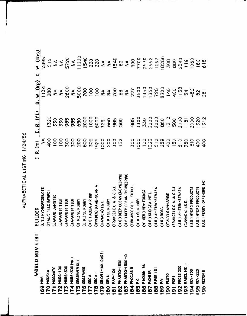
Ln 0 0 0 C >0 a) <
0 C) _ C o :)C D :
0 00 g<<g < 6 _C 40 >0r r qC 3I l :jE ZM Z- ' 4<0<mm000 l-0 mU)in C040Z rLO ~Z uiz r-nonC te a)
CD, C>CCC5 C> a:
fn0C >< < >a)Ar U)& 'C63 < ~ g ~ w 4 Cg<oggoe6C> ><C (Nooc' M
a OZ4Dmar inO m 0 4 GU' e n K Uo- U3
aD
I--(I)
a i
M L
EGi - 000-
ow,- - ra .,. . - U4 0 O a- CL .
UU.
oZ Z Z Z (0 (w w z a c ~ arry44 ? O 4 r~ Y. *j le <r 0i
w w < C w a4fl l f f 0) 0 D it D f it fl > .l M fl (..)f
In i
ol t - 0 a
a. 9L le e a. Ca m-tI
0 o mcmm

0401
0 C> e) V 0 <>0 U)0r
4n U-) (1 i :
(000 CE)- 0 C0 00oo DooOoooo0
- IN---------C 03 W) o fIle
OD
1. 00~-0000O0- 0C>C -0U~O10~C'4 Eonnr~sncn~ 0- -G~c r- P) v)nn o ns
-
CD
U)ri-iY
<J
ta 0 -
mf 0 0 0 0 LA C 4 I--** L
co W a co'~ nCt >> ~ O
CCJ La D~~C~ I -m n0 0 0~.- CnZ 8 lw i" r\ r4 r
0u~f m 0)w ~ u "
o - 0
0 0-ix a .6 0JLIx LAS z;0_ A
a0 > Ne 000 0 IL
xz z tj(( L 4
wO O O O C O Oww w w w wC

M ~ ooooo~
U-)
o g 0 RD" , (_l -t-- < >U)0 n < > - >C , &<>I >p
1-I e 0I T >0 'a )r
c0('0C>000 0q1000< .0C 0 < 5M0 C> 0 - () 0 4C>0<C : 5a)5 U omqC ' : tI r
0 D6 : ( 3C>a)z0Qz r n04C n0C 0 C
-Q. 0 JumwLa
W z 0
at0
§w o l- OUJ CD0W.- w -
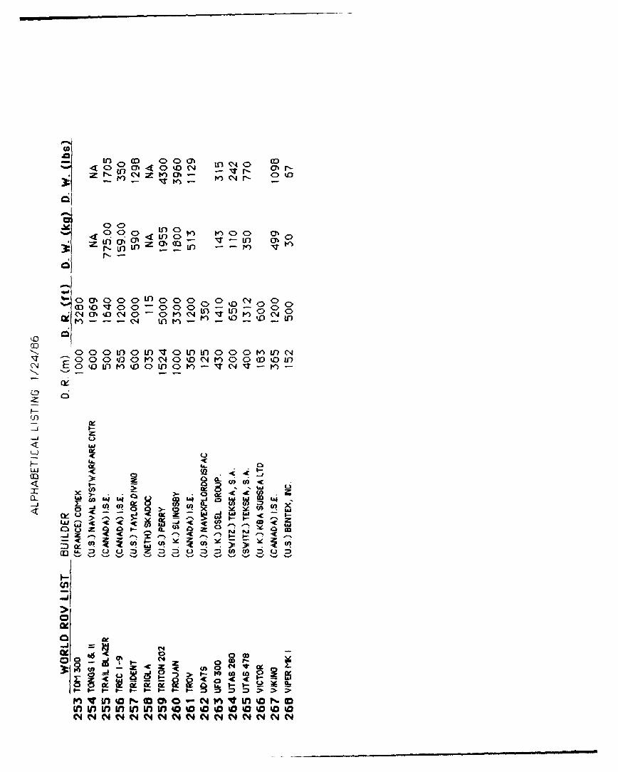
(A(N
:2 I0 G3 C> 0 m tn CD1%. C> 0 C % l
in- r,-o S4 I ) -
I-
I-
tn -' - n '
LO C)
4L
a-
04($ LW0qU
(.4A'r 0L 00J> -% , 1 1 1 - -
LZI - " 5 -j C C3 o

APPENDIX 2
DIRECTORY OF ACTIVE ROV USERS
A-2

DtFRECT0RY ,g. ;.'-. , FEFT
DrectoruAmet ek, fr a
790 Greenrielui Dr.F C Box 666El Cajon, CA 92022(619) 442 3451
2 Anc hor S ysems AmTour Super Montparnas-,e9, Rue :eorqes itard75015 Paris, France:1. 533 71 11
3 Aqua-Air Industr1e, inr:' 0 Drawer 7 19
!ak 'rivyekHir, LA 70050, 504) 362 8 124
4 0 n q n e s
N cl 5 ',-yo r0 Traoe C enter
Ned ,OP: r 1 f1004;-
t,2 121 393 536b
5 Oatele Columbus Laboratories515 k I AvenueColumbus, OH 432010614) 424 6424
6 Eenthusj n:Elierton DriveN Fa&mouth, MA 02 55C(617) 536 5917
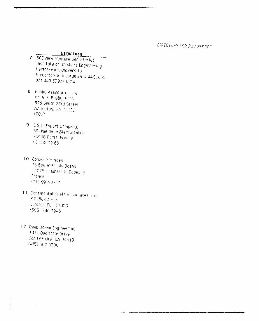
Dre c t ru7 SOCJL Ne-Y /enue eeti~r at?rtfstltclte Of Uiifhre Enqineenp-rHernot-watt LindlversitqRicmdttcln Edintqurp-i EH14 4A---Lf031 449 7-97'.7374
Mr., R. F ~suF576 'Sooth Z~' ' Sttr HPt
7 r
9 C S~I(Ex<ort L Orr-1pflIj,
7, la ee e C"
Ju0 !rn; ter-,FL77 _351 ",46~ar '704F a
14375 DOI t' Iei Ic v e>
An 746oro 79 46 1
~415 562 q ri
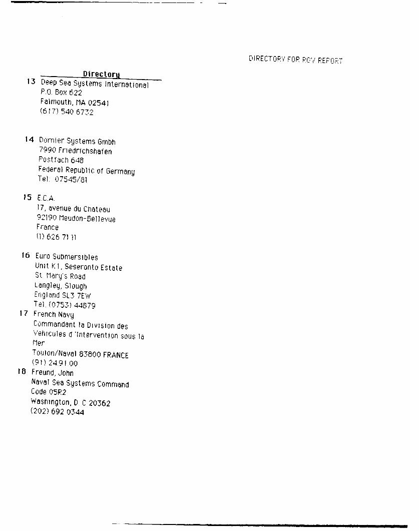
DIRECTORY FOPPR. PEFORT
Dirpctnria13 Deep Sea SQStems International
P.O. Box 622Falmouth, MA 02541(e, 17) 540 6-772
14 Dormer Sqstems Glmbh_7990 FriedrichshafenPostfach 648Federal Republic, of GermanyTel; 07545/61
15 E.C.A.I17, avenue du CIhateau92190 Me udon-SellevueFranceMi 626 7 -1 11
16 Euro "SubmersiblesUnit K 1, Seseronto EstateSt rMarg's RoadLangleq, SloughEngland SL3 7EWTel. f0753) 44679
1 7 French NavyCOmmandant ]a Division desV"ehic uIe s d 'Intervention sou,; ]aPierToulon/Naval 83800 FRANCE( 91) 24.91.00
18 Freund,.JohnNaval Sea Systems CommandCode 05R2Washington, D. C 20362(202) 692 0344
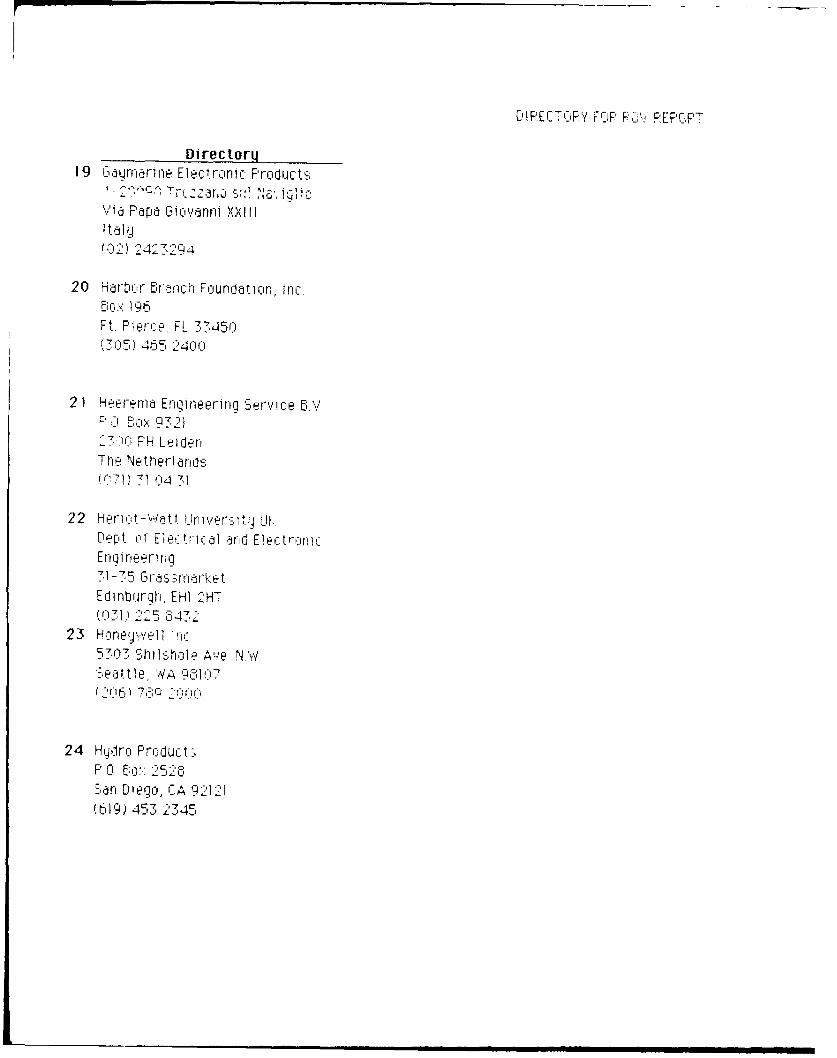
'IREC70P'Fi FOP PLR EP(OPT
Directorg19 &g~Lrnri~1ne Electlironi c Products
Wa Papa GTovarmi XXI It1 tlL
(02) 2423294
20 H drl)o:r- Br~nch Foundati on, Inc.
Ft~ Plaer', FL 33450(3015) 465 2400
2 1 Heema-n Engineering S-ervice 5A.,P' CBo 932127K00 PH LeidenThe NetherlandsIr0i 7 1 1 4 31
22 Herict--wa'tt Urniersi tg LIKDept of Electric al arnd Elec:trciniEnoineen ng
Edinburgh, EHI 2HT(031) 225 OR43
23 HonefJa.'11 m:5303 ---itwsrholeie N Wi
24 Hgdri: Pro:duct-,PC, Bo 52505,San Dipego, CA 9212)(419) 453 2345
i fPE C CP' FOP PC''PPp
25 77 : Irectorm ---25 IFEMEP fi:'rrrw~tr1, CNEX~,o6J6 A Venu J- l, a ij a7 01h- PdtriS
26 Institute, nf Lc:&c)ooq,C*a 11 &t" q Cf fCInC e U-'
27 Interratfltita Submarinep
261)1 turr i -,tt-et
:50Aerc, C Our-t~'3 fleq C. 9212-7~
(6j?9) 6 i0
29 -1- 'dt f1r~ne Se f"C nTprrino? Jy ':-.enterDC&eP'-e Tech~noicQg Clepartt-nernt-5N,3tSusrnrlma-c.jo
"u~dCi tg, I~r 27Y-'
30 K'ae~ef-r-rer Eriqineerig /F 0 Box~ 22.2 NO 2l '4~N c r g'172 5:55
E-IPECTOR*{ F';K' F'EFC;2T
Directorq
31 KBA utsea LtdUnit 7, Lister Roadb yngsutroke PG22 4NPUnited Kingdom(025b)- 52740/9 & 546392
-32 Klein Assoclates, IncKlein Drive
ler, NH 030790603) 893 6 13 I
33 KftI Oefl S e stans11667 West 90th TerraceOverlanj park,, S j6614(913) 694 90'22
34 Land and Mianne Engineering LtdFort Causeway, Eromt0oro-lghWn-arf erSeysi Je L62 F'TG
35 Lockheed Advanced Marine Systems3929 Calle fWOrtWnidSan Dego, CA '92123(619) 569 8540
36 Plarne Fhys Cal LaatnrqLIniversity ot California3.5n Diego, CA 92152(619, 452 254
37 ~ Direct ory -37 ra3'Bchu~tt: rst~ut~of
C'irittridge, Ii TQ
H~ncli-i u Hi'4j51
39 ui Wi ninprian bou
Tok go ()J, Ja5p anr
40 " t cSUI CC.edfl ee;cp en nEn'i n~ernQCc, OLt MCDECl
T 4Ci10~Japan
414
1 4 Nor"..ai47 9 7 h(I61f1
4 2 Nj inij! e ~~ e~E tst,,-ipnl (FOA)
J4 S02 t4 ockflcr Swede
[M'GM F'CJ-' FOF R,. VEFIT,
Directorg43 Clu i-oastai Systerns Center
CIot~ .ity, FL
44 Naval Fa lities EngineeringCommiCi~vil Engineering Ltratorr- can E ngi nee ring DeptPort Hueneme CA 93047.8 05) 982 5420
45 "' O,,, cen ? sem Ce-enterCode 5'2:an Diego CA 92152
46 .. rMnoraphc CfficeNSTL 'n-nbay St Lous r1S 3952
6501) 0859 45243
47 ,',val Oidran e Di :-,a:. lTech'nology Center
In1lan Heatd, MD 2064111U) 743 4530
453 Naval Fesearch LabortoryCode 5823',vasrnqton, D C '0-75202) 767 2695
U. RECTOR'! %F P< CFF
Directoru49 Naval 3' 'sters 'W-art are r c-,rjtpr
F t Lano u 13,e, F L 3315
50 Naval Tom-e®d Stationf-
(206F1) 32 6 .2511
5 1 CII fshoire Sgsternis En:1 neeri niLirnited ('JS-EL Group)Eiountflr4 RoadHarfreus- Indus,-trial EstateGreat YrotNorfolk NR371 CiLU
Riverad 5eacfii, FL 33-I44*7~9 C4' 1 F
53 rr I I
Olhta-k u 7 cl qi':', Japanl
54 Remnote Ocean cj4st emi-s, Inc5111 Sanlta Fe St SteLSlan DiHeqc, CA 92109
(19 ) 46831 3 2

55 ~A'F~ c, -c~ E,
Eiger.stflj, Nonerwji
56 PJO.~. rIternat jnniJ
n1r ae ecn cr', f.- A ~ r ~J
5 TJc: C -~r1er'1tyCener 'i SU
d Fo u 0 r e. 3 I e
59 n q~~ Fn p r ilr L t
rn I r lat1:
Ft &~r~rjHClldnd
wDr-:P.;v7 CDP PEP R PT
Directory ..........
bi Scrilt FCA
17 Av.,enue 'in Chdtetu~92190 IleudoriMewu, France
62 icn'lecn Kd0 0 E~c'te1 Ic' PcvjiiMe'1ta, CA 93017
1505) 9b7 0437
63 3;eerru llanue Sys4temsLj efIe I i:5 arnid tl a r :u Av en u E
p516,* 5 74 1113
G4 'Suflrrie De.'l~etGrouo Fne
San lo1ego4 A2 Qf M
65 3.'Jv~rtrrr HeAY' ndkJ3?r92 LKJNew-terac h 51d' 2-1
Ginaku Totg IY
66 o te' 5261L, W,,oodladc Drive, N W'washington, 1). C 2008l(>2). 6 .:* 000
L E T CPE Pr 0r EF'flF
Directnrii67 TFi cr Dlyn vi NO SidI vge no.
EBOX 795
bielle Chd~Se, LA 70037504) 3.94 600()
6B Teoroare Sp A
69 An, LA,De timei0r e Rco
5r iog D riot ,E Est,5teMuee, A82 5JYw
70 Linder.-vat r flarine .>EQiu~ipent
1Fairnritircuqn RonaFarnorour~Lqn, Hi rn'shnre Ciij)4 tI5A
TO Owntoruwgh (HwAns-495J4
71 Ur ,,er iti4 of New d--Q-lrM1arine Sgserns Erngineeringq LabDuirrr NH 03624HT 749 NO
72 iinn'rCF g o4f Was.hirhl -AppI ia Phiic s Lat'crator

Directorm73 1 lek Lt (I
ant 10f. t t Itt 1dus -t j s F rla Prefhe~d; errace, Ur)g
~Lren ~i IG
74 Wyestingnotije Electr- COr-M-at on
Cl. , ,14 ID 40
I - 'I ai El 1 4i
76 HoI e - jo rapnic nt-J-111 H-rh I 2 4;

APPENDIX 3
ROV MANUFACTURERS AND OPERATORS
Reprinted from 1985 ROV Review
Pages 11-27, 31-42
(with permission of Subnotes, Windate Enterprises, Inc.)
A-:3

ROV MANUFACTURERS1. Manufacturer 2. ROV Name .':. Primarv Task 4. Rated Depth ,5. Propulsion & HP '6. Deployment Cage Standiard Sensor,8Manipulators; 9. Payload, 10. Vehicle Dimensions, 11. Weight 12. Total BuiltUnder Build I131. Base Price/ Avg. Sale Price, 14. Comments
I. AMETEK, Straza Division 2. GEMINI 1oo 7. Color TV. SIT b&wTV. sonar i,0r791)Genil rv 1 e ok ut-ups cage), stills camera, thickness probe.
P.O. Box 666. El C'ajon. (CA 921022 UP prober mTel: (6191 442-345L TFix: 288951 4. 125A) mn 4.000 ftu--standard. Depth 8& One ;i-function master/.slave
rating up to 3)00) m i 10,000 ft) One 7-function rate controlled-- optional Two 4-function rate controlled
51. Seven 15 hp hydraulic thrusters: Two 2-function rate ctintrolled100) hp standard. 9 67.5 kg (150) lbs.)
6. Tether management systemn standarcL 10. 2.5 m 198") long. 1.44 m.i.
7. CTFMl sonar w/scan conversion, wie 1 0)hg
auto depthi heading/ altitude, stan- 1I1. 181 kg (4.001h bs 18.144 k,,dlard interfaces provided. 140.1000 Ibs) - vehicle. gurage.
8. Optional---any type. winch & launcher
.ASD');209. 22.7, i50) Ibs) standard. :360 kg- . (
.Inspect ion. NDi' & light work 'd-rill (8))) lbs) with additional buoyancy. llrig sui~port can be perfoirmed w-ith Vertical lift approx. 675 kg 11.50))available cable i-ttter & manipulator lb,) plus payload. 14, High pressure erosion cavitation
4 I' rn,;iO))) I 10271. i-n 17) ong 188 m system-- to bright metal'i, 1 OM I 1 72 wide.m 17) m ng 5182. chmh 2 and 4-tunction manilbulators have
x .Se\ ci hydraulic thrusters. 21) hp incrwease 427 cm 152) or moreit suction C-ups to secure ROV it trto,qaIndarci -higher power pack, op- atdditiont of work mnodule.) ir hncenntional) High pressure ptump on garage c,
11. 204.5 kg 14.50 lbs),' 1)) tons nected to vehicle througzh hose in6. Full cage or top interface manage- i-enter of neutral tether.
ment systemnf MSI. TNMS provides 12. 1 11ilslet trials to begin Mlarch 198.51 ____________ ____
tor dead vehicle recovery. iperational by mid-.sutnmer)1. A.METEK, Straza Division
7Interfaces for still, camera, TV ianyv 12. ;,75,1000 ) approx) 790 Greenfield lDritetype). I TFM or plesonar. C P P.O. Box 61;6. El Caion. CA 1;202
pritb. af catera ulse14. Work miodule can lie factory con- ---
prbe at amrafigured to order or bv user with Tel: (619) 4-1'1-'1451 'ix: 2.589.5 1
Opt ional 5- funct ion rate cotntrotlled drawings supplied by AMETE K.in d i-I'Lunet iiit grabber. ____________
.4.0kg~l bsi I. AMETEK. Straza Division790 G reetnfield [rive
!ist' ci 72-i ;og. -n -m 00P 1)0. Box 6611i. El Cajon, CA 92022wAide. 7"n ct '2 ' high Tel1: 0i19) 4 4 2-:1 5 1 T~x: 2 88 9571
t! 474 kg iI,1IMl Ihl) M kg, i ,S21 lbsI
2 2 . 11' s%%ten in service %larch
ing. depth. altitude Si CO RP1)
AMETEK. Straza D~ivision 1IsptB)h
P' 0 Box 66;6, El (ajiin. CA 92)02211.1 if19) 412:13151 lx; 288951 5_________ i Six hvdraulii thrusters: 0h
-6 Standard
H&\V l..I.I.I' in pian tilt MIatnoptions1
2. ~ ~ ~ 8 PRF 0 l -functiitn rate controlled optional:3. Inspection, cleaning, N[)T 9 2:4k 5 ,)l
6. Stand~urd I I vo11 kg 950 lbs 86:) kg i 1.9))) Ibsi
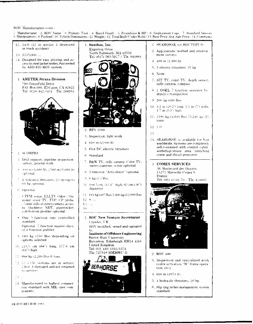
ROV Manufacturers (con.,
I Mlanufacturer 2. ROV Name :3. PrimarY Task ,4. Rated D)epth /5. Propulsion & HP /6. DeploYment (Cage 7. Standard SensorsS. Manipulators, 9. PaYload, 1i. Vehicle Dimensions, 11I Weight / 12. Total Built/Under Build /131. Base Price,, Avg. Sale price ./14. Comment
12 . 14/0) 112 in service: I destroyed I . Benthos, Inc. 2. SEAHORSE iex BOCTOPI'Slin truck accident) Edgerton Drv :38. Applications testhed and environ-
... esypiotn North Falmnouth, MIA 0255i6 ment survevsTel: (17 56351 Tix: 940884
14. [)esigned fo es- iotn and ac- 4 4001 m (1.3l00) ft)cess to steel jacket nodes. Succeededby ASD/620I ROV sYstem. 55 electric thrusters: :15 hp
63. None
1. AMETEK.Straza Division T7. S IT TV. color TV. depth sensor.79) Greenfield IDrive stills camera, campassP.O. Box 666. El Cajon. CA 920)22Tel: 6191 442-:,451 Tlx: 289,51 8. 1 OSEL 7-function seawater hy-
draulics Manipulator
9, 200) kg 14411 is)
1)). 8i.2 m 11.1long. 2.1 to I-') widv.
1.7 to isiS' high
1I. 118o) kg 2,Go11)lbs 15241 k,- 15
12. il2. RPV-200))
18)1Inspection, light work
14. S-EAHORSE i, av ailable for hire1. 6o m 2.00 ft)worldwide. Svstems are completely
5. Fve C eectrc trusersself-contained with control cabinS.FieCOReecriPhrstr workshop/ stores area, launTching'Si))ii) . Standard crane and diesel generator.
Drill support, pipeline itnspectiotn, - & V tlscmr.ClrI .CMXSRIE-orycy. 4eneral wvork RWT.ifcrea io %. ICMXSRIEstereo cameras, sonar optional 3.BueaddsOenwi ii I f8111 t : I -iil ii I .11111 I t i d.B uead esO an.'ptional S 8- tutiction "Articulator- optional 1:3275 Marseille ('edex 9
FranceJ bvdraulic thrii,ters,. 2, lhp utp to) 6 kg, il I b1)s) Tel: (91) 4 1-0 1-i T~x: 4119O5iio hp o)ptional 10,1 -)~ (it (48.4"1 high. 95 coi G88')
I ''FM 'na. ILI.\' ~w.)) 1 1. 158 kgz t-107 Ihs), 5. 400i kgi t2-000) lbs) *
ilinal: color TV. TVP' 1 P probe. 26
:5 to m tills -r stereo camera. acoos-1.Tic thickness NDT. pipetracker. !4.ub-bottom profiler optional .____________________
O~ne 5-function rate controlled I BOC' New Venture Secretariat,tandard I rawlev. 1'KOptional: - lunction master, ,lav. RO V modified. ,%ved and operatedfr 4' bincti00 gra bber liv:
Institute of Offshore Engineering9. 11) g :1n Ihs) eped to 00Heriot-Watt I nit'ersitv
options selected Riccarton. Edinburgh' EH1 4 4AS
10i 228 .5_ cm (88") long, 177.8 cm I nited Kingdom61'') high Tel: 11311 449 33:931/33:74
Tix: 727918 IOEHWI' G . ROV 409)
i i~8 k Ihs/6 ons:1, Inspection and specialized work2 i i,: ; s s-terns are- in service: (valve activation. 'H- frame opera-
2 lo~t: I datmaged and not returned SRH R Etubn. eli-i
I \1nufcturd t higestcomrer-5. 4 hydraulic thrusters: 211 hp
tl tndttrd with IL I pec comn A. Slip ring tether tinanagenient systenip itten Is. stand (ard
I2 z it 1 RE .IF W, li.0;
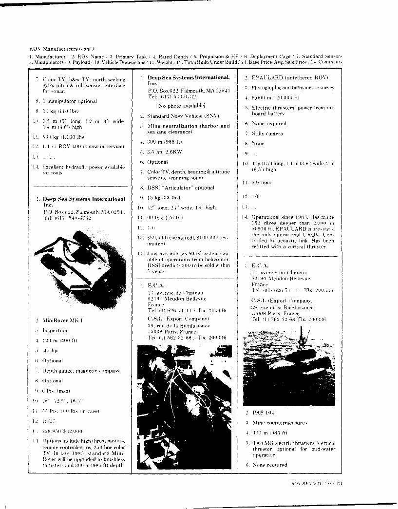
ROV Manufacturers (cont.)
IManufacturer 2. ROV Name . 3. Primarv Task / 4. Rated Depth /15. Propulsion & HP / 6. D~eployment (Cage 1 7. Standard Senlor,S. Manipulators./ 9. Payload / 10. Vehicle Dimensions/ 11. Weight, 12. Total Built/Under Build/ 13. Base Price/ Avg. Sale Price/ 14. Comment,
7Color TV. b&w TV. north-seeking 1. Deep Sea Systems International, 2. EPAULARD iuntethered ROV)gyro, pitch & roll sensor, interface 3.Poorahcadbahc.trcsrefor sonar. P.O. Box 622, Falmouth, MA 02541 * htgahcadhtvercsre
I manipulator optional Tel: (617) 540-6,3:2 4. 6,000 m. (20.000 ft)
9. 0 g 10 bsNo photo availablel 5. Electric thrusters, power tram on.9..) g( b)2. Standard Navy Vehicle iSN hoard batterv
10). 1.5 m 5') long, 1.2 m W4) wide. 6. oerqie1.4 m 14.6') high :3. Mine neutralization (harbor and .Noerqid
11 0 g(.0 b)sea lane clearance) 7.Stills camera
12. 1l'11 1 ROV 40)) is now in service) 4 30m(8 t Nn
5. :3.5 hp: 2.6KW 4.
1.Eclethdalcpwraalbe 6. Optional 10). 4 m (I:T) long. 1. 1 m (3.6) wide. 2 m
for tools 7.Color TV, depth, heading& altitude (.)hgsensors, scanning sonar
11. 2.9 tons8. DSSI "Articulator" optional
1. Deep Sea Svstems International 9). 1-1 kg (33; Ibs) 12. 1/0Inc. 10(. 12 long. 24" wide. IA- high 13.P,.O. Bo x 622 F Im ou th. M A 02 4 1Tel: 1617 1 _14l)-67325 11. 90 Ills: I15 1b) 14. Operational since 198:3. Has made
150 dives deeper than 2,1m) m12. 1) (6,600 ft). EPAULARD is presentv
1:) .)O~w (stiiatdl! L0,00 (et- the only operational t'ROV' Coll-a etiate)!101.0))l1et~ trolled by acoustic link. Has been
matd)refitted with a vertical thruste r
14. Lo~w cos-t mnilitar ROV vystem cap- _______________________
- able of operations from helicopter.
D851 predicts :30 to he sold withbin I. E. C. A.Years. 17. avenue du Chateau
921 90 Meudon- BelIlevue
1. E. C. A. F'rance
L7, avenue du Chateau Telt: ,11 6tG2 6 71 11 Tlx: 2 0 k12
92 191) Meudon- Bellevue C.S.I. (Export I ompanvFrance :19 rue de la Bienfai,,anceTel1: f(1) 6 26 7 1 11 / TDx: 2):1670083ais3rac
2 MiniRover MK I C.S. I. iExport (ompanv) Tel1: ( 1) 56 2 :12 68 Tlx: 2mri:1639, u el Bienfaisan -e
31. inspection 7.08Pars France
4. 12)) m 140)0 ft) 68Tx 1 _
.5 h p
6, Optional
D.Iepth 4zauge. magnetic compass
Optional
9I G lb5 (max)
Pi 2N-. 12 5). Is .
1 1 -5 lbs. I)1l), (in case) 2 P P 1)
9/(2", 3. Mine countermeasures
I :~25$5)$32)))))4. :100) m 9!85 ft)
I I O)ptions tnivlude high thrust moto)rs. .. Two.MG electric thrusters. Verticalremo)te co ntrolled in s, :15)) line color thruster optional for mid-waterTV In late 19N5. standard Mini, operation.Rover will be upgraded to brushlesstbnprter and:ij :10 1985 ft) depth. 6i. None required
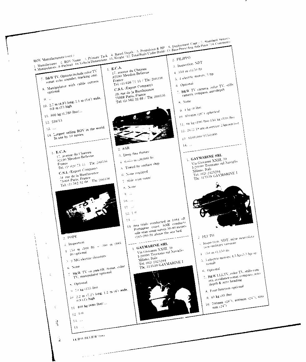
da A
' ' ae qa 4 om e
ho Rated DO)
cuttersV (Am
9
1moed ni
. 0 % % a f l urP ' , cab eelv' ) Ow
oNS 1o
\'eF'jPOien lit pafl)
%1,9fct. l'n'eoa deI n a sn e
r \ i
tm e ion,Man 1ulato" eat
CN. opton k)Nledol( ellvu
moors, b
ec .su d r rcFrance
j" e'le
4
l
5.lip all) rt . 4irace'
\olo r~O n tilt
39efa~I~
1 9e
1)rFrnce
mpas
Wide.. -'ko ar'-Tx
1 ) k9~'~ (I- Ih' ihe >
SARl
_C A n d i ('h t I o " e
\lel- Ilc- I ~tr _f \N I b,; -suicTrezzaric
T\ aluatnr optirINV
q~~~~~et ru&el 'na r'I
rt, /l"1 0 ga1 s r c )sansOl
12 1/
13. of
1.in
I;I
in AY STntl

ROV Manufacturers (cont.)
1. M\anufacturer .2. ROV Namie 31. Primar ' 'ra,,k 4. Rated Depth 5. P~ropulsion & HP (i. Deploviment Cage 7. Standardi Sn-r-SManipulators, 9. PaYload Wi Vehicle Dimensions II1. Weighti 12. Total Built, Under Build 1:i. Base PricelA%-. Sale Price 14 ('ommtew -
11. 1601 kg :152) bhs.';120 kg (704 Ibsi 1. Hv~dro Products, Inc. 1. Hvdro Products, Inc.P-O. Box 2528 P.O. Box 2.528
12. 5,12 11777 Sorrento) Vallev Road 11777 Sorrento Vallev RoadSan Diego. CA 92112 USA San Diego, CA 92112 USA
12 . 52 ..0,000 I commercial); S300,000) Tel: 0319) 453i'-2345 Tel: 619) 453-23,45militar'l,'$S280,000 1commercial). Twx: 910 122 11*1 Twx: 910-:122-1 1.1:t
S :15.000 ( niil itarv)
14. Power bv internal batteries or viatether cahle. High resolution sonar
1. Harbor Branch FoundationRR 1. Box 196Old Dixie Hwy 2. RC.225Ft. Pierce. FL .M:450) InpctoTel: 1(505 465-24001
4. 1.51 ft.
54 electrical i: hpi thrusters
6- . Standard
7.Depth. tether payout, LI.Ll'
8. Multi-function tool arm optiolal-. 19. N, A
2. CV- f151 10). 20" high. 26" wide, 201" diameter
2Inspection & limtited access work 1.1))ls:745b.
12. 98 1 includes spare vehicles onl%)1.6101 in (2.000) fti 5 are in service, 2o1 vehicles hav e
2.UORD 11 (Cabled Observation & been known lost or destroYed)Rescue DevicelI. I hydraulic t brosiers 13) $ 1 59.510(11vehicle only) 5410 I Ot'
.1Observation, inspection f; fndard 14. Also features auto depth, head ing.
4 m11 in(30M i pitching optics, screen annotation.I T tether management -strobe flasher
4 ~dauicthuser: .7hppan' tilt T%\. altimeter. pitch roll Opton itnclude pitching color TV'.5. hdrali truser: 1.7hpanglemnagnetic & inertial heading. fi telemetr\. imiage mreasuring s%*,-
6 Not used turns count er. depth sensor- tem. ecmergenc,\ locator tether t iter. keyboard annotation anil muit
7 WL.LI.'1\ on pan/ Iilt. cominass, 1 -axis single Manipulator function tool arm.sile s;can sonar, depth sensor.
I1mm stills- camera t 1) I lb5
()Inu 6 funct itt I International Submarine
I k 0 bs ~I IS' high x _2- wide x 5''long Engineering Ltd. (ISE)26011 Murray St.
11) 1__ cin 'tO 5) long, 1109 c'm .1:i) 1 1 1,2001 Ibs: 29114)) lbs. Port Mloidy, B..,Ceadla %":,H IXIwide. 121 4 mn (Is")' high Tel1: (60)4) 9 ;) 7 :,42 1
Tlx' 04-:153t554I-.- k_, I 1.11m) Ihs 12. 11?/01;8 in service!.) lost)
1 3 $ 199. 000l vehicle onl Y)/7 .50Oml
l14 1,'an be l'itticd with auto depthihead'I .~'cmy 11.T2 riftilical aIllows for ing. pinger strobe, icable cutter.o)peration in 31 kt. surface ciirrent sonar, diagnostics annotaition.C ORD) 111 being refurbished for Photsea stills camera. dual manip-41immer I18.7 operatlions in Lake ulator, color TV and auxiliary chan- 2, AM' S Iiitonomnous RemotelySuple rt r ne Is for controls & sensors. Opemirated So bm ers 1)11')
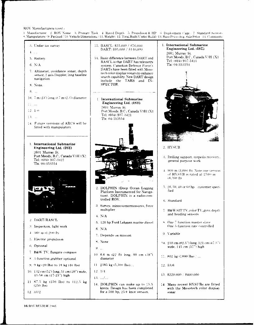
ROV Manufacturers (cont.)I Manufacturer 2. ROV Name 3. Primar. 1Task 41. Rated [Depth 5. Propulsion & HP 6. Ieplo -vment ( age 7. Standard Steosor,{ Manipulators, 9. Payload 10. Vehicle Dimensions; 11. Weight/ 12. Total Built/Under Build,, 13. Base Price/Avg. Sale Price ,14. Comments
3-. Under ice survey 13. RASCL: $55,001)/ $70,000 1. International SubmarineDART: $95,000 ,' S146,000 Engineering Ltd. (ISE)
4 .. 2601 Mlurray St.
5. Batterv 14. Basic difference between DART and Port Moody, B.C.. Canada V3H IXl1RASCL is that DART has telemetrv Tel: ;604) 9:37-:3421
6. N/A system. Canadian Defence Force's TIx: 04-:35:3554
7. Atimeeravoiancesonr. dpth DARTs have been fitted with Meso-7. Atimeeravoiancesonr, dpth tech color display sonars to enhance
sensor. 2 axis Doppler, long baseline sac aaiiy e ATdsg
navigtioninclude the TARS and IN-
S. None. SPECTOR.
9.
10. 7m (2:1) long. 0.7 rn (22 )) dianmeter I International Submarine
Ii Engineering Ltd. (ISE)26011 Murray St.
12 1 It Port Moody. B.C., Canada V3I lXITel: (604) 9:37-:3421
1.)...~TIx: 04-353554
14. Future %ersions of ARCS will befitted with manipulators.
1. International SubmarineEngineering Ltd. (ISE) 2. H YS['126011 Murray St.Port Moody. B.C.. Canada V'.3 H I X 1 1. Drilling support. torpedo recover,..Tel: f6041 9-37-:3421 gnrlproewrTIx: 0 4-353,55 4 gnrlproe r
.1. 140 m (3,000) ft). Note one versionof' HYSYB is rated at 257001 to
2. DOLPHIN (Deep Ocean Logging 5 (.:(,4 r0)h utmrsetPlatform Instrumented for Naviga- fledtion). DOLPHIN is a radjo-cort.trolled ROV. 6. Standard
:3. Survey, minecountermeasures. forcemultiplier 7B&%VSIT TV. color TV. gyro, depth
4. N/A and heading sensors
2 AR/RSC . 12(0 hp Ford Lehman marine diesel s. One 7-function master slave:1 Inspection, light work 6.N/ ne 5-function rate controlled
4. 16);) m 11.20)) ftj .V ra lDepends )ii mission9.Vral
5. Electric propulsion N oneC 10. 2 1)1cm 192.51) long. 12 1 cm 147.5)"i0. Optional wide. 145 cm (57") high
7 B&W TV. fluxgate compass 10, 6.6 mn 122 ft) long. 99 cm (09-1 11. 902 kg I 1800 lbsl2S -function grabber optional diameter
9. 94 kg (20) lbs) toi 18 kg (4(0 Ibs I I. 2:185 kg (5,300) lbs)/.. 12. 52/6
10(. 132m (i152)1 long, 51 cm 120-) wide. 12. 1 /443.58 cm-i 11-3)hg 13 :. $220A00 ' $4040o0
I 75k 17-2:1) hig 1:12.5.kg
(2675k (s)) 1b4. to125DgIOLPHIN can make up to 15.5 14. Many recent HYSI'Bs are fitted
knots. Design has been completed with the Mesotech color displaY12. :1:/2 for a 500( hp. 25 + knot versiotn. sonar
I61RflVbthr5s
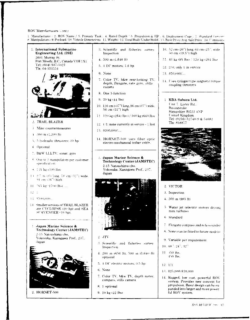
ROV Man, ifact turers ', ant)
1. Manufacturer .2. ROV Name /' :3. Prima-v Task .,4. Rated Depth '5. Propulsion & HP 6. Deployment (Cage 7 Standard8. Manipulatorst 9. Payload/ I(0. Vehicle Dimensions I I. Weight!/ 12. Iota) Built/Under Build; 13. Base Price, Avg. Sale Price 14. Commnti.
I. International Submarine :3. Scientific and fisheries survey. 10I. 52 cm 120)) long. 64 cm 125") wideEngineering Ltd. (ISE) Inspection )) cm 19.5") high2601 Murray St. 4 0 n(,4 t .43k 9 bi1ok 241sPort Moody. B. C.. Canada V3 H I X I 4..0m(16)ft1.4)k(95bs 12kg64bTel: (60) 9:37-:3421 .5. 4 DC motors; 1.8 hp 12. 2/1): only I in serviceTlx: 0)4-:35:3554
S 6. None 1:3. $20,000/....
7. Color TV. h&w rear-looking TV. 14. t'ses cvlinger type magnetic tnrque-'A rdepth. fluxgate. rate gyro, stills coupling thrusters
JF _8F W*4 camera
g 8. One :1-function
9. 20 kg (44 IbsI I KBA Subsea Ltd.
10. 20 m (4 7 ) lng,96 rn G 7 ide lnit 7 Lister Rd..1056( cm)(22") logh6c 37 ie Basingstoke
56 cm(22")highHampshire RG22 4NII
I( I12 kg (264) lbs ) / :300 kg (6601 lbsi U.nited KingdomW" g Tel: (0256) 52740('9 & 54682
2. RAL LAER12 1A: none currently in service - 1 lost Tix: 858877:1 Mine countermeasures 13 2000..
4 :6 0 m t 1, 20 0 ft)
sihdalcthutr:.) 14. HORNET-500 uses fiber optich~rui hnses Mhp electro- mechanical tether cable-.
6 Optional
7B&W LLLTV. sonar. -vro1. Japan Marine Science &
O.lne or 2manipulators per customer TehogyCnr(J SE)Technioiogy CetronMTC2-15 Natsushima-cho.
9I 12 kg 1 3() lls) Yokosuka. Kanagawa Pref., 2:17.J1a pan
It, -17 ini :1,p long. 7 cmn ,i:" wide,-11 cm :;G0, high
I ; k4 r ITs 7(W .ho 2. VICTOR
1Inspection
1.)S~rQo(u ... 4. :300 mn (98.5 ft)
14. Smaller versions otfTRAIl. BLAZER5.Wtrjtelcicmosdiviare ('YCLO'SE (20 hp( and SEA min W trbies eeti oosdi ns'(AVEFN('ER 11I0 hpl.miitrne
6 Standard
I Jaan MrineSciece &7 Flexgate compass and echosounder
Technology Center (.JAMSTEC) 8. None (can be fitted to future modeisl2 1,- Natsushima-cho.Yokosuka, Kanagawa Pref.. 237. 2 .TV 9. Variable per requirement.Japan :1.Scientific and fisheries survey
Inspection 101. (it, *. 24".2
4. 2001 tn (1,.56 ftI: 51)1 iii (1.641 0 ft .11 -)0 lbs.optional 4,,-011 ls.
54 DC (electric motolrs. ((.. lipi 12. 1;1
6. None t . % 25.0 o005 $3o.0o0(
7. Color Tv. b&w TV. depth meter. 14. Rugged. low cost. powerful ROVcompass, stills camera sy' stem. Provides new concept for8.1optional p~ropulsion. Basic design can he ex-
Iii panded into larger and more power.
2. HORNET-S500 9. 11) kg (22 1ibsi ful ROV system.
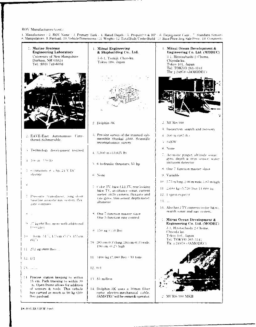
ROV Manufacturers (conOt.)
1. M1.anufacturer ,2. ROV Name :2. Primary Task ,4. Rated Depth 5). 1'ropuis:-'. & HP 6, Deplovment C'age , Standard ~no8. Manipulators, 9. PaYload, lo. Vehicle Dimensions,, 11. Weight/ 12. Total Built;Under Build' 123. Base Price/Avg. S;ale Price 14. Comment,
1. Marine Systems 1. Mitsui Engineering 1. Mitsui Ocean Development &Engineering Laboratory & Shipbuilding Co.. Ltd. Engineering Co. Ltd. (MODEC)University of New Hampshire 5-6-1, Tsukiji. ('huo-ku. :)-I. Hitotsuhashi 2-Chome.Durham. NH 0:3824 Tko14 aa hvd-uTel: (60:3) 749-6056 Tokok104 toapa Ch d - pa
Tel: TOKYO 265-:311Tix: j 24978 IJAMODEC)
2. Dolphin-3K %lt'RS-.3o
8. Inspection. sear-ch and recover\
2. AVEEas Atonmou o :- . Pre-site survey of the manned sub- 4 2)))) m 198.) ft.)thered Submnersible. mersible Shinkai 2000. Scientific
reconnaissance survev. 25 21 K k
Fechnoiog-_ development test bed 4,130m(1,2 t None4:1.00 m1082) ftAcolustic pinger. altitude sonat'.
gyro. depth & trtnt sensr, water5hvhdraulic thrusters: 55 hpnruondtcr
5.One 7function masteCr -.laverfthrusters a i hp, 24 DCl
piectric 1;. None 9 Vauriable
11) 2.72 mnlong. 206 rmwide. LS,-) mhigh
Colior TV, bokw 1LIAAV. rear looking I1 2.6hI0 kg 5.72( lbsi II Liotilkb&w TV. avoidance sonar, current
7 Pesuretrinduii-. ~ti ~r meter. stills camera. tluxgate and 12. 1 lprototvpe! I
),dsi ,iie acolistli- tOO lonttfl hl ~ rite Z.Tos. tn sensor. depth meter,havn couasti % fe altimeter 11
1.4, Also has 2 TV cameras color b& wI.
S One 7-function master slave ac oa n as-en
One 5-function rate cointroil I Mitsui Ocean Development &2-/ kLg t(60 Ibsi: itire with iddititinal Engineering Co. Ltd. (MOI)EC)
34-1, Hitotsubashi '--(home.1,5,i k4 (:':;o Ibsi Uhivoda-ku.
1 or llt i 51 'I ].;5)i-nt . 4 .'.-t Tokvo I 11, Japan16"1Tel: TOKYO 21i5-141
11) 28)5 cm 92;A' lottg, 194 cm (6.A') wide. Tlx: i2497S .-IANIO[F)90) c~m it; 2) high
1 1 272 kg (6(1 Ibsi,.
2, 1/1 1 1, :140o kg (.418o ) 33 /1 to~ns A.1: ... .... 12. 0 /-1
I I Precise statioin keeping to within 11 $5 million15) cm. Path tracking to within A10n, Open frame allows for additionif sensors & tools. This vehicle I14 Dolphin.:!K uses at 1)1mm fiberhas carried a.s mitth ams 90 kg f200( optic electro-mechanical icable.Ibvo payload. .1 AMSTE( 'will he owner& operator 2 MI HS-:01 %l MEI

ROV Manufacturers (cor)
1. Manufacturer 2. ROV Name :'. Primarv Task / 4. Rated Depthi 5. Propulsion & HP 6. Deploymrent Ca !e 7 " andard Se-1'r,.arupu.ators, ,.10. VehicleDimensions/ 11, Weight.' 12. TotaliBuilt/'Under Build, 13. Base Price/A%-g b ale Price 4 Coinei.
inspection 11. 600) kg 11320 Ibs) 1 20001. kg 1. OSEL-Offshore Systems
4.31 n18 t 4.400 ibsi Engineering Ltd.4.59)m12.5lt ') Boundary Rd.. Harfrevs Industnal
.4-:WO1W electric motor, .. . Estate
1: . ...... reat Yarmouth. NorfikIi. None NR31 OLU Vnited Kingdom
14. FOA SUR has been developed for Tel: 104981 659916 'Fx:4719'47Directional gyro, depth sensor. a- R&D and testing of equipment.
coustic transponder instrumentation and techniques for
8. one hydroacoustics. hydro-optics andnavigation. Watertanks are used for
9. 40 kg 88 Ibs) compensation of payload.
l10. .95 m Ion;. .75 mi wide, .7 in high
11. 2001 kg 1440) lbsI 1 OSEL-Ofrshore Systemslo.0i0l kg- includes truck weight) Engineering Ltd. i o
Boundary Rd.. Harfreys Industrial 2.DUPLUS 1112. 1 (prototvpel.0 Estate
IGreat Yarmouth. Norfolk :3. Multi-purpose\R31 OLI' United Kingdom
14 RV asDChrshe, otrs Tel: 10493) 6.59916 .TLx: 975084 4. 1,0001 m(:3.2801ft) unmanned 11m
pitching len, for TV and fiber optic 1.9 t and
tether c1ahle. . 6010 v AU units
National Defence ResearchEstablishment (FOAl T.Fugt vo et esr iS-102 54 'Stockholm. Sweden rllt gensos delth me or. 1l
TV.8.Two 0.1;E[ Lsandard rnuiplat r
one grabiber arm optiional
1) 100) kg 66ii 1) Isi lnniatinedl
2. D)RAGON FLY PM~l kg 8:196 lisi manned
lI (. 274 i'mt 018"1 lon4, .: cm (6,-31. Multi-pu rp ise wide. 1:16 cm (-)41 higzh
1. 1.828 in (60001 ft) 1 17001 kg !:,7411 1b~' In
5. 12 -;ervo controlled thrusters: GO1 hp 12 t; 1 fall I buiilt are nT serxicel
ti. Standard 6 iroulerat ins he low:115- In I . T
7.Fluxgate gYri.. depth sen~or. iutch 14
& rill sensors. alt1imeter. soi.r, __________________
cilo VYb~wSF1 '\ I1. OSEL-Offt-hore S~s t.m
5. wi OSEI 1,T-funct ion seawat er hv- Engineering Ltd.draulic manipulators Istandardl. HOtnilarN fid.. HYiTtre\% lni~TI& I JjiI
Ft IA SU B One teles-optic grabber ioptionall E..tate
& I Great Yarmouthb. NorfolkR &D 9. 4-50 kg 11,0(10 lhsi (with additional NRSIl OLI ( nited Kinvdomi
4. 250 ITT (8201 ft) buoyvancy material) Tel: 104920 ki5'9)16 TIx. '17,1o';
I hydraulic thrustersz: 19 fit 10,. 2 54 n1 m I~ long. 1.8; m Il1' wide,I,()-, i 2 high
TVcmrdepth setisor. altimeter. I a I t p roi ix)i2 tn
avoiudance sonar, gyrii conimpiss, at-titude sensors. 12. I
8 . O n e s im p le h d r a u lic g r ip p in g a rt1 : 1 ,1 1 2 ,01 1 01 1
to he instailled II. Advanced teletinet rv vst em w i liti.
9. wI kg 091) IbI call filier data and video transis-sion lines with auto switching Ii the
1I 2 nt 16.61) long, 1,2 mn 14) widle, 1/2 Ti even ofpimarv svstemn fiure. Mod- 2. HORNFTVA SP AD)S ltnosphet'1.2 in It') high I ular conistruction. L ic, diving suit I
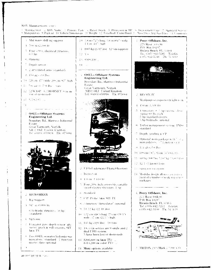
NI'idl(C RM i dle in \eii,u, nw~i I . wd'~i1 D, iii Pr'idm HPii kiI , HI)-- Frnent, ~ ~ Ill-i
N\ % i llw r dill Il- Hn Ip I I I .'s In (7 2"11 Ing. 11 1 i4l" ide. I Peir- ()ffshorc-. Inc.
I P)W, lh~j F2 0) B',, IW-1 4 7limi5 12i22-l eletrca 2hutj, ilii Ii4)iiIX R{\ -each. FLI ;24
I; 12 Ii: K14l 2 '4'52641 Teiclix.
!- -:: O.i(SEL-Offshor-e S vstemsEngineetring Ltd.
1. 12\V.SP '.H()HNFF Iii \R~ii NI F OIJ nited Fxin,,dnn.)T ! d---tI -,%fil 01 91 6--991 TI nd lh x: 9 711.,. 2 RF-(2) IV
OSEL-Offshoire S\ sterns i lii
Engineering Ltd. Shp -Ianaidi t-cli,
P-lid r -d.. Hii~rfrv% - Indntitrial. lip 1xdilvlh ip ., l
,F- , Tate IntilKnrdi
Ht'I YiII' Oni1 NIik ~--, ,j1i-
2'I -i ~
R 4. )IA I i .4l iI, ;in ,r- Ia a n
FU4'FIX.E I iidri err ffshr ITc
I -ti dar ii I in It \-: to r Fk i I~ IT i-n -I-\ 5 r 11 11 ,
ii 1..7 ti 2 1 ) 1 11 1. 1
IM H ) K E xnit,'ril ix de t Inri-ir O ffiti-e I--
17)8 2 -, - -4.
1 TaidaFrdlua II I '-ren -ul cl -V)
Ia.I SEF.-~i~.ti' i\u~~alii- id -h~ac itanin? h 1i~t~'22~iiillii~it.-tan~rF7 tiriiiiit F 1 $2-i4.~aI Iw.FiAw'F\
I I, nn I liiii riall 2g lHF )>11 lh12 11 I'mk ~-,% ,, depth.I- vnI,, a4t -7

110% Manufacturers 'cont
I MlnutacTurer 2. ROV Nanme i1 Primary [ask 4 Rated [)epth -). Propulsion & HP 6- Deploym irent ('age 7.Standard SW"!Mankplatnors. Pavload I0). Vehicle Laimensions, I I Weight ,12i1Total Built., I der Buid 1:1' Base Price Av g Sale Price 14 (rn-o
1, Heavy duty ROV Work Package .4 .. I Slingsby Engineering Ltd.*Platform maintenance i )kIIIIIKi-hvtnoorside.Su ihea production & maintenance York YOCO 1; Z t ni ed Kigd'!
*Anode attachment 10. 6io 2 4 0 .. n 18i , 5 20 m m 121) C ,:e 10901) 76977*Drill rig Support ri mm 26. 2 ) Tlx: -.-,9 1 1 SHL I
4. 1,00)1 ni 2l.:1) ft.) tp to :,(III) mn 11. 4 7 kg1 102.(M Il hs Note -no photo availahie
110)0 ft) optional12 i)52.CR(
5. 6 Innerspace 1002 thrusters (3 (a450o Wei thrust; ( a 180 ibs) 1:,. S8mii hM-w TV) or 'OlOcolor I. C'able Burial & Repair50 hp hydraulic 1t)0 hp hvdraulic TV) . 4 1000)1 in W2 2a ft)optional I4
- v rui h-:-,r.I,,h6. Tether management system lI 1Lo
standard - \one required
Heading, depth, altitude. pitch& roll. 1. Robertson Radio-Elektro X/S 7 C'able detection svtei.h * draulic pressuire. hydraulic fluid P.O. Box .5.N-4 i T camnerats, oinatr. traw ipt oder.puetemperature Egersund. Norway dletector, magnetic ,niopa~-
One Hercules .5-function manipulator Tel: (014) 49 17 77 Tv, SRI. TA: 7 un itrn mai-,tandard O thers optional T1 x: T1: 19 slav
22. )7~ k,-1 :I)( h~ increased ;iayl.ad Cal . . ,',..-Y
I) 244 ~ 10 long42c 56t_)' wide. i .. i'l',oi -I'
cm 172" high wide I n .5 10 ' 'm it:I
w1 I c I S k m 1)) lI
BI1 Btvr can choose from a large mnenu
A4 v -rins and work packages, thrust3ill. MatOM. Coniputer color graphics. 14. Fiber optics are used for dzit.i triolB I'llN is designed to carry work missioni.ti)ickages larger than its.'l: morepower ii I smaller package than,her ci inpetitiye systems. I Slingsbv Engineering Ltd.
_______ISPRINT 101! Kirhymoiirside.
lt.t.Ic.Ispiection aund light woirk York N06f IiEZ. I toted Kinzd ,TD
Q. I Inc Tel: M0i4) 76977720..hm 610 in 2.010 ftt Tlx: 79 11 SF1.1
\Iinii- Yu kigavaObta-ku. Tovko -lapan li 5 p electric tirusters: 2.5_ hp
f; Optional
.Aiitii heaing & tnt.. depthI
I -tiinitim h\ draulic iptiiinal
1 6 hlttn2 1'). 6 1tn2 C . .4 II 1'1
I 15 1; kgl.I1S7l1hsI 140ikgl:7, 1lhs;I
12 1 i priitiit~ pI 20)
I Inspect ion ,Ivca stadad fetr is dule 2 1 NS 1)F.(70, OR
111200nm 16611 ftl camiera (icolior TV & sil cattivri 2Inspectionthroungh Nin gle lens I lnplex camnera
DC mo'iitior optionial I idi low-light-level b.W TV 1610 in 12.1000 ft)I
I;Optional camera through sitngle lends . Iotur vanable it ch electri t hrtiste rs.SP~RINT IM is sitIthrough Benttex 2.40 V'AC mtor7I)tepth & .izintiith besrl&w i)r A,,, S Norwavi. Betncii Ltd. ttINI
cIi) r TV and Perm Offshiirv. I.c, tt'S) 6 IIOptional
A ________I
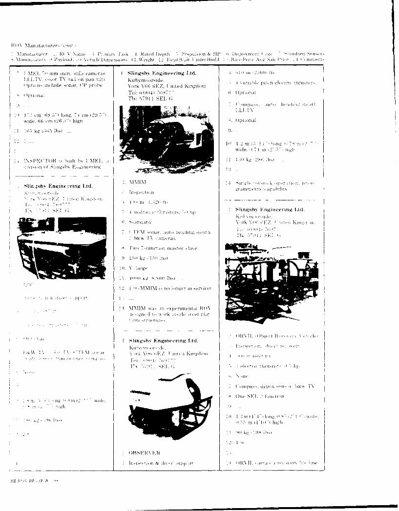
Li t Llt J It 1Ier I- - 10 \ NillVi. I'ri.rx I .i-i 4, R id I)eplii ., l''_-)Iip ll & HP' 6' 1h1IIamI . l a rdi>~i
I MtEL -, ni te( til ca cr I Slingsby E ngineer-ing Ltd. 1 1;( Ill 12.110H~ th
iptum tIide -onar-. CP~ 4)tohe. York Y06t tiEZ, I nited Kingdom illhefl(f l- 11
Tel: (094)~ 7619777 Ti 6~ tinudlid
1 Tlx: 5791 1 SEL G
l.L[;I1A''12cm '.4lorng, 74 cm .1wide. 664 Cm 126.-,- hiii-h Opt inlI
10( 12 in k 1" I k Ill. 7- ntIde. 1.4 Il t I i'01z
I.\ PETO is 11111 j hlt b% tINIF I W.~ II11kg (2:-t 11),i
*-'i.s % En inFl rn Ltd k vili h-~,r~ ,Ii~igh nic'ig Ld
I4 lI t I I I
11 Tc Il --. -----.-
A S F1I\ wi- nIuh -xrltur" lrel)lii
M A W iil~m Y1l Il- l mi11 KI ''II. Ill,
b&42 1AI
9 - kl. ) S i:\'I' lls
tZ hi h 1large
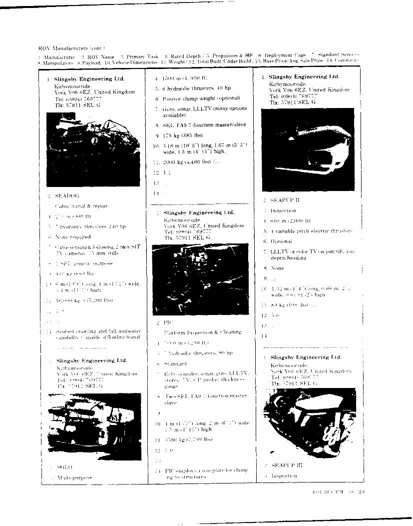
R0 (.)V a nofact orers ( ontI.
IManulactutrer 2-. ROV Namne :1. Primar-y Task 4. Rated Depth .35. Propulsion & HP ,6. IDeplovirment C:age -, Standard 'Sen-
k .Mantpulators i. Payload lo,%Vehicle Dimens;ions 1 1. Weight 1 2. Total Built., inder Build 1:1. Base Prii-e;Avg.. Sale Price 14 Cnitrieni
1. Slingsby Engineering Ltd. .4, 150) mn 14, 950) ft) 1. Slingsby Engineering Ltd.
Kirhvm-oorside. hdj4)~Kirhymoorside,
York Y06 6EZ, t'nited Kingdotm o hr~es York Y0)6 GEZ. I'nited Kingdcotn
Tel: 110904) 769777 6. Passive clump weight loptional) Tel: 10901) -69777
Tlx: 517911 SEL G Tlx: 57911 SEL Gu4ro. sonar. LLLTV (many optionsavailable)
A. SEL TA9 7-function master/slave
9. 175 kg (385 IbsI .1M) A-18 m 1 10' 5') long. 1.67 m (5' 5")
wide. 1.5 m 14' 11") high.
11, 20)10 kg (4.400 Ibs)
12. 1 1
I able hut-iril r~epair 2. -SEAMP 11
t " if o fi I Slingsby Engineering Ltd. InspectionKirb% tooorside. L4 6il) m it21)) t
7. horawi, inni-ters 240' tip) York Y06 6EZ. ('nued KingdomTel: 00194 769777 5.4 variable pitch electric thriiso-r-
G. Optional- I) Iit ~e 9 1 toI Iow-in. b& iw SITIA imet i I m stills 7.1.LTV ,or color TV in pa10. tilt. now
Fl. I-era pu~iiorpose depth, heading
8.None
f; mIn lon !... 4 Itt 1 2"1 wide.
i. 4 ni ' nigh Ii 1, ;2 In 4' 1 ) (16. .0 In 2
16.'Om~~1 k", kg ]f) ) de Ibs I.) l
4 -a v , e -t1,I r in aog h0 ill lutolwat er 'ljttorni ljii~peition & I leattiti,
00 In ft. S I
irltlic 1hroT-rS. i) hip
SlingshN Engineering Ltd. I Slingshv Engineering Lid.
,IIi~.) 7477 .till I . .11)iI'i4 Ili.11,1A Y1el ui l -'Z II ue
lx 17. FR. 1 11g. DX: T71 I II. 1
10l. 1 tot iI : '. ) roiz, 2 inl ik') T %i dv
1-3 In iI I I 'I high
II ~ ~ ~ ~ FA 1.311 kH!.i11l.
NU. f-uto , 'Icpi1cIr al
- 161 p( i rpo- ing\I to I i(i u p c ion

ROV -Manufacturers' ,,lo,)
ManufactuLrer1 . RO% Name , Primarv Task 4. Rated Depth -,. Propulsion & HP 6~ Deployment Cage -- t-andard >.ensor.N. lanipuiiaors 9. Payload 1I Vehicle D~imensions 11, Weight '12. Total Built I oderBuild I ; Base Price Avg. Sale Price 1 4. Comment,
4, 6 1io m t2,Utul ft) I Slingsbv Engineering Ltd. 3, Mine counte-measuresS vrblpicelcrchrtesKirhYmoorside. 4. 150 11.0
;aralpicelcrctrses'turk Y06 6EZ. I. tited Kingdom 'miL,)it
8None Tel: (0904) 7677 5. 7 electric thrusters. 71 kvaTlx: 57911 SEL G
7.Auto depth. heading. color TV on f.Otoapan, tilt. 70 mm stereo stdls cameras. 6.Otoa
Auto depth& heading colorTV. 1b&,SNone TV. 3 spinning mass rate gvros, 2
pendulums
8. One 3-function1 7: 7) lon V 1g. () 7 r(2 6)
%%ide, 0I.7-, tn 12' l high 9. 11) kg (22 Ibsi
1h') 65Is, ~ 10. similar to, SEA OWLi
1list ordjetro ed, 4 remain tit Till. *, kg, (IST lbsi
2 'FRO-JIAN 12 2 1 4
5 pvia iiivcature i. all-rounid visin 1 I lrilliniz support i inspectlion)
0 ItieYttnh f pei iii pan, tilt unit.4
4 i) t~rit :1.28' rs 01ti
Slingsbv Engineering Lid. I ~daii thStes VT Ei C USE( UAKirbtmoorside. Opti, ti 2 'Au ,dland I )rie. NW\N
,-r- 'ill l Lnitd K ngd m %'ti.hingtot. 1) CI - 2 i i W'ik004 ',,6 F;.I iedmidot Auto pitch, roll, depth hvaiig al lei: (20)2 6251 10(h, lx, )l,141i7-l
F1 x. 57 91 1 SFE1, C ' titinle. -mol 1.1,1,TN . gvrum. trrckiti,-pinger
On (e S l.',o A tfinitioul-e
One.'4 1 VA1; hrc1,1rle(
trolled
9. 91l kg '2w,) lb,,)
1). *'. 2 mn 1 1) 11i, 1 h To I I aId t-.1L6 mn C, highbo
1I1. Isill kg 0.11iIh
sl \ iedi~ Crawler V'ehicle) 12. 1i 6
Shiloasater harbor, coastal and 1:i .."-l~r Instl\, cal 1 ijlitng In k rill rim- siippo ri
,I' 1m. ewar outfall inspe(,i I4 ['BOI0,AN has full diagnt)st ivn1ring for elie ,t tiaitenitice 35.(l, in I1. Io t
rissar 'rack, 17-- kt, irmittiv 1trcc
1. SUTEC USAN. 'f 1 irel IS812 Woodtand [rive, N W
dep;,~. ,1 th M 1A[' Washington. D.C. 20008 8.Te: (202) 628-1000) . Flx: 994o7,11
I ipt till9.
tit C,5 P TIg, 1 11t, 1 1;") II.
Idl, oh tit( I 2i high 1 .2
:1.
14. Performance specson HA11\W\K
tnot ii aillab 1u; ai-ls. a s .
O1WL .vstvni with I trotmgei hilil
2. SEA EAGLE Ha.s reat lokitg VV laitiera
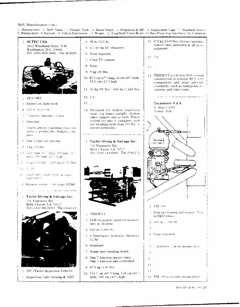
ROV Manufacturers t(coot.,j
1Manufacturer 2. ROV Name :!. Priniarv Task ,4. Rated [Depth ,5. Propulsion & HP 6. Deployment (Cage /7 Standard Sens,r-8. Manipulators, 9. Pavload 14. V ehicle D~imensions, I1I Weight, 12. TFotal BuiltAlinder Build/ 12. Base Price/Avg. Sale Price '14 Comment,'
1. SUTEC USA 4. :18 m 1125 ft) 11. 675 kg 151 Ibs) 129 tons inciu le.,2812Woolan Drie, AV.control vans, generator & all all e-
Wasingoodlnd D. \o 5. 4 1/10 hp DU. thrusters qui pment)
Tel: (20)4 628-100) Tlx: 94059 6. None required12. 1
7. Color TV camera
8. None 1..
9. 9 kg 21) lbsI14, 17RIDENT is a hvhbrid SM1 . ,tern
t0. 67.5 cmi ('27') long, 50 cm C20-1 wide. constructed Of reliable RCV I7o.52.5 cm 121") high components and other in dustry
standards. such as mnanipulatc rl11. 4:3 kg 05s Ibsi 648 kg (1.440) Ibso cameras and other itemns.
In'.pec tion. light work 1:, Tec'nomare Sp.A.
4 .i 1 1.)1 1f I 1 fo hallow inspection Veice. ltiak
- taks eg. drns outtalks. ;hallmASciectrc thruster . k%]lksitnesad so forth. F. tinri
01monafll m;~r fit Ino9Containers eachrio wighngmore than I')lbs t,
Dept ) I etiror. 1 spinnn arae esrrpraiw
()ne 2 tutotiun optiona Tayor iving & Salv'age Inc.
4 k' I' h )7 lEn ie Rd.
4.-)ri 1,- -om ' 1 !, " -(llt mmt~ lisl'41it50 1:9460
rr. m high10
4, I) ,. 41, p TMENTE ;
Fa,6 or Diving & Salvage Inc.7'til rivmreers Rd.Belle C hasse. L.A 71m4:17
Drill rrig rigorz lt'piniii nitol mo ,
Iiii && I) pha,'
G.4111 M 1'2.110nlo 1t1
54 tinrer,4pice hydraulic thmistvur,. \M lilt' 0(11
12 hp7
6. Standard S %,ud'r Iwrk llt.imi~ii-P~i
7., Sitna r, ato headinig, depth
8. Ifne 7. function master' slave t
One 5. foni-ti on rate control led
2 IV iavltir Inspection Vehiclel .675k 10l
144. 152.5 cmn (61") long, 1204 cm (,C
.Inspe'ctitin, light ileaning & NI)I wide. 1444 (im 441) ) high I, m I'Mk de-i i inyo'ign h"
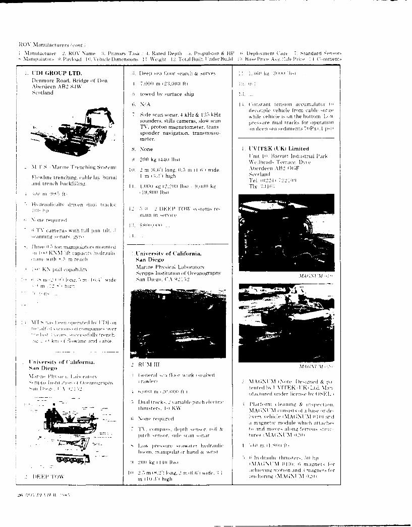
RO (M \ ill fact urers (con t.,
I Manuftacturer 2. NOV Name i1. P'rimarv rask 4. Rated Depth -,, Propulsion & HP 6i. I)epl.,vntI Cage 7 Standiardi .ensor,NManipulauors 9PaNtload Iii \ chicle 1)irnensions 1 L Weight 12. Total BLIilt I oier Buildi P Base Price A, gv. ',le I'rie 1 . ('..rnynenl
1UDI GROUP LTD. :i. I)eep sea floor search & survey I.:jii ki, [25m11)'l
D~enmore Road, Bridge of Don s.7M0Ihj:MOfip IAbterdeen AB2 8 .7.0 m2.00fScotland 5 towed by surface si
6. N/ A 1. C onstant tension accumulator 1decouple vehicle from cable ~ig
7.Side scan sonar, 4 kHz & 12.5 kHz while vehicle i~ on the huttornsouniders, stills cameras, slow scan pesr ultak o prto
TV, proton magnetometer. trans- on deep sea sediments 7. 11a i.1I p~isponder navigation. transmisso-meter.
8. None I . UVITEK (UK) Limited
9. 20 kg1440Ih)I'ni li). Barratt Industrial Park9. 20 kg 411 bsI elllheads Terrace. Dt\ce
M NIT 'arinie T'renching S\-vtn 10I. 2 m (6.6' long. 01..- in (1 6', wide. Aberdeen AB2 0) F
Fliretrenching cahle lwv hiiriil I m i .n high Scotlaind
.1md trench hackfillinio. 11. 1,0)0 kg (2,20o Ihsl 91001 k4 'FIX: T7:1l
100 ( I n t9l 7 ft) 19,S001 Ibsi
- Osdraulitillk dris en dual tlacks:hp i 1. 2 1IEEP T'OW S vs IT-
tiill in srvicekN inc required
TV 1W caeras w~ith hill pan tilt .
-.cinnin2i . inar. 'ri1.
Three I.ton mnlipiitor , 0) Lint ci,! m KNN lift capaicity hdraulic I .Universjil of California.
rmine with i.5 reach San Diego
KN pull capahilits Marine P1hysical LaboratoryScripps Institution of Oceano.-raph% M. \N 1
i I lo ,,. . in i 4. w Id e -an IDiego, CA 921-52
NMl a , -'iw tiertvil b\ I [IIolit vr~li ( ii 'ptartie-iver
.. ,,-t . . ar. icv.s-ttlls trench-
k ill 't t],ilit irid aibip
Iniversit% of C alifornia, I'III,,ft t .~bdXtI'
-4aln D ie grotr M AGieril
N, r fi). Initit i n ,-i . it va I'airp h iar:l \ IAX;I N N i Note lDesiuzned & paNmjr Di cs, A 4. F) tented h% I VlTFK .Ii l id lait-
) oii i ,21.111ft Iiuactired under license hv) )SEI.
- - S IJiial trac(k-.. 2 variabhlv piut h cli ti Platformi (iearitt & inspjectiont.-. thrusters. I it 1W MIA ;NIN'M consists ot a lhier de-
k7Nine rtiluireil livery vhicle iMNA(GNI'NI o111 and
aI magnetic motdujle wich attache-.7IV. cominpas,, depth ets~.ro)l to id move,. along ferroti- -t rii-
* I pitchi e-etir. -nid can (-iar tires N\tNi NIIM 0121
~~ .8 ~~~~Low Iir4- -irt teawiiter hvauhilc )1ti1,)1ft
hittm. tnanipijlat ir hind & wii-t6 \I uictrsv , tll)
.. 9. 20)11 kgz -i 1i lbi NI.X)NI'NI HIM, 6 fltiaet fir
I () 2--)in 114,2) lo g, 2in \idv. IitItievii tiiit iin anid .1 magnets for
'vow ~~~~~In I 10.31) high wi!MAN'02l
26 1"ti 1 f 11 1 1 It ' 9
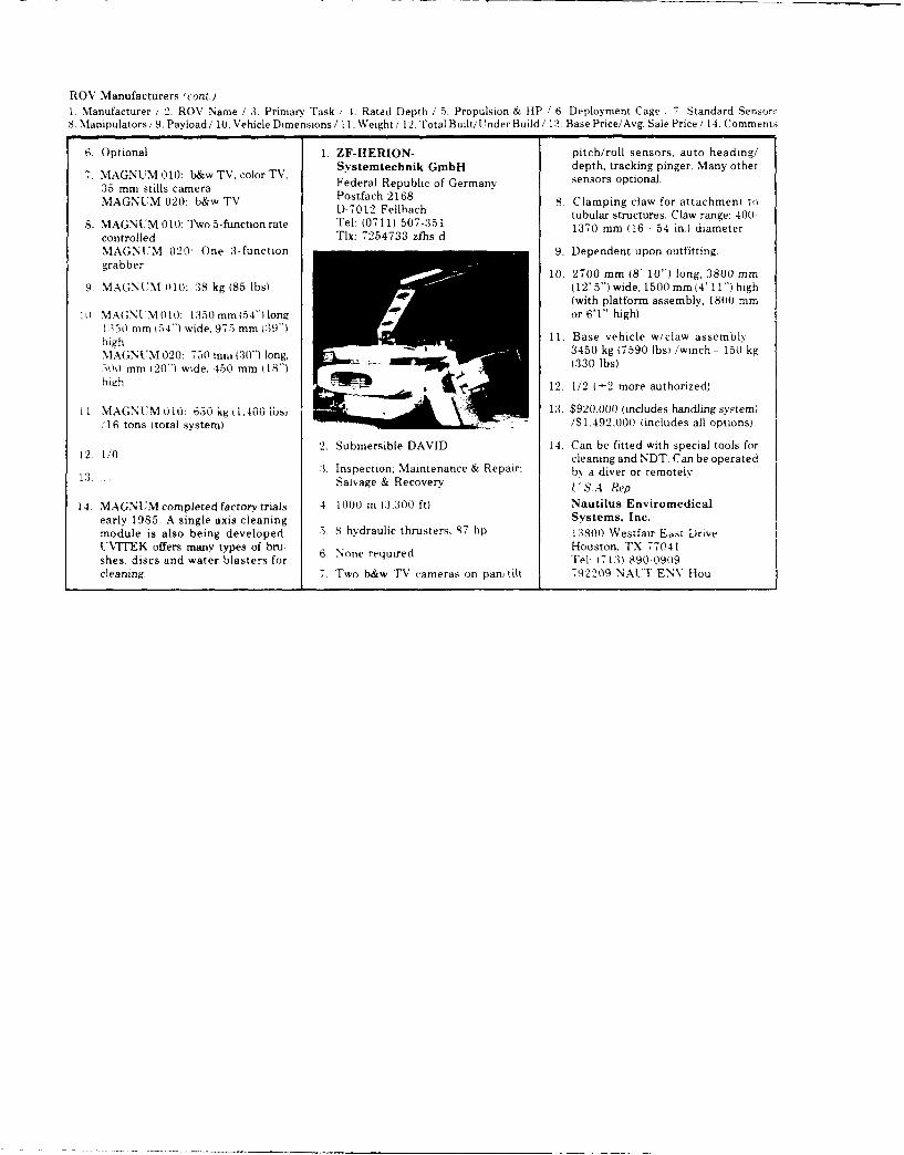
ROV Manufacturers (cont.)1. Manufacturer / 2. ROV Name / :3. Primarv Task , 4. Rated Depth / 5. Propulsion & HP / 6. Deployment Cage 7. Standard SensorsS. Manipulators/ 9. Payload / 10. Vehicle Dimensions / 11. Weight / 12. Total Built/Under Build / 13. Base Price/Avg. Sale Price/ 14. Comments
6. Optional 1. ZF-HERION- pitch/roll sensors, auto heading/7. MAGNUM010: b&wTV.colorTV. Systemtechnik GmbH depth, tracking pinger. Many other
3. MN 010: cmr T.colFederal Republic of Germany sensors optional.:35 mm stills cameraMAGNUM 020: b&wTV Postfach2168 8. Clamping claw for attachment to
D-7012 Fellhach tubular structures. Claw range: 400-8. MAGNUM 010: "1wo 5-function rate Tel: (0711) 507-351 1370 mm (16 - 54 in.) diameter
controlled Tlx: 7254733 zfhs dMAGNUM 020- One 3-function 9. Dependent upon outfitting.grabber
10. 2700 mm (8' 10") long, 3800 mm9. MAGNUM 010: 38 kg (85 lbs) (12'5")wide, 1500 mm(4' 11") high
(with platform assembly, 1800 mmll0. MAGN[M010: 1350 mmi154") long or 6'1" high)
1:350 mm 154") wide. 975 mm (39")high 11. Base vehicle w/claw assembly -
MAGNUMI020: 750mmi (3() long, 3450 kg (7590 lbsi /winch - 150 kgMA~~iNU6- 02:7( m(0")ln, 330 lbs)300 mm 120") wide. 450 mm (18') 30bhigh 12. 1/2 (+2 more authorized)
11 MAGNUM Oi0: 650 k t1.400 1b, 13. $920,000 (includes handling system)'16 tons (total system) /$I1,492,000 (includes all options)
2. Submersible DAVID 14. Can be fitted with special tools for12 1/0 cleaning and NDT. Can be operated
:3. Inspection: Maintenance & Repair; by a diver or remotelyL3. Salvage & Recovery S.A p
14- MAGNUMcompletedfactor 'vtrials 4. 1000 m 13.300 ft) Nautilus Enviromedicalearly 1985. A single axis cleaning Systems, Inc.module is also being developed. 5. hdraulic thrusters, 87 hp 13800 Westfair Eht DriveUTEK offers many types of bru- Houston, TX 77041shes, discs and water blasters for 6. None required Tel: (71:3) 890-09(9cleaning. 7. Two b&w "V cameras on pan tilt 792209 NAUT ENV Hou
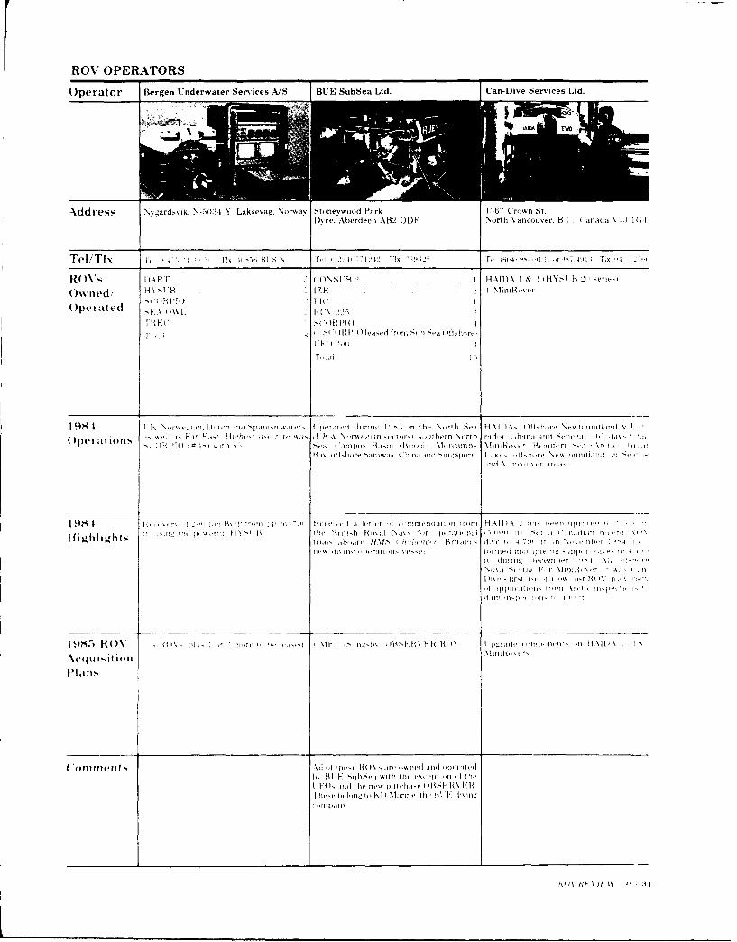
K ROV OPERATORS
Operator Bergen Underwater Services A/S RUE SubSea Ltd. Can-Dive Services Ltd.
I-I( s 2\ C ONSt B HAIDA I & HNS stB H
Ow ned/ H)t Bt i 2 MER
Operated ItFI': H\ I. %. ki 22~ I~i r i ~~I SCODRPIO
I~~~~~~~i 9Sit t I- Ktth flwie du-',_ !4 in:t -rj Salk ,&
1- ir . i~t []Iiih,'. i-t'. [iK rmltr In and " -t iI i \ i'
I'R 'l I h iii-.am.i iIi Mrlnb it ,,,rA ,i -
,If~tl('l I il hiiiiti pt--. Ilt Laki Ille ,'tii
iin \tttip;, l 1tt11
1 ~ ~ ~ ~ ~ ~ ~ ~ ~ ~ ~ ~ ~ ~ ~ ~ t i 9/- 41/ !r ''t I- :H41,dIittrImnnaimfm)H t2if'
ROV Operators f cont.)
Oper-ator CanOcean Resources Ltd. John E. Chance & Associates, Inc. D~ominion Diving Ltd.
Photo Not Photo Not Photo NotAvailable Available Available
Addr-ess tilt Derwent %Na% P 0 Box .5,1029 145, MainSi\e%% Westminster. B.C. ( Cinada V4M.% 5PS Lafavette. Louisiana 7o5o.5 1)armottth, Nova Scotm. Canada R. i tit
T el/ TN Fet 1;041 ',24 44,' FIX ''I ;-I 1'e - i 21- - :111 TIx 5 t
Rs' CUPT'1O #0'tti hIR VEY S tB #1I & 2 1H YS VB T V e 2)corp i #19 1
0"wned/ !operated as a dual Nstern VKI\N III HY,'I*B m'
Operated
1 9$i-f imnptx Basin. Brazil Mobilizedm ' e~sei Operated 7.5 'jay' in rhe Gut f0 \lexi,, ( imid 'rcoT
)perations' 4 ia' ,. performied hi1 tixes Ixipei et inspections, [ipe lie as-itt I ts li'ehtti(,m suivers, and pliwt diontueniiii '"peraltis
9S~ I Eboali-,ed iwieil-in ah!le loi n lda- 1,' o t i ie t io ineni tihe pre(iv- i Re er\ A. chain
I. rm iindern-t th FlIelto J' aN --xel Clear lioi lhr rererding \ ind ) -xrdiitues d !jpiln ~~porlt tC-Highlight tdewrit m,~ Ii r-id ket tree where an amhnor hm had -tlied irtth -P
1982 l{( I\ fi.tnr md netaii xotIial tlt STwpi e ditniRdS-'e
14S nIM nieh nv Ii)sra,6m (% di'niH \f
\cquitlF ion4

ROV Operators (cont.)
Operator Duikbedrijf Vriens b~.Eastport International Energie Diving Service b..
Address Van K~nijnenhurwme,, I.-) ob;Bldt'0ox2
Ro sRt)\ Illll 1, '. Nav f)F.FF r )RO'NF II ')1
Ow ned/' AT I S( A RA( R I I
Operated
I U I .... .. f
Ir raner a t i i hI e 1v irit e , n t on I it h
bpell 1 )1 N '' .1 ht' > I s v1'.
Acquisisir
ROV Operators (cont /
Operator Halistrom Holdings PTE Ltd. Harbor Branch Foundation IUItrational. Inc.
Tel/TI x 17e 222 '4,' 17~ 2~' HALLH() Tel: (3i05) 465-2400i Tret 2 12 _$-i 6i1i T11 47242 It C INC t'iv
SEAS OlWL RO%*s CORD 11 (Cabled Ob~em-ation &Rescue RECON lIlA I oi,
O nd!Devicel RECUN [V 1 )( ii0w e/Roy MANTIS ~ 2-mie'it
Operated T.IPTER RECUN IV 2.'
1985 pirated ffhore S, Lthvat Asia jnd Worldwide operatioin, It Rt\ V.UA>
)peal~ 113 nli-.and t.u hmer~ible fleet w ere IM f1% ,il At ti jardd ,-. itteration dtirm i,! !1 1
198 5 .~~. \ RU \I.ANTlS installed ind mapl
Ii 9S Iani -. tme',,I kh pedI iti p Insvecar ea af~i~~igh~ ttt for the remnat df a welhe ad ani -vIfi hliht"trie, al timol from the oeafl,wr
Drm a -titract fir Rrown &x R, if-'hire 4 a!I,rnia. it *-. REi4IV -il
RFA ON i-rd. lor -ntipm..u.diiv e eents if\ iS rkin. i- i.vc -i-mi-Idtiringza total 4 27.1 1hotrs. I miniles in --1111"e ()to dive lastedl _j, u hour-. O li n-
'4 her iot. als . 4ffhire C,it irila. illIRECOiN lV made It irm2ds sdir1ng.3
t~i~4 hittiu tne t7Ihiiiir-i nd '! nirm.
1985 R(V %%T I. itI 'ir iwra~ -iv IA i -till, an,
\cquisit ra. FA )\\I, ha-. irone-d "i h0,. a Ol
'ofilmerit ., 44 Rh 11 lids teen) re-/,riitdni i ftatt.(I i. C iii.l,. it- I fdvrs.1tt,r vin Rt V Nii or. tp.i, r tievritionm, I .iimitt: I intr if) Ilusii l- It :iiin.: I 4. upletv with artii.i NO/\ -. tvmi in t4
ind 1 mtannited suh- i,.e \i1. lleaner MiK
I\ mid. Miermtaidl 11 \muc If this inijr,v,.'I'ti raed trom [I /s, 1/5k ;I ')H4

ROV Operators (cont.)
Operator KD Marine Oceaneering International, Inc. OMIS
AXddress Ilitmedden Rd. Industrial Estate. 160)01 Park Ten Place 19407 Park Row, Suite 41)10
Dvce. Aberdeen ABR2 ODP V.O. Box 2181:30 Houston, TX 77084
Houston. TX T:7,218
___________________ Th ,- 01 oCANRN(; Hot.-Tx55.5 )I
ROXs 0BS ER VE R DART 4 PROES im, PROES 20o
Owned! F- 11011YDR A
0peratedORIONR(V 225..
CR OS C O P I O"EAPTj 4
9$41
O per at ionfls
Ifighlights
19S5 ROV
Pla~ns
C omments O)eateering ls1k own' and pierate, 2
were vhieflv ng support. ighlights Includedthe revord~setting ADlS (live ii the 1;if i
%iext if)t 2.010) It
O cea neong tiwns and iqpe rates OCF EA NA RMS 1)e ils I ', P ratIe it n 1! 4 -.61 7
ROV Operators icontC.)
O)perator Saivage P~acific Ltd. Sonat Subsea Services Inc. Stott-Nielisen Seaway Ltd.
Address P 0 Box 30552 P.O. Box 4428 P.O. Box 9570tfa;int, Fiji Houaston. T\ 77210) 4428 Ezertorget
Oslo 1, NorwaN
TeU~TIx Tel 61 .2, Frix. FL Ye Te[: 1713t '140s-4000 Ix. 7751 i9 Tei 011 ; 152 so TIN.75,
R(k' )\BENTHOS RPV 4:ms Mi nso r si er.4 f 4RV 225
Owned/ RCV 1--.....'OPI.R CV 2 2.' . 6 S EA HAWK.
0 eatdRECON 1V.. 2 SE. A'Iil.
SCORPIO . I SL
198-4 Te-sting sff t ua Harbor FjIslan d, RUA ipe ratfins fromnsall re is sna io perat ng SOLO operated es o) sa tInthe N sri
,~~- I )tveosi the hisicrsrt! wre ckothe Iis.nsj i-si bases-Hs tsnXsrnit.Is AeIe. on pipeline inspe i-on & ron e 6c1 -a rancIlx0pert~tionsf, fs orthern Queensland. Ausirii (4 rptse Chiristi, Hinia Ab-\reeino thle Nosrwegian sector sit the North ei
floe on the wrec-k ss tie F.t'iAfi:r-ts tspsr, andi Perrth SCORPIO performed fl1, e-ntr, I, i
de~pth 4sft(;- ft.. h, ins o n the Lihss Nosrth Sea. Nlediterrane in tf~tisr, \I,,,Ri-sf n th, 5i,5 ra I Sea stf the -io sirx ino CanadaCsa-f [-WV 1257 Nsr-tls <i !sie sss-strot,
S EA HAWK ssperaiesi s the", Id-( 5-i
stoiisz Mobtil F xpssratisn, 55'.a%
I 9M I RtsP% 4 .1 ,hrauitis nedJ IMnUS~dhoto ftistss the \csqsiisii iit >i V,- ( ssis'msass r Folr sxiek -i mine clea r ins e sperqtits, i
I lgh ih si, t s he enfrance tss the harbosr as sices :~nlssn'i sts.ieeait ~s hi Nsr%%s'ziaii eciton )t ne VN~>sos.ght 1 the ifial i t ii-Ppth Nsac f5t (*HAILLEN( 1 R Asliissn ,I [RIt% !,5 sitil -i SiURPI(s deplosi-I '-tm INe N,
:*i- n hi .sije F'iae 41fter *xplanafti'I' "'&H 11siut - i fs'raiststi isk si it i % S .q~si-it isis 5 ii i -isif ,.haitsi isrraf's menansi, '- talavi issnsi 'lss-ei >i-rssse pIiratd-i tisin ;The sss,'s* '
1985i R('\ nsnhsitt oxfiaisin -)I -IsrIisiis i- -ti
\'qu i~ition I 555 ins Ri IV fleet. niidsiti tse 55w
P'Id it 'ER10 5 Isfhire
lines wre uniresesd h% tI \iei~vn
114 UttPE VIA'i Wt498.5

ROV Operators (cont.)
Operator Sub Sea Dolphin A/S SubSea Offshore Ltd. Switzer Salvage
R( Vs P0NEFFR anid SC012 H SiuH IIR S LI A L RT
Ow nedi INE
Operated >'I 'WEV re-'nmed (flit -i'Ii '
\'( li; >: ,renlir .4 11(1 Ii t
I 9S I Dali4u p r~ ,fV em] Ki' - li fhvI
- 11 Ir I I , " \ T- , I I ,! -I I: I r , 1 ! , ir , - t' , I t - t C .
)jw I z in ean n - ,, in i T- - P: - 42-.. n~o ?,, ai i t, J - iu--rtt

ROV Operators cn
Operator Taylor Diving & Salvage Co.. Inc. Underwater RecoverY Specialists. Inc. Underwater Resources
d id res~ F ne, r, Road S40) Hermann ',. Bo i.1111j Cha:i, . 1, I. lotami ,10 Pont ( %quitlan. B I i.dv tte. C'A 94.,4
an-Ada %:; W4 lE
T~e d -- 1 1:1 (,i '
If )[wrated ~
"I w''V
1\,M IU \ 1:- ,1 NI.. 11 !j IU I N i ' 1 111.c,. 1it ;ur I I I- , w
'Ii'A

RO\ Op)erdtr i" 'fil
Operator Wharton Williams Wolf Sub-Ocean Ltd. Comex Houlder Diving Limited
OeraTed I. I
R IV ..l ll' %V 2-, ~ X
)pert nt~i ,~T)A 'l,
A 3M
1 t S c ,.
'AIkw' 1
IA
IL t
Ope raitor Submersible 1'ics ision Surv'Ys ILtd. NOV SEHVICF:tO ll(1
Gbi Diving & iSah age
*tn A%,>
L ~ ~ \\i :Iok 1"
\d rs F tIF K s
\I. I!,~k Iilw).
Operated '' iL ;

APPENDUK
~Recent Pertinent Publications
1982-1986

DECE4T PERTM~'ENT PUBLUtA.TON
7w lw na punkcsitors cDnt_-,W mform3tiun erlt,,F&Ft K
zecr -at ,,eswes to ceve more deeolv into t, e -:joi - Iotsin: oc~metsDr acecute sfart mQ comft as rnost 'Dt t~' Ole r
t1a r u ~--, ,F . a Dsi r J.
SW "ar _, r S ' 5pV C
21~J "yr -1 7
eN:j
:-eo zooJ ir06 27:

ENz, r iC ne - eI 1 r: , ~ n~ tg . i c: r ur~~
mec~fr r ieril, 117na~2ernent- _.r ic - L-~rrrr ct -
L L ne r e ' cr Iun e93 D 49 r'~ a e acesv
B.I n .E: 7, rUcre I,-cle Thremr - 9i B 1Uh AZC iM
1ar TecF, L) CFZieo'et~n 9-
- 7 r 1 n~ Flrje-wvafer Tp~cn Fir co2y Ar
__ _ 7- H
-~~~~~~~~~~E v ~~'~e cr c~e '~
3u -c-,i Dn Dieqc' Eccruon, 18
Z, 7,1-1 B a Tet ,Prc,,J Vet-cl -i 1-11 zf ii AQ4 icnE A 5 i, r-ar Terri SOC w'ariqtcr,, E!-
-'emote vi Qr t 7eiv nt0 9'FTo f
1; r~O r 5, -lriovr" ie fo Dr L lO e> n, To FlD I
2 r , J r a t onr t'r f~ i- h~n~~neec -31
J''3 -i nr ii~~. p~~ 2 ri

L: , AvaFIcC Dea~arc ~ Wor nvBers or rj~,,t
?Cr~y~3 n ari TecririnueB C-orferpnce~ Dec 092. 54~Zr
L r7 ,oloI~ Trends So U B ewater arid' 4rc ir f>33r'lo Peoure Dvelo~rnent Conference Pecor 5hNen
-_acan arre ac i i ties Panel 1, 'Japan Coorerat 've Fnroir in- ,4a 'F 1 ~UC,985, ~C48-52
'itor, "Arc tic Q)cr-an Elrq neer ir for the DL~~ §w~v Sc etv v3sniqt-n, D C j985-rC '
Etlas~cc- B atirbvs, A Farid Lewis, F -l 5i a~fl''vi~U-ling a -omnuteri-ed Data Base '* ?.z-*--
c , Znr en,. i985, r - 8
5lzNotes, a montl v ub 11c at oi ec ia 11Z, 1nc ron rlc r,des 'N'Jat; nteFri-:ss Mnc
4rnua' ROV PDeviewv, a E unnrtesQd-av-iBrn ;i',; vm ssuein ;9CP
Tr-~Metooooqvarnd Avai law!!!r of joint ice r'e C'r- er' -,,) rif jeca x A B 8 ar Thz:-,-I
F tr'c r arid w i 11arms. IL ' DpeewaterDie esT'nrE D w watIe r OperFa t l oris in Ho sr.i Ie E ri.v r o rtrrir p r
-rI~y Zfenc 985, onf47-54
-,.iai irFP nW acUt Pinel , ii P oau'a Foea 1,n
r (1 ct V Me&a luremn t frn -elf-rror ~.eJF J,(T~zcF~
1 r~ K ~~ri<

c f o'- r r e T e c rno io,.,v uD;CFFC t:: Ff ?
Vei. C. I ntearat ic n c-f RfCV Fv ~ c rOCA(It F'
.~tcn~ost Eaineermcj Project PFO-C (UV yA ~ K E~~x~ct~c, 34. qo.69-277
Fr 'A ile to P L 1aFr Divi i I n f Q4 J! t'v. IeCF.
rl,, i r 1'.~ : r ir 7-, -
C, na .7
' c er 'vtea r z c)e r.,: ,r f- F.,
ucs r E ri d w -,n&E ''-rL'- ~ 1
.91 r nd P
-. ~ ff4
' Fdtv e r ,a I'F-I I' K fi ii p T-.

r - iJQIarie ch t: fy Erno r / r tof 'Ha, aria] el a rr
I'IcL .ev and rlcc-art-h%, Tin,! 1.~~ Affects o n o- t>
~ ' 2r~c ~h :a :ar Diegoc Se
*~~~~~i A arc -' A; A nA Prcekacta
'Jar ~ are U n/cc e and hssrr rwc 0manBerv7c~Oca r-,nio' ;-r7,cce Frl- , c, 7 -ca, B i ~
curecar 'PCV Sur'yev Tecn--rniques sOveodr ecFe ""eanF: ~e '1c~tercr an Ar~a ;f Ue Cca c ,I:Ma(-ca ,~c 'zan Die'm 1c C r
'T a at I nsr,~ C e t dat'
r cq QDrac LC'-c c r ''' -'
7r - * ne Ea n and "' -Ar' - ~ r: z7 r~ jri cr
'r*, TQ~c~w uni-rannel uj ,riK7- 1,i r, Meet ra nq iB -jap [arine FaCUli tes Pane!. u J5 Ka p.1 F
Z'r7 ee j,"j an -r',c If "r . /
f-, '7c-Ban Dijeqo S-- t a, K5.n
:9C1arf- :jfl Futr nro rOQI' r M!~ dr t rev~'eaa ~~
YF ah/Carrnr idqelc/Ma,7r ire nu 7v rl(I z e- O arur i t tr~

F 2~~no gc v vci 2y L~a~'E Ar~~ _ ~
I-laFr~ ro rno I~ *ucy c t v Ce r atio n al I u i in e s rT ~ec- n y §e
iehV93 ~ '-o ,a Teh Ncwa-3rvngton, E. C 897 ,~D tr
*'z~ i rne T e l no jo gy Society, San Dieqo Dectiorv Annual i __
-Jar cy~-aryeProQram In n turaj pe~oc'JrL
* A nO-t h~sof the War --) i8 2 H r-Ii nc r, iij*-I r r -r v ri:cj PainltinQ,, LO Ricniarz Iq
:e~a~ aa r!, ,ri r- t2r,9-C
a rr arc -lar er c- _arw
- 2z Ar n ec 3cc w'sintr 2 C,7,
-t-] r2 m-h (,-- --r(l~nI
~]vicat q 0 Crr f Pa OCEAN 4,Mr T p ch :flr
SA Manp ar c tm rnp c Jenie p~vl~~K!'~
/() eaa Lj ra t V P ag li-i n tr a lP 5 lr

*EUai ~ r v -v r er n
irOC - 5 hI( \Aarrtc C ) '-, Dr P~4
A', ClU t 7
7 1or Tt-l rf~ a t rFn , r
"la ~r T Cn wash inct or, 5 92nr± -
zrvjeV ot At~r~~'~ mam 'o Pl
a C TractaCeafoor Cem r!a 29ito UrVey
>~~'wzrq'ra L rin EC; '1 5. ar TeK Sc Sr 2 O
rr~ and Eaward'. i.E EFA Arct r :;<c.._r--rnstr ntion Proqrarn Prroc i8 f'Tr cr'''
-Lr O94i
f- - 7jerrv, P and _aque, -0~r C ret r P vc r' 'Dd x Cr, Dieqo 5c, tr i 'QCS c2 3-4 8- 25
"9. r ~ ~ vice CcnIro l n ai rlator-v t unt'erprco .'cc r~~~~ 3 n Ki a M r in e Faj ltoc I ae i~]i tcr

-- ate1 i te Cbst rJF at 1 io ri cif P,3 i .rSaFTrcl 5oc. ':,4qo~, 94 ~
v,, -~L Fri L~ -~ r, r A n
r t j rjrA ri'Fr
an, p F


5ECLURfI' CLA&ssFicATON OF THIS PACE
REPORT DOCUMENTATION PAGE
REPORT SECURITY CLAS.SiFiCATI.N 1r) RESTRiCrVF MARKINGS
6nclassified NoneZSE;-URIT'Y C A-SIrCAPION ALHOFY .3 Z STRIBUGTON AV *LA811JT' CF SE~tRT
App roved ftor I-ubl ic rei ea 6wdi s r i bit ia r2o ZECASFICATON DOVNGRAOING SCHEDULEisn1iite
PEP:MNG CPGARLZATi,?N REPORT NUMVBER(SI 5 MONITORING ORGANQIATION REPORT NUM6ERiSI
6 NAME OF PERFOPMNG ORGANILATION 7. NAME OF MONIIORING ORGARIZATION
Sci;erce oDclicaticns inrernational Corp. 2)NI Field Detacrwment3UPE SS CJV o!,to Wo A PCE- 24 fES C t i, SM Q ZP CoCt.
CU 1303. 1710 'cdia "rve " rae'tOfcMcL 2202 STL, MS 395299-5,004
- ,A 1",?N SPONFSORING w itdA 7AC N >'CE .,MBCIL PR(YXjPEMENT INSTRUMENT ICEN7IP CATION NUMBER
-z r.ra etAl COLStl .C : v,"
3. 'cr EAS) CNP 132 000Q14-84-C-0180~-, e ~ R C~,, OURPCE OP PUNLNNG NSS
hr Ci ef at iava a esearcr R(GRM >ROCT0RK NIT
LIMES! NO %-0.
a ,~ ~7-00PE 63785N1
#Cf C3,- * I n J, e~vel on ~e~t e [p-r3ted 'ar ic ~e
L A S -r : i
- ~~-7 --'A-- -- ' -PI6 RI
NO, TA T'
* ~ ~ ~ -CAO T1 r~ - >5>2 fM sip -3 -. r. ;VScsayA ~rt rOA ,~
I I N .0 A.. , V F ItT"A(,' IWS!RACT 'FC~I7I! CLAC,,IfATON
',AVFL A, IW
IIIAI t,i EF O)NE NU MB! B'C !EE'CE YYMBOL
I, kII7. A. jIs w I
L1 ?,134 ~UQ APH i D!IKTB C4 I AN 7 1 tR'Otf TE
F CLFIITY CA.iFJCAT1ON or rHLS PACE

DAT E:
AA