AD-775 831 ANTENNAS Donald E. Pauley Gaurney and · PDF fileEXPEDIENT AM AND FM BROADCAST...
124
AD-775 831 EXPEDIENT AM AND FM BROADCAST ANTENNAS Donald E. Pauley Gaurney and Jones Communications Incorporated Prepared f-or: Defense Civil Preparedness Agency November 1973 DISTRIBUTED BY: National Technical Information.Service U. S. DEPARTMENT OF COMMERCE 5285 Port Royal Road, Springfield Va. 22151 .9
Transcript of AD-775 831 ANTENNAS Donald E. Pauley Gaurney and · PDF fileEXPEDIENT AM AND FM BROADCAST...
AD-775 831EXPEDIENT AM AND FM BROADCASTANTENNAS
Donald E. Pauley
Gaurney and Jones CommunicationsIncorporated
Prepared f-or:
Defense Civil Preparedness Agency
November 1973
DISTRIBUTED BY:
National Technical Information.ServiceU. S. DEPARTMENT OF COMMERCE5285 Port Royal Road, Springfield Va. 22151
.9
-r - - ----
LUnclasSifed OA 7 7 fSec rit Cl ssiicaionDOCUMENT CONTROL DATA - R & D 7 0
(Securiry claaatiicaflon of title. body of ebatfacteand indexing annotation moa be entered when the overall report Is -classified)
I ORIGINATING ACTIVITY (Corporate aUthor) 2i.. REPORT SECURITY C LASSI FICA TION
Ga,1tncy & Jones Communications , Inc. 1nlag e2922 Telestar Court 2b. GROUP
Falls Church, Virginia 22042REPORT TITLE
EXPEDIENT AM & FM BROADCAST ANTENNAS
4 DESCRIPTIVE NOTES (Ty'pe of report end inctusl.', date.)
5 AU'140RIS) (FireS nae iddle Initial, tA.1 nere)
Pauley, Donald E.
6 REPORT DATE 70. TOTAL NO OF PAGES 7b. No. OF REFS
November 1973 o ? I QIS,. ONTnACT OR GRANT NQo go, ORIGIN56Ton'S REPOPT NUMUERIS)
DAHC2O-73-C-0160b. I OJECT NO TR-73.0160-73.0001
,DCA Research Work Unit 2225A________________________C. 9b. OTHER REPGRT NOIS) (Any Other nuavbore dtat may be &esigned
s report)
d.
00 DISTRIUIOM STATEMENT
Distribution of this document is unlimited.
I I SUPPLEMENT ANY NO0TCS 12. SPONSORING MILITARY ACTIVITY
Defense Civil Preparedness AgencyWashington, D.C. 20301
13. AUsTinAcT
EXPEDIENT A0M & FMt BROADCAST ANTENNAS - UNCLASSIFIEDGautney & Jones Communications, Inc., Falls Church, Va.November 1923, 103 pp. Contract NO. DAIIC2O-73-C-0160, Work Unit 2225A
The use of expedient antennas by broadcast stations, response of station
personnel to an emergency and characteristics of antenna systems are ex-
amined. Expedient antennas are proposed for AM- and nM stations and procure-
ment specifications are presented.
A monograph on the construction of expedient antennas from available materials
is included.
TNM?'W IAL JZPV(
rowE911LES 0FORMY 141*. IaA0.WS~IDD1....17 "IA' 0 I"S 148 OUOL0 JAN AasY USE. UnclassifiedSecurity Classification

prpc lfssified ato
1.LMKEY WORDS LIN AIN LINK C_____________________ OLC WY -ROLE WY ROLE WT
1. Antenna System2. Directional Antennas
S 3. Radio Coverage
4. Radiated Power
5. Radiation Pattern
6 . Transmitter Efficiency
7. Wavelength
IUnciassif ledSecurity Classification

DETACHABLE SUMMARY
EXPEDIENT AM AID FM BROADCAST ANTENNAS
FINAL REPORT
By:
Donald E. Pauley
For:
DEFENSE CIVIL PREPAREDNESS AGENCY
-Washington, D. C. 20301
DCPA Review Notice
This report has been reviewed in the Defense
Civil Preparedituss Agency and approved forpublcation. Approval does not signify thatthe contents necessarily reflect the views
and policies of the Defense Civil PreparednessAgency.
NOVEMBER, 1973
GAUTNEY &.IONES COMMUNICATIONS, INC.
FALLS CHUACH, VIRGINIA

RECOMMENDATIONS
1. Distribute one copy of the expedient antenna construction
-monograph to all! AM broadcasting stations.
2. Supply a horizontal wire expedient antenna package, appropriate
for the station's frequency and power, to each AN! station in the Radio
Broadcast Station Protection Prcgram.
3. -For selected stations in major metropolitan areas, supply a
top-loaded expedient antenna using a quick-erect tower custora designed for
each installatiout.
I4. Supply an expedient FM antenna package to each F1 station in
the Radio Broadcast Station Protection Program,
5. As a follow-on to this piesent work, fabricate and field test
sufficient prototype expedient antennas to confirm the concept and verify
installation procedures and operational effectiveness of the proposed
packages.
EXPEDIENT AM AND FM BROADCAST ANTENNAS
FINAL REPOPI.
By:
Donald E. Pauley
For:
DEFENSE CI VIL PREPAREDNESS AGENCY
Washington, D. C, 20301
DCPA Review Notice
This report has been reviewed In the DefenseCivil Preparedness Agency and approved forpublication. Approval does not signify thatrhe contents necessarily reflect the viewsand policies of the Defense Civil PreparednessAgency.
November i9?3
(? 4fITI, J ~l 'H ,!IN:.s I

ABSTRACT
The use of expedient antennas by broadcast stations, response of
station personnel to n emergency and characteristics of annenna
systems are examined. Expedient antennas are proposed for AM and
FM stations and procurement specifications are presented.
A monograph on the ccnstruction of expedient antennas from avail-
able materials is included.
Ii
TABLE OF CONTENTS
PAGE
SECTION 1: INTRODUCTION
1.0 General I
1.1 objectives 1
1.2 Scope of Work 2
1.3 Operational Requirements 3
1.4 Evaluation of Antenna Types 3
1.5 Analysis and Design 4
1.6 Expedient Antenna Monograph 4
SECTION 2: EVALUATION OF CRITERIA
2.0 Mission 52.1 Response Time . 52.2 Environmental Effects 72.3 Radiation Characteristics 10
SECTION 3: EVALUATION OF AM ANTENNAS
3.0 General 143.1 Electrical Properties 16
3.1.1 Efficiency 163.1.2 Inpvt Impedance 183,1.3 Radiation Pattern 183.1.4 Antenna Types 20
3.1.4.1 Vertical Monopole Antennas 213.1.4.2 Non-Vertical Monopole Antennas 263.1.4.3 Top-Loaded Antennas 313.1.4.4 Folded Unipole Antenna 32
3.2 Physical Properties 353.3 Recommendations 37
SECTION 4: AM FEEDER SYSTEMS
4.0 General 394.1 L Sections 394.2 T and 1 404.3 Transmission Lines 42
Table of Contents - continued
PAGE
SECTION 5: EVALUATION OF FM ANTENNAS
5.0 General 465.1 Simple Dipole Antenna 465.2 "V" Antenna 475.3 Ring Antenna 475.4 Recommendations 47
SECTION 6: SUMMARY AND RECOMENDATIONS
6.0 Summary 496.1 Recommendations 51
GLOSSARY 52
BIBLIOGRAPIiY 55
Appendix A: Detailed Design of Horizontal Wire Antenna
A.O General 56A.1 Physical Dimensions 56A.2 Input Impedance 56A.3 Input Current and Voltage 58A.4 Matching Network 58A.5 Radiation Pattern 62
Appendix B: AM Expedixzit Antenna - Procurement Specificationsand Installment Instructions
B.0 General 68B.1 Procurement Specifications 68B.2 Installation Instructions: AM Emergency Antenna 81
B.2.1. General 81B.2.2. Preliminary Preparation 82B.2.3. Emergency Deployment 84B.2.4. Macching In 88
Appendix C: FM Expedient Antenna - Procurement Specificationsand Installation Instructions
C.0 General 90C.I Procurement Specifications 90
lii
Table of Contents - continued PAGE
C.2 Installation Instructions: FM Emergency Antenna 93C.2.1 General 93C.2.2 Preliminary Preparation 95C.2.3 Emergency Deployment 96
Appendix D: Expedient Antenna Construction
D.0 General 97D.1 Damage Assessment 97D.2 Physical Construction 98D.3 Adjustment 104D.4 Operation 108
iv
[r
LIST OF ILLUSTrATIONS
PAGE
Figure 2.1 - Probability Density Functioa for EmergencyResponse Time for Broadcasting Stations and
Local Government 6
Figure 2.2 - Probability Density Function for TechnicianArrival Time After Emergency 6
Figure 2.3 - Probability Density Function for Duration ofEmergency (Recovery Phase) 9
Figure 2.4 - Loss Resulting from Delay of Emergency
Information 9
Figure 2.5 - Distance to 0.5 mv/m Contour - AM Stations 11
Figure 2.6 - Distance to 1.0 mv/m Contour - FM Stations 12
Figure 3.1 - Wavelength vs Frequency 15
Figure 3.2 - Equivalent Circuit of Antenna System 19
Figure 3.3 - Radiation Resistance Vertical Monopole 22
Figure 3.4 - Radiation Reactance Vertical Monopole 23
Figure 3.5 - Vertical Radiation Pattern - Short MonopoleAntenna 24
Figure 3.6 - Monopole Radiation vs Antenna Height 25
Figure 3.7 - Radiation Resistance Slant Wire 5' 27
Figure 3.8 - Radiation Reacta-ace Slant Wire 50 28
Figure 3.9 - Vertical Radiat:ion Pattern - Horizontal WireAntenna 29
Figure 3.10 - Current Disrtoution on Top-Loaded Antenna 30
Figure 3.11 - Umbrella-Type Top-Loading Antenna 33
Figure 3.12 - Folded Unipole Antenna 34
Figure 3.13 - Lattice Tower 38
v
List of Illustrations - continued
PAGE
Figure 4.1 - General L-SectionImpedance-Matching Network 41
Figure 4.2 - L-Section Design Chart 41
Figure 4.3 - L-Section Showing Resonating Reactance, X. 43
Figure 4.4 - General T & n SectionImpedance-Matching Network 43
Figure 4.5 - Characteristic Impedance of Coaxial andTwo-Wire Transmission Lines 45
Figure 5.1 - Radiation Patterns Through & Normal toCurrent Element 48
Figure 5.2 - Single Radiating Element of "V" FM Antenna 48
Figure 5.3 - Single Radiating Element of Ring P11 Antenna 48
Figure A.1 - Sketch of Horizontal Wire Antenna 57
Figure A.2 - Antenna Input Current and Voltage 59
Figure A.3 - Matching Network 60
Figure A.4 - Weather-Proof Housing for Antenna Tuning Unit 61
Figure A.5 - Radiation Pattern Horizontal Wi.re Antenna!1W-540KHz 64
Figure A.6 - Radiation Pattern Horizontal Wire Antenna1KW - 1000KHz 65
Figure A.7 - Radiation Pattern Horizontal Wire AntennaIKW - 1600KHz 66
Figure A.8 - Distance to Contour 67
Figure B.1 - Horizontal Wire AM Antenna - Frequency Range;540 - 750 kHz - Power: 1 KW 69
Figure B.2 - Horizontal Wire All Antenna - Frequency Range:750 - 1000 kHz - Power: 1 KW 70
vi
List of Illustrations - continued
PAGE
Figure B.3 - Horizontal Wire AM Antenna - Frequency Range:1000 - 1300 kHz - Power: 1 KW 71
Figure B.4 - Horizontal Wire AM Antenna - Frequency Range:1300 - 1600 kHz - Power: 1 KW 72
Figure B.5 - Horizontal Wire AM Antenna - UniversalFrequency Range - Power: 1 KW 73
Figure B.6 - Horizontal Wire AM Antenna - Frequenc:, Range:540 - 750 kHz - Power: 10 KW 74
Figure B.7 - Horizontal Wire AM Antenna - Frequency Range:750 - 1000 kHz - Power: 10 KW 75
Figure B.8 - Horizontal Wire AM Antenna - Frequency Range:1000 - 1-300 I' 7- Power: 10 KW 76
Figure B.9 Horizontal Wire AM Antenna - Frequencry Reige:1300 - 1600 kllz - Power: 10 KW 77
Figure B.lG - Horizontal Wire AM Antenna - UniversalFrequency Range - Power: 10 KW 78
Figure B.l1 - Horizontal Wire AM Antenna - Miscellaneous Parts 79
Figure B.12 - Detail Drawing AM Expedient Antenna 83
Figure B.13 - Spacing vs Frequency 85
Figure B.14 - Expedient Antenna Package 86
Figure C.1 - Expedient FM Antenna - Power: 1 KW 91
Figure C.2 - Expedient FM Antenna - Power: 5 KW 92
Figure C.3 - Detail Drawing FM Expedient Antenna 94
Figure D.1 - Sketch of Horizontal Wire Antenna 99
Figure D.2 1/4 Wavelength vs Frequency 10]
Figure D.3 - Techniques of Splicing Wires 102
rigure D.4 - Common Antenna Insulators 103
vii
List of Illustrations -continued
PAGE
Figure D.5 -Improvised Insulators 105
Figure D.6 - Antenna Tuning Unit 106
Figure D.7 - Initial Adjustment of L Network
Quarter Wavelength Horizontal Wire Antenna 107
viii
/
I. INTRODUCTION
1.0: GENERAL
Broadcasting stations participating in the Defense Civil Preparedness
Agency Radio Broadcast Protection Program have the mission to disseminate
:emergency information to the public. To fulfill this mission it is essential
that the stations remain operational during the emergency. Where necessary
DCPA through the Radio Broadcast Protection Program has provided radiation
shelters, emergency power, alternate programming facilities, and alternate
two-way communications equipment to ensure operational capability of these
stations. A weans is needed for restoring the most exposed element of the
radio station, the antenna system.
Most antenna systems are designed to survive routine environmental
disturbances. However, the system can be destroyed by extreme disturbances
which may artompany natural or nuclear disasters.
The purpose of this study, conducted under C:,atract DAHC20-73-C-0160,
is to develop low cost techniques and packages using types of equipment which
can serve as expedient antennas for A14 and FM stations in the event of
destruction of the regular rowers.
1.1 OBJECTIVES
The objective of this study is to select techniques and desirable
equipment that will enable broadcasting stations in the Defense Civil Pre-
paredness Agency Radio Broadcast Protection Program to rapidly restore
broadcasting capability in the event of destruction of the regular antenna
system. To effectively meet the objective, two approaches are considered.
I
First, a monograph of techniques for constructing expedient
antennas using available materials has been developed. The purpose of the
monograph is to enable station technicians with average qualifications to
construct expedient antenna systems under emergency conditions in inimum
time utilizing available materials.
The second, and the principal, approach is a family of standard
package antenna systems which DCPA can supply to stations. The objective
of this approach is to provide materials and directions to restore service
in the shortest possible time. The time required to deploy a packaged
antenna is expected to be much less than the time required to construct an
expedient from available materials.
1.2 SCOPE OF WORK
A. General - The Contractor, in consultation and cooperation with
the Government, shall furnish the necessary facilities, personn2l, and such
other services as may be required tc develop and determine the effectiveness
of various low-cost techniques and equipment for expedient antennas. The
work and services shall be performed as specifically provided herein.
B. Specific Work and Services - The Contractor shall perform
specific work and services as follows:
1. Develop and determine the effectiveness of various low-cost
techniques and equipment for expedient antennas to be used by AM and FM radio
broadcasting stations.
2
2. Develop a package plan suitable for inclusion in the
Defense Civil Preparedness Agency's Radio Broadcast Station Protection Program.
1.3 OPERATIONAL REQUIREMENTS
The operational requirements of an expedient antenna system are
formulated. One of the principal goals of this task was to determine the
value function of deployment time for an expedient antenna. The value
function is based on the emergency communications mission assigned to
broadcasting stations to disseminate information. Other significant
operational characteristics are:
* . . power capacity
* . . signal coverage
• . . survivability
* . . frequency
• . . interaction with normal antenna
1.4 EVALUATION OF ANTENNA TYPES
An evaluation of types of antenna systems has been conducted using
the operational requirements as the criteria. The evaluation includes, as a
minimum, the following types:
. . . vertical monopole
. . . flat-top
. . horizontal wire
. . . slant wire
• . . balloon supported vertical wire
3
1.5 ANALYSIS AND DESIGN
For each antenna type selected as suitable, a detailed technical
analysis has been conducted. Design plans have been prepared for a
horizontal wire All antenna and an D antenna. The plans include:
. . . parts list
• . . anticipated cost
. . . deployment requirements[ • • • survivability
. . . signal coverage
• . . frequency range[ • • power capacity4
1.6 EXPEDIENT ANTENNA MONOGRAPH
A monograph of techniques for constructing expedient antenna systems
has been developed. The techniques are presented in sufficient detail toenable a techn.cian with average qualifications to deploy an expedient antenna
within-a reasonable time using available materials. The monograph includes
both the antenna and the matching system.
4
II. EVALUATION CRITERIA
2.0 MISSION
In evaluating the utility of an expedient antenna system it is
necessary to consider the mission of broadcasting stations during an emergency,
the response procedures of personnel, the environmental disturbance that may
destroy an antenna system, and the radiation characteristics of antennas.
The mission of broadcasting stations has been defined as dissemination
of information. Warning is to be provided by other systems. The implication
is that broadcasting stations will not be of primary importance at the instant
of a disaster but may be of critical importance during recovery.
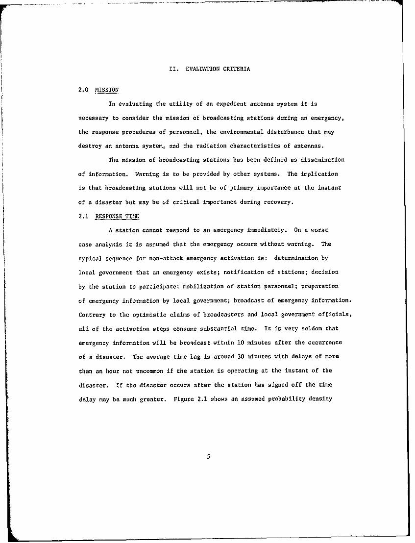
2.1 RESPONSE TIME
A station cannot respond to an emergency immediately. On a worst
case analysis it is assumed that the emergency occurs without warning. The
typical sequence for non-attack emergency activation is: determination by
local government that an emergency exists; notification of stations; decision
by the station to participate; mobilization of station personnel; preparation
of emergency information by local government; broadcast of emergency information.
Contrary to the optimistic claims of broadcasters and local government officials,
all of the activation steps consume substantial time. It is very seldom that
emergency information will be broqdcast wittiin 10 minutes after the occurrence
of a disaster. The average time lag is around 30 minutes with delays of more
than an hour not uncommon if the station is operating at the instant of the
disaster. If the disaster occurs after the station has signed off the time
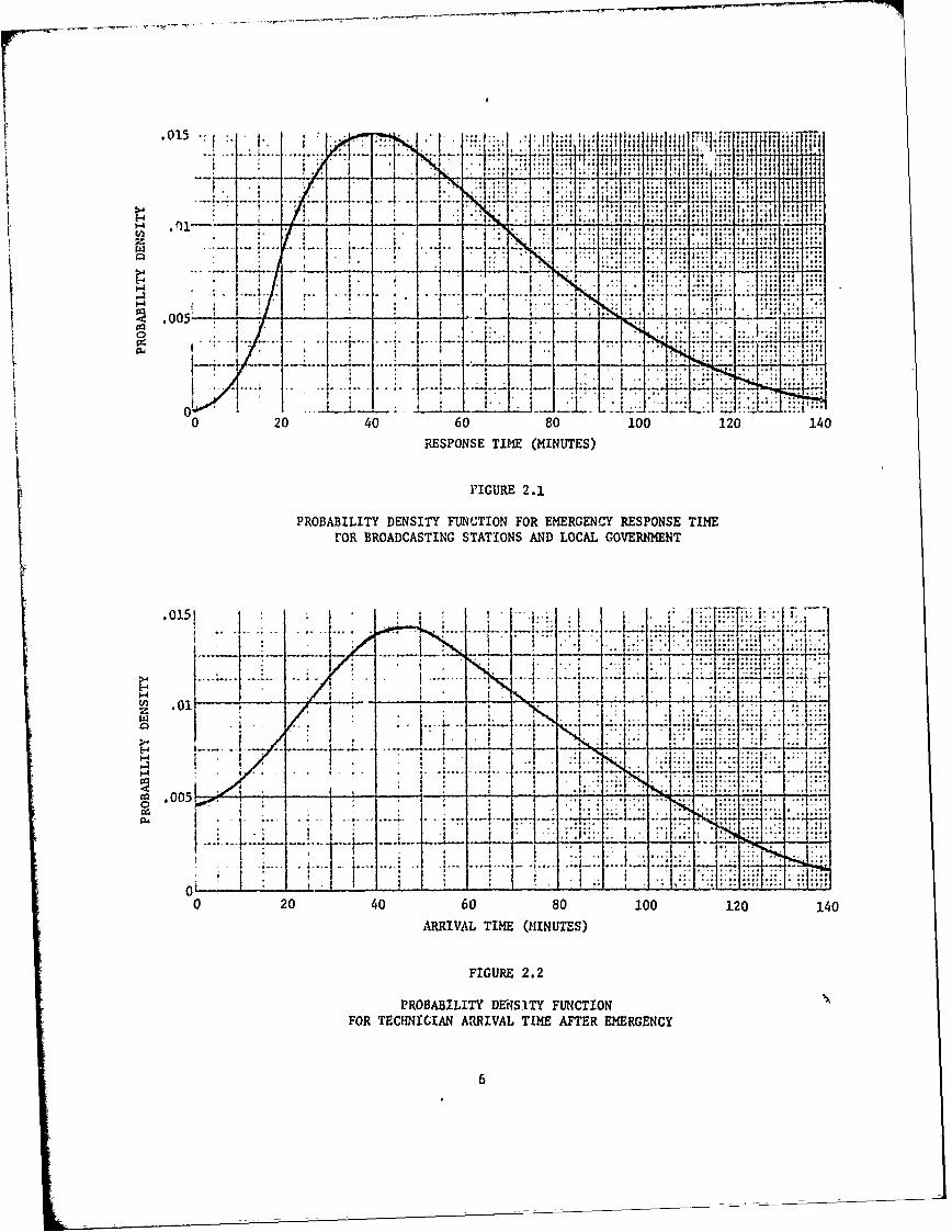
delay may be much greater. Figure 2.1 shows an assumed probability density
0-1j
020 4060 80 100 120 140
RESPONSE TIMF (MINUTES)
FIGURE 2.1
PROBABILITY DENSITY FUNC.TION FOR EMERGENCY RESPONSE TIMErOR BROADCASTING STATIONS AND LOCAL GOVERNM1ENT
.01.5!
_ .0
0
0 20 40 60 80 100 120 140ARRIVAL TIME (MINUTES)
FIGURE 2.2
PROBABILITY DENS2ITY FUNCTIONFOR TECHNICIAN ARRIVAL TIME AFTER EMERGENCY
6
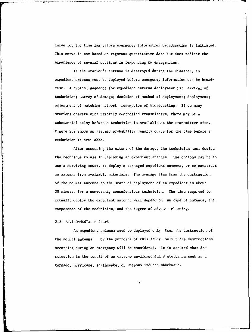
curve for the time lag before emergency information broadcasting is initiated.
This curve is not based on rigorous quantitative data but does reflect the
experience of several stations in responding to emergencies.
If the station's antenna is destroycd during the disaster, an
expedient antenna must be deployed before emergency information can be broad-
cast. A typical sequence for expedient antenna deployment is: arrival of
technician; survey of damage; decision of method of deployment; deployment;
adjustment of matching network; resumption of broadcasting. Since many
stations operate with remotely controlled transmitters, there may be a
substantial delay before a technician is available at the transmitter site.
Figure 2.2 shows an assumed probability density curve for the time before a
technician is available.
After assessing the extent of the damage, the technician must decide
the technique to use in deploying an expedient antenna. The options may be to
use a surviving tower, to deploy a packaged expedient antenna, or to construct
an antenna from available materials. The average time from the destruction
of the normal antenna to the start of deploympnt of an expedient is about
30 minutes for a competent, conscientious teamnician. The time requ~red to
actually deploy the expedient antenna will depend on he type of antenna, the
competence of the technician, and the degree of adva,,," P1 aning.
2.2 ENVIRONMENTAL EFFECTS
An expedient antenna need be deployed only fter vhe destruction of
the normal antenna. For the purposes of this study, only tin;e destructions
occurring during an emergency will be considered. It is assumed that de-
struction is the result of an extreme environmental d'sturbance such as a
tornado, hurricane, earthquake, or weapons induced shockwave.
7
While each emergency is unique, some general characteristics can
be identified. An emergency consiscs of three phases: imminent, destructive
alld recovery. During the imminent phase normal services and communications
are available. Warning information may be available and may be disseminated
by broadcasting stations and other warning systems. During the destructive
phase the environnental disturbances are coo severe to permit effective
utilization of emergency information.
The critical need for emergency information is during the recovery
phase immediately following the destructive phase. The environmental
disturbances of the destructive phase are to be expected to continlue with
decreasing severity into the recovery phase. Movement ind access to supplies
may be impaired due to destruction of roads irnd transportation facilities.
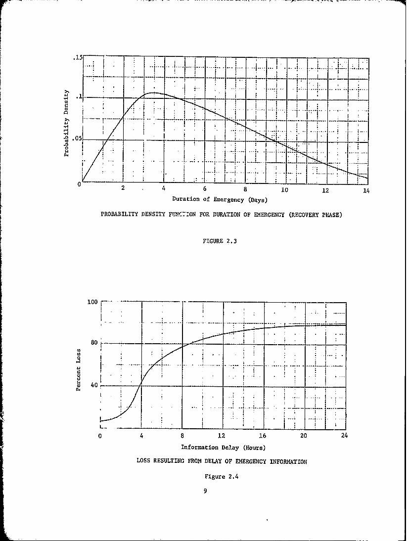
Duration of the recovery phase will be variable but will usually
be much longer than the preceding phases. figure 2.3 shows the assumed
probability density distribution for the recovery time. The recovery phase
is assumed to terminate when restrictions on supplies and movement are in-
significant.
A substantial portion of the losses during an emergency oc'cur during
the recovery phase due to isolation of individuals and uncoordinated relief
operations. Perfect communicatIons could prevent most of these losses.
Figure 2.4 shows the assumed preventable loss that would occitr if dissemination
of emergency information is delayed.
8
.15
246810 12 14Duration of Emergency (Days)
PROBABILITY DENSITY FUNCTION FOR DURATION OF EMERGENCY (RECOVERY PHASE)
FIGURE 2.3
80~
0
0 44 1 1 2 2
Information Del.ay (Hours)
LOSS RESULTING FROM DELAY OF EMERGENCY INFORMATION
Figure 2.4
9

2.3 RADIATION CHARACTERISTICS
The area in which a radio station can disseminate information is a
function of radiated power, antenna system directivity, and propogation
characteristics. Radiated power is the product of input power and antenna
efficiency. Thus, for a fixed transmitter power, reduction in efficiency is
equivalent to reduction in power. The efficlncy of a normal antenna system is
about 90%.
Directivity of an ai.renna increases the signal in some directions
and suppresses it in other directions. In AM broadcasting, a vertical antenna
has no directivity while a horizontal or a slant-wire antenna has pronounced
directivity. Directivity may be used to increase the coverage in desired
areas if the suppression can be oriented towards areas where coverage is not
necessary.
F1 antennas, except in a few special cases, are essentially non-
directional.
The most significant propagation factors for AM stations are soil
conductivity and frequency. Figure 2.5 is a tabulation of distances to the
0.5 mv/m contour for selected powers, frequencies, and soil conductivities.
The 0.5 mv/m contour is considered to render adequate service in the absence
of interference.
For an FM station the most significant propagation factor is height
of the transmitting antenna above average terrain. Figure 2.6 shows the
distance to the I mv/m contour for selected powers and heights. The FM 1 mv/m
contour is roughly the equivalent of the AM 0.5 mv/m contour in that it repre-
sents the approximate extent of FM coverage in- the absence of interference.
10
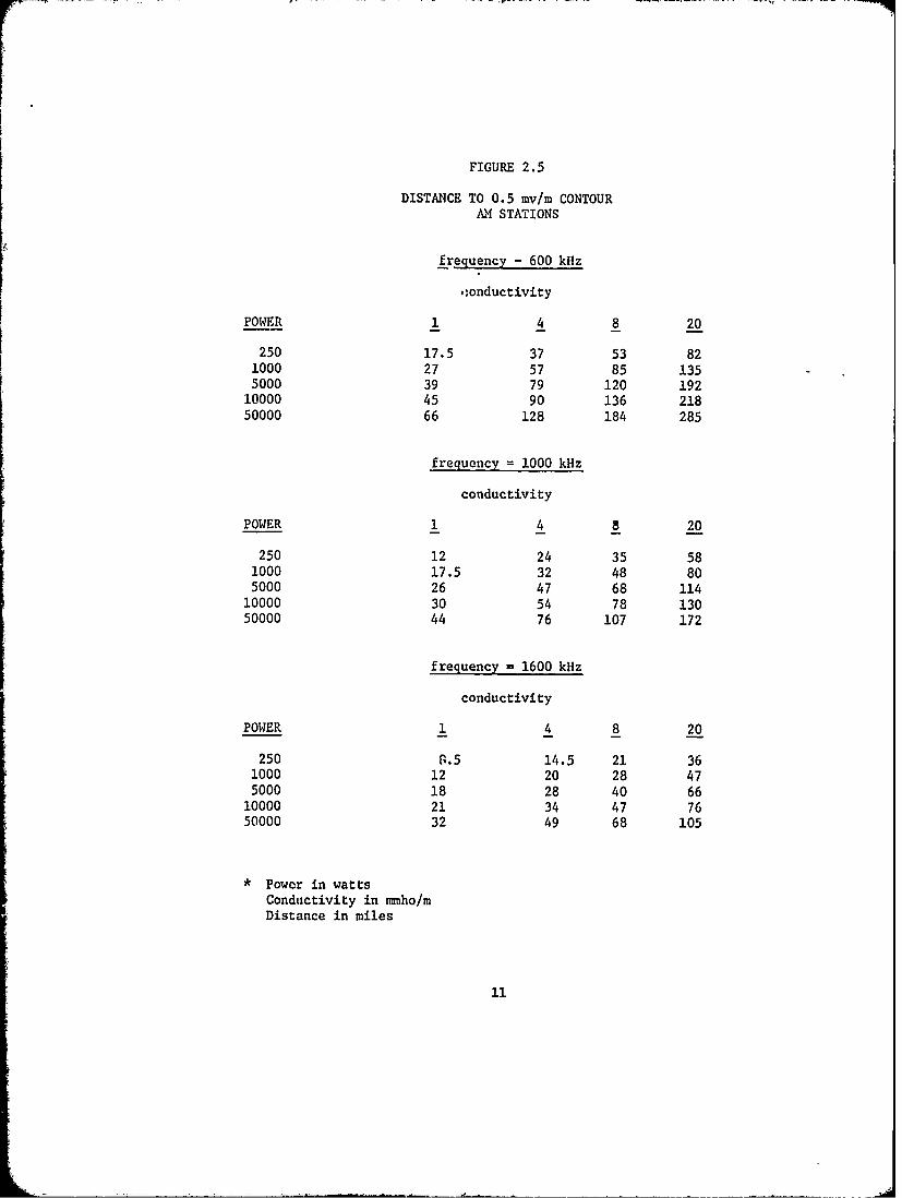
FIGURE 2.5
DISTANCE TO 0.5 mv/m CONTOURAM STATIONS
frequency - 600 kHz
:onductivity
POWER 1 4 8 20
250 17.5 37 53 821000 27 57 85 1355000 39 79 120 192
10000 45 90 136 21850000 66 128 184 285
frequency = 1000 kHz
conductivity
POWER 1 4 8 20
250 12 24 35 581000 17.5 32 48 805000 26 47 68 114
10000 30 54 78 13050000 44 76 107 172
frequency - 1600 kHz
conductivity
POWER 1 4 8 20
250 S.5 14.5 21 361000 12 20 28 475000 18 28 40 6610000 21 34 47 7650000 32 49 68 105
* Powcr in watts
Conductivity in nmmho/mDistance in miles
11

FIGURE 2.6
DISTANCE TO 1.0 mv/m CONTOURFM STATIONS
HEIGHT ABOVE AVERAGE TERRAIN
POWER 100 300 500 1000
250 5 8 10 15.5,1000 6.5 11.5 14.5 213000 8.5 15 18.5 27
10000 11.5 19 24 3350000 17 27 33 43
* Power in wattsDistance in milesHeight above average terrain in ee
12
The value function for operating at a particular power level is
difficult to assign. Obviously the highest value is to operate with emergency
facilities equivalent to the normal facilities. However, coverage at great
distances may be of lit~ie value. It is tempting to assign values based on a
standard service area such as the area within 25 miles of the station, however,
low power, high frequency AM stations in areas of low soil conductivity do not
normally provide service at distances approaching 25 miles. Also high power,
low frequency stations in areas of high soil conductivity may be located more
that 25 miles from the principal city.
13
III EVALUATION OF AM ANTENNAS
3.0 GENERAL
The expedient antenna is to be deployed by a typical stat.on
technician following the destruction of the normal antenna. Using the
expedient antenna the station is to provide service to the surrounding
communities. In order to provide adequate service the expedient antenna
must be at least a moderately effective radiator.
Any conducting object can theoretically be considered as an
antenna. However, most configrurations ie extremely inefficient. The
objective of this study is to examine the electrical and physical pro-
perties of antenna systems that a typical station technician could
deploy within a short period of time.
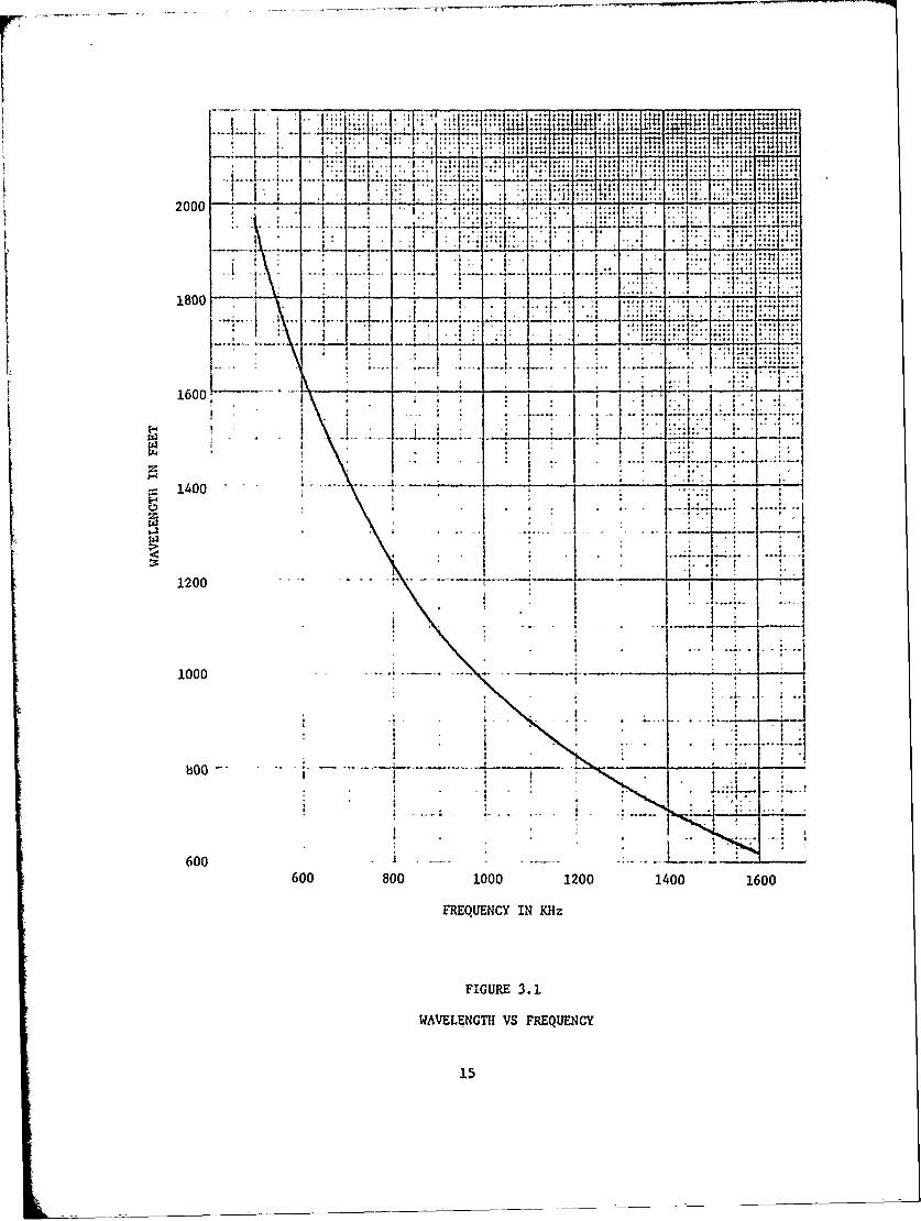
The basic unit of measurement in antenna systems is the wavelength
X. The wavelength is related to the station frequency by:
X = v/f
Where v is the velocity of propagation
f is the frequency in 11z
The velocity of propagation is approximately equal to the speed of
light.
If the frequency is expressed in MHz and the wavelength in feet -the
following relationship can be used:
X = 984/f
Figure 3.1 graphically shows the relation between frequency and wavelength.
14
N.
S_7
180 ... ..
____14)-::.
1600~
1400
1000-- ,-'---.. --- . -- - -
b . ,
600I :
600 80 00 2014010
FREQUENCY IN KHz
FIGURE 3.1
WAVELENGTH VS FREQUENCY
15
The meastrement unit can also be expressed in electrical degrees
with one wavelergth (one full cycle) equal to 3600. Thus the most com-
monly used A4 broadcast antenna may be described as a 1/4 wavelength
antenna, a 90* antenna or by the height in feet corresponding to 1/4 wave-
length at the operating frequency.
3.1 ELECTRICAL PROPERTIES
The electrical properties of interest are related to the cap-
ability of the antenna system to provide communications. These properties
are efficiency, input impedance, and radiation pattern.
3.1.1 EFFICIENCY
The efficiency of an antenna system may be expressed as the per--
centage of transmitter power that is radiate-'. Obviously a high efficiency
is de s, e, and the efficiency of a normal broadcasting antenna is
appro.... Ay 90%.
Antenna cfficiency is reduced due to power loss in the system,
principal losses being coupling component heating, ground return current
and dielectric losses.
Coupling component heating is due to current through an imperfect
inductor or capacitor. Since no component is perfect there is always
some loss, usually significant only when substantial current flows through
a large inductor. For a simple "L" network the coupling loss is
approximately:
16
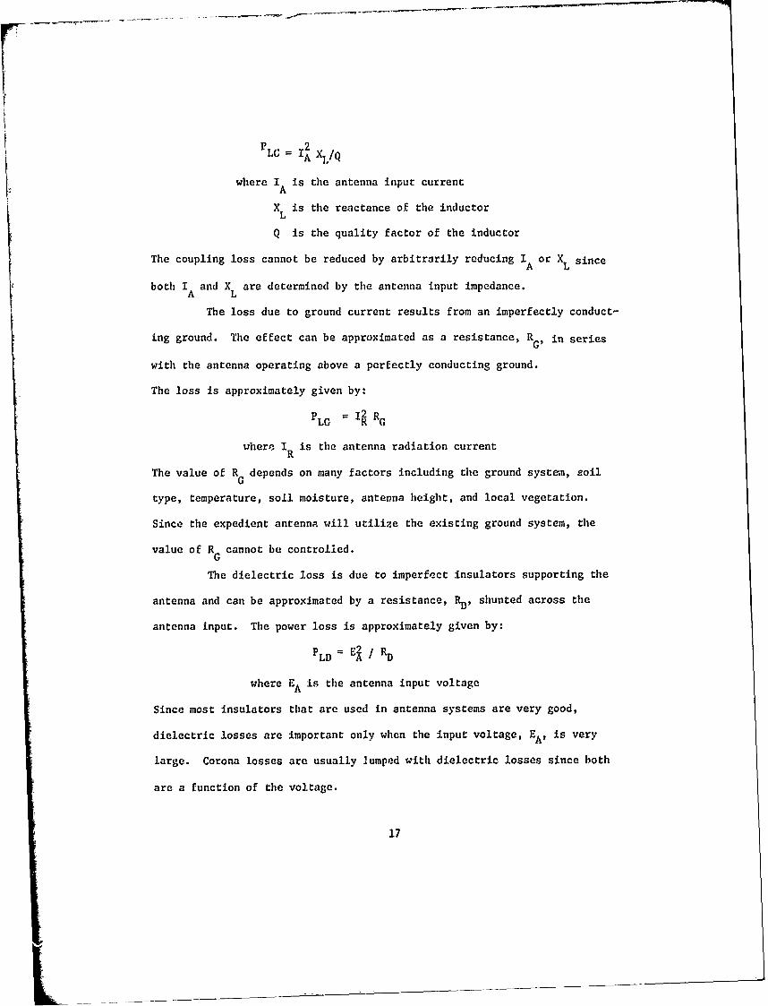
P 2LC IA k1 Q
where I is the antenna input currentA
XL is the reactance of the inductor
Q is the quality factor of the inductor
The coupling loss cannot be reduced by arbitrarily reducing IA or XL since
both IA and XL are determined by the antenna input impedance.
The loss due to ground current results from an imperfectly conduct-
ing ground. The effect can be approximated as a resistance, RG, in series
with the antenna operating above a perfectly conducting ground.
The loss is approximately given by:
PLG I RG
where IR is the antenna radiation current
The value of RG depends on many factors including the ground systam, soil
type, temperature, soil moisture, antenna height, and local vegetation.
Since the expedient antenna will utilize the existing ground system, the
value of RG cannot be controlled.
The dielectric loss is due to imperfect insulators supporting the
antenna and can be approximated by a resistance, R, shunted across the
antenna input. The power loss is approximately given by:
PLD = E / RD
where EA is the antenna input voltage
Since most insulators that are used in antenna systems are very good,
dielectric losses are important only when the input voltage, EA, is very
large. Corona losses are usually lumped with dielectric losses since both
are a function of the voltage.
17
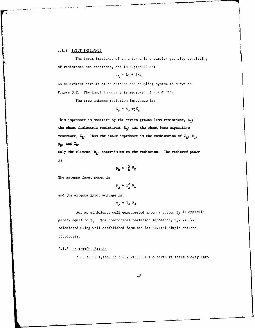
3.1. INPUT IMPEDANCE
The input impedance of an antenna is a complex quantity consisting
of resistance and reactance, and is expressed as:
ZA = RA 4 iXA
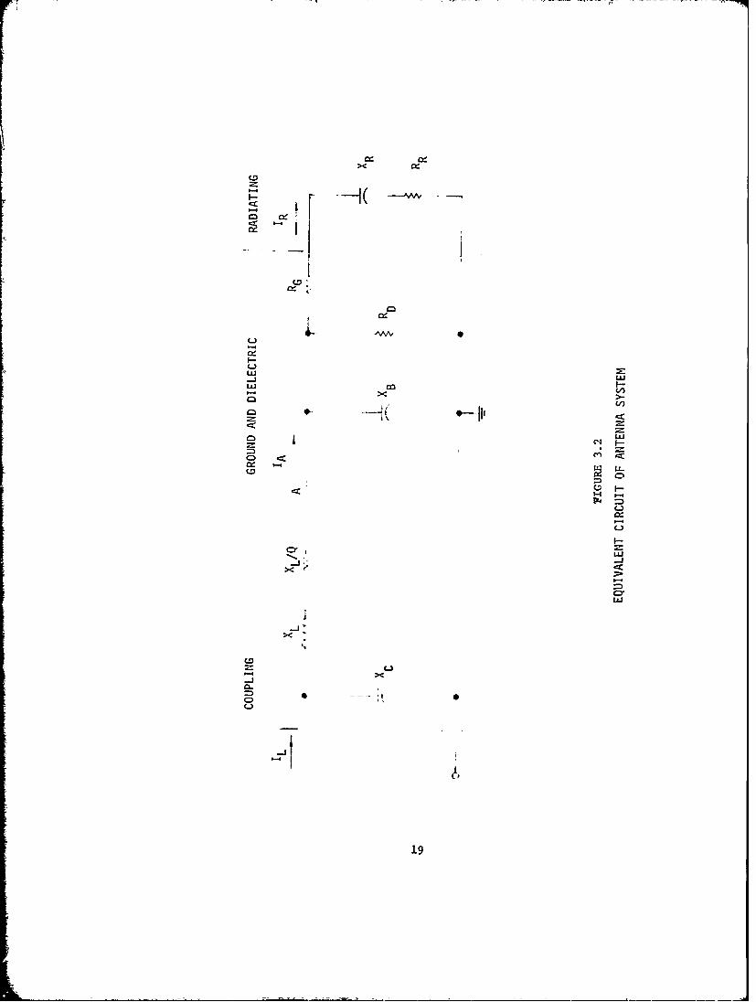
An equivalent circuit of an antenna and coupi±ng system is shown cn
Figure 3.2. The input impedance is measured at point "A".
The true antenna radiation impedance is:
ZR = RR +iXR
This impedance is modified by the series ground loss resistance, RG
the shunt dielectric resistance, RD; and the shunt base capacitive
reactance, XB. Thus the iniut impedance is the combination of ZR, R ,
RD, and XB.
Only the element, RR, contribuses -to the radiation. The radiated power
is:
The antenna input power is:
PA = I2 RA
~A A~R
and the antenna input voltage is:
VA = IA ZA
For an efficient, well constructed antenna system ZA is approxi-
mately equal to ZR. The theoretical radiation impedance, ZR, can be
calculated using well established formulas for several simple antenna
structures.
3.1.3 RADIATION PATTERN
An antenna system at the surface of the earth radiates energy into
18
,----~~------ ------. ,--- - U ,- - -
CD
-4-
LILiLi
C) <
o D' LLi
* -
1-4-
C-)
CD-
CLi
~~19
the entire hemi phere above -the surface. The distribution of the radiated
energy within the hemisphere is known as the radiation pattern. Only
energy radiated in the horizontal plane can be received within about 50
miles of the transmitter, and energy radiated above the horizon is
effectively lost.
The radiation pattern is a function of current distribution in
the antenna system. Current distribution is determined by the physical
configuration and the interaction between elements of the antenna
system. An image of any radiator above a conducting ground is reflected
in the ground system and this image must be considered as an element of
the antenna system. For most antenna systems current distribution and,
hence the radiation pattern is deternined entirely by the configuration.
The complexity of special antennas with modified current d±=cributions
preclude their use as expedient antennas.
The maximum radiation from a straight, uniform conductor is
perpendicular, or broadside to the conductor. Radiation off the end of
the conductor approaches zero. Thus a vertical radiator has a maximum in
the horizontal plane and has a non-directional azimuth pattern.
A horizontal radiator near a conducting ground has two deep minima
off the end, Due I.o the image element the maximum, radiation is vertical
and radiation in the horizontal plane is reduced.
3.1.4 ANTENNA TYPES
Many different configurations of conductors can be used as
antennas with each configuration possessing unique electrical characteristics.
For an expedient antenna only relatively simple configurations that can be
20
deployed in a short time by one techniciait are practical.
These antennas can be categorized as vertical monopole, non-
vertical monopole, top-loaded, and folded unipole.
3.1.4.1 VERTICAL MONOPOLE ANTENNA
The vertical monopole is the most commonly used antenna for AM
broadcasting. The radiating structure is a single vertical conductor
over a conducting ground system. The theory of the vertical mrnopole
antenna is well developed. Current distribution is approximately
sinusoidal.
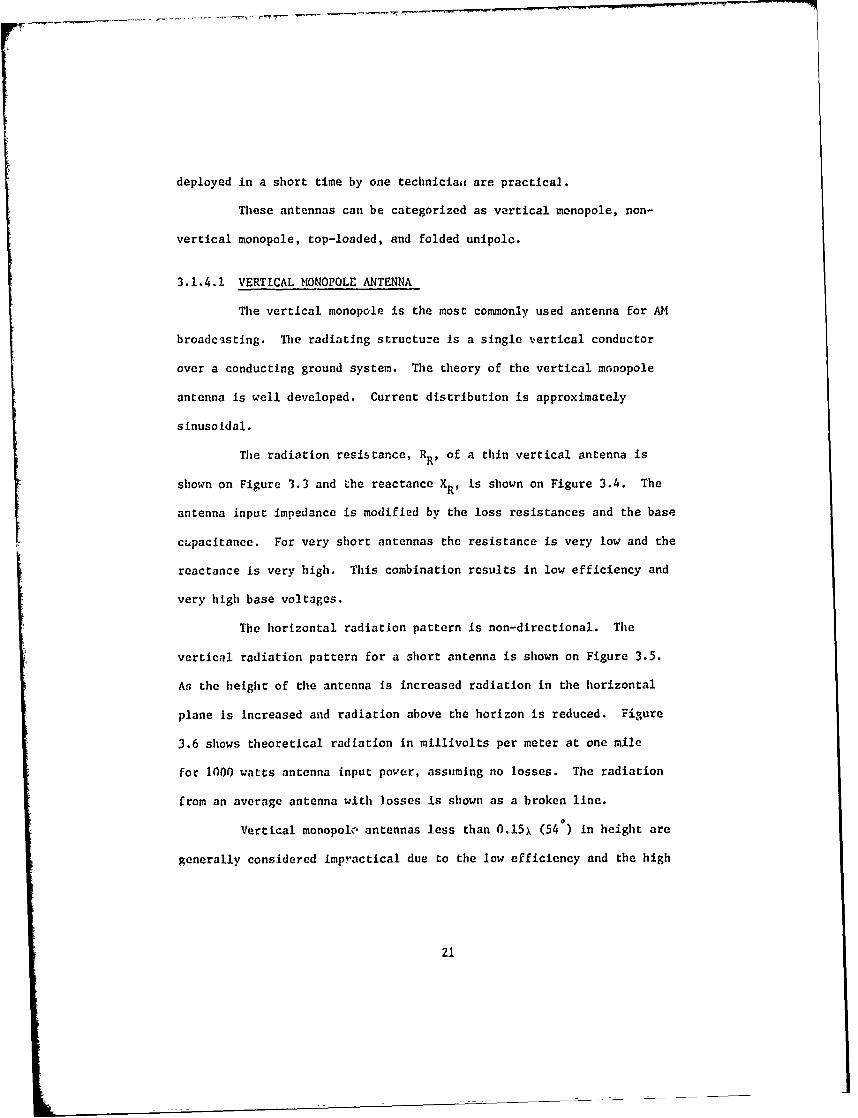
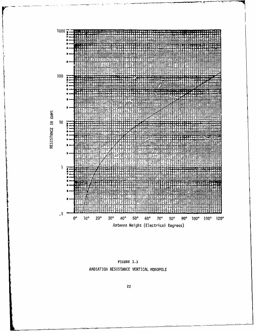
The radiation resistance, RR, of a thin vertical antenna is
shown on Figure 3.3 and the reactance XR, is shown on Figure 3.4. The
antenna input impedance is modified by the loss resistances and the base
c~pacitance. For very short antennas the resistance is very low and the
reactance is very high. This combination results in low efficiency and
very high base voltages.
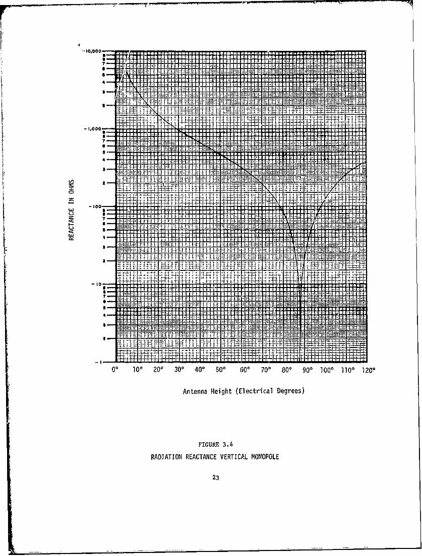
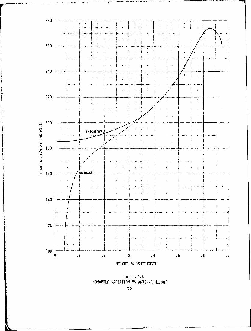
The horizontal radiation pattern is non-directional. The
vertical radiation pattern for a short antenna is shown on Figure 3.5.
As the height of the antenna Is increased radiation in the horizontal
plane is increased and radiation above the horizon is reduced. Figure
3.6 shows theoretical radiation in millivolts per meter at one mile
for 1000 watts antenna input po.'er, assuming no losses. The radiation
from an average antenna with losses is shown as a broken line.
Vertical monopolx, antennas less than 0.15x (54 ) in height are
generally considered Impractical due to the low efficiency and the high
21
1000
V A !-IA-I I- :1: . tT =I--i- -in z zz z z z z_=w7nn=nnn=t=:=A44- z z
'MIT k T
ME z n; z
14 Z Z
1-:w- 7 HF: :I:t VJ.4-;wm
100 N
zl -FF"_ 14--V -4-14-PJ P zj_- nn
AF E
nj 4- -1
Ff", ffl P MT
10 1-1-1 1 1 1 1 1-,T-F I T- I I I I IA" Ynt 4 T I111- 1 1111 IF 1-1 4 1, - -T - - I V J. -1 f 1 1-1. --f:
-1 I-t7i- .1 1 -1 1-1 1 1 1 4-L&J -1 t 4 !4 F 1 44-L3 ni 51=
A!-1-17 -1 k-1:1 A. ff
V) -FIA4 I- _FLf) 77 Ty z z_
TTHTL ft TIL WCX TA.
44-41-
44-1 1 i +
__vr7TFT VIA 1-IlA i-I It- -1-1 I-VIA-44=11-111-1
+11 J- Az A t t44- zjrj -1 rA U t _T M
IV 1, -1 1, 147- _144
--- ----- ---IT _ = =
TIT
06 ML a-Liz"
0* 100 200 300 400 500 600 700 800 900 1000 1100 1210
Antenna Height (Electrical Degrees)
FIGURr 3.3
RADIA:rION RESISTANCE VERTICAL MONOPOLE
22
-10,000 f I I I -F"v I I-T- -------
I I-f I I 1 1-1 1 1 1-1- A . 1.2-
4 7-
1A -F 1z -+ffff tit j :!u t mam
T
R 4:-1,000 I FTIT-I IT 1 -111 4-i f f F ------------
--- --3,1 1 1 1
41- -4-- --t5A -H.- t-= -F
7-'r, I, .. -1:ff 1zTZ2 H
-4T
+la
-100LLS I- A 1.1 1 1 t F - I 1 1, 1 VI F-I I
-1 1 1 14 V J
A I f I I t -1-1-1 ......LLJ -1 1-11 1 1- - 1-1 1 f- I + I F F -H - I I I 1- .1 4, D. -I-#- - -
AA4- 4--P 4--VI
A I T
=t: 4
-10[Lull
70 I-A ---- - -
-Km IF
4 1- 4, -1 1 f 1 1 I- I- - - A-I I- [.I- ji i-1,4 -1- -1-1 1-1,1- 1 44- A- I - - -
-7 ---14 VJf:Tr
AJiH
'Irv,
00 100 200 300 400 500 6 0 700 800 900 1000 1100 1200
Antenna Height (Electrical Degrees)
FIGURE 3.4
RADIATION REACTANCE VERTICAL MONOPOLE
23
900 s* 70' 600 so* 409*
00
4-
10i
0 0.2 0.4- 0.6 0.8 1.0[ RELATIVE FIELD
FIGURE 3.5
VERTICAL RADIATION PATTERNSHORT MONOPOLE ANTENNA
24
280 -.
C - -. I_ ; I
260 - - - -.
I-
240
220 ' -
20 . ,
.: THWE -,ICAt
0< 180 ... _____ I . _ .-- -_
>V
-'160AVAi
,II i. . t
II *
140 "'- -
12o0 --I
0 .1 .2 .3 .4 .5 .6 .7
HEIGHT IN WAVELENGTH
FIGURE 3.6MONOPOLE RADIATION VS ANTENNA HEIGHT
25
Input voltage. As an expedient antenna the very short vertical monopole
with low resistance and high reactance would probably exceed in difficulty
the capability of the station technician to achieve an appropriate trans-
mitter-antenna match.
3.1.4.2 NON-VERTICAL MONOPOLE ANTENNAS
If a monopole antenna is oriented other than vertically above
the ground system the characteristics are changed. Common types of non-
vertical antennas are the slant wire, horizontal wire, inverted "L", and
bent wire. While these are slightly different in configuration, per-
formance characteristics are essentially identical. The names derive from
the initial uses of the antenna systems.
Any monopole antenna can be characterized by its total length and
average slope. When the slope is 900 the antenna is a vertical monopole
and when the slope approaches 0 it is a horizontal wire antenna.
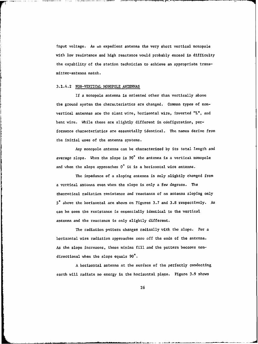
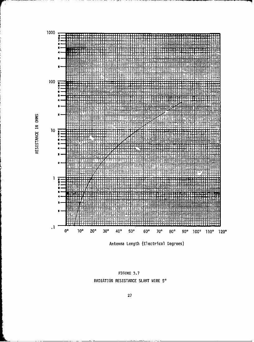
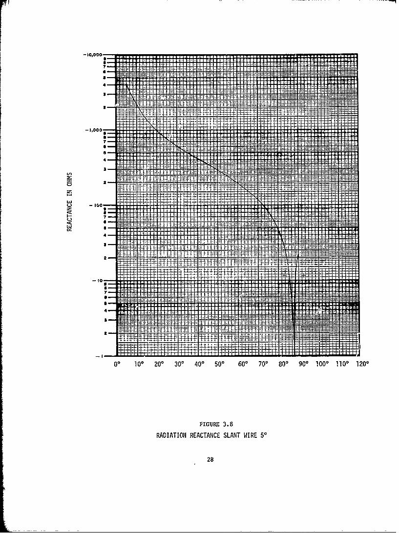
The impedance of a sloping antenna is only slightly changed from
a vertical antenna even when the slope is only a -few degrees. The
theoretical radiation resistance and reactance of an antenna sloping only
50 above the horizontal are shown on Figures 3.7 and 3.8 respectively. As
can be seen the resistance is essentially identical to the vertical
antenna and the reactance is only slightly different.
The radiation pattern changes radically with the slope. For a
horizontal wire radiation approaches zero off the ends of the antenna.
As the slope increases, these minima fill and the pattern becomes non-
directional when the slope equals 900.
A horizontal antenna at the surface of the perfectly conducting
earth will radiate no energy in the horizontal plane. Figure 3.9 shows
26
1000-1 .1 1 VI I I I UP
J-1-1- 4-
14-1-MAM 4
4-1- j-,
P MITI :::=r;E- ZRTT: 7 R;_ -TE T M I
T -.-H TF TRIIT A T- 77T -11-
-H4100
A-14-444- 4+0 14-t 41-F
M tf i t If -1-4
7- AAAA-744z A_ - -14- -11-144-11- 4- -+ -T MR
-Uk -1-4 iff, I s T
T-t A
C) t-Hi+
+
LU 10 I _f_ F A, I_ i-1--14 -
Hj
V)U.] 4=1- -1, A-V -t :14 'HA0: T1T.- += =i _.
9 _ T_
r: 3--
"H-Hi 4ftt i4l- - -1 _t
1--u 4 1-1- IA If I .1 1 14.
-1-t- t- 4- -A- -4444- -A Ar .1447 zhr - t4 A V 4 Vib=
4=4 ov.L:
----------- -IKEEIT
00 100 200 300 400 500 600 700 800 900 1000 1100 1200
Antenna Length (Electrical Degrees)
FIGURE 3.7
RADIATION RESISTANCE SLANT WIRE 50
27
-1080001-1 I-L Ir A- 1 -1 1 V 4-144A4- -1 4A - - - - -
7
-ft
4 L k-T- 41 A 1M
RM
T ------ 44m -t THAT If -:A E
ttiftit
-1,000 444- T-pl- I I I I A J- A -I- a:
0 1: zF --- --------rT= z
Ett-4 -=Z=z
A 1: A 4 1 1-1 14 t.t "k zP -1 r
3 ------V) --M1 -T _- r
+21 _H4+ -w 44-1-u 1100- @-t fit -,t"., -11 11< U- VIA -11-
Z.L.L - zi I7
.4
LLJ A- J-17- 1- -14:1 1-. 1. -JAA -1 -- --1-1 t -f,1 f-A- f 1. 4- -1-- -I I A- 4- r1-f-f-1= -1 -
-3 -M
A ttl: z:Fr Z :Z L.' Z rz.;= 1
Tsff:f TTT f 7 r-: t2 i
414-1 -111 1 A- -1 IT
0 -144- 44z
TTFM loll --jL- L U -4
J7
4-' T
11 f I I i
00 100 200 300 400 500 600 700 800 900 11000 1100 1200
FIGURE 3.8
RADIATION REACTANCE SLANT WIRE 50
28
70 80 90 80 7
60 60
50 50
~4 U
40 4
30 cu30
Ar,0 0
1.0 0.8 0.6 0o.. 0.2 0 0.2 0.4 0.6 0.8 1.0
RELATIVE FIELD
FIGURE 3.9
VERTICAL RADIATION PATTERNHORIZONTAL WIRE ANTENNA
29
' .. . .2T 2--,, ,,. ,-, - -- 5 , ,;,.. ,G ,, ,... .,, .. ,. ,,,,., .,, l . -,, .,,,. . . ; • . ,, ,,,; -- ,---,4-
. ........ .. T- - t-
-- - -w k r- -ro .... - - . "I. --- h --- . .
:. I *1 *
II, I
70 %9 4 A9- 1
. APPARE'F EN URN ' : E .i
RLAIVE RBTIO
1 4 G. E 40.-I.
30O
III APPARENTE-4 '-IT Hrriot STR I99I L
I-IN
FIGUR 3.J.0
CURN ISRBTO O O-ODE NEN
* *30
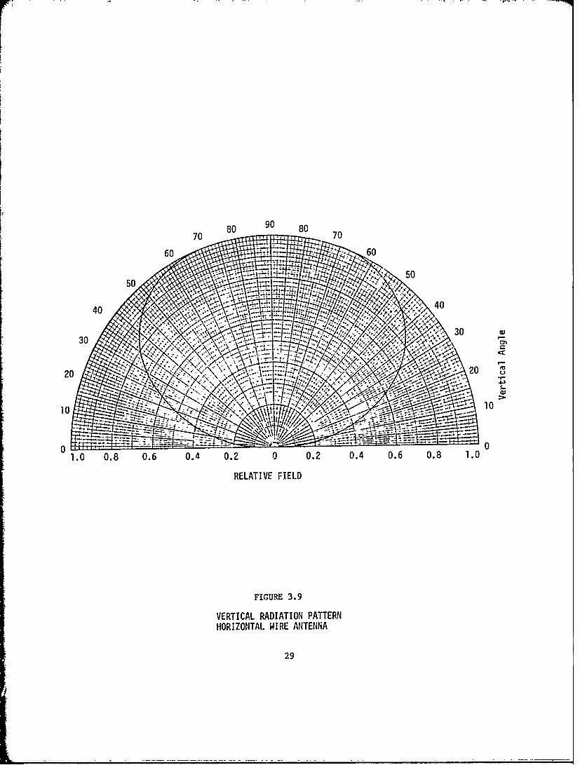
the theoretical vertical radiation pattern of a horizontal wire on the
surface of a perfect conductor. Since the earth is not a perfect conductor
there will be some radiation broadside to the antenna. As the height of
the antenna above ground or the slope is increased, the radiation in the
horizontal plane increases and the vertical pattern approaches the vertical
monopole pattern as the slope approaches 900.
An antenna with a near horizontal slope is a very ineffective
radiator for local reception. However, it is one of the easiest to deploy
and use to provide limited temporary coverage.
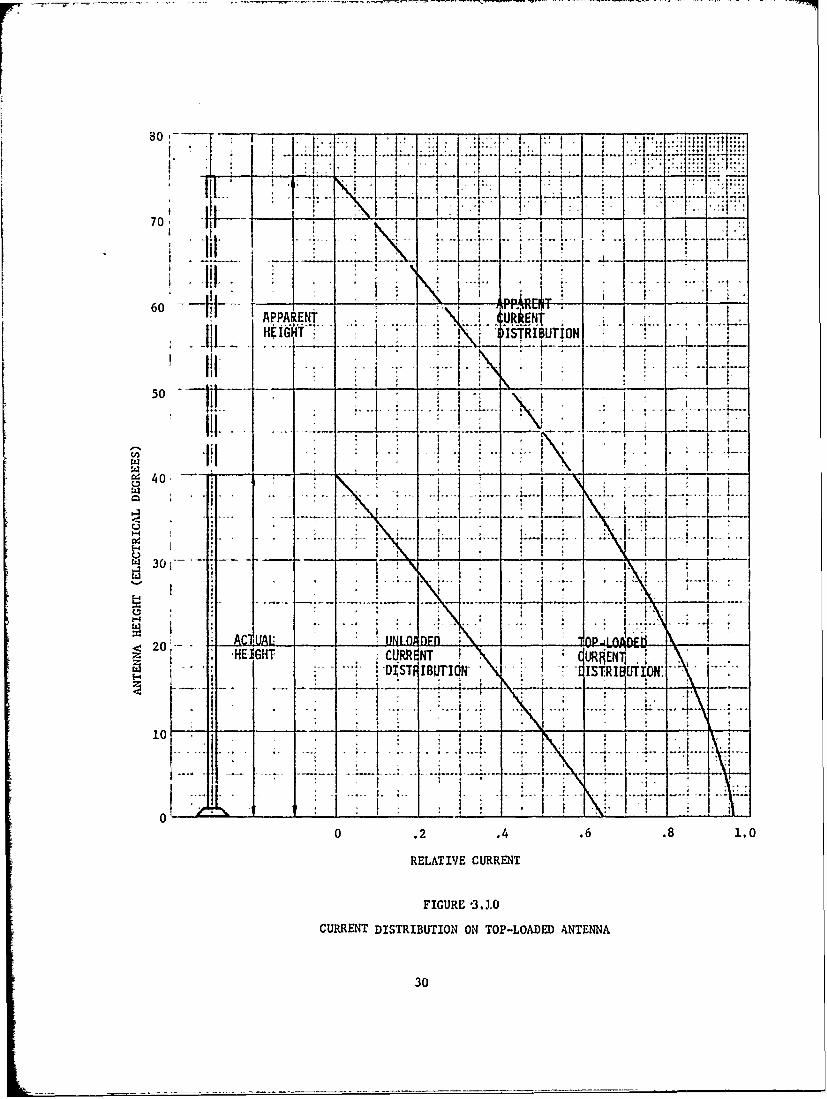
3.1.4.3 TOP-LOADED ANTENNAS
The current distribution of a short antenna can be modified by
adding capacitance to the free end. The modif.ed current distribution
approximates the sinusoidal distribution of a taller radiator. Figure
3.10 is a sketch of a top-loaded antenna showing the current distribution.
Since the current distribution determines the antenna impedance,
the input impedance of a top-loaded antenna is approximately equal to the
impedance of an unloaded antenna with a physical length equal to the
apparent length of the top-loaded antenna. In the horizontal plane the
radiation pattern is essentially identical to the pattern of an unloaded
antenna. Due to radiation from the top-load, the vertical pattern may be
different.
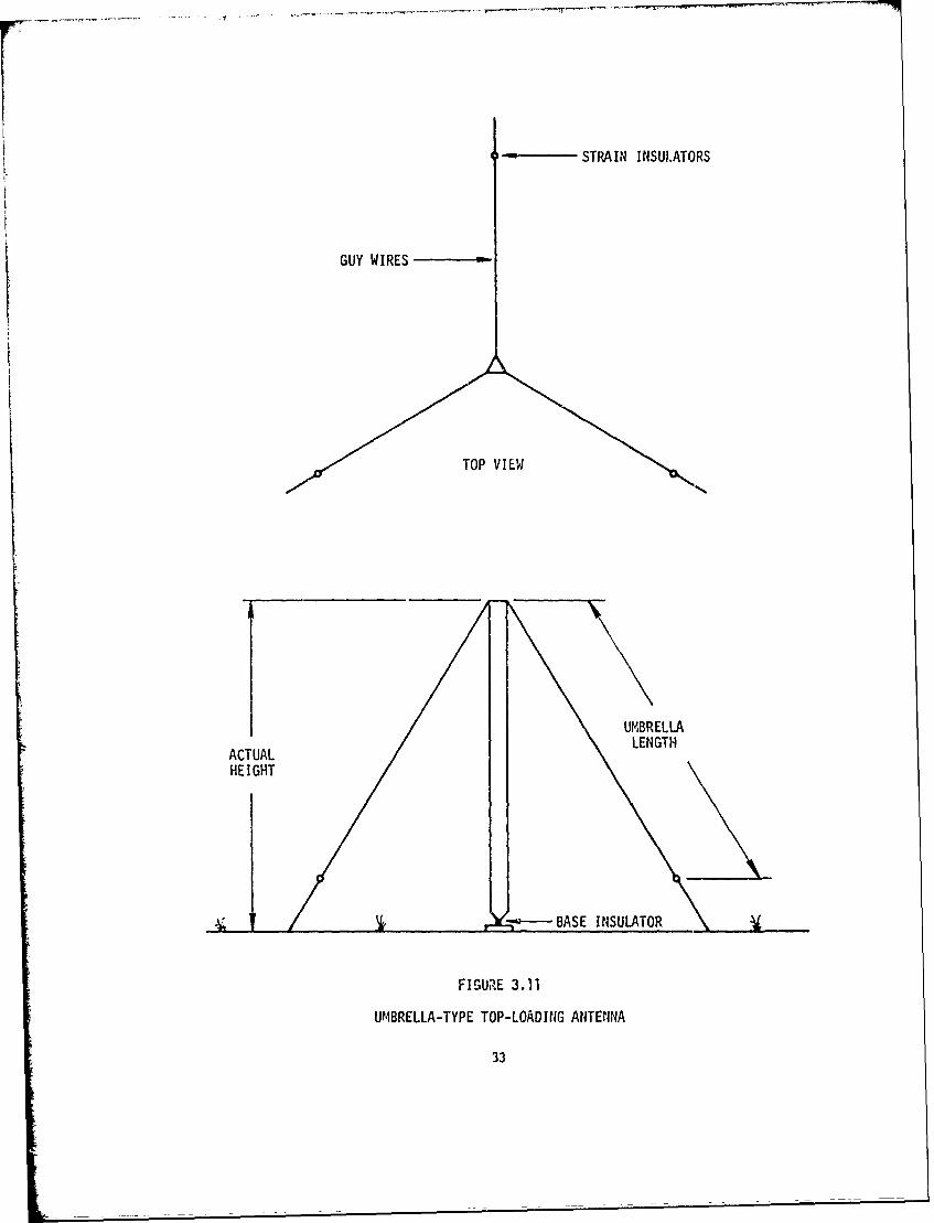
Many configurations have been developed to create the top-
loading capacitance. Some of the types are: flat-top, top-hat, "T",
spiral, skirt, and umbrella. Construction difficulties preclude the use
of all except the "T" and umbrella as expedient antennas. The umbrella
is both more effective and easier to deploy than the "T" antenna.
31

A sketch of a top-loaded antenna using three umbrella wires is
shown on Figure 3.11. The apparent antenna length is approximately
equal to the vertical length plus the umbrella length. If the umbrella
length is greater than about one half the vertical height, the apparent
anvenna length is less than the sum of the height and the umbrella length.
The apparent length can be increased slightly by adding more umbrella wires,
symmetrically around the vertical radiator.
As the length of the umbrella wires is increased the vertical
radiation increases. This reduces the horizontal radiation, however, the
reduction is offset by an increase in efficiency due to higher input
resistance. The optimum length for the umbrella appears to be approxi-
mately the height of the vertical radiator.
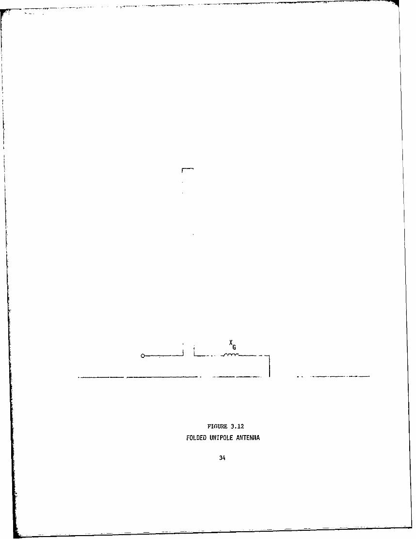
3.1.4.4 FOLDED UNIPOLE ANTENNA
A folded unipole antenna consists of two or more closely spaced
parallel conductors. The upper ends of the conductors are connected. One
conductor is used as an input and the other is grounded, sometimes through
a reactance. A sketch of a folded unipole is shown on Figure 3.12.
The unipole cot.figuration acts as a transformer and can be used to
increase the input impedance. The transformation ratio is a function of
the configuration and the reactance XG .
The most common foldea unipole configuration is equal diameter
conductors one quarter wavelength long. The reactance XG is not used and
the transformation increases the input resistance by a factor of 4. Since
the reactance of a resonant quarter wavelength antenna is zero the input
reactance is zero.
32
41 - STRAIN INSULATORS
GUY WIRES
~TOP VIEW
UMBRELLALENGTHACTUAL GNTHEIGHT
B~---ASE INSULATOR
FIGURE 3.11
UMBRELLA-TYPE TOP-LOADING ANTENNA
33
r - -'- -,..----,, - "--,-
xG
FIGURE 3.12
FOLDED UNIPOLE ANTENNA
34
For a short antenna the transformation is complex. For heights
less than about 500 it is necessary to use the reactance XG to increase the
input resistance. By controlling the value of X it is possible to achieve
any input resistance up to several thousand ohms.
The radiation pattern of a folded unipole is essentially identical
to the pattern of a short monopole. If XG is adjusted to produce a high
input resistance the efficiency can be very high.
The adjustment of X. is critical. Successful adj'isr.ment requires
the use of an impedance bridge. Since most stations do not have an
impedance bridge, it would probably not be possible to deploy the folded
unipole as an expedient antenna in most situations.
3.2 PiYQICAL PROPERTIES
Anv antenna system is a conducting physical structure. The
ability to rapidly fabricate or deploy the physical structure necessary
for an antenna system limits the types of feasible expedient .ntennas.
A rigid steel tower is used as an antenna by essentially all radio
stations. The tower may be either guyed or self-supporting. Top-loaded
antennas normally use a rigid tower as the principal radiator and umbrella
wires for the top-loading. It is not possible for a technician to erect
an equivalent tower for an expedient antenna under emergency conditions.
The easiest and fastest expedient antenna to deploy -Es the hori-
zontal or slant wire. The antenna properly insulated can he supported
by posts, trees, buildings, or any other natural or man-made structure. The
higher the antenna is supported above ground the more effective it will be.
If a wire is to be used as an antenna, consideration must be given
to current carrying capacity. A #10 gauge wire is rated at 35 amperes
35
Thus, for a power of 1000 watts, the antenna input resistance must be
greater than I ohm. For 10,000 watts the resistance must be at least
10 ohms. These minimum resistances correspond to minimum lengths of about
200 and 600 for 1000 watts and 10,000 watts respectively. For shorter
antenna lengths, larger wire must be used.
One method of achieving a vertical antenna is to suspend a wire
from a balloon. The wire length can be cut to one quarter wavelength or
greater if desired. However, if a 10 foot diameter helium filled balloon
is used the maximum weight must be less than 23 pounds. Copper wire, size
610, weighs about 31 pounds per thousand feet. Thus a quarter wavelength
antenna at 540 kHz would weigh about 15 pounds.
The 10 foot balloon would support the antenna under zero wind
velocity conditions. With a 30 mph wind, drag on the balloon would be
140 pounds and the average slope of the wire would be less than 100. In
slightly gusting wind, portions of the antenna would probably contact the
ground and short out the antenna. At least a 50 foot diameter balloon
would be required to have a reasonable assurance of maintaining a usable
antenna. An additional tether cable would be required to anchor the
balloon since the tensile strength of #10 copper wire is only about 540
pounds. Even ignoring the problems of storing the balloon and helium it
is doubtful that one man could deploy a. 50 foot balloon.
Light weight towers such as are used to support television receiv
ing antennas =an be erected in a few hours by two men. The maximum height
is about 70 feet. If such a tower were top-loaded, it could form a useable
antenna system for frequencies above 1200 kHz.
36
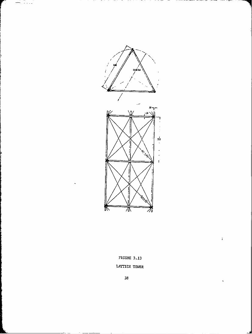
A number of cuick erect towers have been developed, and one of
these, a lattice tower, is shown on Figure 3.13. According to the manu-
facturer, two men can erect a 100 foot tower in about one hour. lowever,
the cost of about $7,000 for 100 feet may be prohibitive in the DCPA
application. A height of at least 150 feet would be required for a top-
loaded tower at 540 kllz.
3.3 RECOMNENDATIONS
Time is probably the most important consideration in restoring
communications, and the expedient antenna to be deployed should be as
simple as possible in order to save construction time.
Approxrmately 25 percent of A.! broadcasting stations use a direct-
ional antenna system consisting of two or more towers. If there is a
surviving tower, then this tower is recommended for use as an expedient
zntenna. If there are no surviving towers, the antenna fastest to deploy
is the horizontal wire. Unfortunately, it is also the least effective. A
top-loaded vertical antenna has reasonable effectiveness but requires
substantial time to deploy. A two step deployment is therefore the recom-
mended strategy. A horizontal wire should be deployed for immediate
limited service and, (while using the horizontal wire in the interim ), a
top-loaded antenna should be constructed at key stations. This should
permit restoration of limited communications within 30 minutes and
effective cornunications at critical points within 8 hours.
37
/L\\ Du \
:S/
FIGURE 3.13
LATTICE TOWER
38
IV. AM FEEDER SYSTEMS
4.0 GENERAL
Most antenna systems require an impedance matching network to
couple from the transmission line to the antenna. The network usually
conqists of lumped inductance and capacitance in the form of L, T. or v
sections. If the antenna input is not a pure resistance, it can be
made to look like a pure resistance by adding a reactance element in
series that will make the antenna series resonant. This is usually done
to simplify the network design.
The antenna input impedance is:
Za = Ra + jXa
where Ra is the resistive component
Xa is the reactive component
If a series reactance (Xs) is added such that Xs = -Xa
the input is resonant and the coupling problem reduces to matching a pure
resistance (Zo, the transmission line impedance) to a pure resistance (Ra).
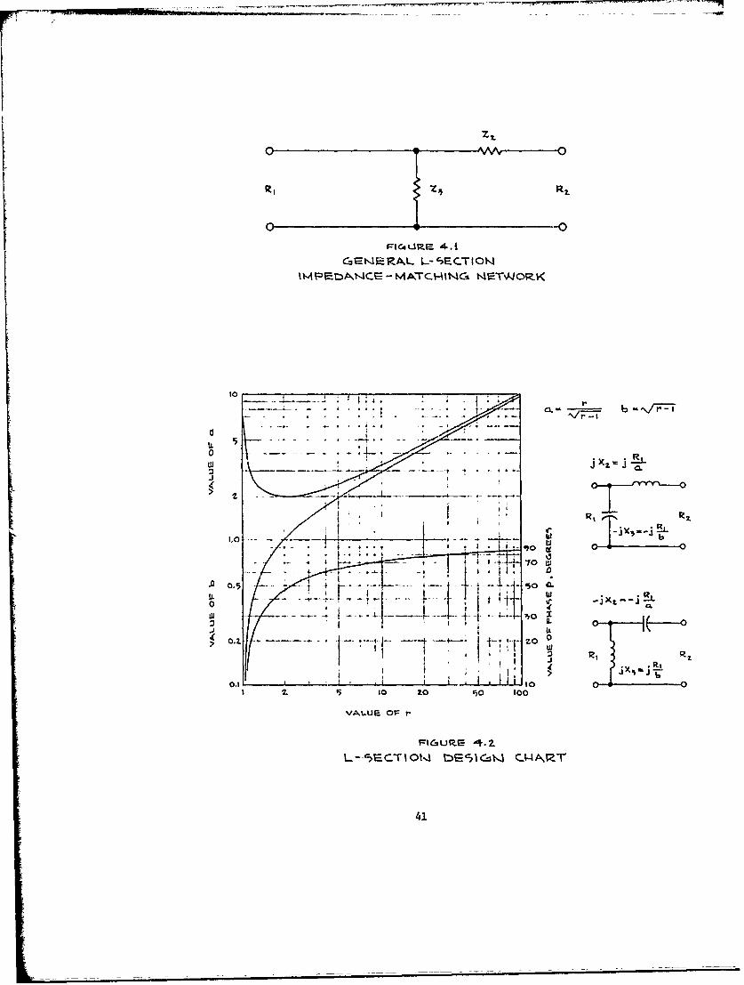
4.1 L SECTIONS
An L section consisting of an inductor and a capacitor is the
simplest match between pure resistances. Figure 4.1 is a sketch of a basic
L section. The larger terminating resistance is designated as R1 and the
transformation ratio is defined as r = RI/R 2
For most expedient antennas the characteristic impedance (Zo) of the trans-
mission line will be greater -than the antenna input resistance (Ra). Thus,
can be identified as Zo and R2 as Ra. In the case of a tall or long
antenna where Ra is greater than Zo the relationship is reversed.
39
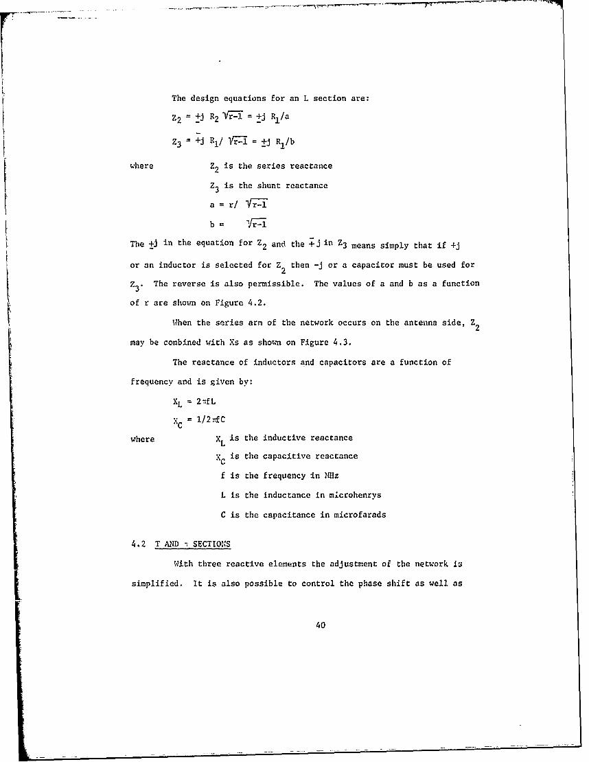
The design equations for an L section are:
Z2 = +j R2 Vr--l = +j Rl/a
Z3 +j RI/ YVI= ±j Rl/b
where Z2 is the series reactance
Z3 is the shunt reactance
a = r/ fr-1
b = VrI--
The +J in the equation for Z2 and the +j in Z3 means simply that if +j
or an inductor is selected for Z2 then -j or a capacitor must be used for
z3 . The reverse is also permissible. The values of a and b as a function
of r are shown on Figure 4.2.
When the series arm of the network occurs on the antenna side, Z2
may be combined with Xs as shown on Figure 4.3.
The reactance of inductors and capacitors are a function of
frequency and is given by:
XL = 2ifL
XC = l/2-fC
where XL is the inductive reactance
X is the capacitive reactance
f is the frequency in Mz
L is the inductance in m.crohenrys
C is the capacitance in microfarads
4.2 T AND - SECTIONS
With three reactive elements the adjustment of the network Is
simplified. It is also possible to control the phase shift as well as
40
L 10Co
3 CL
0) 71.i0H ..
IL 0
I 2. 5 10 ~ O '0 10If1.U OA to
>l~U~ 4.
41,
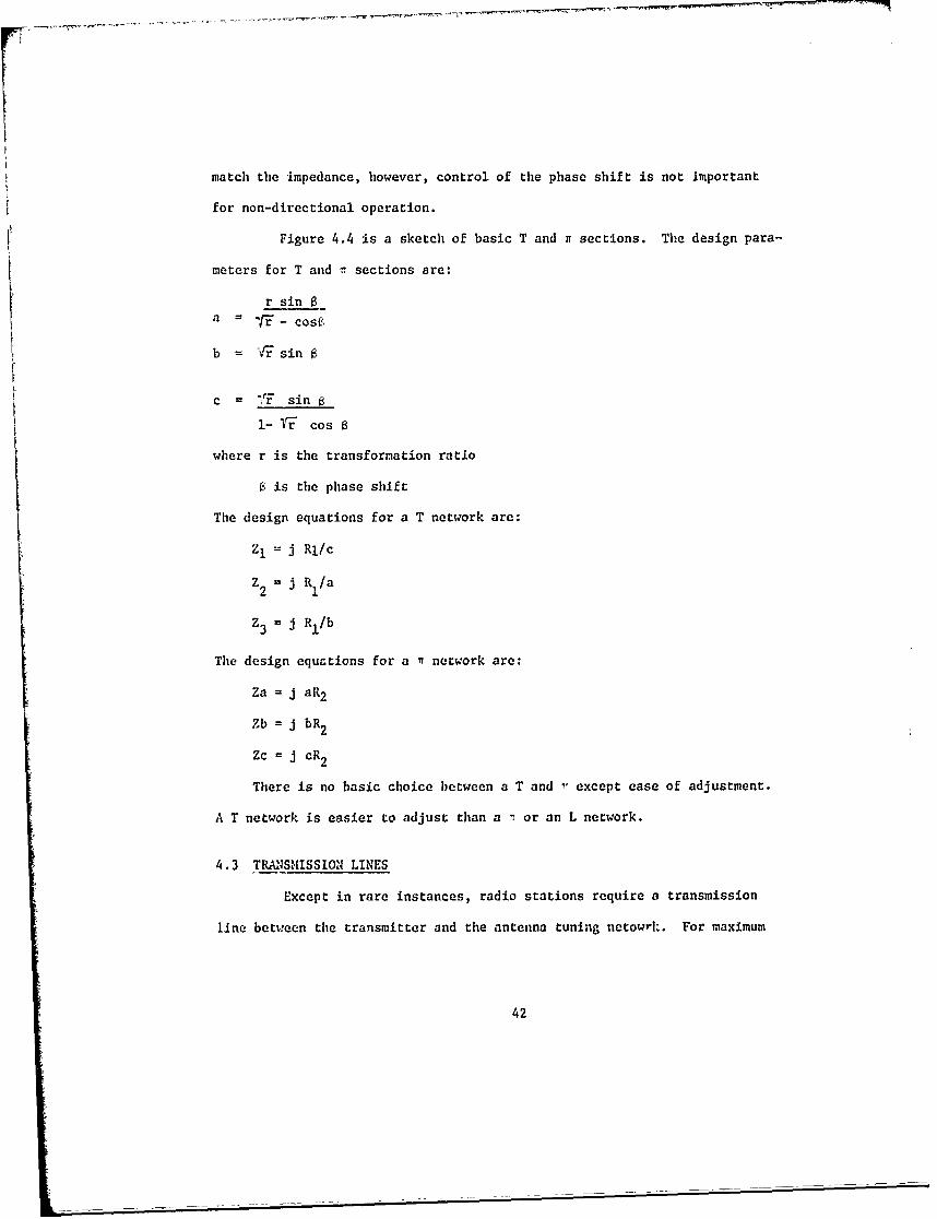
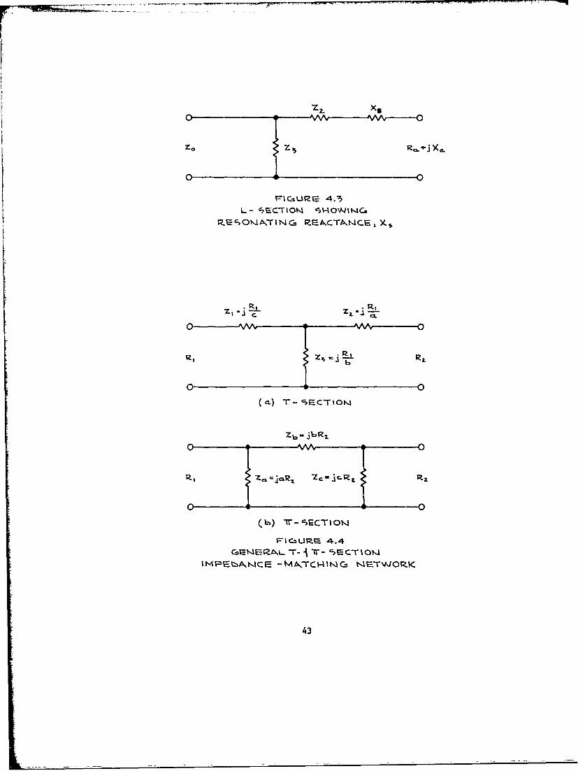
match the impedance, however, control of the phase shift is not important
for non-directional operation.
Figure 4.4 is a sketch of basic T and Tr sections. The design para-
meters for T and r sections are:
r sin B
a ='IF- cose
b = " sine
C = r sine
1- Y_ cos s
where r is the transformation ratio
6 is the phase shift
The design equations for a T network are:
Z= j Ri/c
Z2 = j RI/a
Z3 = j R1 /b
The design equations for a network are:
Za = j aR2
Zb = j bR2
Zc = j cR2
There is no basic choice between a T and r except ease of adjustment.
A T network is easier to adjust than a 7 or an L network.
4.3 TRANS'MISSION LINES
Except in rare instances, radio stations require a transmission
line between the transmitter and the antenna tuning netowrk. For maximum
42
0 -VF-CGUP-C 4.3
0 0
(a)T-CTO
Zb-j6R
frI Cz U P- 4.4
IMP~t>A.1CE -MA,-CV41NG NE.TWORK
43
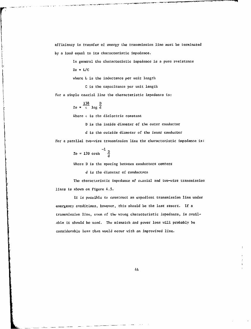
efficiency in transfer of energy the transmission line must be terminated
by a load equal to its characteristic impedance.
In general the characteristic impedance is a pure resistance
Zo = L/C
where L is the inductance per unit length
C is the capacitance per unit length
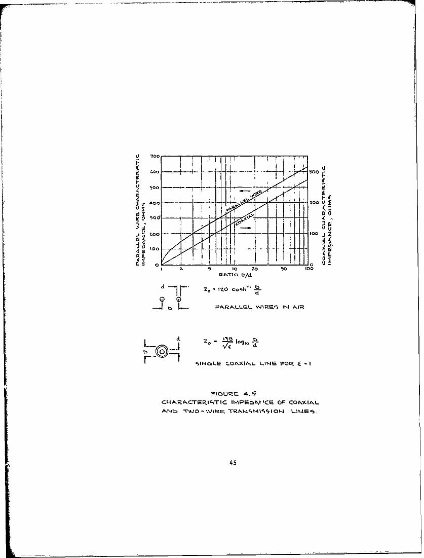
For a simple coaxial line the characteristic impedance is:
138 DZo= c log d
Where i is the dielectric constant
D is the inside diameter of the outer conductor
d is the outside diameter of the inner conductor
For a parallel two-wire transmission line the characteristic impedance is:
Zo = 120 cosh D
Where D is the spacing between conductors centers
d is the diameter of conductors
The characteristic impedance of cuaxial and two-wire transmission
lines is shown on Figure 4.5.
It is possible to construct an expedient transmission line under
emergency conditions, however, this should be the last resort. If a
transmission line, even of the wrong characteristic Impedance, is avail.-
able it should be used. The mismatch and power loss will probably be
considerable less than would occur with an improvised line.
44
2J 700
p) 40ooto
4DO-
El to
z. '5 10 2010 oRx~TIO bi d
Li ~ Z - 120 Cas~h' IL-
-.2 bPAJSZALLEL WISZE-7 I"- AIR
zo I a100
SINCALS C.OtYKI-AL LAWS4 FrOR 4E -I
FiCaut- 4. 5
CI-4ARA~CE~t;IM tPEbtA~t ICS Or- CONA~(ALA~N~ TJO - W r~ RAV4CMISe7I 014lII
45
V. EVALUATION OF FM ANTENNAS
5.0 GENERAL
The basic theory of antennas applies to FM as well as AM. However,
the smaller physical dimensions present entirely different design consid-
erations. One wavelength at FM frequencies is about ten feet. An FM
antenna does not utilize a ground system, and most are modifications of
a balanced dipole. freqcently FM antennas are stacked vertically to provide
power gain in the horizontal plane, and each element in the stack is refer-
red to as a bay. A four-bay antenna with an input power of 1 KW has an
effective radiated power of approximately 4 K. Primary F1 radiation is
horizontally polarized. A vertically polarized component is permissible
but not required under the FCC rules. The supporting tower is not an
integral part of the FM antenna but the metal structure near the antenna
can distort the radiation pattern and the input impedance. For this reason,
FM antennas must be designed to operate on specific types of towers to
achieve acceptable patterns and input impedances.
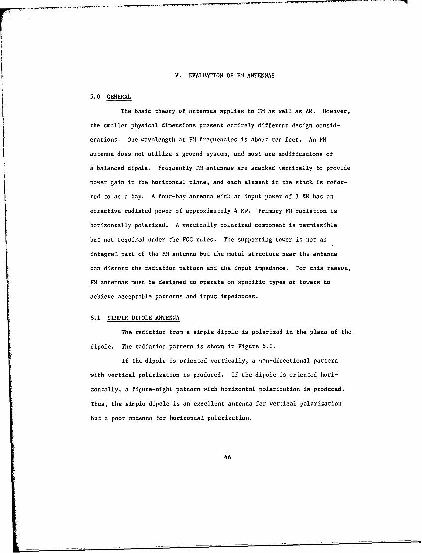
5.1 SIMPLE DIPOLE ANTENNA
The radiation from a simple dipole is polarized in the plane of the
dipole. The radiation pattern is shown in Figure 5.1.
If the dipole is oriented vertically, a non-directional pattern
with vertical polarization is produced. If the dipole is oriented hori-
zontally, a figure-eight pattern with horizontal polarization is produced.
Thus, the simple dipole is an excellent antenna for vertical polarization
but a poor antenna for horizontal polarization.
46
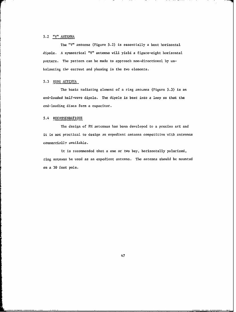
5.2 "V" ANTENNA
The "V" antenna (Figure 5.2) is essentially a bent horizontal
dipole. A symmetrical "V" antenna will yield a figure-eight horizontal
pattern. The pattern can be made to approach non-directional by un-
balancing the current and phasing in the two elements.
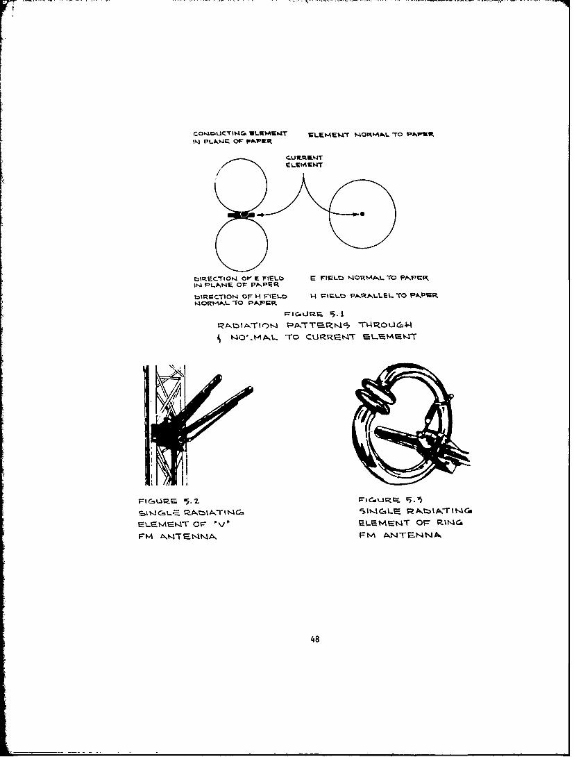
5.3 RING ANTENNA
The basic radiating element of a ring antenna (Figure 5.3) is an
end-loaded half-wave dipole. The dipole is bent into a loop so that the
end-loading discs form a capacitor.
5.4 RECO2IENDATIONS
The design of FM antennas has been developed to a precise art and
it is not practical to design an expedient antenna competitive with antennas
com .ercially available.
It is recommended that a one or two bay, horizontally polarized,
ring antenna be used as an expedient antenna. The antenna should be mounted
on a 30 foot pole.
47
co .AucTn4r- ULUWMUMT SLME4T NOMI TO PAWK~P~LA,4Q OF PAPIER
CU W.rEtVWT
Mj,I~O 4 Ole E FIELC E FI-LO t,4ORMA%.L TO PNVIRK11-4 PLANE OFr PA PER
t:1R CTION4 OF H F'IELD H Trr- PARP-LLEL TO PA~P.R
~4O .A.L-To CUVZ;t-4T f-Lr-VAEs4
-LaMSt4IT OF" ov F-%-Fvist4T Os= U~C
FMAWNt-4NA, FM A NTENNA,,
48
VI. SUMMARY AND RECOMMENDATIONS
6.0 SUMMARY
An expedient antenna may be deployed following the destruction of
the normal antenna to provide emergency information dissemination. It
is assumed that the normal antenna would be destroyed during severe
environmental disturbances and that the station personnel would have not
received a warning during the imminent phase. Under these assumed con-
ditions, non-technical personnel (announcer, etc.) should be ready to
disseminate emergency information in about 30 minutes. The technician
if not already on duty will probably arrive at the transmitter in approxi-
mately 30 minutes. Thus, the station personnel are ready to broadcast
emergency information at about the time the technician becomes available
to deploy an expedient antenna.
Assumed loss as the result of delay in transmission of emergency
information rises sharply at about one hour. For this reason a deployment
time goal has been set at 30 minutes after arrival of the technician at
the transmitter.
Should one or more towers of the regular antenna system remain
intact one of these towers should be used as a non-directional expedient
antenna. The time required to return to service using an existing tower
should not exceed 15 minutes.
If all towers are destroyed, an elevated horizontal wire
antenna should be deployed. (The detail design and performance character-
istics of an elevated -horizontal wire antenna are presented in Appendix A.
49
Procurement specifications for various frequencies and power levels are
presented in Appendix B.) If supporting poles have been installed in
advance it should be possible for one technician to deploy the packaged
horizontal wire antenna in less than 30 minutes.
As shown in the detail design, the horizontal wire antenna is very
inefficient, however, it should be a satisfactory expedient antenna for
most stations. In the relatively few cases where the horizontal wire is
inadequate, it may be desirable to deploy a top-loaded antenna. Due to the
time required to deploy a top-loaded antenna, however, the horizontal wire
antenna should be deployed to provide interim partial service. Estimated
time required for two technicians to deploy a top-loaded antenna ranges from
8 hours for 1600 kilz to over 24 hours for 540 kIIz.
The best expedient for FM is a one or two bay commercial antenna.
The antenna would be mounted on a thirty foot pole. Procurement speci-
fications for one and two bay antennas are contained in Appendix C.
A horizontal wire expedient antenna package to be supplied to
all AM stations in the Radio Broadcast Station Protection Program has been
designed. For selected stations a top-loaded antenna package may be
desirable.
As a minimum assistance to stations not in the Radio Broadcast
Station Protection Program, procedures for the construction of an expedient
antenna from available materials have been devised. Appendix D is a mono-
graph covering techniques for construction of these expedient antennas.
50
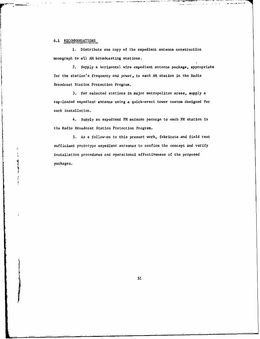
6.1 RECOMMENDATIONS
1. Distribute one copy of the expedient antenna construction
monograph to all AM broadcasting stations.
2. Supply a horizontal wire expedient antenna package, appropriate
for the station's frequency and power, to each AM station in the Radio
Broadcast Station Protection Program.
3. For selected stations in major metropolitan areas, supply a
top-loaded expedient antenna using a quick-erect tower custom designed for
each installation.
4. Supply an expedient FM antenna package to each FM station in
the Radio Broadcast Station Protection Program.
5. As a follow-on to this present work, fabricate and field test
sufficient prototype expedient antennas to confirm the concept and verify
installation procedures and operational effectiveness of the proposed
packages.
5
1 51
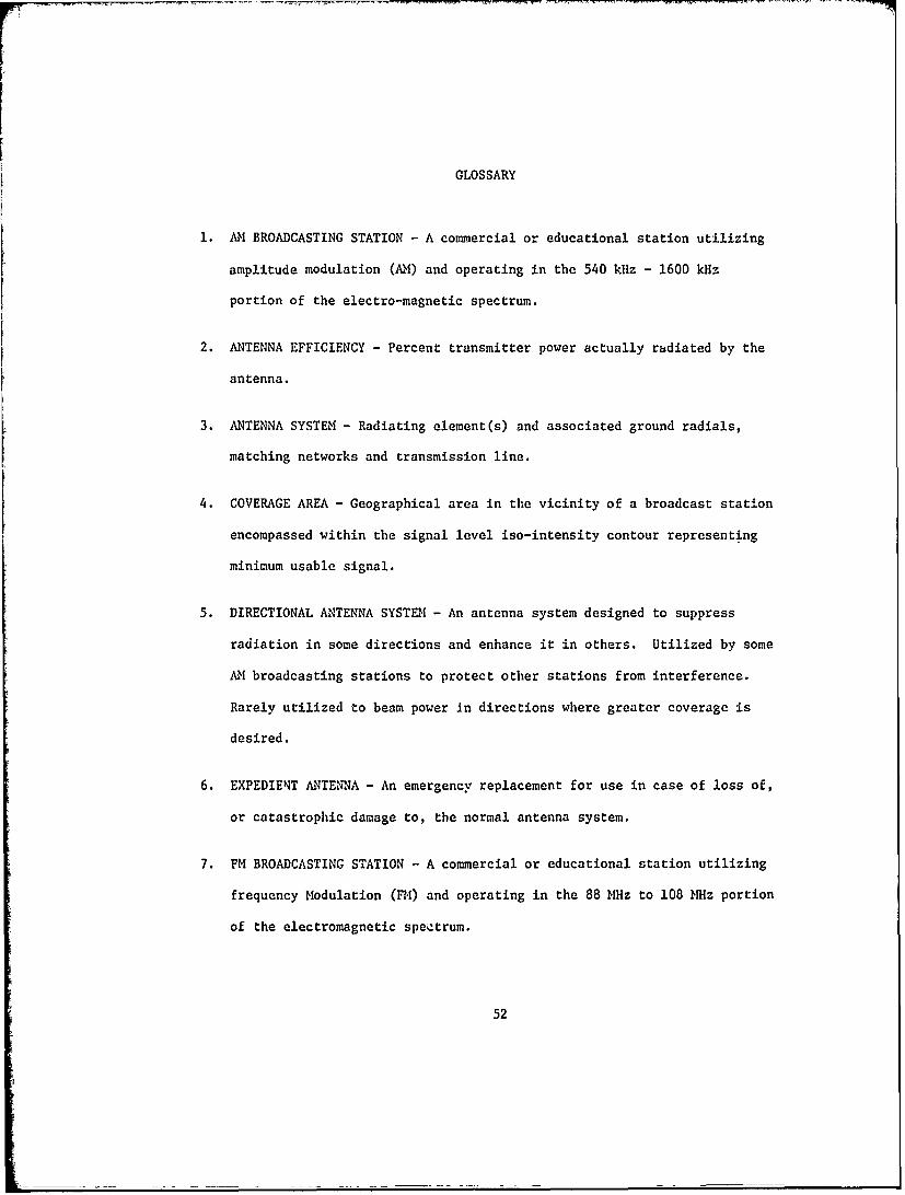
GLOSSARY
1. AM BROADCASTING STATION - A commercial or educational station utilizing
amplitude modulation (AM) and operating in the 540 kHz - 1600 kHz
portion of the electro-magnetic spectrum.
2. ANTENNA EFFICIENCY - Percent transmitter power actually radiated by the
antenna.
3. ANTENNA SYSTEM - Radiating element(s) and associated ground radials,
matching networks and transmission line.
4. COVERAGE AREA - Geographical area in the vicinity of a broadcast station
encompassed within the signal level iso-intensity contour representing
minimum usable signal.
5. DIRECTIONAL ANTENNA SYSTEM - An antenna system designed to suppress
radiation in some directions and enhance it in others. Utilized by some
AM broadcasting stations to protect other stations from interference.
Rarely utilized to beam power in directions where greater coverage is
desired.
6. EXPEDIENT ANTENNA - An emergency replacement for use in case of loss of,
or catastrophic damage to, the normal antenna system.
7. FM BROADCASTING STATION - A commercial or educational station utilizing
frequency Modulation (F1) and operating in the 88 MHz to 108 MHz portion
of the electromagnetic spectrum.
52
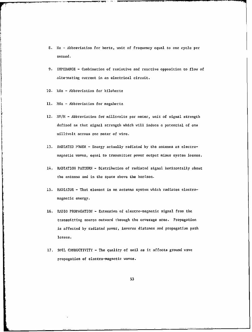
8. 11z - Abbreviation for hertz, unit of frequency equal to one cycle per
second.
9. IMPEDANCE - Combination of resistive and reactive opposition to flow of
alternating current in an electrical circuit.
10. kliz - Abbreviation for kilohertz
11. M z - Abbreviation for megahertz
12. MV/M - Abbreviation for millivolts per meter, unit of signal strength
defined as that signal strength which will induce a potential of one
millivolt across one meter of wire.
13. RADIATED POWER - Energy actually radiated by the antenna as electro-
magnetic waves, equal to transmitter power output minus system losses.
14. RADIATION PATTERN - Distribution of radiated signal horizontally about
the antenna and in the space above the horizon.
15. RADIATOR - That element in an antenna system which radiates electro-
magnetic energy.
16. RADIO PROPAGATION - Extension of electro-magnetic signal from the
transmitting source outward through the coverage area. Propagation
is affected by radiated power, inverse distance and propagation path
losses.
17. SOIL CONDUCTIVITY - The quality of soil as it affects ground wave
propagation of electro-magnetic waves.
53
18. TRANSMISSION LINE - Multi-element conductor usually co-axial cable
utilized by broadcasting stations to connect transmitter and antenna.
19. TRANSMITTER - Device utilized to generate and modulate electro-
magnetic energy of appropriate frequency and power for broadcast use.
20. TRANSMITTER EFFICIENCY - Ratio of input electric power to transmitter
output power expressed in percent.
21. TRANSMITTER POWER - Transmitter power output usually expressed in watts.
22. UNATTENUATED INVERSE FIELD - A reference field intensity expressed in
MV/M at one mile, related to radiated power and the radiation paLtern.
23. WAVELENGTH - The length of one complete electro-magnetic wave or cycle.
Wavelength is frequency dependent.
54
BIBLIOCRAPHY
"Antenna Systems," AF Manual 52-10, June 1953.
Jordan, E. C., Ed. Electromagnetic Theory and Antennas, MacMillanCompany, 1963.
Jasik, H., Ed. Antenna Engineering Handbook, McGraw Hill, 1961.
Kraus, J. D., Antennas, McGraw-Hill, 1950.
Laport, E. A., Radio Antenna Engineering, McGraw-Hill, 1952.
Leonhard, J., Mattuck, R. D., and Pote, A. J., "Folded Unipole Antennas,"IRE Transactions - Antennas and Propagation, July 1955. pp. 111-116.
Schelkunoff, S. A. and Friis, H. T., Antennas, John Wiley & Sous, 1952.
Smith, C. E. and Johnson, E. M., "Performance of Short Antennas,"Proceedings of the IRE, October 1947. pp. 1026-38.
Walker, A. P., Ed. NAB Engineering Handbook, McGraw-Hill, 1950.
Zuhrt, H. Electromanetrche Strahlungsfelder, Springer-Verlag, 1953.
55

APPENDIX A
DETAILED DESIGN OF HORIZONTAL WIRE ANTENNA
A.0 GENERAL
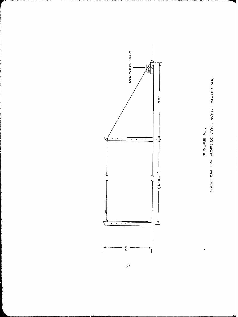
A horizontal wire antenna consists of an insulated wire above a
ground system. The feed point of the antenna is near the center of the
ground system. Figure A.1 is a sketch of the horizontal wire antenna
proposed for use as an expedient antenna system.
A.1 PHYSICAL DIMENSIONS
The total conducting ength was selected to be 0.2375 wavelengths
or 85.5 electrical degrees. Nominal antenna input impedance for this
length is 35 + jO ohms. The physical length of the conductor is a function
of frequency:
Length = 234,000/f
where f is the frequency in kHz
The principal part of the antenna is supported by insulators on
two 30 foot wood poles. The distance between the poles is a function of
frequency and is 80 feet less than the wire length. The conductor is #10
copper clad braided wire.
A.2 INPUT IMPEDANCE
Theoretical antenna input impedance is 35 + JO ohms. Actual
impedance may vary substantially. For design purposes it is assumed that
the actual input impedance may be any value within the range of 20 ± jlO0 ohms
to 48 tj75 ohms.
56
--- --- -
0.01 4
Lo
t5
U 0
57
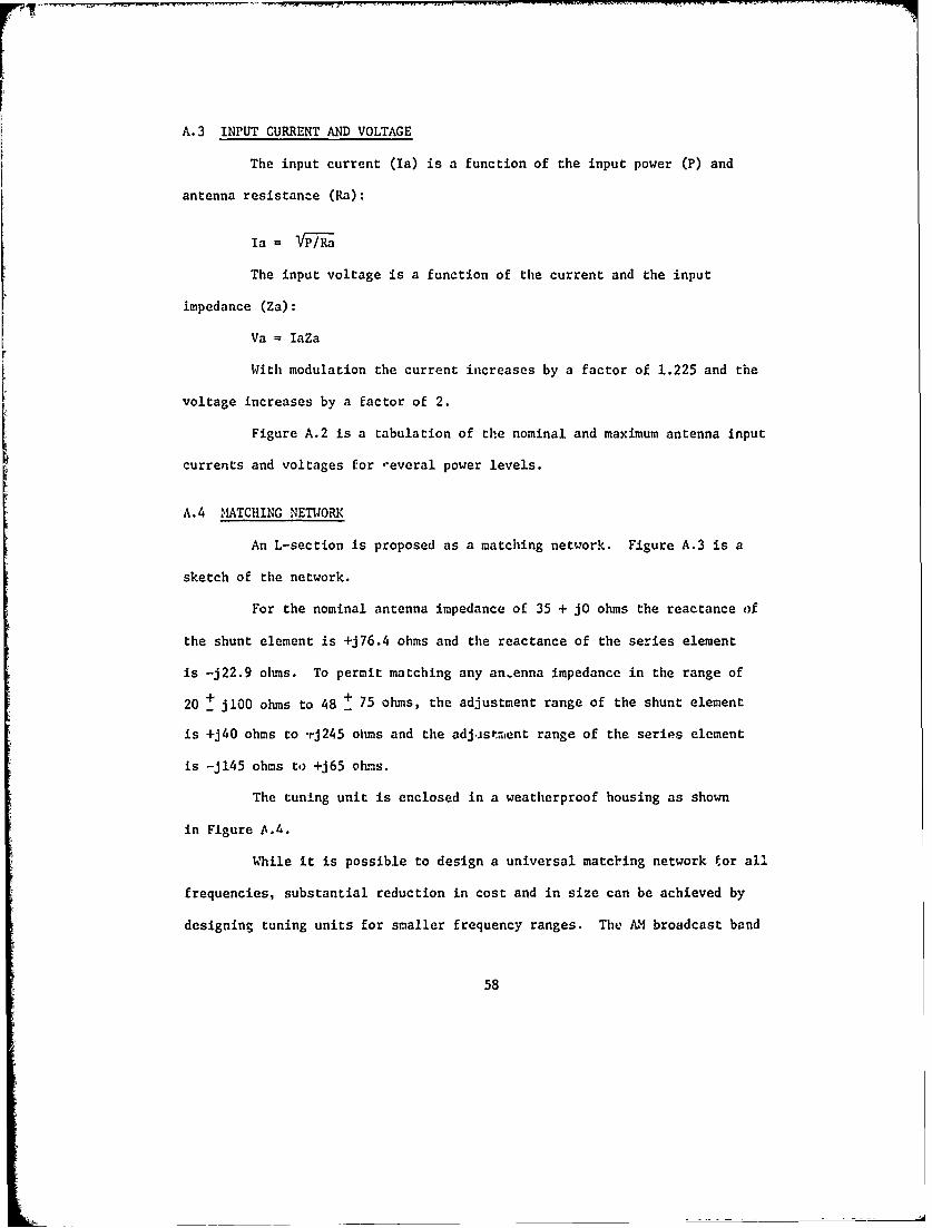
A.3 INPUT CURRENT AND VOLTAGE
The input current (Ia) is a function of the input power (P) and
antenna resistance (Ra):
Ia =Vi/i
The input voltage is a function of the current and the input
impedance (Za):
Va = laZa
With modulation the current increases by a factor of 1.225 and the
voltage increases by a factor of 2.
Figure A.2 is a tabulation of the nominal and maximum antenna input
currents and voltages for *everal power levels.
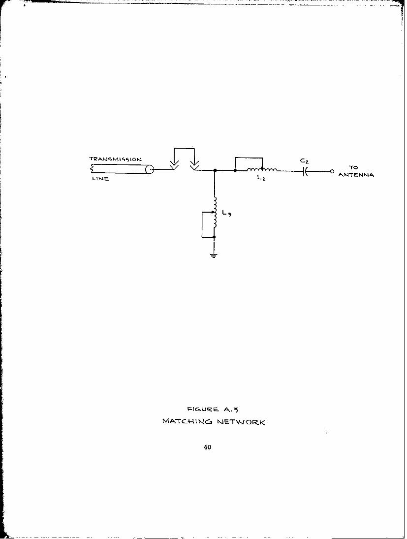
A.4 MATCHING NETWORK
An L-section is proposed as a matching network. Figure A.3 is a
sketch of the network.
For the nominal antenna impedance of 35 + jO ohms the reactance of
the shunt element is +j76.4 ohms and the reactance of the series element
is -j22.9 ohms. To permit matching any an.enna impedance in the range of
20 + jl00 ohms to 48 + 75 ohms, the adjustment range of the shunt element
is +j40 ohms to -rj245 ohms and the adj.stment range of the series element
is -j145 ohms to +j65 ohms.
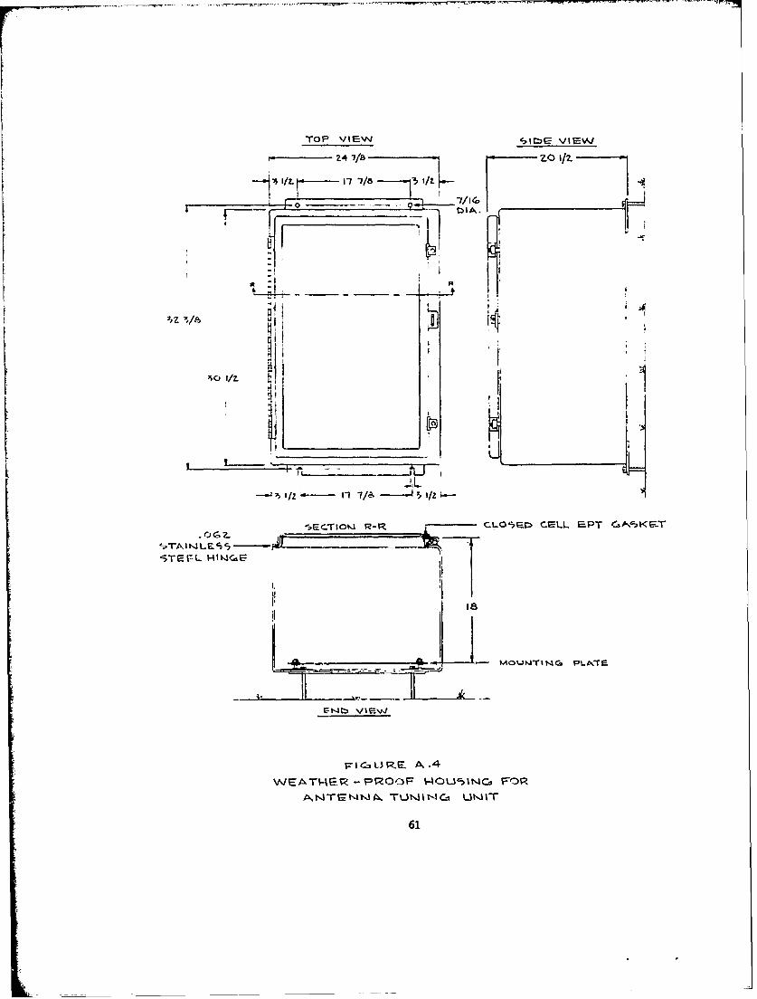
The tuning unit is enclosed in a weatherproof housing as shown
in Figure A.4.
While it is possible to design a universal matching network tor all
frequencies, substantial reduction in cost and in size can be achieved by
designing tuning units for smaller frequency ranges. The AM broadcast band
58

Without Moulation
Power Input Current RMS Input VoltaSe
Nominal flax. Nominal Max.
.25 KW 2.7 amps 3.5 amps 95 volts 357 volts
1.0 KW 5.4 amps 7.1 amps 189 volts 724 volts
5.0 K1 12.0 amps 15.8 amps 420 volts 1611 volts
10.0 K1 16.9 amps 22.4 amps 592 volts 2284 volts
With Modulation
Power Input Current Peak Input Voltage
Nominal Max. Nominal Max.
.25 KW 3.3 amps 4.3 amps 269 volts 1010 volts
1.0 KW 6.6 amps 8.7 amps 535 volts 2048 volts
5.0 KW 14.7 amps 19.4 amps 1188 volts 4557 volts
10.0 KW 20.7 amps 27.4 amps 1674 volts 6460 volts
Figure A.2
Antenna Input Current and Voltage
59
"r ' t ' 1 c '%I°I I ( -,T OLINE LZ
60
TOP VIEW SI.C VIEWJ
Z4 7/8 ZO 1/2.
7,__ -1/VI7/I51/
17 1 - )P--A.WETE RO O5N- O
T.31 G Um-
sETIKIR- CO'1 C~L ~T61K-
has been divided into four regions for convenience; 540 to 750 kHz,
750 to 1000 kIz, 1000 to 1300 kHz, and 1300 to 1600 kHz. Matching net-
works have been designed for usc within each of these regions.
Since the size of the components in the matching network is
dependent on the power, high and low power units have been designed. A
total of ten different matching networks have been designed; for each of
four frequency regions plus a universal and in each case for power levels
of 1 KW and 10 KW. The parts required for each of these units are
tabulated in Appendix B.
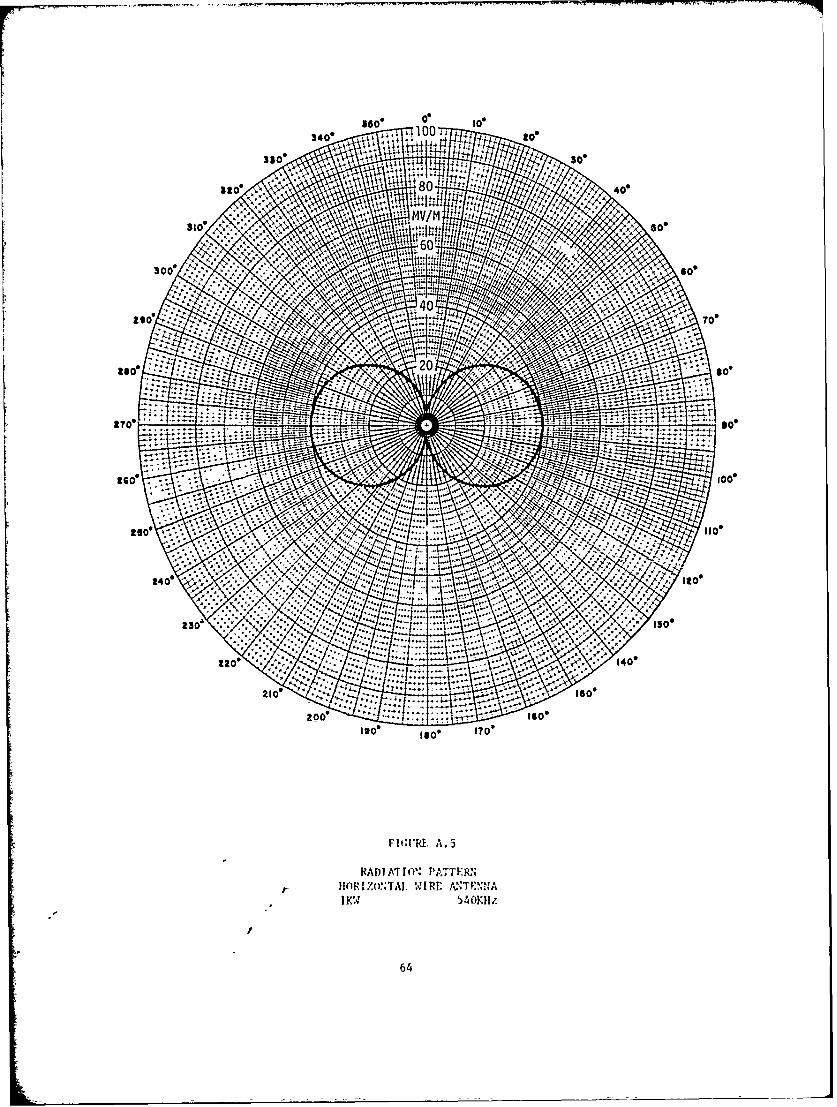
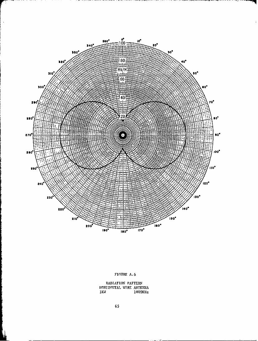
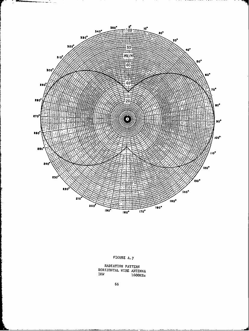
A.5 RADIATION PATTERN
The radiation in the horizontal plane from an elevated horizontal
wire is not reidily amenable to exact mathematical anclysis. By making
several simplifying approximations, however, it is possible to arrive at a
predicted approximate radiation pattern. Actual radiation may diverge sub-
stantially from the predicted.
The radiation pattern of a dipole in free-space is well known.
Maximum radiation is perpendicular to the antenna and there are nulls off
the ends. A horizontal antenna located on a perfectly conducting surface
radiates no energy in the horizontal plane. The entire energy is radiated
above the plane.
Neither of the above cases corresponds closely to the actual
antenna, but both are conceptually useful for analysis.
62
One simplification is to assume that the antenna is a slant wire
with a constant slope equal to the average slope of the elevated wire
antenna. The horizontal radiation pattern for a slant wire antenna in free-
space is given by:
E' = vsin 2 + (cos 0 sin a) 2
where 0 is the slope angle
a is the azimuth angle.
The magnitude of the radiation is a function of the average slope of
the antenna and close-in ground conductivity. For a slope of 00 the radiation
in the horizontal plane is zero and for a slope of 900 the radiation is about
190 mv/m at one mile for 1 KW input power. The radiation is assumed to
increase as the sine of the antenna slope. If the ground is not perfectly
conducting, there is an energy loss in the image antenna which results in
an unbalanced dipole radiation. The unbalance results in some radiation in
the horizontal plane. None of the methods of predicting the radiation appear
to correspond closely to the experimental. While experimental results
have differed radically, it appears that the radiation from the elevated
horizontal wire at 540 kHrz will be about 40 mv/m at one mile for 1 KW.
Since average slope and ground conductivity effects increase with frequency,
the antenna should be more efficient at higher frequencies. The radiation is
assumed to be 70 mv/m at 1000 kflz and 100 mv/m at 1600 kflz. The assumed
radiation patterns for 540, 1000, and 1600 k|iz are shown on Figures A.5,
A.6, and A.7 respectively. Figure A.8 is a tabulation of the predicted
service areas assuming ground conductivities of 2 mmho/m and 8 mmho/m.
63
i V
Igo loWW
2600 "..T --
48 40*Ito*
II0e 179
FJ(rR A.00
RADJATJO, ;KTIR
24e I64
2800
1,0 lase7
FIgUR so'
1KW 1001K-
24d l65
35003400 014". go*
3300300
8 40*
310, -mv/m1.11,
itfil 1' 4 0
60300*
Goo
29 o
k Too
Ise
so*
ItToo
i0o,
250 -1101,
240'Ito*
2300130*
2201404
210 o 4+Ifloo
zoo* 14 soIgo* Isoo ITO*
FIGURE A-7
RADIATION PATTERNHORrZONTAL WIRE ANTENNAlKW 1600KI17
66

Distance to Contour
1 KW - 540 KflzDistance to Contour (0.5 mv/m)
0 E(mv/m) 2 MMHOS/M 8 MMHOS/M[ 5.2 6.2 9.510 8.6 8.8 14.520 14.5 12.3 20.530 20.5 15.0 26.540 26.0 17.0 31.050 30.8 19.0 35.060 34.7 20.0 38.070 37.6 20.6 40.080 39.4 21.0 40.590 40 21.2 41.0
1 KW - 1000 KHzDistance to Contour (0.5 mv/m)
E(mvim) 2 NNIIOS/M 8 IMHOS/M
0 15.1 7.0 14.010 19.2 7.8 16.020 27.9 9.4 19.530 37.4 10.7 22.540 46.5 12.0 25.550 54.8 12.8 27.560 61.1 13.6 29.070 66.0 J4.0 30.080 69.0 14.4 30.590 70.0 14.5 30.7
1 K1 - 1600 KllzDistance to Contour (0.5 mv/m)
0 E(mv/m) 2 MNOS/M 8 MNIOS/M
0 30.9 6.3 13.210 35 6.7 14.020 44.9 7.6 15.730 56.7 8.4 17.540 68.5 9.2 18.850 79.1 9.8 20.060 88 10.3 21.070 94.6 10.7 21.580 98.6 10.8 21.990 100 11.0 22.2
Figure A.8
67
APPENDIX B
AM EXPEDIENT ANTENNA
PROCUREMENT SPECIFICATIONS AND INSTALLMENT INSTRUCTIONS
B.O GENERAL
Procurement specifications have been prepared for expedient horizon-
tal wire antennas. Separate parts lists are included for several power and
frequency combinations.
Instructions for the deployment of the antennas described in
procurement specifications are included.
B.1 PROCURDIENT SPECIFICATIONS
The procurement package consists of two treated wood poles installed
at the transmitter site, #10 stranded copper clad steel wiremounting hard-
ware, insulators, and an antenna tuning unit.
Since the size of some components is dependent on power and frequency,
several different parts lists are included. The parts that are independent
of power and frequency are tabulated as Miscellaneous Parts on Figure B.11.
Figures B.1, B.2, B.3, and B.4 list the frequency dependent parts for a
power of I KW for the frequency ranges 540 to 750 klz, 750 to 1000 kHz,
1000 to 1300 kHz, and 1300 to 1600 kHz respectively. Figure B.5 is a list
of the parts for a 1 KW universal frequency range (540 to 1600 kHz) antenna
package. Figures B.6, B.7, B.8 and B.9 are lists of the frequency dependent
parts for a power of 10 KW for the frequency ranges of 540 to 750 kHz,
750 to 1000 kHz, 1000 to 1300 kllz, and 1300 to 1600 kHz respectively.
Figure B.10 is a list of the parts for a 10 KW universal frequency range
package.
68
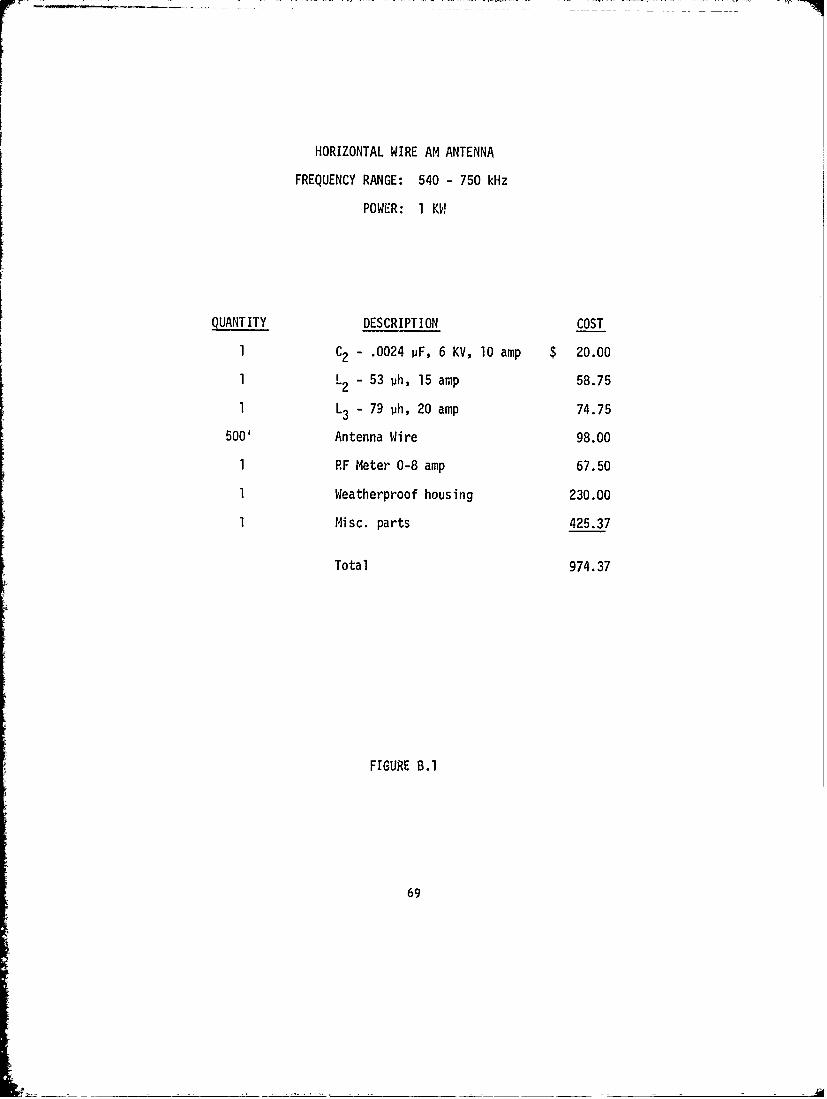
HORIZONTAL WIRE AM ANTENNA
FREQUENCY RANGE: 540 - 750 kHz
POWER: 1 KW
QUANTITY DESCRIPTION COST
1 C2 - .0024 pF, 6 KV, 10 amp $ 20.00
1 L - 53 ph, 15 amp 58.75
1 L3 - 79 ph, 20 amp 74.75
500' Antenna Wire 98.00
1 RF Meter 0-8 amp 67.50
1 Weatherproof housing 230.00
1 Misc. parts 425.37
Total 974.37
FIGURE B.1
69
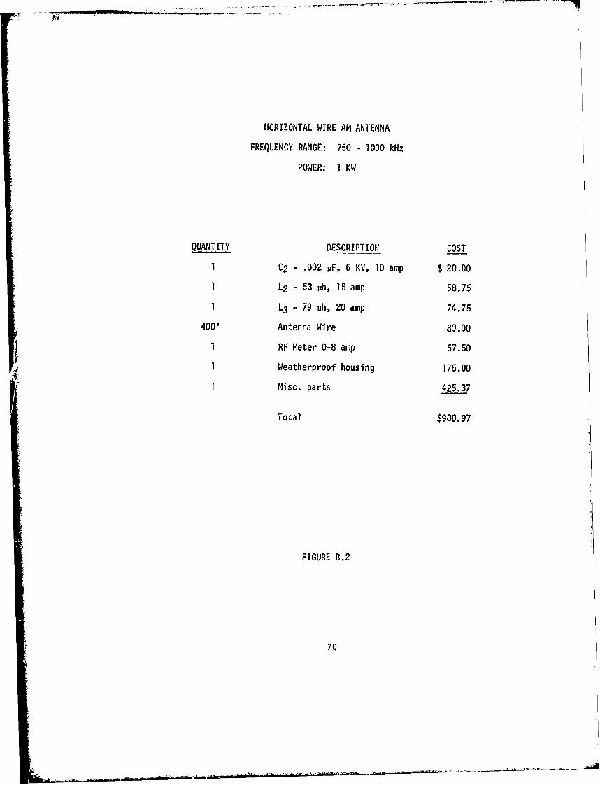
HORIZONTAL WIRE AM ANTENNA
FREQUENCY RANGE: 750 - 1000 kHz
POWER: I KW
QUANTITY DESCRIPTION COST
1 C2 - .002 pF, 6 KV, 10 amp $ 20.00
1 L2 - 53 ph, 15 amp 58.75
1 L3 - 79 ph, 20 amp 74.75
400' Antenna Wire 80.00
1 RF Meter 0-8 amp 67.50
1 Weatherproof housing 175.00
1 Misc. parts 425.37
Total $900,97
FIGURE B.2
70
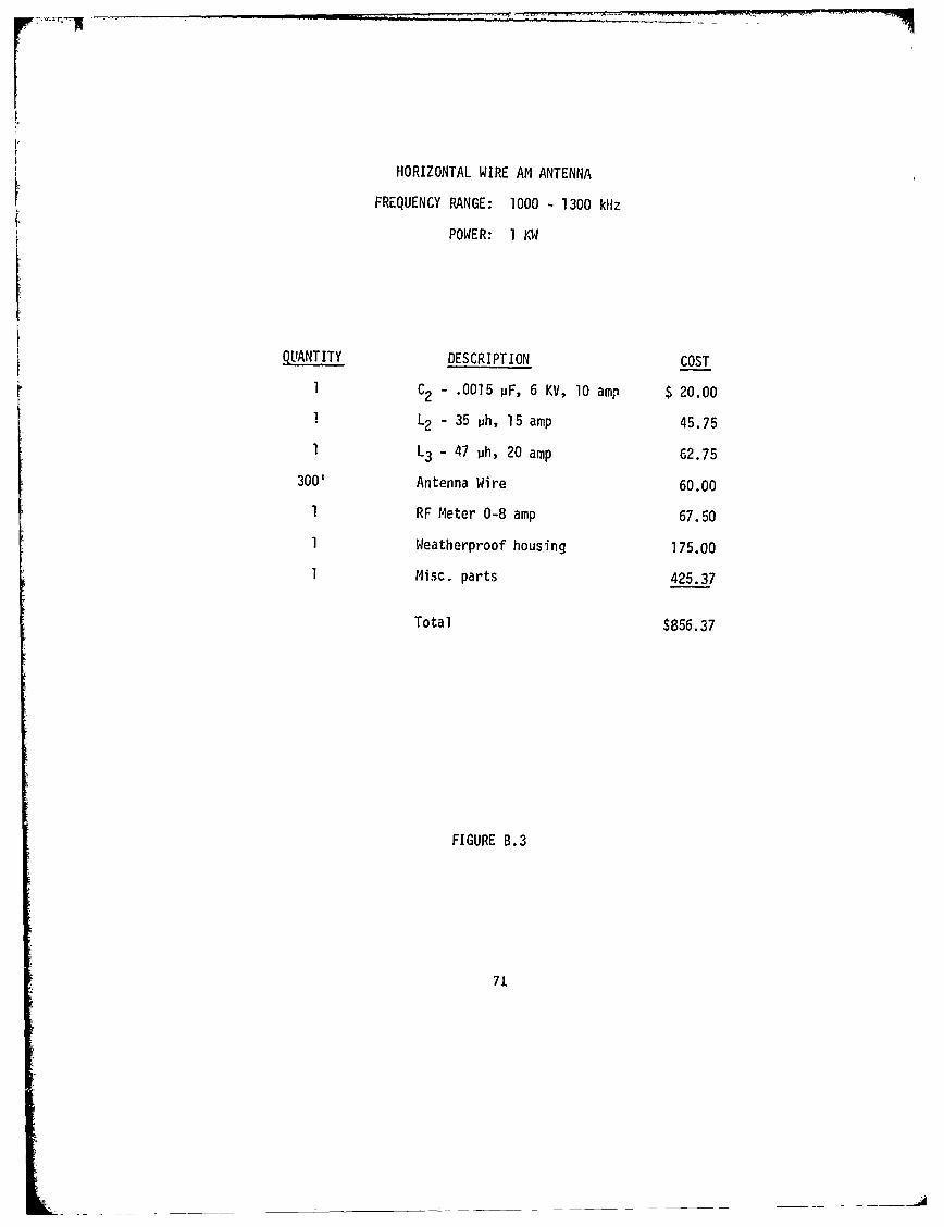
HORIZONTAL WIRE AM ANTENNA
FREQUENCY RANGE: 1000 - 1300 kHz
POWER: 1KW
QUANTITY DESCRIPTION COST
1 C2 - .0015 pF, 6 KV, 1O amp $ 20.00
1 L2 - 35 ph, 15 amp 45.75
1 L3 - 47 ph, 20 amp 62.75
300' Antenna Wire 60.00
1 RF Meter 0-8 amp 67.50
1 Weatherproof housing 175.00
1 Misc. parts 425.37
Total $856.37
FIGURE B.3
71

HORIZONTAL WIRE AM ANTENNA
FREQUENCY RANGE: 1300 - 1600 kfiz
POWER: 1 KW
QUANTITY DESCRIPTION COST1 C2 - .0012 pF, 6 KV, 10 amp $ 20.00
1 L2 - 32 ph, 15 amp 43.751 L3 - 32 ph, 20 amp 60.25
230' Antenna Wire 45.00
1 RF Meter 0-8 amp 67.50
1 Weatherproof housing 175.00
1 Misc. parts 425.37
Total $836.87
FIGURE B.4
72
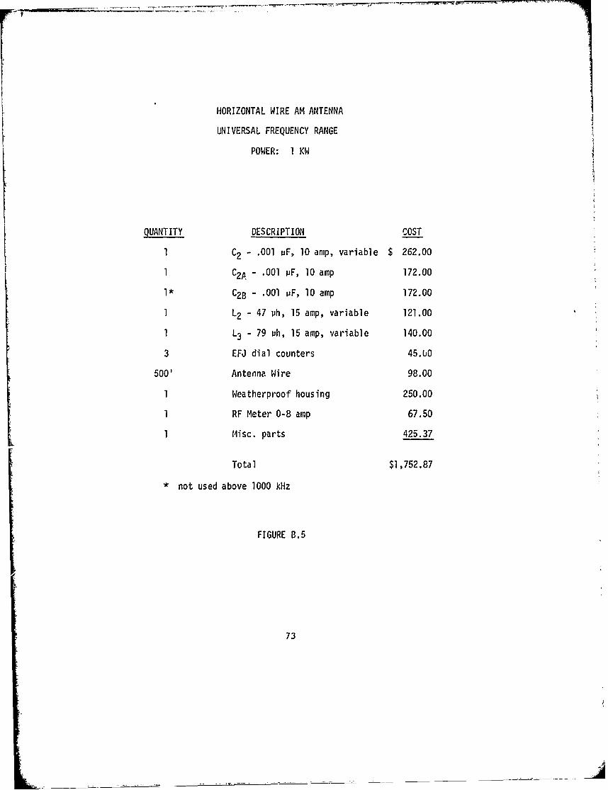
HORIZONTAL WIRE AM ANTENNA
UNIVERSAL FREQUENCY RANGE
POWER: I KW
QUANTITY DESCRIPTION COST
1 C2 - .001 iF, 10 amp, variable $ 262.00
1 C2A- .001 PF, 10 amp 172.00
1* C2B - .001 uF, 10 amp 172.00
1 L2 - 47 ph, 15 amp, variable 121.00
1 L3 - 79 ph, 15 amp, variable 140.00
3 EFJ dial counters 45.bO
500' Antenna Wire 98.00
1 Weatherproof housing 250.00
1 RF Meter 0-8 amp 67.50
1 Misc. parts 425.37
Total $1,752.87
* not used above 1000 kHz
FIGURE B.5
73
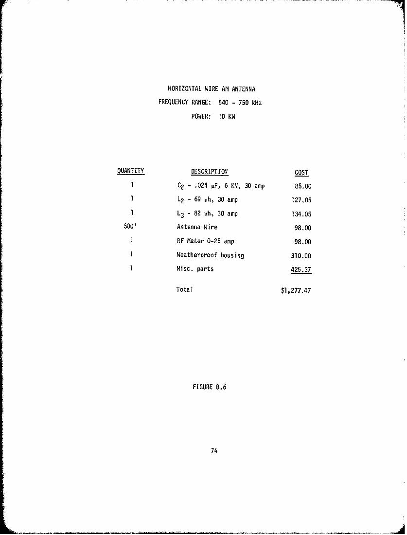
HORIZONTAL WIRE AM ANTENNA
FREQUENCY RANGE: 540 - 750 kHz
POWER: 10 KW
QUANTITY DESCRIPTION COST
1 C2 - .024 pF, 6 KV, 30 amp 85.00
1 L2 - 69 ph, 30 amp 127.05
1 L3 - 82 ph, 30 amp 134.05
500' Antenna Wire 98.00
1 RF Meter 0-25 amp 98.00
1 Weatherproof housing 310.00
1 Misc. parts 425.37
Total $1,277.47
FIGURE B.6
74
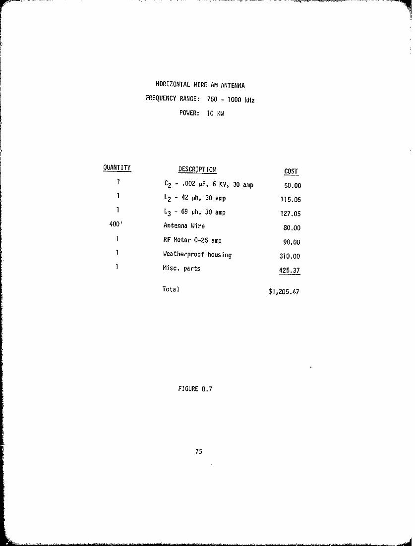
HORIZONTAL WIRE AM ANTENNA
FREQUENCY RANGE: 750 - 1000 kHz
POWER: 10 KW
QUANTITY DESCRIPTION COST
I C2 - .002 uF, 6 KV, 30 amp 50.00
1 L2 - 42 uh, 30 amp i15.05
1 L3 - 69 ph, 30 amp 127.05
400' Antenna Wire 80.00
1 RF Meter 0-25 amp 98.00
1 Weatherproof housing 310.00
1 Misc. parts 425.37
Total $1,205.47
FIGURE B.7
75
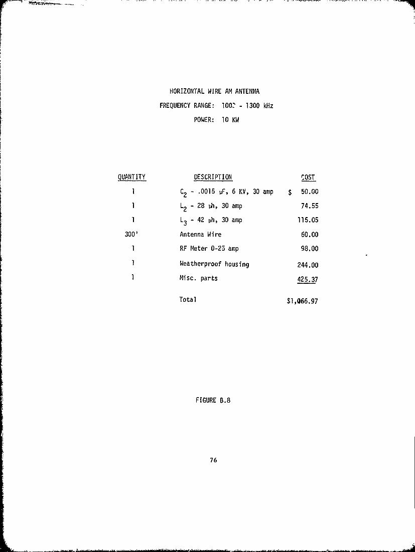
HORIZONTAL WIRE AM ANTENNA
FREQUENCY RANGE: 1002 - 1300 kHz
POWER: 10 KW
QUANTITY DESCRIPTION COST
1 C2 - .0015 uF, 6 KV, 30 amp $ 50.00
1 L2 28 th, 30 amp 74.55
1 L3 - 42 ph, 30 amp 115.05
300' Antenna Wire 60.00
1 RF Meter 0-25 amp 98.00
1 Weatherproof housing 244.00
1 Misc. parts 425.37
Total $1,066.97
FIGURE B.8
76

HORIZONTAL WIRE AM ANTENNA
FREQUENCY RANGE: 1300 - 1600 kHz
POWER: 10 KW
MUANITY DESCRIPTION COSTI C2 - .0012 pF, 6 KV, 30 amp $ 50.00
1 L2 --22 ph, 30 amp 72.55
1 L3 - 42 ph, 30 amp 115.05
230' Antenna Wire 45.00
1 RF Meter 0-25 amp 98.00
Weatherproof housing 244.00
1 Misc. parts 425.37
Total $1,049.97
FIGURE B.9
77
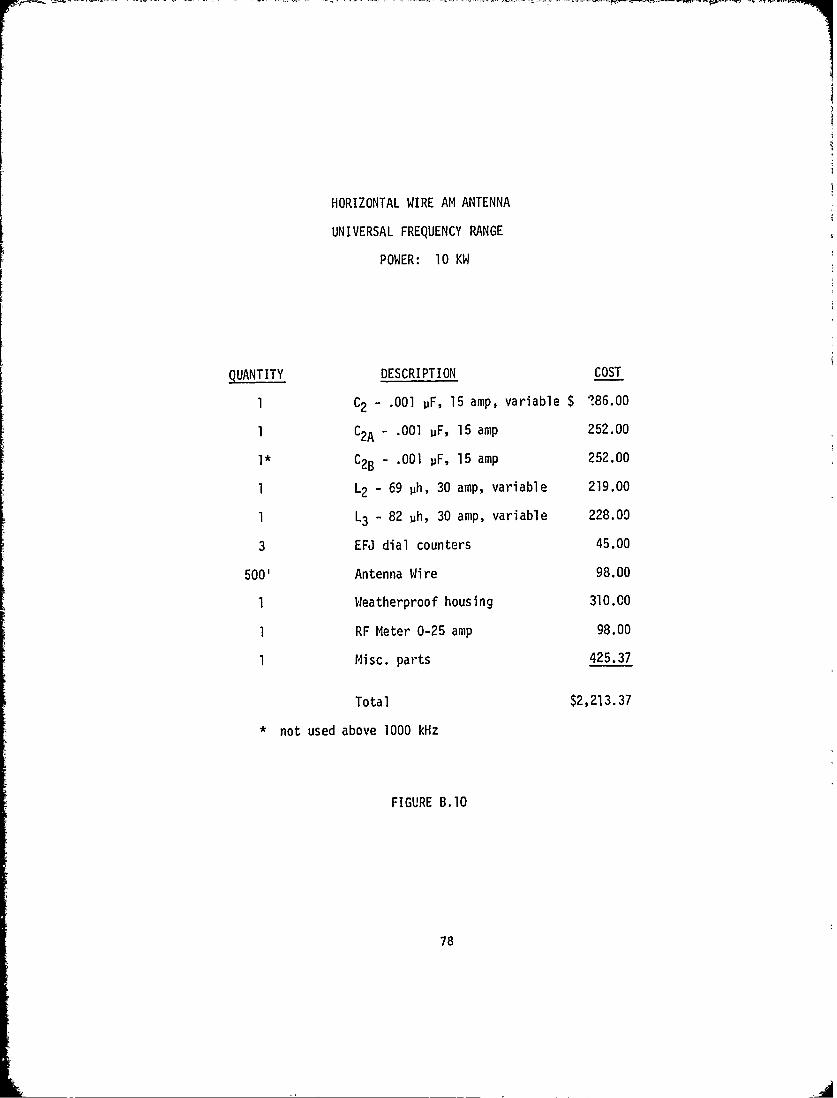
HORIZONTAL WIRE AM ANTENNA
UNIVERSAL FREQUENCY RANGE
POWER: 10 KW
QUANTITY DESCRIPTION COST
1 C2 - .001 pF, 15 amp, variable $ 186.00
1 C2A - .001 uF, 15 amp 252.00
1* C2B - .001 pF, 15 amp 252.00
1 L2 - 69 ph, 30 amp, variable 219.00
1 L3 - 82 ph, 30 amp, variable 228.00
3 EFJ dial counters 45.00
500' Antenna Wire 98.00
1 Weatherproof housing 310.00
1 RF Meter 0-25 amp 98.00
1 Misc. parts 425.37
Total $2,213.37
* not used above 1000 kHz
FIGURE B.10
78
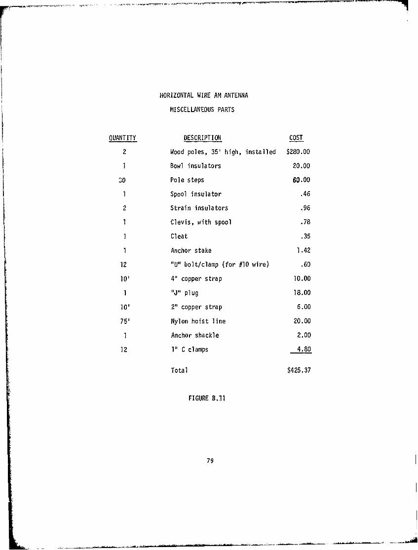
HORIZONTAL WIRE AM ANTENNA
MISCELLANEOUS PARTS
QUANTITY DESCRIPTION COST
2 Wood poles, 35' high, installed $280.00
1 Bowl insulators 20.00
30 Pole steps 60.00
I Spool insulator .46
2 Strain insulators .96
1 Clevis, with spool .78
1 Cleat .35
1 Anchor stake 1.42
12 "U" bolt/clamp (for #10 wire) .60
10' 4" copper strap 10.00
1"J" plug 18.00
10' 2" copper strap 6.00
75' Nylon hoist line 20.00
I Anchor shackle 2.00
12 1" C clamps 4.80
Total $425.37
FIGURE B.1I
79

The component prices are based on current manufacturer's catalogs.
The cost of procuring and erecting the wood poles will vary with locality.
The labor cost of assembling the components into an expedient antenna
package is not included.
s
so
4
B.2 INSTALLATION INSTRUCTIONS: AM EMERGENCY ANTENNA
B.2.1. GENERAL
This emergency antenna kit contains, with the exception of support
poles, the complete assortment of hardware and materials necessary for
the deployment of a useable emergency antenna system. The emergency
antenna will consist of a nearly horizontal, quarter wave radiator
supported approximately thirty feet above ground and the minimum coupling
circuitry required to match antenna impedance to the transmitter. Since
the existing ground radials will be an essential component of the emergency
antenna system, it is important that the colupling point be centrally loc-
ated with respect to the ground radials despite the difficulties which may
be encountered with the remains of the fallen tower.
Deployment will be accomplished in two phases, Preliminary Prepa-
tion and Emergency Deploynent. Preliminary preparations are to be carried
out as soon as the kit is received and will consist mainly of procuring
and installing two support poles. Pole steps and wire holders are re-
quired to be installed prior to setting the poles as a convenience and
to save time should emergency deployment become necessary.
Emergency deployment will be made only after the original antenna
system has been damaged beyond use and will consist principally of instal-
ling a wire radiating element on the support poles and coupling the antenna
to the transmitter.
The following installaton instructions are of necessity broad in
application because of the great variety of conditions whiLh may exist at
81
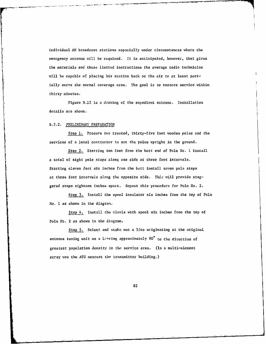
individual AM broadcast stations especially under circumstances where the
emergency antenna will be required. It is anticipated, however, that given
the materials and these limited instructions the average radio technician
will be capable of placing his station back on the air to at least part-
ially serve the normal coverage area. The goal i3 to restore service within
thirty minutes.
Figure B.12 is a drawing of the expedient antenna. Installation
details are shown.
B.2.2. PRELIMINARY PREPARATION
Step 1. Procure two treated, thirty-five foot wooden poles and the
services of a local contractor to set the poles upright in the ground.
Step 2. Starting ten feet from the butt end of Pole No. 1 install
a total of eight pole steps along one side at three foot intervals.
Starting eleven feet six inches from the butt install seven pole steps
at three foot intervals along the opposite side. This will provide stag-
gered steps eighteen inches apart. Repeat this procedure for Pole No. 2.
Step 3. Install the spool insulator six inches from the top of Pole
No. 1 as shown in the diagram.
Step 4. Install the clevis with spool six inches from the top of
Pole No. 2 as shown in the diagram.
Step 5. Select and stake out a line originating at the original
antenna tuning unit on a *evring approximately 900 to the direction of
greatest population density in the service area. (In a multi-element
array use the ATU nearest the transmitter building.)
82
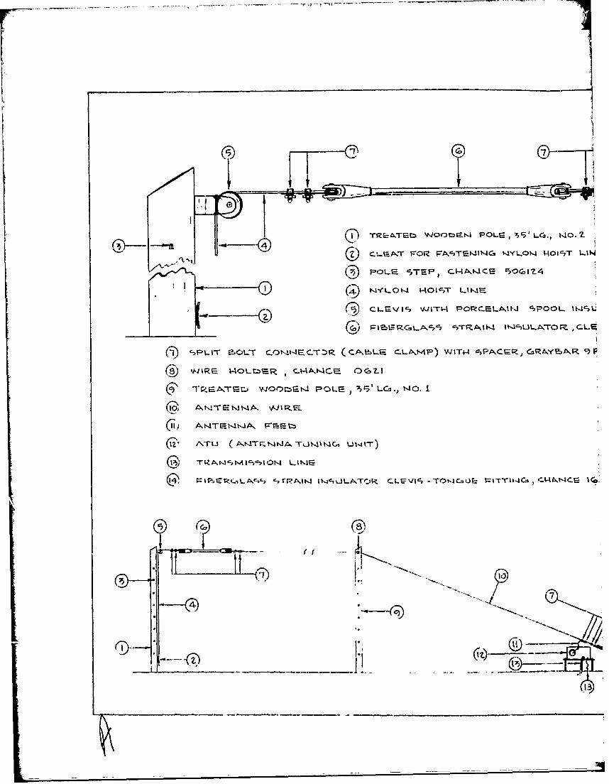
03-r
I ~ ~ PL ~TEb V'JOOM PE, C5' LC t40.
--0 ~ )CLEICc, VJITI-4 POFZ(.EL4JkI "7ROOL IM'iCL
(~)Fl C5L~~ ~T~lM tIc-ULATOr.P- cLrm
(t)c7PLJT .OL-r CO1t!,-1L.TG C..LA\MP) WJIT4-4 ciPACGR, GRANYeU4R c r
WTEk=-t44A vFr.F-r
S F t$',c~tR;AIW~ I~cvLA.Te-R CLE;'Jl ;=I~V FITW-JCM, -CE C 1<2
*17
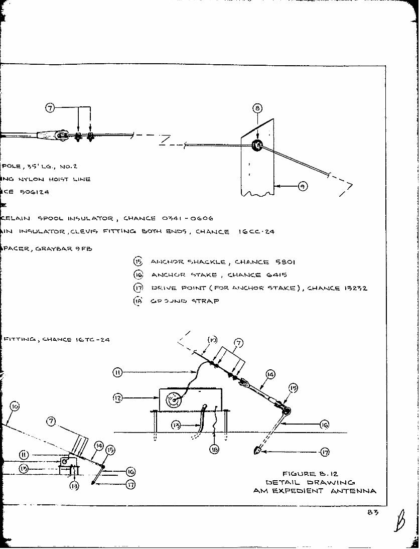
G OL,5LG., NO.Z7
l4C VLOI-.4 4Ic7T II-l
CE 9:OGo1 /
E=LAJNJ, 'SPOOL IWULA,LTOR. C-A4AN'~C-S Or41 -OGO(a
I4t--,LLAXTOR ,CLE' ~ FrT1 ,4Cm fOTAA -~ t.t6, C)A,4tC. IGCC..Z.4
PAC.GR, GRYA F2,___
V:P.V POIt'4T (FOR t4Ctior csT4KE), cw-4c.F P:5z 7 y?
CAP -. t~t ITA
>-t3t'CCR V
t=T6A- CHJVSIGC-4
1cM 1)~~T ~ N
fI
Step 6. Set Pole No. I on the line seventy-five feet from the ATU.
Step 7. Set Pole No. 2 at a distance from Pole No. 1 such that the
total antenna wire length (the slant segment plus the horizontal) ,;Ill equal
0.2375 wave lengths at the operating frequency. This distance may be
determined from Figure B.13 which is a graph of required pole separation vs.
frequency.
Step 8.,Install the Cleat on Pole No. 2 directly under the insulated
pulley and approximately five feet above ground. This completes prelimin-
ary preparations.
B.2.3 EMERGENCY DEPLOYMENT
Step 1. Remove contents of kit and check parts against parts list,
Figure B.14. Deficiencies, if any, should be made up from components
available at the station.
Step 2. Select a location for the emergency antenna tuning unit
where the terminal end of the transmission line may be connected to the
terminal provided in the emergency antenna tuning unit. (The installer
should make every effort to achieve a direct connection, but should this be
impossible an extension of the center conductor must be improvised using a
short length of transmission line or other type of conductor.) The extension
should not exceed five feet in length.
Step 3. Set the emergency ATU in place and bond the copper ground
strap to the existing ground system making contact with as many radial
wires as possible. Contact points should be cleaned and soldered. Should
soldering equipment not be available r*ie "C" clamps provJded in the kit
should be used for firm ground connections. If a center-conductor extension
as described in Step 2 is necessary, a ground strap connecting the outer
84
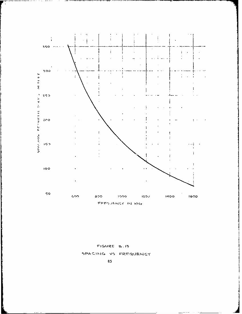
- I - L! . ..
* Ii
300
Zoo f 0I0 ot9 .'I, O
*" " I, - I, t t,, < --
C5
looI01000ZO 1400 1 GOO
I
85
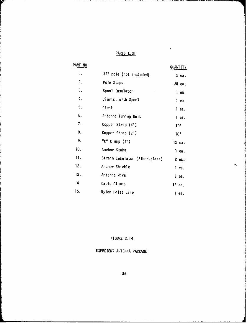
PARTS LIST
PART NO. QUANTITY
1. 35' pole (not included) 2 ea.
2. Pole Steps 30 ea.3. Spool Insulator I ea.
4. Clevis, with Spool 1 ea.
5. Cleat 1 ea.
6. Antenna Tuning Unit 1 ea.
7. Copper Strap (4") 10'8. Copper Strap (2") 10'
9. "C" Clamp (1") 12 ea.
10. Anchor Stake 1 ea.11. Strain Insulator (Fiber-glass) 2 ea.
12. Anchor Shackle 1 ea.
13. Antenna Wire l ea.
14. Cable Clamps 12 ea.15. Nylon Hoist Line I ea.
FIGURE B.14
EXPEDIENT ANTENNA PACKAGE
86
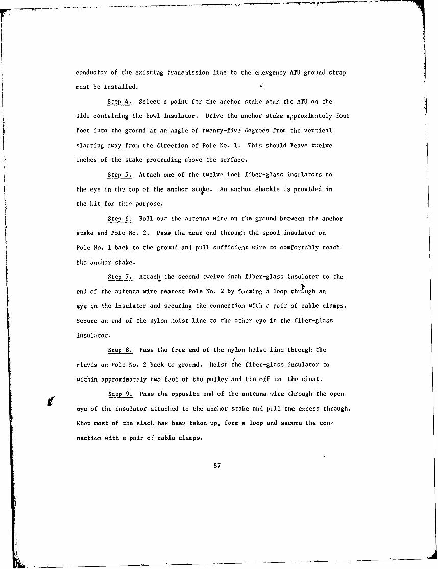
conductor of the existiug transmission line to the emergency ATU ground strap
must be installed.
Step 4. Select a point for the anchor stake near the ATU on the
side containing the bowl insulator. Drive the anchor stake approximately four
feet into the ground at an angle of twenty-five degre2es from the vertical
slanting away from the direction of Pole No. 1. This should leave twelve
inches of the stake protruding above the surface.
Step 5. Attach one of the twelve inch fiber-glass insulators to
the eye in th-2 top of the anchor stake. An anchor shackle is provided in
the kit for t-19. purpose.
Step 6. Roll out the antenna wire on the ground between the anchor
stake and Pole No. 2. Pass the near end through the spool insulator on
Pole No. 1 back to the ground and pull sufficient wire to comfortably reach
th- anchor srake.
Step 7. Attach the second twelve inch fiber-glass insulator to the
end of the antenna wire nearest Pole No. 2 by forming a loop through an
eye in the insulator and securing the connection with a pair of cable clamps.
Secure an end of the nylon hoist line to the other eye in the fiber-glass
insulator.
Step 8. Pass the free end of the nylon hoist line through the
clevis on Pole No. 2 back to ground. Hoist the fiber-glass insulator to
within approximately two fae of the pulley and tie off to the cleat.
Step 9. Pass the opposite end of the antenna wire through the open
eye of the insulator attached to the anchor stake and pull the excess through.
When most of the slack has been taken up, form a loop and secure the con-
nection with a pair o' cable clamps.
87

Step 10. Return to Pole No. 2, loosen the hoist line and draw
additional slack out of the wire until not more than a two foot sag remains
at the midpoint between the poles. At this point the fiber-glass insulator
bhould have been drawn close to the clevis spool at the top of Pole No. 2.
If the insulator jams in the clevis before the wire pulls taut or, con-
verbely, if the wire pulls taut before the fiber-glass insulator is within
a foot. or two of the clevis, slack the hoist line, make an appropriate length
adjustment at the an-hor stake end of the antenna wire and re-tighten. When
the antenna wire has been properly adjusted for length and sag, tie the
hoist line off to the cleat arid trim off the excess wire at the anchor
stake connection. Additional sag which nay occur during operation may be
removed by further adjustment of the hoist line.
Step 11. Connect the center shaft of the bowl insulator to the
antenna wire. This connection should be made above and within two feet
of the fiber-glass insulator. The lead should be kept as 1hort as possible.
A two inch copper strap has been provided for fabrication o,: the lead.
B.2.4 HATCHING IN
St 1. Adjust the transmitter for the lowest power output and
apply power to the emergency antenna, narrier only. Tune the transmitter for
best operating ccnditions, record the antenna current indicated by the base
current ammeter in the emergency antenna tuning unit and turn off the trans-
mitter. Open the emergency antenna tuning unit and movc the tap on the spries
coil one turn in either direction. Close the ATU, turn on the transmitter and
again note the antenna current. if the antenna current has increased con-
tinue to adjust until maximum antenna current has been achieved. Should
88
the current decrease upon the first adjustment reverse direction and adjust
for maximum antenna current.
Step 2! When maximum antenna Lurrent has been achieved re-tune the
transmitter for besc operation and increase power to the normal level. If
the transmitter behaves in a normal or near normal manner and is capable
of being modulated normally no further adjustment of the ATU is required
and emergency operations may be initiated.
Step 3. Should the transmitter not behave normally further adjustment
is required. TuutA the transmitter off and re-adjust for lowest practical
power output. Move the tap on the ATU shunt coil one turn in either dir-
ection and adjust for maximum antenna current as described in Step 2. Turn
on the transmitter and check tuning conditions. If conditions have been
improved continue to adjust the shunt coil gradually, until best operating
conditions have been attained. Adjustments in the series coil will be
necessary during the shunt adjustments to maintain antenna current. As
a rule of thumb, a turn added to ane will result in the necessity to remove
a turn fron. the other.
89
rI
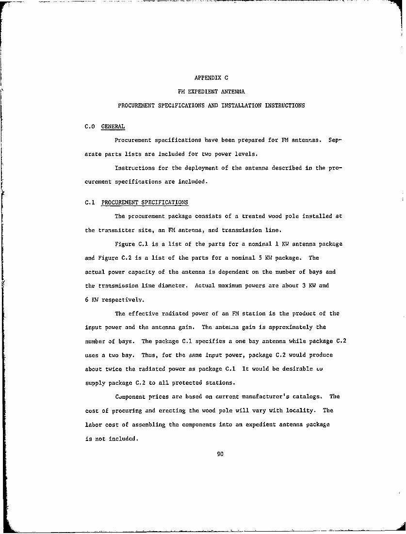
APPENDIX C
FM EXPEDIENT ANTENNA
PROCURBENT SPECIFICATIONS AND INSTALLATION INSTRUCTIONS
C.O GENERAL
Procurement specifications have been prepared for FM antennas. Sep-
arate parts lists are included for two power levels.
Instructions for the deployment of the antenna described in the pro-
curement specifications are included.
C.1 PROCUREMENT SPECIFICATIONS
The procurement package consists of a treated wood pole installed at
the transmitter site, an FM antenna, and transmission line.
Figure C.1 is a list of the parts for a nominal 1 KW antenna package
and Figure C.2 is a list of the parts for a nominal 5 KW package. The
actual power capacity of the antenna is dependent on the number of bays and
the transmission line diameter. Actual maximum powers are about 3 KW and
6 KW respectivelv.
The effective radiated power of an FM station is the product of the
input power and the antenna gain. The antei.na gain is approximately -the
number of bays. The package C.1 specifies a one bay antenna while package C.2
uses a two bay. Thus, for the same input power, package C.2 would produce
about twice the radiated power as package C.1 It would be desirable tu
supply package C.2 to all protected stations.
Component prices are based on current manufacturer's catalogs, The
cost of procuring and erecting the wood pole will vary with locality. The
labor cost of assembling the components into an expedient antenna package
is not included.
90
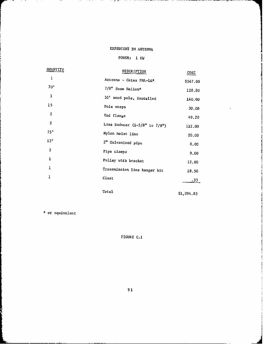
EXPEDIENT Mk ANTENNA
POWER: 1 KW
QUANTITY DESCRIPTION COST
1 Antenna - Gates FMA-lA* $567.00
70' 7/8" Foam Hleliax* 128.80
1 35' wood pole, installed 140.00
15 Pole steps 30.00
2 End flange 49.20
2 Line Reducer (1-5/8" to 7/8") 112.0075' Nylon hoist line 20.00
12' 2" Galvanized pipe 8.00
2 Pipe clamps 9.00
1 Pulley with bracket 12.001 Transmission line hanger kit 18.50
1 Cleat .35
Total $1,094.85
* or equivalent
FIGURE C.1
91
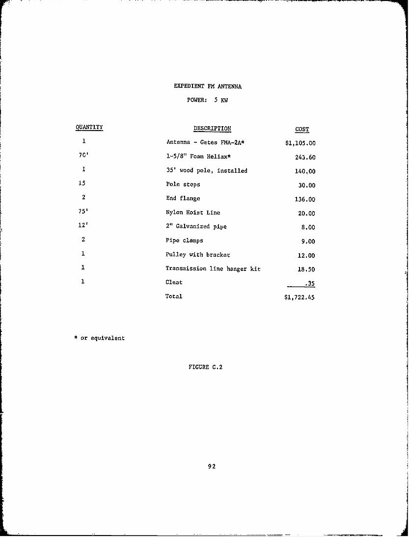
EXPEDIENT FM ANTENNA
POWER: 5 KW
QUANTITY DESCRIPTION COST
1 Antenna - Gates FMA-2A* $1,105.00
70' 1-5/8" Foam Heliax* 243.60
1 35' wood pole, installed 140.00
15 Pole steps 30.00
2 End flange 136.00
75' Nylon Hoist Line 20.00
12' 2" Galvanized pipe 8.00
2 Pipe clamps 9.00
1 Pulley with bracket 12.00
1 Transmission line hanger kit 18.50
1 Cleat .35
Total $1,722.45
* or equivalent
FIGURE C.2
92

C.2 INSTALLATION INSTRUCTIONS: FM EMERGENCY ANTENNA
C.2.1 GENERAL
This emergency antenna kit contains, with the exception of the
support pole, the complete assortment of hardware and materials necessary for
the deployment of a usable emergency F4 antenna. The emergency antenna will
consist of a standard single bay 11/ antenna for transmitter power outputs
up to 1 KW or a two-bay antenna for powers from 1 KW up to 5 KW and suf-
ficient transmission line withi fittings to couple the antenna to the trans-
mitter.
Deployment will be accomplished in two phases; Preliminary
Preparation and Emergency Deployment. Preliminary Preparation is to be
carried out as soon as the kit is received and will consist mainly of pro-
curing and installing the support pole, pole steps, antenna mounting brackets
and transmission line hangers. Emergency Deployment will be carried out only
after the original antenna has been damaged beyond use and will consist
principally of installing the emergency FM antenna and transmission line.
The following installation instructions are of necessity broad in
application because of the great variety of conditions which exist at
individual FM broadcast stations. It is anticipated, however, that given the
materials and these limited instructions the average radio technician will be
capable of placing his FM station back on the air to offer at least partial
coverage to his normal service area. The goal is to restore service within
thirty minutes.
Figure C.3 is a drawing of the two-bay expedient antenna, showing
installation details. Reference to this drawing should be helpful in deploy--
ment of the single or two-brw i~t.
93

AI
SIMt~OTCE.L E ~'JE~ IE7 Af (I KVJ) Wlt.L MO%
13/' tA, FLAIWC;*C
* ~~~O TRA.,JCMiccIN LIN~E 1 -GE
_-1L~S4A Gj
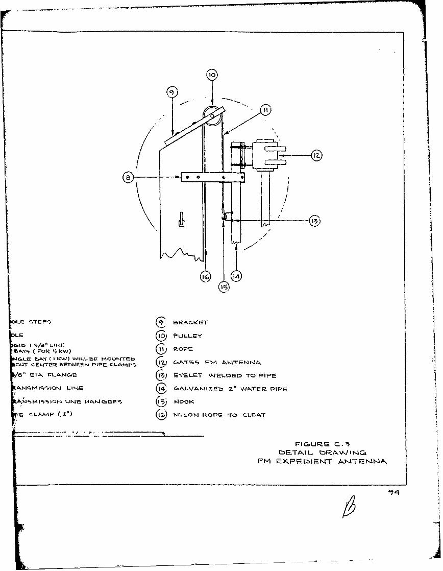
LrEcT~= C9r~~ ERACIcGT
LE 10PULLe
C.IIM 15/80 Llt.IE ROPE154MC (FOR 5 ICW) 0
GL tokY (I KW) WIltL MEZ MOUNTE)GITEFOUT CENTER BETWJEEN PIPE Cl-AMPS ~I'C, AE' -)N~
/8" EA PLAWNCiECv EYELET 'NELMED TO PIPE
ANASICCPIOK1 LINS4 C14GALVAMIZr~t -Z WA4TE9. PIPE
rz :LA.~MP- I.Z'.L-ow ROPS To C.LFA.T
FI CZsLRE c..'5
FM rXKPr-.toIFNT T4~A

C.2.2 PRELIMINARY PREPARATION
Step 1. Procure a treated, thirty-five foot wooden pole and the
services of a local contractor to set the pole upright in the ground.
Step2 2. Starting ten feet from the butt end install a total of
eight pole steps along one side at three foot intervals. Starting eleven feet
six inches from the butt install seven pole steps at three foot intervals
along the opposite side. This will provide staggered steps eighteen inches
apart.
Step 3. Install the pulley with bracket on the tip end of the pole
as shown in Figure C.3.
Step 4. Install one of the pipe clamps twelve inches from the tip
end of the pole. Install the second pipe clamp five feet below the first
for a single bay antenna. For a two-bay antenna measure the distance separa-
tion bet-reen the bays and install the second pipe clamp below thu first, the
distance separation les. two feet.
Step 5. Install the transmission line hangers in accordance with
directions in the hanger kit.
Step 6. Set the pole near the transmitter so that the seventy feet
of transmission line in this kit will suffice. Setting depth is five feet.
Step 7. Install the cleat approximately fve feet above ground.
Step 8. Install the end flanges on the transmission line and in
the case of the sing:e bay antenna also install the line reducer units to
adapt the smaller line to the antenna and transmitter connections.
Step 9. Assemble the FM antenna on the two inch galvanized pipe,
aligning the top bay of the two-bay antenna with the top end of the pipe.
95
Assemble the single bay antenna approximately eighteen inches below the
top end of the pipe. Store tae antenna and transmission line in a secure
place. This completes preliminary preparation.
C.2.3 EMERGENCY DEPLOYMENT
Step 1. Lay out the transmission line on the ground at the base of
the pole and attach one end to the antenna connection.
Step 2. Make one end of the hoist line fast to the eye on the
galvanized pipe and pass the free end through the pulley at the top of the
pole.
Step 3. Hoist the antenna into position and tie off the hoist line
to the cleat.
Step 4. Clamp the galvanized pipe in the pipe clamps previously
installed on the pole.
Step 5. Connect the free end of the transmission line to the trans-
mitter.
96
APPENDIX D
EXPEDIENT ANTENNA CONSTRUCTION
D.O GENERAL
The purpose of this monograph is to describe techniques useful in
the construction of an expedient AM antenna system under emergency con-
ditions. It is assumed that the normal antenna has been destroyed during
an emergency and that no pre-packaged emergency antenna is available. The
station's technician Is to restore limited service using only parts and
teols as may be available.
The basic steps in restoring service are damage assessment, physical
construction, adjustment, and operation. Each of these steps is critical
to restoring maximum service in the shortest possible time. Time is more
important than radiated power, so an inefficient operation in 15 minutes
is betLer than full power in two hours.
D.1 DAMGE ASSESSMENT
The first step is to discover how much of the antenna system has
been destroyed. Presumably a tower has fallen. If you have a directional
antenna system and one of the towers is intact, use it as a non-directional
antenna. It will be a better expedient antenna than any antenna you can
construct in a short time.
Check the antenna tuning unit and the transmission line. A tuning
unit will be necessary to couple to the antenna. If the normal unit is
not severely damaged, it can be used. If it is damaged beyond use, salvage
any components that may be useful to build another tuning unit.
97
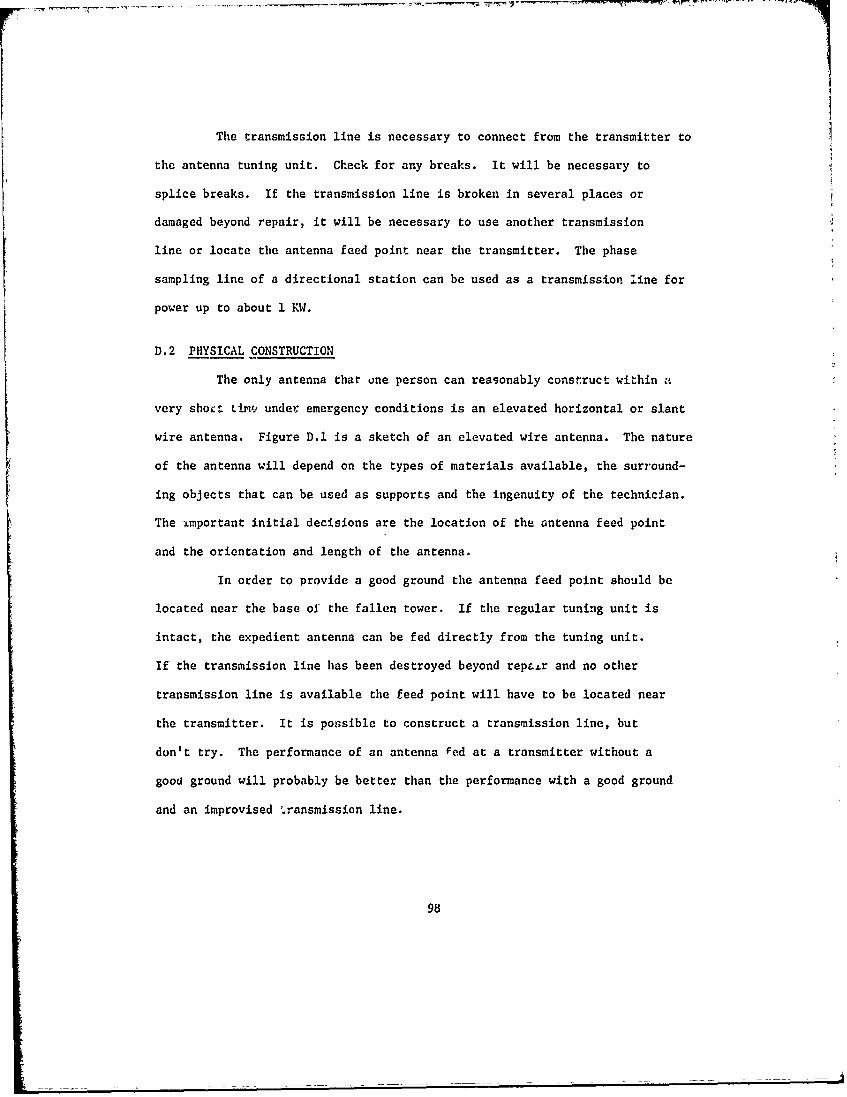
The transmission line is necessary to connect from the transmitter to
the antenna tuning unit. Check for any breaks. It will be necessary to
splice breaks. If the transmission line is broken in several places or
damaged beyond repair, it will be necessary to use another transmission
line or locate the antenna feed point near the transmitter. The phase
sampling line of a directional station can be used as a transmission line for
power up to about 1 KW.
D.2 PHYSICAL CONSTRUCTION
The only antenna that one person can reasonably construct within a
very sho Li..- under emergency conditions is an elevated horizontal or slant
wire antenna. Figure D.1 is a sketch of an elevated wire antenna. The nature
of the antenna will depend on the types of materials available, the surround-
ing objects that can be used as supports and the ingenuity of the technician.
The important initial decisions are the location of the antenna feed point
and the orientation and length of the antenna.
In order to provide a good ground the antenna feed point should be
located near the base of the fallen tower. If the regular tuning unit is
intact, the expedient antenna can be fed directly from the tuning unit.
If the transmission line has been destroyed beyond repai.r and no other
transmission line is available the feed point will have to be located near
the transmitter. It is possible to construct a transmission line, but
don't try. The performance of an antenna Fed at a transmitter without a
good ground will probably be better than the performance with a good ground
and an improvised .ransmission line.
98
CLoUi T :2
ILI
0
99U
The ideal orientation of the antenna is broadsidi to the area you
need to serve, however, if supporting structures are readily available-
for other orientations do not waste time building new supports. You can
always construct a better antenna after restoring some service.
The first choice for the length of the enpedient antenna is the
height of the regular antenna. The input impedance of the expedient
antenna will be almost identical to the impedance of the regular antenna
and the regular antenna tuning unit can be used with little or no adjustment.
If the regular antenna is taller than one quarter wavelength and it
is not possible to support a horizontal wire antenna as long as the regular
antenna then construct a quarter wavelength antenna. Figure D.2 shows the
length versus frequency for t quarter wavelength.
The availability of supporting structures will to some extent deter-
mine the length and orientation of the expedient antenna. Use any existing
structures available such as trees, buildings, and utility poles. A step
ladder or even an automobile can be useid if nothing else is available.
The antenna proper consists of a conductor supported on insulators
and fed at one end. The conductor can be almost any wic-. -.en a radial
from the ground system. The wire size should be at least #14 to carry the
current. If it is necessary to use two or more pieces of wire to reach the
desired length, the splices must be good mechanical and electrical connections.
Figure D.3 shows techniques of splicing wires. The splices should be soldered
if possible.
The antenna must be insulated from ground and supporting structures.
The only electrical contact to the antenna is the feed point. Figure D.4
100

500
,400 _
300
I I200 7 --..._
4"4100 - - I
0 r4,00 600 800 1000 1200 1400 1600
FREQUENCY (KHz)
1/4 WAVELENGTH VS FREQUENCY
FIGURE D.2
101
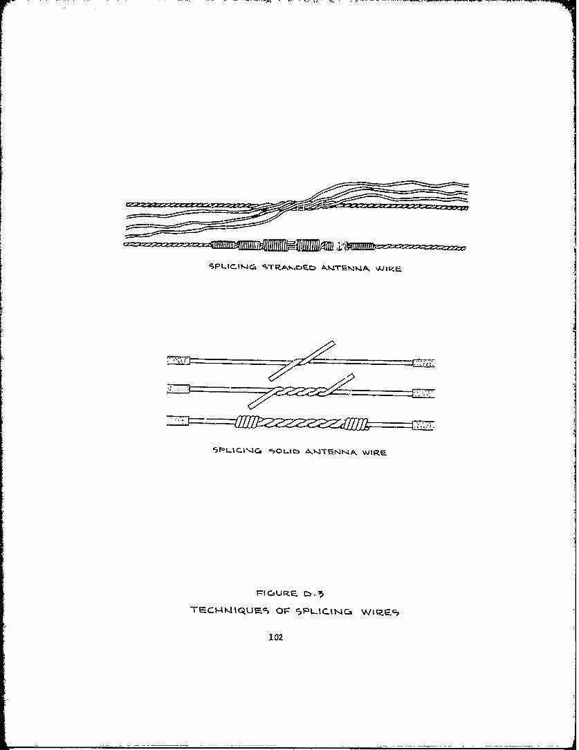
VIR,
TF-C.l4IjUE-c, OF 5pLjINC4 Wipac,
102
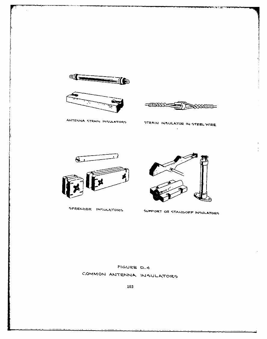
A~NKIA ' IR~N t5ULA^7rOP,, '-TRAIN I.J%ULA,-rolZ (1 c>rrL WIrr
103
shows techniques for using several types of common insulators. An insulator
can be improvised from almost any plastic or nylon material. An empty
soft drink bottle makes an excellent insulator. If nothing else is
available dry wood can be used. Figure D.5 shows several improvised insula-
tors.
An antenna tuning unit is usually necessary to couple to the antenna.
If the regular tuning unit is usable, use it. If the regular unit is
unusable, construct an L network. Figure D.6 is a sketch of an L network
used as an antenna tuning unit nn" Figure D.7 is a tabulation of the approxi-
mate initial adjustment of the coils.
D. 3 ADJUSTMENT
The an'tenna tuning unit should be adjusted to match the transmitter
to the antenna as well as possible. If an RF impedance bridge is available,
measure the input impedance to the antenna tuning unit and adjust the coils
to produce the best match possible.
Without an impedance bridge, the antenna tuning unit is adjusted to
produce the maximum antenna current. Reduce the transmitter output power
to a minimum and proceed with the following steps:
a. Turn on power and observe antenna current.
b. Turn off transmitter and move L2 one turn.
c. Repeat a and b until maximum current is achieved.
d. Turn off transmitter and move L one turn.3
e. Turn on transmitter and observe antenna current.
104
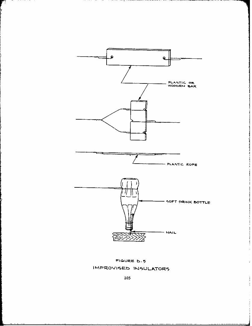
PLVSlC PROPEI
- SOFT 143RINK ISO-rTLC-
NAIlL
FICISURE b:.~
IM'ROVIb C)LA:OR
105
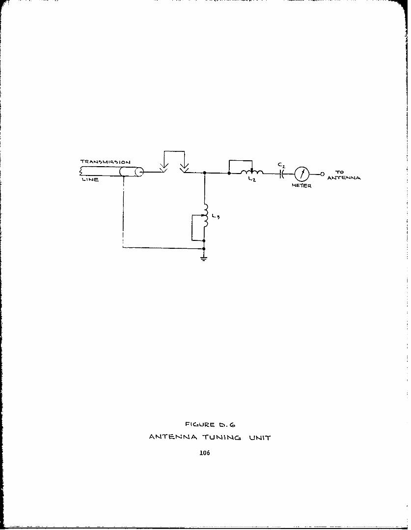
L3
I GURF nTTumittO, um-
106> T
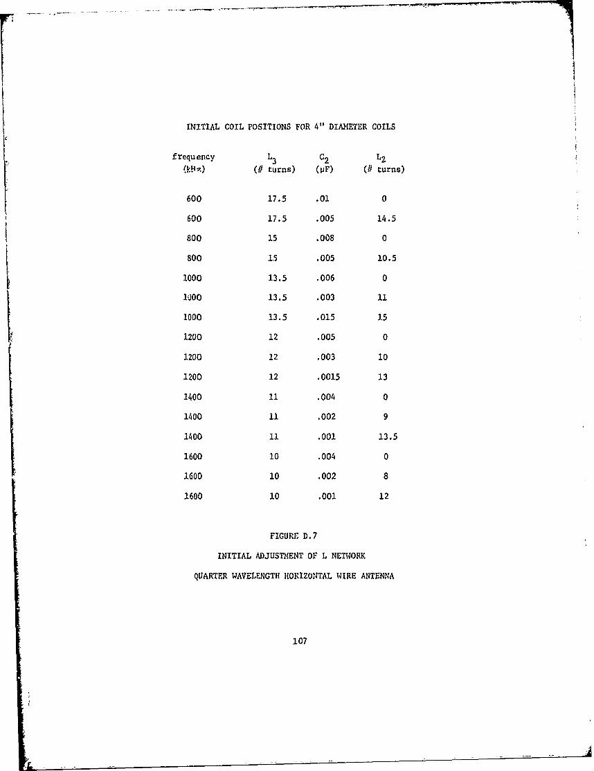
INITIAL COIL POSITIONS FOR 4" DIAMETER COILS
frequency L3 C2 L2
(k( turns) (IF) (# turns)
600 17.5 .01 0
600 17.5 .005 14.5
800 15 .008 0
800 15 .005 10.5
1000 13.5 .006 0
1000 13.5 .003 11
1000 13.5 .015 15
1200 12 .005 0
1200 12 .003 10
1200 12 .0015 13
1400 11 .004 0
1400 11 .002 9
1400 11 .001 13.5
1600 10 .004 0
1600 10 .002 8
1600 10 .001 12
FIGURE D. 7
INITIAL ADJUSTMENT OF L NETWORK
QUARTER WAVELENGTH HORIZONTAL WIRE ANTENNA
107
f. Repeat d and e until maximum current.
g. Repeat a through f until maximum current.
h. Re-tune transmitter and increase power as much as practical.
0.4 OPERATION
The operation of the expedLent antenna is more critical than the nor-
mal antenna. Since tie antenna is improvised it is readily subject to
damage. The antenna should be inspected frequently. Since the transmitter
is operating under abnormal conditions, the transmitter parameters should
be monitored continuously to prevent damage.
If the emergency is not national, the Federal Communications Com-
mission should be notified of the improvised operation as soon as practical.
The broadcast of emergency information, however, takes precedence over
requirements to notify the FCC.
After service is restored using the expedient antenna, the possi-
bility of improving the efficien:y of the antenna should be considered. The
major improvement possible is to increase the height of the antenna above
the ground. The higher the antenna, the stronger the radiated signal.
108