AD 259 904 · · 2013-10-15unclassified ad 259 904 reproduced luf, the armed services technical...
43
UNCLASSIFIED AD 259 904 Reproduced luf, the ARMED SERVICES TECHNICAL INFORMATION AGENCY ARLINGTON HALL STATION ARLINGTON 12, VIRGINIA ÜFCLASSIFIED
Transcript of AD 259 904 · · 2013-10-15unclassified ad 259 904 reproduced luf, the armed services technical...
UNCLASSIFIED
AD 259 904 Reproduced
luf, the
ARMED SERVICES TECHNICAL INFORMATION AGENCY ARLINGTON HALL STATION ARLINGTON 12, VIRGINIA
ÜFCLASSIFIED

r-
NOTICE: Vihen government or other drawings, speci- fications or other data are used for any purpose other than in connection with a definitely related government procurement operation, the U. S. Government thereby incurs no responsibility, nor any obligation vhatsoever; and the fact that the Govern- ment may have formulated, furnished, or in any way supplied the said drawings, specifications, or other data is not to be regarded by implication or other- wise as in any manner licensing the holder or any other person or corporation, or conveying any rights or pennission to manufacture, use or sell any patented invention that may in any way be related thereto.

BLANK PAGES IN THIS DOCUMENT WERE NOT FILMED

n
it
co >~ CD
CD
o ̂
f
'III
liBlli
I*
""j Ivll
MEMORANDUM REPORT NO. 1347 MAY 1961
A DOUBLE-CHARGE TECHNIQUE TO MEASURE
FACE-ON BLAST
C
W. Olson J. Wenig
j
\ o*
A S TIÄ
M JUL24 1961 f J
TIPDR
^
Department of the Army Project No. 503-04-002 Ordnance Management Structure Code No. 5010.11.815
BALLISTIC RESEARCH LABORATORIES ',..,I.liV■■^^..■:A.^W^■..|^.^',.^-.'^...■,.V.^.l<■■^;^■■■-^^.,^,-,^hV■^■^■,■C.V^■:^.^■-.■.^f .<■••■.,■./.■./.•..^^.l.^.s ..:^^.-i.lV^-^..A-.^....<..,M>\<.-j>-i-ip^.t>^-J ..£- A-
ABERDEEN PROVING GROUND, MARYLAND

ASTIA AVAILABILm NOTICE
Qualified requestors may obtain copies of this report from ASTIA.
BALLISTIC RESEARCH LABORATORIES
MEMORANDUM REPORT NO. l^Y
MAY 1961
A DOUBLE-CHARGE TECHNIQUE TO MEASURE FACE-ON BLAST
W. Olson
J. Wenig
Terminal Ballistics Laboratory
Department of the Army Project No. 505-0^-002 Ordnance Management Structure Code No. 5010.11.815
ABERDEEN PROVING GROUND, MARYLAND
TABLE OF CONTENTS
ABSTRACT.
INTRODUCTION
PHYSICAL TEST SETUP . . .
INSTRUMENTATION
EXPERIMENTAL PROCEDURE. .
COMPUTATIONAL PROCEDURE .
RESULTS AND DISCUSSION. .
CONCLUSIONS .......
REFERENCES
APPENDIX A. ...... .
APPENDIX B
DISTRIBUTION LIST ....
B 9 ■ • •
Page
3
5
6
6
13
17
19
2k
25
27
29
35
■

BALLISTIC RESEARCH LABORATORIES
MEMORANDUM REPORT NO. 15^
WCOlson/jWenig/bjk Aberdeen Proving Ground, Md, May 1961
A DOUBLE CHARGE TECHNIQUE TO MEASURE FACE-ON BIAST
ABSTRACT
Thla report presents measurements of air blast parameters at the
midpoint of a line joining two equal weight explosive charges. The
explosive used was 50/50 Pentolite with dual one or eight-pound spheres
being detonated simultaneously. The pressure transducer employed was
a BRL "pancake" pressure gage employing a synthetic piezoelectric
ceramic as the sensing element. Pressure, impulse and duration measure
1/3 ments were obtained for scaled distances of 1.5 to 3-2 ft/lb ' for
comparison with data derived by other techniques.

INTRODUCTION
1 2* In studying the response of targets ' to the transient loads of air
blast, two parameters of interest are the peak overpressure and positive
impulse associated with the blast wave. Peak pressure and impulse usually
are designated as either "side-on" or "face-on." Side-on (or hydrostatic)
pressure and impulse can be measured by a transducer whose sensing element
is parallel to the direction of propagation of the wave. Face on (or dynamic)
pressure and impulse are usually measured by a sensing element which forms
part of a large rigid surface situated normal to the incident blast wave.
Face-on blast experiments at the BRL consist primarily of measurements
of pressure-time histories with piezoelectric gages flush-mounted in a large
reflecting surface and subjected to air blast at normal incidence, or of
measurements of impulse only with a mechanical gage consisting simply of a
moveafcuLe plug mounted in the surface .
Each of the above experimental methods can have limitations. In the
case of flush-mounted gagea, it is difficult to calibrate the gage directly.
Calibrations are obtained indirectly by measurements of incident shock
velocities. From these incident velocities, the incident pressure is
determined from the Rankine-Hugoniot relationships. Then a theoretically k
determined ratio of incident to reflected shock pressures is applied .
Furthermore, at small distances from the explosive, shock loadings by the
blast may exceed the mechanical performance capabilities of the gage and
hence result in a distortion of the response. The mechanical or plug
method can only be used to measure face-on impulse. The quantity which
it measures may be positive impulse, total impulse, (i.e., positive less
negative), or some intermediate value depending on the mass of the plug
and the duration of the blast wave.
It has long been realized that the face-on reflection of a blast wave
from a rigid surface can be simulated by the simultaneous detonation of two
Identical explosive charges. The plane lying midway between the charges
can represent a rigid surface. In fact, a model often used to describe the
* Superscript numbers denote references listed at the end of the report,
:

reflection process is depicted in Figure 1, where a "virtual charge"
replaces the reflecting surface . It is the purpose of this report
to discuss some results obtained with a piezoelectric gage placed at the
geometric center of two identical explosive charges which were detonated
simultaneously, and to compare these data with data from the other methods.
PHYSICAL TEST SETUP
A pre-calibrated side-on piezoelectric gage was placed at the midpoint
of a line joining the centers of two equal weight explosive charges (Fig. 2).
Pairs of one or eight-pound spherical charges of cast 50/50 Pentolite were
used for the experiments. The charge pairs were simultaneously initiated hy
an electronic circuit which applied a 5000-volt pulse to the "Engineers
Special" electric detonators centrally located in the explosive spheres
(see Fig. 5)•
INSTRUMENTATION
Simultaneity of detonation of the pairs of explosive charges was
achieved hy means of an electronic circuit described in detail in Appendix I.
A separate identical power supply, of low impedence, was used for each
charge. Both supplies were triggered simultaneously by a common input.
The peak voltage output of each supply is approximately five kilovolts.
The energy source is a four micro-farad capacitor switched by means of
a hydrogen thyratron. The pair of pulsed supplies made simultaneous
firing more certain by reducing the possibility of high voltage flash-over
across the lead wires which might have occurred if series or parallel
circuitry were employed.
High speed photographs were taken to check the simultaneity of
initiation of two charges. A commercial electronic shutter based on the
Faraday principle was used. The effective exposure time of the camera
was somewhat less than one microsecond. Figures k, 5, and 6 show the
luminous expanding shock front from dual one-pound charges at approximately
10, 50, and 75 M^sec after initiation and indicate that simultaneity was
achieved. A further check on simultaneity is obtained by observing the
. . . .
ÜJ CO
< X ü
<t üJ
\ /
■R
üJ CD
I O
D
-K- H 0)
•H

in. .>-e M
ÄS' y '
1 ■• •'

bJ
UE
NC
IM
ER
O »- hi (0
s < CQ
\ O 01
•H
QC > LÜ ^ «0
_J m D a.

w
o I—I
10

11

arrival, of two shock envelopes at the (_'at5e aa evidenced In Figures '/ and 8.
Figure 9 is a schematic of the system used to photograph the shocks passing
over the gage. An exploding wire served as the light source and a lens was
used to concentrate the light.
EXPERIMENTAL PROCEDURE
Prior to using the gage for these experiments, it was pre-calibrated
in the following manner. The test gage was bracketed by another pair of
piezoelectric gages which were used to sense time of arrival of an air
blast wave and from which could be determined an average velocity of the
wave over the interval. This average velocity is equivalent to the
instantaneous velocity at the midpoint of the interval. Peak pressure of
the wave could then be inferred from the Rankine-Hugoniot equation which
relates peak pressure with velocity. By comparing the oscillographic
output waveform of the test gage to a series of known calibration steps;
a gage constant for the gage can be obtained. The "gage-constant" or
sensitivity of the gage used in this series of experiments was 2k.k uu
coulombs per pound per square inch of impressed pressure.
Before firing, all Penbolite explosive charges were weighed, and
although found to be very nearly equal to their nominal weights, were
sorted in equal weight pairs. Each pair of charges was then suspended
from an overhead cable (see Fig. 2) and guyed in position so that the
pre-calibrated gage was positioned at the midpoint of the line joining
the charge centers. The charges and gage were aligned by eye, and the
distances from gage center to charge center measured by steel tape to
an accuracy of + 0.01 ft. The electrical detonators were positioned
perpendicular to the ground plane and electrical leads were oriented
to minimize the possibility of metal fragments from the detonators and
lead wires from, striking the gage. The signal generated by the gage
was displayed and recorded via an amplifier and cathode-ray tube system
and recorded by a General Radio streak camera (modified to produce film
speeds of the order of two Inches per millisecond).
13

SHOCK FRONTS
ik

15
tu o a =5 O
I o
Lü
o z ö o -J a. x
a. x Ul
16

By this procedure, we obtained acceptable oscillograras at several
scaled distances in to 1.5 ft/lb ' ^ from both charge weights used in
these experiments. Figure 10 shows such an oscillogram recorded by
detonation of a pair of one-pound charges at a scaled distance of
1,5 ft/lb ' , It indicates that acceptable pressure-time histories 7
can be obtained at the limit of Hoffman & Mills data.
COMPUTATIONAL PROCEDURE
Fifteen pressure -time histories were obtained from one-pound charges at
scaled distances of 5-52, 5-0; 2.5 and 1.5 ft/lb ' . In addition, two
check rounds were fired using eight-pound charges at a scaled distance of 1.5
Peak overpressure, positive impulse, and positive duration were measured
from these oscillograms.
With individual gage KA's (gage sensitivities) established, peak
overpressure was calculated from
P - ä x i. V S X KA
where
P = peak overpressure, psi,
H = height of initial peak of pressure-time history on the film record.
S = voltage calibration step size on the record.
Q = calibration charge, |i|i coulombs.
Heights H and S were measured by an arbitrary scale of the individual film
records.
Positive impulse is defined as
rT
p(t)dt
0
where p(t) is the overpressure as a function of time t and T is the duration
of the positive phase. Integrating numerically we obtain
T = M x Q KA x US
17


where I = positive reflected impulse, pslms.
M = area under the positive phase of the pressure-time history.
U = time scale factor, scale units/ms.
The area under the positive phase of the pressure -time history was
computed by the trapezoidal rule from ordinate measurements on film records
at small equal intervals.
Positive duration is obtained directly from the pressure-time histories
and is defined as the time from the onset of the blast wave until the peak
overpressure first returns to zero and before the pressure enters its
negative phase.
RESULTS AND DISCUSSION
i t
Table I presents a re.'jurae of the data. Figure 11 indicates that the
data of Table I are consistent with reflected pressure data from BRL Report 7
No. 988 and reflected pressures inferred from the velocity data of BRL #8
S&k . The reflected impulse data are compared with data from BRL 988 and
BRIM IO88 in Figure 12. It is apparent from these figures that the
proc.Uiion of our experiments is at least as good as the precision of the
other methods. Our data were also consistent with and included in a 9
compilation of experimental results from various sources in BRL 1092 .
1/3 Figure 15 displays a record at Z = 3'52 ft/lb ' from two blast
waves which did not meet at the center of the gage. The initial portion
of the pressure -time history shows the pressure impojed on the gage by a
single charge. The pressure, 91-2 psi, agrees with incident pressures for
this .;caled distance inferred by other methods. A short time later the
pressure is quickly modified to give a pressure which corresponds to the
pressure at a short distance away from a reflecting surface. This pressure
* Reflected pressures were established from the incident pressures of BRL Report No. 98^ by using the tables of pressure ratios, Preflected/Pincident, of the reflected shock wave versus the pressure ratio Pincident/Patmos pheric of the incident shock wave for normal reflections in air in Refer- ence 10.
19

! "^ 1
LU CO
CO o.
CSl
CSJ ro o>
— —• ■< o UJ as J ftg i
»— o 5 ^ Uba P—
CO »— * '< c» *• 1 <J *-» UJ ca Hi ae ^ UJ B?
UJ »- 4^ « «e «^
t— to to _ o> CJ eo 1 ■«- IO f— CSJ r— «"■ IO
a> ot a 0 CVJ ro CSJ ro ,»" IO to •*- a> CM ro ro ro ro «r IO <*• «tf IO ^r •»■ u. «c
—I -<
1 5 o o c; 1 : UJ
i "* * ae UJ
i UJ ac • •C w ^ => J ^- ^ 1 c
UJ ; o UJ 2C « ^ 1 SE OC O O —1
UJ =s ! ^c o_ h- —i a. \ DC CO — CO ao U3 LO 03 r— r^- ao * CD *»• CO o ^J- 13 ro' in CO «^ O <=» o IO r— CSJ ao _ ao ro i i
CSJ CM o r— e» eo CO IO «o- «ti- ro "' ro •a- UJ UJ 1 __ j o o
O LU ^3M
i D5 to
-U ■c «c ■< ae CJ 1 CO CO
CO 1 z — pi
o UJ i 2 —
IIU S w
| CO c»
CO »1 —'S u. r- <M m ro o> ^ «! UJ UJ
C9 SB Q_ ^ ..? ro eo evi »>- h— to O) eo ro o r— eo o IO
P UJ
lO ro
CO ro IO <*■ V o> lO «*■
CSJ CD ro
to ro
to ro
o» ro
o
a - t * o
LU r— »— «c 0- o <-> oe 1- LU UJ
1 UJ -
«=> UJ
LU -J ^^ —1
OS
UJ * o CSJ CSJ CSJ CSJ CSJ CSl CSJ CSJ CSJ 5 ^
23 LU
\n ir> IO ro ro ro ro o ro PO ro PO ro ro ro PO ro 1— CJ
■^
" *~" CVJ tsj cvi csj ro ro ro ro ro ro ro rri ro PO UJ ac
ae. *s.
<-* at to rw CO S s
1— 0
UJ =E
LU uj i OC C» «; •« CO
»— aE
CO SB JJJ
LU <-> IE as »— ao eo — MM — » — — — *» —
■"" — -^ — — — | e »-
a.. «= u. o
cs LU 1—
S UJ
5 * ! as 1
CO UJ UJ
ac LU I _J
LU
c; [ 0 . .
OC C3 ! ae
eo to m
ro to
to r— CVI
oo Cvl CSJ
o r—
CSJ ro »r oo Oi o CSJ <f> r— oo
o u; a: a: CO C9
= k P K ) K * 1 r K > K j * *
20
.
REFLECTED PRESSURE VS. SCALED DISTANCE
7000
6000
5000
4000
KEY; O DOUBLE CHARGE DATA
a BRL 984 (OPTICAL METHOD)
O BRL 988 (PIEZOELECTRIC GAGE DATA)
NOTE: VERTICAL HEIGHT OF GEOMETRIC
FIGURE REPRESENTS ±1 STANDARD
DEVIATION AND NUMBER OVER
FIGURE REPRESENTS SAMPLE SIZE
SCALED DIST Z» R ^ FT WV LB1"
Figure 11
21

SCALED REFLECTED IMPULSE VS. SCALED DISTANCE
300r
74
200
KEY: A BRL MlOSe (MECHANICAL METHOD)
O BRL 988 (PIEZOELECTRIC GAGE DATA)
O DOUBLE CHARGE
NOTE: VERTICLE HEIGHT OF GEOMETRIC
FIGURE REPRESENTS ±1 STANDARD
DEVIATION AND NUMBER OVER FIGURE
REPRESENTS SAMPLE SIZE
SCALED DISTANCE Z' —^' —.„ W,/» LB"*
Figure 12
22
w p Ü
23

is approximately face-on pressure for this scaled distance. Rds 7 and 8
of Table I give predicted side-on pressure and impulse due to only one of
the two matched pairs being detonated.
CONCLUSIONS
In this report, we have shown that we can obtain a satisfactory
simulation of reflection of a blast wave from a rigid wall by simultaneous
detonation of identical explosive charges. We have measured the pressure-
time histories of the colliding waves using gages which were developed for
side -on blast experiments, and have shown that these measurements agree with
data obtained by other techniques. The data presented here constitute the
first direct measurements with calibrated gages; of the pressure-time history
1/5 of a face-on blast at scaled distances as small as Z = 1.5 ft/lb ' .
iJ. VJ^U^W
W. OLSON
J. WENIG
2i|

REFERENCES
1. Mills, S. and Locklin, R. "Dynamic Response of Thin Beams to Air Blast", BRL Report No. 787, September 1951, Unclassified.
2. Ballard, R., Hoffman, A., and Baker, W. "An Experimental Investigation of the Effects of Motion of A B-29 Horizontal Stabilizer on External Blast Damage", June 1956, Confidential.
3. (a) Johnson, 0., Patterson, J., and Olson, W. "A Simple Mechanical Method for Measuring the Reflected Impulse of Air Blast Waves", BRL Memorandum Report No. 1088, July 1957; Unclassified.
(b) Olson, W., Patterson, J., and Williams, J. "The Effects of Atmospheric Pressure on the Reflected Impulse from Air Blast Waves", January i960, Unclassified.
h, Lampson, C. W. "Resume of the Theory of Plane Shock and Adiabatic Waves with Applications to the Theory of the Shock Tube", BRL TN No. 159, March 1950.
5. "Effect of Atomic Weapons", U. S, Government Printing Office, Washington, D. C.
6. Hinz, D., Wenig, J. "Backlighting the Shock Around a Moving Explosive Charge", BRL Memorandum Report No. 1110, October 1957.
7. Hoffman, A. J., Mills, S. N. "Air Blast Measurements About Explosive Charges at Side-on and Normal Incidence", BRL Report No. 988, July 1956.
8. Sultanoff, M., McVey, G-, "Shock-Pressure at and Close to the Surface of Spherical Pentolite Charges Inferred from Optical Measurements", BRL Report No. 917, August 195^
9. Goodman, H. J. "Compiled Free-Air Blast Data on Bare Spherical Pentolite", BRL Report No. 1092, February i960.
10. Doering, W,, and Burkhardt, G. "Contributions to the Theory of Detonation", (Translation from German prepared by Brown University), Technical Report No. F-TS-1227-1A (GDAMA 9-T-^b), Headquarters, Air Material Command, Wright-Patterson Air Force Base, Dayton, Ohio, May 19^9'
11, Wenig, J. "A Pulse Amplifier for Use with Piezoelectric Velocity Gages", BRL TN No. II58, July 1957-
25

APPENDIX A
Figure 3 iß a block diagram of the field and recording setup. A safety-
firing panel applied a 155-volt positive pulse simultaneously to the grids of
the type 5696 miniature thyratrons (see Fig. Ik), The M30-volt output pulse
of these tubes triggered the hydrogen thyratrons which supplied a 5 K.V. pulse
to the explosive detonators and insured exact and simultaneous output to the
explosive charges. The 5696 tubes were used in preference to the more con-
ventional 2D21 tube since the former exhibit less delay and variation in
firing time. Although the ltC55 tube requires only a 100-volt trigger pulse
to cause it to "strike", a toO volt pulse was used. This combination of 15$
volts applied to the 5696 tube biased at 15 volts, and hOO volts to the grid
of the ^C35j insured exact and simultaneous output pulses to the explosive
charges.
27

-> a
i'iQ1 o
o «o - <M
H
I •H
28

APPENDIX B
DESCRIPTION OF PIEZOELECTRIC GAGE
The blast gage used in these trials was of a type usually used to
measure the side-on blast generated by small explosive charges. The gage
head is in the form of a flat circular disc with beveled edges. It has an
aspect ratio, or the ratio of width to thickness, of over ten to one so as
to minimize perturbations of the shock it measured. The general construction
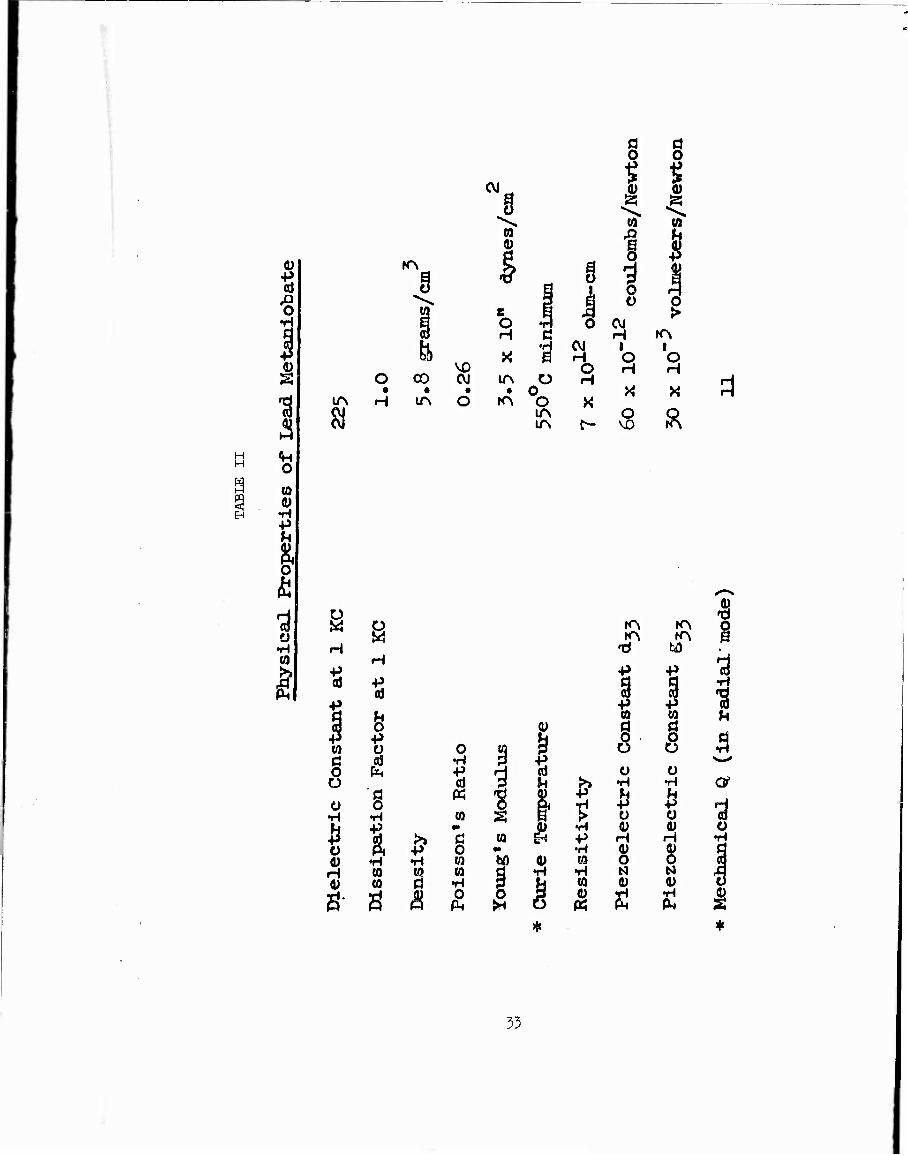
of the gage is shown in Figures 15 through 17. The sensitive piezoelectric
elements used were of lead metaniobate (obtained from the General Electric
Corporation); Table II describes the physical properties of this material.
For blast work, this material possesses some advantages. It has much higher
sensitivity than quartz, or tourmaline. It has a very high Curie point
(550 C), a very low acceleration response, and a low mechanical quality
factor. A low mechanical quality factor, "Q", is desirable in a receiver
transducer and helps to suppress spurious responses as well as providing more
faithful reproduction of the impressed load. The sensing element consisted
of a stack of two piezoelectric discs cemented together, with a silver tab
between them. A small insulated wire was soldered to the silver tab and
drawn through the gage housing and soldered to a coaxial connector at the
stem end. Silicone vacuum grease was smeared around the stack and inside
the gage housing so as to both weatherproof the gage and lo provide good
mechanical coupling between the lead metaniobate and the diaphragm. The
diaphragm was then drawn tightly into place with screws.
29

H
■d
30

U3 H
•H
m rr:
31

■'M
'■'-' 'i?
'ttcmm-
yj:
r-1
•H
O.:. o.:
32
H H
•H
O
(0 0)
•H +>
I 3 •H
Si
g
Hä
I (0
§ Ü
Ü •H
Ü 0) H
KN
u 13
•p
«S
o
•H (0 CO
Ui Ö
CM
O CO CVI • • •
H in O
n- n &
o •H •P
«
(0 •■
fl o 0) •H O
§ § 1 | J., 0) 0)
1 f CO w
a i 1 5
s 1 J Ü g o •H Q CM H C H rA
X CVJ H 'o 'o O H H
IA O H • O « X
K"\ o X lA IA c- 8 Ä
I I (0 !H
W 4) •H
5
•H •P •H (Q
0)
6 rA fA O rA rA B
'd M
P +> •3 g p 1 •H
■3 to CO U d a s 8 a ü ü •H ^H cv ^ h P O
P o ■d
0) 0) o H H •H 4) O 8 N N .3 ID D D
S £ *
33
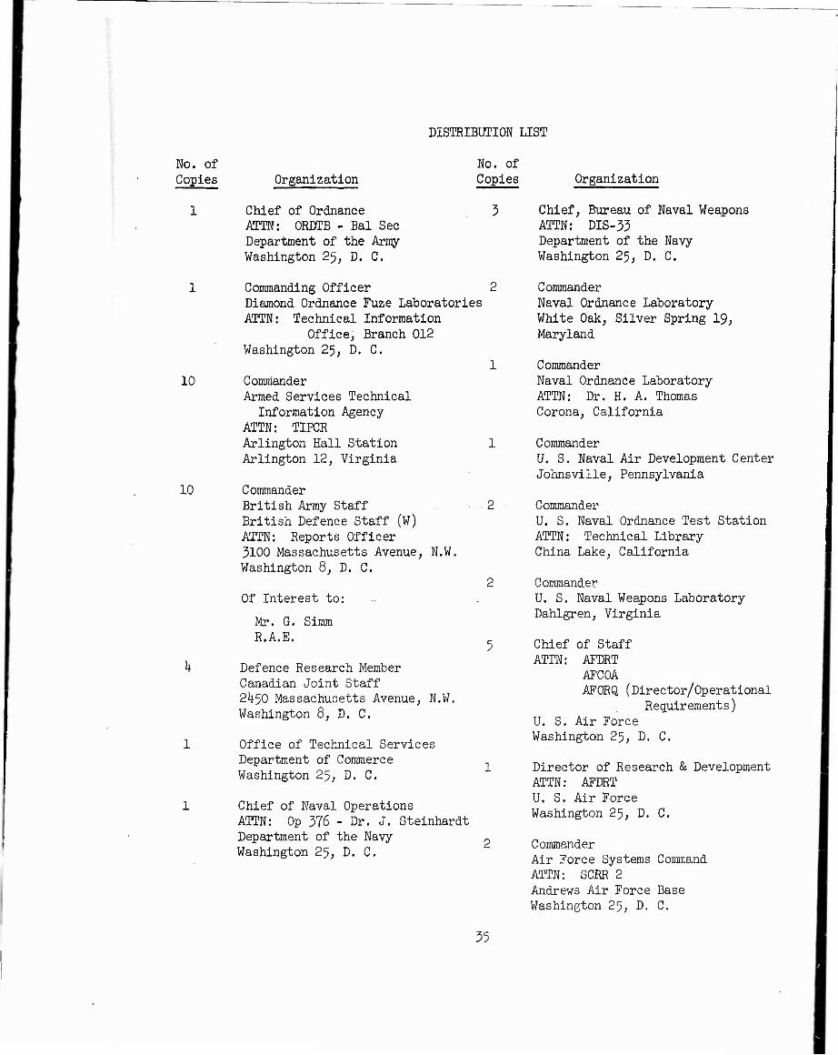
DISTRIBUTION LIST
No. of Copies
No. of Copies
3
10
10
Organization
Chief of Ordnance ATTN: ORDTB - Bal Sec Department of the Army- Washington 25, D. C.
Commanding Officer 2 Diamond Ordnance Fuze Laboratories ATTN: Technical Information
Office, Branch 012 Washington 25, D. C.
1 Commander Armed Services Technical
Information Agency ATTN: TIPCR Arlington Hall Station 1 Arlington 12, Virginia
Commander British Army Staff ■ • 2 British Defence Staff (W) ATTN: Reports Officer 3100 Massachusetts Avenue, N.W. Washington 8, D. C.
2 Of Interest to: ..
Mr. G. Simm R.A.E.
Defence Research Member Canadian Joint Staff 2i)-50 Massachusetts Avenue, N.W. Washington 8, D. C.
Office of Technical Services Department of Commerce Washington 25, D. C,
Chief of Naval Operations ATTN: Op 376 - Dr. J. Steinhardt Department of the Navy p Washington 25, D. C.
Organization
Chief, Bureau of Naval Weapons
ATTN: DIS-33 Department of the Navy Washington 25, D. C.
Commander Naval Ordnance Laboratory White Oak, Silver Spring 19, Maryland
Commander Naval Ordnance Laboratory ATTN: Dr. H. A. Thomas Corona, California
Commander U. S. Naval Air Development Center Johnsville, Pennsylvania
Commander U. S. Naval Ordnance Test Station
ATTN: Technical Library China Lake, California
Commander U. S. Naval Weapons Laboratory Dahlgren, Virginia
Chief of Staff ATTN: AFDRT
AFCOA AFORQ (Director/Operational
Requirements) U. S, Air Force Washington 25, D, C.
Director of Research & Development ATTN: AFDRT U. S. Air Force Washington 25, D. C,
Commander Air Force Systems Command ATTN: SCRR 2 Andrews Air Force Base Washington 25, D. C.
35
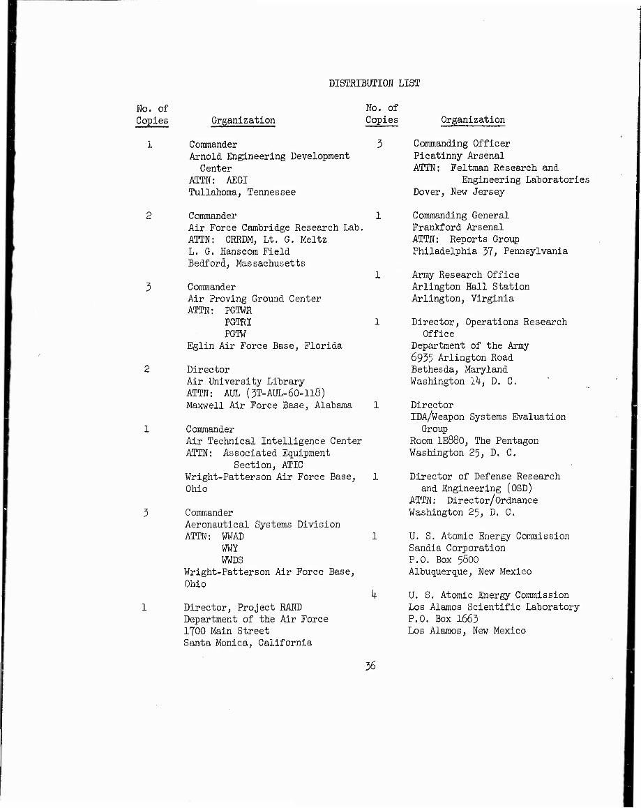
DISTRIBUTION LIST
No. of No. of Copies Organization Copies
1 Commander Arnold Engineering Development
Center ATTN: AEOI Tullahoma, Tennessee
3
Commander Air Force Cambridge Research Lab. ATTN: CRRDM, Lt. G. Meltz L. G. Hanscom Field Bedford, Massachusetts
Commander Air Proving Ground Center ATTN: PGTWR
PGTRI PGTW
Eglin Air Force Base, Florida
Director Air University Library ATTN: AUL (5T-AUL-60-118) Maxwell Air Force Base, Alabama
Commander Air Technical Intelligence Center ATTN: Associated Equipment
Section, ATIC Wright-Patterson Air Force Base, Ohio
Commander Aeronautical Systems Division
ATTN: WWAD WWY WWDS
Wright-Patterson Air Force Base,
Ohio
Director, Project RAND Department of the Air Force 1700 Main Street Santa Monica, California
Organization
Commanding Officer
Picatinny Arsenal
ATTN: Feltman Research and Engineering Laboratories
Dover, New Jersey
Commanding General
Frankford Arsenal ATTN: Reports Group Philadelphia 37> Pennsylvania
Army Research Office Arlington Hall Station Arlington, Virginia
Director, Operations Research Office
Department of the Army
6955 Arlington Road Bethesda, Maryland Washington 1^, D. C.
Director IDA/Weapon Systems Evaluation
Group Room 1E880, The Pentagon Washington 25, D. C.
Director of Defense Research and Engineering (OSD)
ATTN: Director/Ordnance Washington 25, D. C.
U. S. Atomic Energy Commission Sandia Corporation P.O. Box 58OO Albuquerque, New Mexico
U. S, Atomic Energy Commission Los Alamos Scientific Laboratory
P.O. Box 1665 Los Alamos, New Mexico
36

DISTRIBUTION LIST
No. of Copies Organization
U, S. Atomic Energy Commission University of California Lawrence Radiation Laboratory ATTN: Dr. Sidney Fernbach
Dr. John Foster Mr. Bruce Crowley
Technical Information Division
P.O. Box 808 Livermore, California
Director National Aeronautics and
Space Administration 1520 H Street Washington 25, D. C.
Aerojet-General Corporation 6352 North Irwindale Road Azusa, California
Armour Research Foundation ATTN; F. Porzel Illinois Institute of Technology Center
Chicago l6, Illinois
Boeing Airplane Company ATTN: Mr. W. A. Pearce Wichita, Kansas
No. of Copies
Boeing Airplane Company ATTN: Mr. J. Christian ■
Unit Seattle Ik, Washington
CONVAIR A Division of General
Dynamics Corporation
P.O. Box 1950 San Diego 12, California
CONVAIR A Division of General
Dynamics Corporation Fort Worth 1, Texas
Armament
Organization
Chance-Vought Aircraft Company
ATTN: Dr. C, C. Wan
P.O. Box 5907 Dallas, Texas
Cornell Aeronautical Lab., Inc ATTN: Elma Evans, Librarian
kkff Genessee Street Buffalo 5, New York
Douglas Aircraft Company
Long Beach, California
General Electric Research Lab, P.O. Box 1088 Schenectady, New York
Grumann Aircraft Engineering Corp.
ATTN: Armament Group Bethpage, Long Island, New York
Hughes Aircraft Company ATTN: Mr. Dana Johnson,
Research and Development Laboratories
Florence Avenue at Teale Street Culver City, California
Lockheed Aircraft Corporation ATTN: Mr. R. A. Bailey
Division Engineer Military Operations Research
Division Burbank, California
The Martin Company ATTN; Mr. S. L. Rosing
Mall No. 356 Middle River, Maryland
Baltimore 3j Maryland
Midwest Research Institute
ATTN; B. L. Rhodes 425 Volker Boulevard Kansas City 10, Missouri
57

DISTRIBUTION LIST
No. of No. of Copies Organization Copies
1 McDonnell Aircraft Corporation ATTN: Armament Group P.O. Box 516 St. Louis 5, Missouri
2
North American Aviation, Inc.
ATTN: Mr. D. H. Mason Mr. J. Ward 1 Engineering Technical File
12.21k Lakewood Boulevard Downey, California
Radioplane 1 A Division of Northrop Aircraft,
Incorporated P.O. Box 511 1 Van Nuys, California
The Rand Corporation ATTN: H. L. Brode
F. R. Gilmore 1 25OO Colorado Avenue Santa Monica, California
Republic Aviation Corporation Farmingdale, Long Island, 1 New York
Applied Physics Laboratory The Johns Hopkins University 8621 Georgia Avenue 1 Silver Spring, Maryland
California Institute of Technology ATTN: H. W. Leipmann 5 Guggenheim Aeronautical Laboratory Pasadena, California
The Johns Hopkins University 1 Institute for Cooperative Research 5506 Greenway Baltimore 10, Maryland
58
Organization
Massachusetts Institute of Technology
ATTN: Dr. J. R. Ruetenik Dr. Emmett A. Witraer, Room il-l-219
Cambridge 39; Massachusetts
Purdue University Director of Statistical Lab.
ATTN: Dr. Kossach Lafayette, Indiana
Stanford Research Institute Menlo Park, California
University of Michigan Department of Physics
ATTN: Dr. 0. Laporte Ann Arbor, Michigan
University of Utah Institute of Rate Processes
ATTN: M. A. Cook Salt Lake City, Utah
Professor W. Bleakney Princeton University Palmer Physical Laboratory Princeton, New Jersey
Dr. S. R. Brinkley Alcoa Building Pittsburgh 19, Pennsylvania
Mr. Benjamin Day 16^ Cornell Quarters Ithaca, New York
Professor K. 0. Friedrichs New York University Applied Mathematics Panel New York, New York
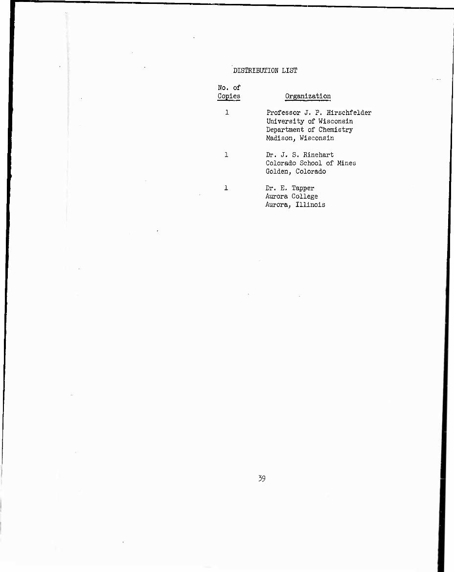
DISTRIBUTION LIST
No. of Copies Organization
Professor J. P. Hirschfelder University of Wisconsin Department of Chemistry Madison^ Wisconsin
Dr. J. S. Rinehart Colorado School of Mines Golden, Colorado
Dr. E. Tapper Aurora College Aurora, Illinois
59

a O frl
H xi a
p a) a ra a a)
<£ p 3 (-1 w to
5 a
«
Ä
i
•4 h Q 0
rA a) o «
SB
:J UN at ui ■
(1) o
'Ü ID
ID ■H (-> Ul ^
p ui «i w d r] w ») o d 41 ai oi 0)
H o ti 0 P 3, W p, -p Pi 01 w o1
h X ill H -H •rl 01 01 'd = 0) 'd d
±> <U ä QJ 111 UD ^J UU t) Cl B S3 q oi a a q 3 [H 'H U 'rl r-H ^ (| ill d ui ai a) ,o a d o h P, • P, m w a)
ill ui ^ üi J3
ai K
ui 111
0) J1 (■i iiü h -p -p 3 -H O h O C 3 01 01 Oj Ü)
s oi o H a 41 ß 3 01 0)
w är-\ d oi in ■p D* al d -H a) a oi 3 h P( oi
i d +> Pi-H -- 0) O rH
P, tl] Tj
OH W 01 d H M Ql P
■H d oi a H X! -H PH 'H 4) ~>. H H • !>. «1 P
O r-, O H tu Oj UN rH H 3
■^ w & a IM tn o 3 a s • O UN O 01 -H rA
■p (1) 0 n m
4J
III p
§ !3 Ll\
■rl 1 01 tn ^l
■a 0' a B 1 t,H
O in in
XI p > tl ^ . 111
01 in p u
p Ui ■n in rt ui Si O ti 01 01 H n M i p
rn
01
+• P. in 1-1
■d "ill
H 01 3 d
0) 01
s s a 01
o P
P( P. 111 (/] 01 ui in in XI
p 111 01 li p Ul li)
HI h 111 (1 (1
1 1 Pi 1 ■$
tlH
■d >>
o ((1 SI in
■a Ü rri
> ■d s fl ■d (U > >
a «i
HJ •rl tH 1/1 o ^J h n n p, rt O 0)
H in In d in
0)
p >i ill 111 P n ä n
H U
m P OI H Pi u s p +J ill H
■a l-i in
N U l-i p d H ii II t) a p
III ill in s .0 ^ 0) U —f H rH O fd Cl I-j id i^ r4 :d 3 H fl 0) U)
4J D* W 01 d <LI :^ J-i rt
IT. P O a) ;s .u (u -r-t
ää
I« > ■p d p M 01 o d P p( -3 -H oi o H P "-J o
p . m oi d t
■H p oi d -ri Pi
01
4= Hl P
, in T! „ 1A
ui 'tf~j-
QD 3' X) a H
■H 01 "^ >, tn iJ
tl^
I.! '8 p H XI 11 bi P 01 l-l 01 | OJ a m
H in 10 CJ OJ ill
i3B§
as
01 rt
111
o H O
rl i£l 0\
o s
o H O
O o I •I o
o rä
■r) 01 "d tl) oi ;> d o) o
■H 3 > H <H tn o § o o PtV d
H i oi h d, p >, 0) oi X xl Q o P 0) HÖH
•H P, O a) a 'H
0) p
d 'd 0)
P.?, fl u o o)
■d
0 Si a P 0) XI
01 P
P u d p oi oi 0) ri o H § I* 3 0) 8 T5 o p w « 3
a H o fl oi w
to 3 H ri p o' tri td d 0) 3 P 0) fl P ■o p Ü 0) > ,a oi -n P p p P P P, -rl d 0) ■
Ml ii in ,d P d u) -P p -rl 0) oi d
J P P S
o) P
o d p P !>, 3 (H p( -ri -H P, tn fl 0) O r-t 1A P -n o (u 03 tf*^
P XI SrH in tu d E-i to 3 X)
•H d oi a H XI -H P4 -r-i O)^-, E-i H • ^ w P
O ^ O H (tn 0! 1A rH rH 3
- O 01 +3
3 1A 0) 0) • IM m H as oi M P ip
Pi O
•H a) 3
-d -d 3
3 m 0) xi oi 'd
•H P tn p ü • ■i.> in oi in d d (fl «i o d 41 oi o) 0)
rH Q p a p 3 (i) fi, p p, 01 M O1
P X 0) H H -H tu oi 'd = oi TJ d P 0) XJ
i oi M^ u)fl o xl d oi d 0) oi EH -H O -H ri P
p, .,
4) oi d h 0 d P P !>. 3 tin •P -H Pi in fl „
oi O H tA P -o o oi cd 'd\
in oi d iH M 3 Xi •H d oi Ö H xl -p p, yl 11 ~> EH H • >. « P
O !•> O H tp ol 1A rH H 3
*-^ g Si & W H-i O 3 o i/\ o (A